1
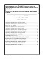
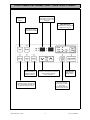
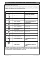
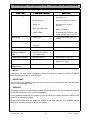
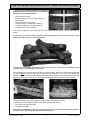
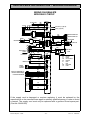
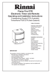
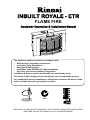
INBUILT ROYALE - ETR FLAME FIRE Customer Operation & Installation Manual This appliance shall be installed in accordance with: • Manufacturers Installation Instructions • Local Gas Fitting Regulations • Municipal Building Codes • Installation code AS/NZS 5601 ‘Gas Installations’ • Any other local relevant Statutory Regulation Installation & Service must be performed by an authorised person. This heater is NOT designed to be built directly into a combustible opening. For combustible opening installations, a Rinnai zero clearance kit must be used and is available from your gas appliance retailer. All Rinnai gas products are A.G.A. certified ISO 9001 Lic 4983 SAI Global INSTALLER: PLEASE LEAVE THIS MANUAL WITH THE END USER AFTER INSTALLATION END USER: RETAIN THIS MANUAL FOR FUTURE REFERENCE WARNING IMPROPER INSTALLATION, ADJUSTMENT, ALTERATION, SERVICE OR MAINTAINENANCE CAN CAUSE PROPERTY DAMAGE, PERSONAL INJURY OR LOSS OF LIFE. INSTALLATION AND SERVICE MUST BE PERFORMED BY AN AUTHORISED PERSON. This manual applies to the IB35 ETR only: Inbuilt Royale ETR - NG/LPG Table of Contents CUSTOMER INFORMATION - CONTROL PANEL .................................................. 1 CUSTOMER INFORMATION - SETTING THE CLOCK ........................................... 4 OPERATING THE TIMERS ...................................................................................... 5 CUSTOMER INFORMATION - SAFETY POINTS .................................................... 6 CUSTOMER INFORMATION - ERROR CODES...................................................... 9 CUSTOMER INFORMATION - TROUBLE SHOOTING ......................................... 10 CUSTOMER INFORMATION - IMPORTANT POINTS........................................... 12 CUSTOMER INFORMATION - SPECIFICATIONS ................................................ 13 INSTALLERS INFORMATION - LOCATION .......................................................... 14 TECHNICAL SPECIFICATION ............................................................................... 15 INSTALLATION INTO MASONRY FIREPLACE & CHIMNEY ................................ 17 INSTALLATION IN TO A COMBUSTIBLE OPENING ............................................ 20 INSTALLERS INFORMATION - LOG INSTALLATION........................................... 24 INSTALLERS INFORMATION - WIRING DIAGRAM.............................................. 26 INSTALLATION / COMMISSIONING CHECKLIST ................................................ 27 CUSTOMER INFORMATION - CONTACTS........................................................... 29 Inbuilt Royale - ETR - ii - Issue 4 ©Rinnai CUSTOMER INFORMATION - CONTROL PANEL TIME/TEMP Display Shows either the time of day, temperatures or coded error messages. LOCK Button Indicates lock function CLOCK ADJUSTMENT AND TIMER INDICATORS Indicates that clock or dual timer programme is being set. Flame Function Med /High heat setting and overides thermostat TIMER Indicator Indicates that TIMER 1 or TIMER 2 has been selected to operate. TIME / TEMP Adjustment Increases or decreases the temperature setting as well as changing hours or minutes. AUTO OFF When ON, Thermostat turns heat down to OFF. OVERRIDE Temporarily changes operation from ON to OFF or OFF to ON, until next programmed setting is reached. Inbuilt Royale - ETR ON/OFF Button Main Switch for turning ON/OFF. (Pilot only) When OFF, Thermostat turns heat down to LOW. -1- Issue 4 ©Rinnai Issue 4 CUSTOMER INFORMATION - OPERATION IMPORTANT: You must read understand these instructions before operating the heater. and fully the controls. To operate the lock simply press the LOCK button. The function is activated immediately and the LOCK indicator will glow. • To Open the Control Panel Lift lightly in the centre of the lid. The control panel lid will then open backward to an angle. To Deactivate the LOCK simply press the LOCK button for 3 seconds and the LOCK indicator will go out. The LOCK can be deactivated at any time in this way. • To turn the unit ‘ON’ Press the ON/OFF button to operate the heater. The ON indicator will glow green. The spark generator will be heard before the burner ignites and the ON indicator glows red, indicating that the heater is alight. When the heater warms up, the fan will automatically start. Note: Initially at turning ‘ON’ only the front and middle burner, low, will ignite. After 8 minutes middle burner, high and rear burner, high will ignite. This will occur each time the appliance is switched on. If the heater does not ignite on initial use, this may be due to air remaining in the gas supply line. The spark generator will only continue for 15 seconds. After this it will be necessary to press the ON/OFF button OFF, then ON again. If the appliance fails to ignite after 4 attempts, contact Rinnai as a service call may be required. • To turn the unit ‘OFF’ Simply press the ON/OFF button to switch off the heater. The ON indicator light will go out. The Fan will continue to operate for several minutes after the burner has gone out in order to cool the appliance. Do not unplug the appliance while the fan is running. • Room Temperature Adjustment The room temperature and pre-set temperatures can only be displayed and adjusted when the heater is running. Press the “” button to increase the temperature setting or “” button to decrease the temperature setting. The temperatures can be preset to: a) [L] low (about 10°C) b) [16°C] to [26°C] in 1°C steps c) [H] (continuously high) When the 'Set' temperature is lower than the current room temperature at time of ignition, only the front burner will ignite on the low setting. If the 'Auto Off' function has been selected, the heater will revert to pilots only operation after a short time period. When ever the pilots are lit the ON indicator will glow red. • Lock The lock function will help to prevent accidental operation as well as small children from altering Royale - Inbuilt - ETR During normal operation the LOCK may be activated and all controls, other than the OFF switch, will be locked. Deactivating the LOCK releases the controls. If the LOCK is activated whilst the heater is turned OFF, then all functions will be locked. If the heater is turned OFF while the LOCK is activated, it cannot be turned ON again until the LOCK is deactivated. • Flame To operate the Flame function, simply press the FLAME button. This function will automatically override the thermostat and set the heater to a default Medium / High heat setting for full visual flame effect. • Auto Off To operate the AUTO OFF function, simply press the AUTO OFF button. When the AUTO OFF function is selected, the indicator light will illuminate and the thermostat will turn the burners down to the OFF heat setting when the selected temperature is reached. When the AUTO OFF function is not selected, the indicator light will go OFF and the thermostat will turn the burners down to the LOW heat setting when the selected temperature is reached. • Override This function is intended to be used to manually override the current operation of the heater. For example; if the heater is in standby mode (i.e. between finishing time and starting time of a Timer) and the OVERRIDE button is selected, then the heater will begin to operate and heat the room. To operate the OVERRIDE simply press the OVERRIDE button. The OVERRIDE indictor will flash. To manually deactivate the OVERRIDE simply press the OVERRIDE button again. The OVERRIDE indicator will go out, and the heater will return to standby mode. The heater will continue to operate on OVERRIDE until the OVERRIDE button is pressed again, or one of the Timers takes over the operation of the appliance. This means that the OVERRIDE mode will automatically drop out if a programmed starting time is reached. The appliance will then return to operating at times programmed into the Timer(s). -2- Issue 4 - ©Rinnai CUSTOMER INFORMATION - OPERATION Remote Control The Remote Control will not turn the heater ON if Timer(s) have been selected. To manually operate when Timer(s) are not selected, simply press the ON or OFF button. To alter the temperature at anytime while the heater is operating, simply press the or button. TO REPLACE BATTERY Simply open the back of the remote control and replace Lithium battery. TYPE: CR 2032 ON BUTTON Operates the heater manually. OFF BUTTON Stops heater manually. TEMPERATURE ADJUSTMENT Increases or decreases the temperature setting. BATTERY Power source for operating remote control Some fluorescent lights may interfere with the transmission of remote control signals, in this case changing the position from which you are operating the remote control may help. Avoid getting the remote control wet, or dropping it. The remote control works within 5 metres and at an angle of 40° to the receiver which is located on the lower front edge of the heater. Only use the battery type specified (CR2032). Remove the battery if control is not going to be used for a long period. This will help avoid damage from leaking batteries. If the Timer(s) have been selected, and the heater is in standby mode, and the OFF button on the Remote Control is pressed, the Timer(s) will be deactivated. Royale - Inbuilt - ETR -3- Issue 4 - ©Rinnai CUSTOMER INFORMATION - SETTING THE CLOCK Setting the Clock When the appliance is first plugged in or after a power failure, the digital display with show --:-- As an example, let’s set the clock to 10:35 am; Press the SET TIMES button once, the Clock indicator will flash. Press and hold the “” button; the minutes will begin to change first then the time will change by whole hours. Release the button when AM 10:00 shows on the Digital Display. Confirm that you have selected AM, a small indictor on the left hand side of the Digital Display indicates the AM setting. Press and hold the “” button again, release the button when AM 10:35 shows. If you go past AM 10:35, then the “” button can be used to change the time settings in reverse. Press the Timer Set button five times to lock in and complete setting the time. The Clock and Timer indicators will go out. A small indicator on the Digital Display will flash to show that the Clock is operating. Programming the ON / OFF Timers Before programming the Timers you must ensure that the clock has been set to the correct time. As an example, let’s program Timer 1 to heat the room by 7:10 am and finish at 9:00 am. Press the Set Times button twice. The Digital Display will show AM 6:00. Timer 1 indicator will flash. Press the “” button until AM 7:00 appears, release the button, then press it again until AM 7:10 appears. (Press the “” button if you go past AM 9:00). Press the Set Times button three times to lock in the program time. The Digital Display will show the current time. A small indicator on the Digital Display will flash to shown that the display has returned to the clock. Timer 2 is programmed in the same way, remember to ensure that the Timer 2 indicator is flashing when you program in the desired setting. The Timers can be programmed to operate for any two periods in any 24 hours. Turn to the next page to operate the dual timer. The programmed time must be selected and locked-in within one minute of the On Timer indicators flashing otherwise the programmed times will not be retained in the system memory. Inbuilt Royale - ETR -4- Issue 4 - ©Rinnai Issue 4 OPERATING THE TIMERS Operating the Timers Before operating the Timer(s), the clock time must be correct and a starting time and finishing time for the Timer(s) must be programmed. See page 5. The two Timers operate in the same way. This heater does not commence operation at the programmed starting time. It will attempt to heat a room by the programmed starting time. See Pre-heat, for further explanation. To select the Timer(s) to commence heating. Check the time shown on the Digital Display is correct. Check the ON and OFF times, for both Timers if necessary. Press the ON/OFF button to operate the heater. The ON indicator will glow green and the heater will being to operate. Select the desired temperature setting. Press the Timer 1 and/or Timer 2 button(s). The timer indicator(s) will glow and the heater will remain on standby until one hour prior to the time programmed into the selected Timer(s) is reached. When this time is reached, the Timer indicator will flash and the heater will operate. The ON indicator glows red when the heater commences operation. Actual start time will depend on temperature selected and current room temperature. (see pre-heat for further details). Set and Forget Operation Your heater can be operated to alternate between Timers automatically during cold weather by selecting Timer 1 and Timer 2 together. Both Timer indicators will glow. The appliance will remain on standby at intervals between the programmed finishing and starting times of each Timer. While the heater is operating during programmed intervals the Timer indicator will flash. If there is a power failure, the system memory will retain the Timer programs, and the clock will stop at the time the power goes off. The clock will start again when the power comes back on, but the time will be slow by the duration of the power failure. To set the clock to the correct time after the power has come back on, simply follow the instructions on page 4. Preheat This function operates automatically in conjunction with either of the timers. When a timer is selected, the heater may operate anywhere within an hour prior to the programmed starting time of the timer. The preheat function will attempt to preheat the room by the programmed ON time This function is called pre-heat due to the way it operates. The room temperature is sensed one hour before reaching the programmed time of either timer. The temperature differential at the time of sensing the room governs how long before the program ON time the microcomputer will operate the heater and ignite the burner. Inbuilt Royale - ETR -5- Issue 4 - ©Rinnai CUSTOMER INFORMATION - SAFETY POINTS Clearances must be maintained. min. 300mm min. 300mm min. 300mm min. 1000mm Note that side and vertical clearances are measured from the edge of the glass. Do not restrict the warm air discharge by placing articles in front of the heater. Do not spray aerosols whilst the heater is operating. Most aerosols contain butane gas, which can be a fire hazard if used near the heater when it is in use. This appliance must not be used for any purpose other than heating. Inbuilt Royale - ETR -6- Issue 4 - ©Rinnai CUSTOMER INFORMATION - SAFETY POINTS Issue 4 Do not allow anyone to post articles through the louvres. Do not allow young children or the infirm to sleep directly in front of the heater. Young children should be supervised at all times. Hand or body contact with the louvres must be avoided. Do not allow curtains or other flammable or combustible materials to come into contact with the heater. Do not place containers of liquid on top of the heater. Liquid spillage can cause extensive damage to the appliance. Inbuilt Royale - ETR -7- Issue 4 - ©Rinnai CUSTOMER INFORMATION - SAFETY POINTS Do not allow anyone to sit on or lean against the appliance. Do not unplug the heater while it is in operation or while the fans are still cycling. Do not turn the heater off by unplugging it from the wall. Do not remove the Dress Guard. The dress guard is fitted to this appliance to reduce the risk of fire or injury from burns and no part of it should be permanently removed. For protection of children or the infirm, a secondary guard is recommended. DO NOT CONNECT TO AN LPG GAS CYLINDER INDOORS. DO NOT PLACE ARTICLES ON OR AGAINST THIS APPLIANCE. DO NOT USE OR STORE FLAMMABLE MATERIALS NEAR THIS APPLIANCE. DO NOT SPRAY AEROSOLS IN THE VICINITY OF THIS APPLIANCE WHILE IT IS IN OPERATION. Inbuilt Royale - ETR -8- Issue 4 - ©Rinnai CUSTOMER INFORMATION - ERROR CODES ERROR CODE MESSAGE E The Flame Fire ETR has the ability to check its own operation continuously. If a fault occurs, an Error Message will flash on the Digital Display of the control panel. This assists with diagnosing the fault, and may enable you to overcome a problem without a service call. Please quote the code displayed when enquiring about service. Error Code --:-- Probable Cause Comments • Ignition Failure • Check gas is turned on. • Service call if repeated • Flame Failure • Check gas is turned on. • Service call if repeated • Overheat • Service call • Room Overheat • Lower room temperature to less than 40°C. • Room temperature • Sensor Faulty • Service call • Room temperature • Service call • Overheat temperature • Sensor faulty • Service call • Faulty ON / OFF switch • Service call • • Faulty Solenoids • Service call • Faulty Flame Rod • Service call • Communication error • Turn heater OFF, then ON again • Flue Block • Service call • Power Failure • Turn heater OFF, then ON again In all cases, you may be able to clear the Error Message simply by turning the heater OFF, then ON again. If the Error Message still remains or returns on the next operation, please contact your nearest service contact and arrange for a service call. Inbuilt Royale - ETR -9- Issue 4 - ©Rinnai CUSTOMER INFORMATION - TROUBLE SHOOTING SYMPTOM Burner will not light POSSIBLE CAUSES SOLUTION • No power present • Ensure power cord is plugged in and turned on. • No gas present • Ensure gas supply is turned on. • Power cut • Re-ignite when power is restored. • Air in gas supply pipe • Purge air (installer). • Ignition failure • Repeat lighting procedure (refer operating instructions page 2). Smell of gas • Leaking gas • Turn off gas at meter and call installer. Fan not working • No power supply to fan • Call Rinnai Service Dept. / Agent. • Faulty fan Small soot deposit • Normal operation • No action required. Severe soot deposits forming on Glass or Logs • • • Inadequate flue system Incorrect gas pressure Log misalignment • Call Rinnai Service Dept. / Agent. Condensation on glass • Normal operation • Allow heater to warm up. Streaky lines on glass • Normal operation • For cleaning call Rinnai Service Department / Agent. Digital Error Message on Control Panel • Electronic fault detected • See Error Message page 9. • NOTE: If you have any other faults or problems, please refer to your installer or a Rinnai Customer Care Centre Consultant on 1300 555 545. • IMPORTANT: Do not remove any panels or attempt to carry out any service work other than that mentioned in the Trouble Shooting chart. • SERVICE: Rinnai has a service and spare parts network with personnel who are fully trained and equipped to give the best service on your Rinnai appliance. If your appliance needs service, please ring one of the service contact numbers located on the back of this instruction booklet. Rinnai recommends that this appliance should be serviced annually by a qualified service technician, including inspection of the flue system. Inbuilt Royale - ETR - 10 - Issue 4 - ©Rinnai Issue 4 Intentionally Blank Inbuilt Royale - ETR - 11 - Issue 4 - ©Rinnai CUSTOMER INFORMATION - IMPORTANT POINTS Issue 4 Unpack the heater and check for damage. DO NOT INSTALL DAMAGED HEATER. If the heater is damaged, contact your supplier for advice. Before installing the heater, check the label for the correct gas type (see rating plate, front right hand side of bottom panel). Refer to local gas authority for confirmation of the gas type if you are in doubt. Included in the carton Customer operation information, roll of sealing foam, ceramic log set and granules. Before installing this product, please read this manual carefully. IMPORTANT POINTS The user shall be advised that appliances incorporating a live fuel effect, and designed to operate with luminous flames, may exhibit slight carbon deposits. 1. The appliance must be installed in accordance 12. If the supply cord, gas hose or glass are with the local gas and electrical authority damaged or require replacing, they must be replaced by the manufacturer or the manufacturers regulations. agent or similarly qualified person in order to avoid 2. For information on gas consumption, see data a hazard. plate on the appliance. 13. Do not allow articles to be posted through the 3. Ensure that the area in which the appliance is louvres or openings. installed has adequate fixed ventilation, this fixed ventilation must be provided as per AS/NZS 5601 14. Do not spray aerosols near this heater whilst it Clause 5.4 to 5.4.5. is in use. Most aerosols contain butane gas which 4. DO NOT connect to an LPG Gas cylinder can be a fire hazard if used near this heater when in use. Use of aerosols, paint, polishes etc whilst indoors. this heater is in use may cause unpleasant smells. 5. This appliance must not be installed where curtains or other combustible materials could 15. Do not operate/install this heater in places come into contact with it. In some cases curtains where painting is taking place, or in places such as hair dressing salons, where there may be a lot of may need restraining. fluff and dust, and where aerosols are used. 6. This appliance is not designed to be built directly 16. Do not unplug the heater while it is still in into a combustible opening. operation or the fan is operating. 7. Heater must not be located below a power 17. Do not turn off heater by unplugging it at the socket-outlet. wall. 8. The local gas and electrical authorities will be 18. Do not place articles on or against this able to advise on local regulations. appliance. 9. Heat emanating from the front of this appliance may over time affect the appearance of some 19. Do not place clothes racks etc. directly in front materials used for flooring such as carpet, vinyl, of the heater. cork or timber. This effect may be amplified if the air in the room contains cooking vapours or cigarette smoke. To avoid this possibility, it is recommended that a mat be placed in front of this appliance, extending at least 750 mm in front of it. 20. Do not store flammable materials near the heater. Combustible materials must not be allowed where the heater could ignite them. 21. The heater may emit smoke when first started which may take up to 2 Hours to disappear. This is 10. The appliance is not intended for use by young part of the burning in process and normal, ensure children or infirm persons without supervision. adequate ventilation during this period. 11. Young children should be supervised to ensure 22. The guard is fitted to this appliance to reduce they do not play with the appliance. the risk of fire or injury from burns and no part of it should be permanently removed, for protection of young children or the infirm, this secondary guard is required. Issue 4Inbuilt Royale - ETR - 12 - Issue 4 - 26/10/11 CUSTOMER INFORMATION - SPECIFICATIONS Model: IB35ETRN (NG) IB35ETRL (Propane) Description: Rinnai Inbuilt Radiant/Convector, glass fronted, ceramic log space heater with forced convection & natural draft flue system. Output: 33 MJ/hr Natural Gas and Propane. Gas Control: Rinnai Electronic Control Valve Burners: Ceramic Logs, Ember bed and Heat burner Gas Inlet: 15 mm. Copper Flare Connection. Test Point Pressure: Natural Gas 0.95 kPa; Propane: 2.00 kPa. Flue: Natural Draught Flue Termination: In fireplace not applicable. When fitted with Flue Kit (Zero Clearance Box). Fig. 5.3 of AS/NZS 5601. Ignition: Electronic spark Power Supply: 240 V 50 Hz unit is supplied with 3 pin plug and supply lead, replace only with Rinnai P/N. 90179599 (Aust). 6765B (NZ). Fan: Tangential 2 speed, Watt Rating 90W. Rating Plate location: Bottom panel, front right hand side Weight: 54 Kgs. Inbuilt Royale - ETR - 13 - Issue 4 - 26/10/11 Issue 4 INSTALLERS INFORMATION - LOCATION The following pages contain information relating to Installation and Service. Installation and Service must be carried out by an authorised person only. 8. Before installing the heater, inspect the chimney, flue piping and/or solid fuel burning fire place and remove any combustible materials. When positioning the heater, the main points governing the location are: 9. A zero clearance kit is available from your gas appliance retailer for installations into a combustible opening. 1. Flue connection and terminal to comply with AS/NZS 5601. Only Rinnai flue components can be used. 2. Warm air distribution. • Mantles A mantle is permitted providing the clearances below are met. 3. Ensuring that the area in which the appliance is installed has adequate fixed ventilation, this fixed ventilation must be provided as per AS/ NZS 5601. 150 maximum 300 mm Minimum 4. The heater must not be installed where curtains or other combustible materials could come into contact with it. In some cases, curtains may need restraining. See diagram below for minimum clearances required. min. 300mm min. 300mm min. 300mm min. 1000mm Note that side and vertical clearances are measured from the edge of the glass. 5. The heater is not designed to be built into bookcases or shelves. For combustible opening installations a Rinnai zero clearance kit must be used and is available from your gas appliance retailer. 6. This heater must be mounted on a hearth not less than 50mm thick and at least the width and depth of the heater. The hearth surface must be flat and level to support the entire heater or zero clearance box. If the heater or zero clearance box base are not properly supported noise and vibration may result. 7. A gas appliance must not be connected to a chimney flue serving a separate solid-fuel burning appliance. Inbuilt - Royale ETR 10. Check that room ventiliation complies with local regulations. 11. This heater has a power cord with a three pin plug supplied. The power cord passes through the slot in the lower left or right hand side of the heater front assembly. Rinnai recommend the heater be plugged into a 240V, 10A earthed power point. The power point must be a minimum of 300 mm to the side of the heater (it must not be above the heater). Alternatively - unit can be direct wired if the power supply is to be concealed. Consult a qualified electrician if direct wiring is required as it must comply to AS/NZS 5601 and AS3000. - 14 - Issue 4- ©Rinnai TECHNICAL SPECIFICATION Model: Description: Gas input rate: Gas Control: Burners Test Point Pressure: Gas Connection: Flue terminal: Fan: Combustion system Logs: Ignition system: Operation: Safety Devices: Combustion method: Installation type: Weight: Flue requirement: Inbuilt Royale - ETR Flame Fire IB35ETR Rinnai ETR Inbuilt Radiant/Convector, glass fronted, ceramic log space heater with forced convection and natural draught flue system Natural Gas Propane Pilot and ‘Low’: Medium: High: Rinnai electronic control Ember bed and flame burner 8 MJ/hr 8 MJ/hr 25 MJ/hr 25 MJ/hr 33 MJ/hr 33 MJ/hr 0.95 kPa 2.00 kPa 1/2” compression flare The flue must terminate to atmosphere vertically above the roof in line to comply to AS/NZS 5601. Rinnai Appliance warranty conditions will be voided if non Rinnai Flue components are fitted. Rinnai are NOT CERTIFIED for use with non Rinnai Flueing components. Tangential 2 speed, power rating 47 Watts Multi port burner Ceramic Continuous spark electronic ignition Push button to light pilot and burners Touch pad control. Thermostatically controlled to light pilot and burners. Able to select the following features: - Timer - Auto Off function - Flame function - Child lock Naturally aspirated burner Inbuilt only 54 Kgs. A Rinnai approved flue system is mandatory for this appliance, to be installed in accordance with AS/NZS 5601. The manufacturer reserves the right to change or modify specifications without notice. Inbuilt Royale - ETR - 15 - Issue 4- ©Rinnai INSTALLERS INFORMATION - DIMENSIONS 17 319 400 585 167 150 17 400 Inbuilt Royale - ETR - 16 - 583 575 695 ~ 700 8 910 Issue 4- ©Rinnai INSTALLATION INTO MASONRY FIREPLACE & CHIMNEY A Rinnai Flexible Flue Liner Kit (Flexliner01) is mandatory in all masonry fireplace and chimney installations. MASONRY FIREPLACE HEATER 1. Check Dimensions of Fireplace Check dimensions of fireplace and if necessary bring them to the dimensions shown. • If the fireplace opening is larger than the heater, a 100mm wide decorative surround Part no. for the External top panel FLFRSEXT (Black only) and these panels are available from your local gas appliance retailer. 2. Check conditions of fireplace/chimney 600 mm Minimum Width 800 mm Maximum Width 695 mm Minimum Height 700 mm Maximum Height • 405 mm Minimum Depth Hearth 50 mm Minimum Height The chimney must be physically checked first and must meet the following set criteria along with local regulations. Failure to meet these criteria will not only void the product warranty but may affect the performance of the product. a): All loose/broken bricks must be replaced or repaired ensuring the chimney is of sound construction and does not leak. b): Any under floor air supply to the fireplace must be completely sealed off to prevent secondary air draw. c): Total flue length MUST NOT be less than 3 metres and flue cowl must terminate above the chimney in accordance with AS/NZS 5601. d): The chimney must be swept clean and be free of soot and creosote that may have built up if previously used for a solid fuel fire. e): The hearth surface must be flat and level to support the entire heater. If the heater is not properly supported noise and vibration may result. 3. Install Flue For installations into a masonry fireplace a Rinnai Flexible Flue system is required. (Flexliner01). Rinnai rigid flame fire flueing is not suitable. Assemble flue in accordance with the instructions supplied with the flue kit. At this point do not connect the flue spigot to the heater. Royale - Inbuilt ETR - 17 - Issue 4 ©Rinnai INSTALLATION INTO MASONRY FIREPLACE & CHIMNEY 4. Apply sealing strips to back of heater • Peel protective backing off the foam strips supplied with the Heater. • Attach strips to rear of casing as shown. The strip is intended to form a seal between the heater and the fireplace. • If an adequate seal cannot be formed with this strip an other means of sealing must be used. (eg.non combustible insulation), between the fireplace and the heater body. SEALING STRIPS 5. Run Gas Supply • For pipe sizing refer to your local gas installation codes. • Copper supply should be run leaving a 1/2” flared connection at the position shown. • Attach the stainless steel flexitube supplied to the flare connection. 6. Install decorative surround to the face of the fireplace (Part No. SFFRB) If required. Preparation for Heater installation 1. Open both side panels. 2. Remove two screws on both sides of the top glass retainer, lift retainer and remove from heater. 3. Loosen screws on bottom glass retainer. 4. Carefully lift glass out of bottom channel. 5. Carefully remove log packaging (Refer to page 24 for log installation). 6. Remove the front and middle burners by undoing the left hand end screws. Slide the burners to the left, and lift out (Caution: Do not misplace the aeration sleeve from the burner venturi). 7. Slide out and remove the bottom louvre rods, which are held in place by tension. 8. Remove the screws from both ends of the lower front panel (Caution: 240V switch attached to panel). 9. Remove the top and bottom screws from the centre louvre rod-retaining bracket. Royale - Inbuilt ETR - 18 - Issue 4 ©Rinnai INSTALLATION INTO MASONRY FIREPLACE & CHIMNEY 10.Slide out the fan partition tray exposing the gas control and flare connection. 11. Slide the heater carefully into position, while feeding the stainless steel flexi-tube through the gas supply access opening at right hand rear. 12.Bend the flexi-tube and connect to the gas control valve. Note: All foreign materials such as filings and swarf must be purged from the gas supply before connection as they may damage the gas controls. 13. Attach flue pipe to heater flue spigot in accordance with Flexible Flueing instructions. 14.Seal and secure the heater to the fireplace. There are pre-drilled holes in the heater surround behind the doors. Drill additional holes if the existing ones are not in suitable positions. NOTE: on completion of work a gas leak test must be carried out. Use a soapy solution on all gas connections. Leaks will be visible when the soapy solution forms bubbles. When finished wipe soapy solution with a rag to remove residue. 7. Log Installation - for Log installation details, please refer to page 24. Replace and refit all parts that have been removed in reverse order. 8. Commissioning - for Commissioning details, please refer to page 27. Royale - Inbuilt ETR - 19 - Issue 4 ©Rinnai INSTALLATION IN TO A COMBUSTIBLE OPENING Rinnai understands that not all households have an existing masonry fireplace. Rinnai offers the option of installing the Flame Fire Royale into a decorative fireplace for either a single storey or two storey home. All you need is a flat wall which can be either external or internal and a zero clearance box. A Rinnai Rigid flue MUST also be installed (Part No. FLFKIT05 / FLFTWKIT). Flexible flue kits are not suitable. The Zero clearance box can be installed hard against the combustible timber framework of the mock fireplace due to the air gap created beneath the appliance with the use of the plinth panel, and the air gap between the outer panel of the Flame fire and the Rinnai Zero clearance box. (Part No. ZEROR). Only this Zero Clearance Box must be used for these installations. Rinnai Flame Fire Rigid Flueing allows the air to be drawn in through the louvres in the plinth panel, pass around the sides and back of the Flame fire heater and be drawn away through the outer skin of the flue. The resulting air flow will keep the Zero clearance box panels at a safe operating temperature. Refer to Rinnai Flueing Installation Manual for Rinnai Flame Fire Heaters. Available flueing options as follows: OBSTRUCTION A HEATER Royale - Inbuilt ETR ZERO CLEARANCE BOX ZERO CLEARANCE BOX B HEATER - 20 - ZERO CLEARANCE BOX C HEATER Issue 4 ©Rinnai INSTALLATION IN TO A COMBUSTIBLE OPENING Steps for Installation: 1. Determine the preferred location of the heater. • Check roof space for any flue obstructions. 2. Construct frame in accordance with the dimensions shown: 745 mm 440 mm 810 mm 3. Install Rinnai Zero Clearance Box (ZEROR) • ‘Zero clearance’ means the panels of metal from the zero clearance box can be in contact with any combustible material. • The hearth surface must be flat and level to support the zero clearance box. If the zero clearance box base is not properly supported noise and vibration may result. Kit contains: - Zero Box - Supporting Plinth - Complete decorative Surround - Installation Instructions Royale - Inbuilt ETR - 21 - Issue 4 ©Rinnai INSTALLATION IN TO A COMBUSTIBLE OPENING 4. Run gas supply. For pipe sizing refer to your local gas installation codes. Copper supply should be run leaving a flared connection at the position shown. Attach the stainless steel flexitube supplied to the flared connection. 5. Install Rinnai Flame Fire Rigid Flueing as per the instructions supplied with the flue kit, taking careful note of the following: Flue termination above the roof must comply with AS/NZS 5601. Vertical flue length must be no less than 3.0 metres. The inner and outer flues must be supported independently of the heater to comply with AS/NZS 5601 6. Apply plaster and paint. 7. Assemble the plinth and base supports. Slide the plinth and base supports and heater into the zero clearance box, making sure the plinth is located correctly between the heater and the zero clearance box. 8. Slide the slip socket onto the inner flue spigot of the heater and tighten to seal. Refer flueing instructions for details. 9. Attach gas supply. Note: All foreign materials such as filings must be purged from the gas supply, before connection as they may damage the gas controls. Note: on completion of work a gas leak test must be carried out. Use a soapy solution on all gas connections. Leaks will be visible when the soapy solution forms bubbles. When finished wipe soapy solution with a rag to remove residue. Royale - Inbuilt ETR - 22 - Issue 4 ©Rinnai INSTALLATION IN TO A COMBUSTIBLE OPENING 10.Install top decorative surround to face of fireplace. 11. Log Installation - for log installation details, please refer to page 24. 12.Commissioning - for Commissioning details, please refer to page 27. Royale - Inbuilt ETR - 23 - Issue 4 ©Rinnai INSTALLERS INFORMATION - LOG INSTALLATION 1. The log set is packed inside the heater and the packaging must be removed prior to installing the log set in its correct position • • • • • • Open both side panels. Remove fastenings on both sides of the top glass retainer. Lift retainer away from heater. Loosen screws on bottom glass retainer. Carefully lift glass out of bottom channel. Carefully remove log packaging. The log set is supplied in one piece with two holes underneath for location onto the pins inside the heater. 2. Place the log set into the heater ensuring that the locating pins enter the two locating holes on the bottom face of the logset, if not already attached. 3. Gently place loose ember bed material in front of the Front Log. Do not pour as dust particles from the plastic bag as it may block the burner ports. Level it with a pencil or screw driver and remove excess material. Note: The ember bed material must be placed after the logs are fitted. If the logs are to be removed for any reason, the ember bed material must be removed first and replaced after the logs are refitted. Any material that prevents the logs sitting flat on the burner top can upset the burning pattern and performance of the heater. 4. • • • • Replace glass and top glass retainer, tighten bottom glass retainer screws. Note: Fit glass so that the join/gap in the glass seal is at the bottom. Take care not to damage seals. Reinstall side panels. Note: When first lighting the heater, the logs need to be burnt in, which may take approximately 2 hours. The flame colour may change after the initial burning in period. Inbuilt Royale - ETR - 24 - Issue 4 - ©Rinnai INSTALLERS INFORMATION - TESTING & COMMISSIONING 1. To check burner pressure • Turn OFF and disconnect the 240V power supply connection. • Turn ON Gas supply. • Refer to Data Plate or the Technical Specification section in this manual for burner pressures. • If you are unable to get the unit to operate correctly, refer to Trouble Shooting on page 10 before contacting your local service contacts listed on the back page of this booklet. • It may take approximately 2 hours of operation for the logs to achieve their full flame pattern and glow. • Open right hand side front cover panel (Remove 1-screw located under the front of the panel). It is the responsibility of the installer to check that under normal operating conditions of the appliance, all flue gases are exhausted to the outside atmosphere and that there is no spillage of combustion gases into the room. Refer to AS/NZS 5601. • Remove 240V electrical cover. 2. Commissioning • Remove test point screw and attach manometer to test point, the test point is on the lower right hand side of the valve assembly. Installation and Commissioning Checklist • Connect the 240V power supply. Caution with the electrical panel open 240V terminals will be exposed. • Light heater, turn to High heat setting, wait 8 minutes and check pressure. • If adjustments are necessary, the regulator is situated on the lower right hand corner and should be set to the pressures on the data-plate. • Disconnect the 240V power supply. • Remove manometer and replace test point screw, check for gas escapes at test point screw. • Replace electrical cover and secure side panel. • Reconnect the power supply. • Turn the heater on and off a few times to check ignition. • All burner aerations are factory preset and cannot be adjusted. Inbuilt Royale - ETR Complete the Installation Checklist and the Installer details on page 27 and make sure that this instruction book is left with the customer. Instruct Customer Make sure the customer understands the instructions and the operation of the appliance. Advise that : • The guard on this appliance conforms to A.G.A. requirements. It is designed to prevent the risk of injury from burns and no part of it should be permanently removed. IT DOES NOT GIVE FULL PROTECTION TO YOUNG CHILDREN OR THE INFIRM. • For protection of young children or the infirm, a secondary guard is recommended. • This appliance is designed to operate with luminous flames and may exhibit slight carbon deposits. • During the initial burning in period, (approx. 2 hours) some smoke and smell may be experienced during this period, the heater should be run on the High position in a well ventilated room. - 25 - Issue 4 - ©Rinnai INSTALLERS INFORMATION - WIRING DIAGRAM WIRING DIAGRAM ETR WITH DELAY CIRCUIT AC 220V/240V XLP-02V(JST) 1 CN1 2 XLP-03V(JST) 1 2 CN3 3 (BR) (BL) YLP-03V(JST) YLR-03V 1 2 3 1 2 3 * TRANSFORMER SPARKER (GY) (GY) 4 5 6 6 5 4 3 2 1 (REAR) SV2 (BW) (RW) (R) (W) (BK) (BK) (BL) (BL) (R) CONTROL RECEIVER LO HI XLP-04V 2 4 1 3 C XMP-03V 3 2 CN8 1 917687-1 3 2 CN11 1 (BK) 917690-1 (R) 917694-1 1 FLUE BLOCK THERMISTER (W) OVER HEAT THERMISTER (BK) ROOM TEMP THERMISTER 10KR-8M (FRONT) (BK) (REAR) (BR) FLAME RODS (BW) 4 2 3 1 (BW) 8 min DELAY TIMER CN2 (BL) REMOTE (BK) (R) (NT)4820X6 THERMAL FUSE SV4 MIDDLE BURNER LOW SV6 REAR BURNER 12 11 10 9 8 7 (W) (BW) (R) FAN MOTOR SV5 MIDDLE BURNER HIGH (BL) (BW) (Y) CN5 (BW) SV3 FRONT BURNER 240V (1,3) (BR/BL) XLP-12V(JST) (NT)4820-4001X2 or(AMP)176948-1X1 ELECTRODES SV1 220V/230V (1,2) (BK/W) 179862 CN4 1 2 3 (FRONT) * BK = BLACK W = WHITE BW = BLACK/WHITE BR = BROWN BL = BLUE R = RED RW = RED/WHITE GY = GREY 6 5 4 CN6 3 2 1 CN10 (BL) UNIT DISPLAY CONTROL 10P (R) 10 1 CN9 8P (BL) 08KR-8M 8 917692-1 If the supply cord is damaged or requires replacing, it must be replaced by the manufacturer or the manufacturers agent or similarly qualified person in order to avoid a hazard. The supply cord must only be replaced with a genuine Rinnai spare part. (Part No. 90182065) Inbuilt Royale - ETR - 26 - Issue 4- ©Rinnai INSTALLATION / COMMISSIONING CHECKLIST (To be completed by certified Gas Installer) NO YES Model: _______________________________ 1. Was a fireplace inspection carried out? (i.e. clearances, combustibles etc). 2. Was a Rinnai flue system installed in accordance with the instructions? 3. Have specified gas pressures been checked and set? 4. Are decorative logs located correctly? 5. Have ember granules been placed and free of dust and powder? 6. Has the appliance been test fired for correct operation? (All Burners light without delay) 7. Is the end-user fully aware of operating procedure? 8. Is the hearth surface flat and level to support the entire heater or zero clearance box? INSTALLERS / GAS FITTER DETAILS Company name: ____________________________________________________ Installers name: ____________________________________________________ Address: ____________________________________________________ ____________________________________________________ ____________________________________________________ Phone: __________________ Mobile: __________________________ Certificate of Compliance / Certification Number:__________________________ (* where applicable) Authorised Persons – Licence Number: _______________________________ Signed:________________________ Inbuilt Royale - ETR Date:___________________ - 27 - Issue 4- ©Rinnai NOTES Inbuilt Royale - ETR - 28 - Issue 4- ©Rinnai CUSTOMER INFORMATION - CONTACTS The Rinnai Flame Fire Heater Family Inbuilt Royale IB35 / IB35ETR Australia Pty. Ltd. Head Office Freestanding Royale FS35 / FS35ETR Inbuilt Slimfire IB25 ABN 74 005 138 769 Internet: www.rinnai.com.au E-mail: [email protected] 10-11 Walker Street, Braeside, Victoria 3195 P.O. Box 460 Tel: (03) 9271 6625 Fax: (03) 9271 6622 National Help Line Spare Parts & Technical Info Tel: 1300 555 545* Fax: 1300 555 655* *Cost of a local call Higher from mobile or public phones. Head Office, New Zealand Internet: www.rinnai.co.nz E-mail: [email protected] 691 Mt. Albert Road, Royal Oak, Auckland P.O. Box 24-068 Tel: (09) 625 4285 Fax: (09) 624 3018 Inbuilt Royale - ETR 24 Hour Service Tel: 0800 746624 (0800 Rinnai) - 29 - E&TG03-016 Issue 4 - 26/10/11 (7083-D)