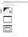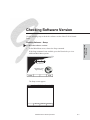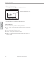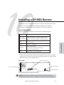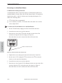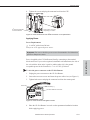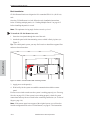
1
CP-20A Documentation
q
CP-20A Control Panel Operation
q
CP-20A Control Panel Quick Reference Guide
Contents
Chapter 1 – Introducing the CP-20A
CP-20A Control Panel . . . . . . . . . . . . . . . . . . . . . . . . . . . . . . . . . . . . . . . . . . . . . . . . . . . . 1-2
Graphic LCD . . . . . . . . . . . . . . . . . . . . . . . . . . . . . . . . . . . . . . . . . . . . . . . . . . . . . . . . . 1-2
Dynamic Menu Area. . . . . . . . . . . . . . . . . . . . . . . . . . . . . . . . . . . . . . . . . . . . . . . . . . 1-2
Dynamic Menu Keys. . . . . . . . . . . . . . . . . . . . . . . . . . . . . . . . . . . . . . . . . . . . . . . . . . 1-3
Function Key. . . . . . . . . . . . . . . . . . . . . . . . . . . . . . . . . . . . . . . . . . . . . . . . . . . . . . . . . 1-3
Take Key . . . . . . . . . . . . . . . . . . . . . . . . . . . . . . . . . . . . . . . . . . . . . . . . . . . . . . . . . . . . 1-3
Technical Support . . . . . . . . . . . . . . . . . . . . . . . . . . . . . . . . . . . . . . . . . . . . . . . . . . . . . . . . 1-4
Chapter 2 – Executing Switches
Executing Switches – Selecting Input First . . . . . . . . . . . . . . . . . . . . . . . . . . . . . . . . . . 2-2
Executing Switches – Selecting Output First. . . . . . . . . . . . . . . . . . . . . . . . . . . . . . . . . 2-4
Changing the Virtual Matrix . . . . . . . . . . . . . . . . . . . . . . . . . . . . . . . . . . . . . . . . . . . . . . . 2-7
Chapter 3 – Disconnecting Switches
Disconnecting an Input . . . . . . . . . . . . . . . . . . . . . . . . . . . . . . . . . . . . . . . . . . . . . . . . . . . 3-2
Disconnecting an Output . . . . . . . . . . . . . . . . . . . . . . . . . . . . . . . . . . . . . . . . . . . . . . . . . . 3-4
Chapter 4 – Verifying Signal Status
Verifying Input Status . . . . . . . . . . . . . . . . . . . . . . . . . . . . . . . . . . . . . . . . . . . . . . . . . . . . . 4-1
Verifying Output Status . . . . . . . . . . . . . . . . . . . . . . . . . . . . . . . . . . . . . . . . . . . . . . . . . . . 4-3
Chapter 5 – Executing Presets
Local Presets . . . . . . . . . . . . . . . . . . . . . . . . . . . . . . . . . . . . . . . . . . . . . . . . . . . . . . . . 5-1
Global Presets . . . . . . . . . . . . . . . . . . . . . . . . . . . . . . . . . . . . . . . . . . . . . . . . . . . . . . . 5-1
Defining Global Presets . . . . . . . . . . . . . . . . . . . . . . . . . . . . . . . . . . . . . . . . . . . . . . . . . . . 5-2
Executing Global Presets. . . . . . . . . . . . . . . . . . . . . . . . . . . . . . . . . . . . . . . . . . . . . . . . . . 5-4
Chapter 6 – Adjusting Audio
Adjusting Volume. . . . . . . . . . . . . . . . . . . . . . . . . . . . . . . . . . . . . . . . . . . . . . . . . . . . . . . . . 6-2
Adjusting Digital Input Gain . . . . . . . . . . . . . . . . . . . . . . . . . . . . . . . . . . . . . . . . . . . . . . . . 6-4
CP-20A Control Panel Operation
Contents
Chapter 7 – Adjusting LCD Contrast
Adjusting Contrast – Main Menu . . . . . . . . . . . . . . . . . . . . . . . . . . . . . . . . . . . . . . . . . . 7-1
Adjusting Contrast – Setup . . . . . . . . . . . . . . . . . . . . . . . . . . . . . . . . . . . . . . . . . . . . . . . 7-2
Chapter 8 – Reloading Configuration File
Chapter 9 – Checking Software Version
Checking Software – Setup . . . . . . . . . . . . . . . . . . . . . . . . . . . . . . . . . . . . . . . . . . . . . . . 9-1
Setup Version Screen . . . . . . . . . . . . . . . . . . . . . . . . . . . . . . . . . . . . . . . . . . . . . . . . 9-2
Chapter 10 – Installing a CP-20A Remote
General Specifications. . . . . . . . . . . . . . . . . . . . . . . . . . . . . . . . . . . . . . . . . . . . . . . . . . . 10-1
Rear View . . . . . . . . . . . . . . . . . . . . . . . . . . . . . . . . . . . . . . . . . . . . . . . . . . . . . . . . . . . . . 10-1
Connecting to an AutoPatch Router . . . . . . . . . . . . . . . . . . . . . . . . . . . . . . . . . . . . . . 10-2
Communication Cable Specifications. . . . . . . . . . . . . . . . . . . . . . . . . . . . . . . . . . 10-2
Applying Power . . . . . . . . . . . . . . . . . . . . . . . . . . . . . . . . . . . . . . . . . . . . . . . . . . . . . . . . . 10-3
Power Requirements. . . . . . . . . . . . . . . . . . . . . . . . . . . . . . . . . . . . . . . . . . . . . . . . 10-3
Rack Installation . . . . . . . . . . . . . . . . . . . . . . . . . . . . . . . . . . . . . . . . . . . . . . . . . . . . . . . . 10-4
Linking Multiple Panels . . . . . . . . . . . . . . . . . . . . . . . . . . . . . . . . . . . . . . . . . . . . . . . . . . 10-5
Power Requirements. . . . . . . . . . . . . . . . . . . . . . . . . . . . . . . . . . . . . . . . . . . . . . . . 10-5
Appendix A – System Error Codes
Most Common System Error Codes. . . . . . . . . . . . . . . . . . . . . . . . . . . . . . . . . . . . . . . . A-1
Troubleshooting. . . . . . . . . . . . . . . . . . . . . . . . . . . . . . . . . . . . . . . . . . . . . . . . . . . . . . . . . . A-2
Technical Support . . . . . . . . . . . . . . . . . . . . . . . . . . . . . . . . . . . . . . . . . . . . . . . . . . . . . . . . A-2
Index
CP-20A Control Panel Operation
Introduction
Introducing the CP-20A
This section is specifically written for AutoPatch enclosures with either a front or
remote CP-20A Control Panel. The CP-20A is used for controlling the system’s
switches and system attributes. Although control panels are optional, we
recommend one per system for system verification, redundant control, and
troubleshooting.
Figure 1 illustrates an Optima Distribution Matrix with a CP-20A Control Panel.
Other models may vary slightly in appearance.
Figure 1: Front view of an Optima with a CP-20A Control Panel
Note: AutoPatch enclosures can also be controlled using BCS (Basic Control
Structure) commands transmitted through an external controller; see the BCS
Serial Control Protocol or Serial Control Operation section of this binder.
AutoPatch control software can also be used to control an AutoPatch system;
see the AutoPatch Software & Documentation CD for more information.
CP-20A Control Panel Operation
1-1
Introducing the CP-20A
Introduction
CP-20A Control Panel
A CP-20A Control Panel has a graphic LCD with a dynamic menu area,
dynamic menu keys, a Function key, and a Take key.
Power Indicator (or LED System Indicators)
Graphic LCD
Dynamic Menu Area
Take Key
Function Key
Figure 2: Close-up view of a CP-20A Control Panel
Dynamic Menu Keys
Graphic LCD
An LCD with a backlight displays instructions and selection entry fields. The
backlight automatically turns off after 15 minutes of inactivity. Press any key
to reactivate the light.
Note: To adjust the contrast of the LCD, see Chapter 7, “Adjusting LCD
Contrast.”
Dynamic Menu Area
The menu displays different command options across the bottom of the LCD,
depending on which screen is active. These options can be accessed using the
corresponding dynamic menu keys. The menu options are multilevel with the
ability to display custom input (source) and output (destination) names (labels).
The default channel name (e.g., O_Ch:0003 for Output 3) appears unless the
name has been modified in the configuration file* using X NConnect (see
Chapter 8 of the Installation & Setup section of this binder).
* The configuration file (.xcl file) contains routing and control information for
a system and is modified with XNConnect, which graphically displays the file.
Both the configuration file and XNConnect are on the AutoPatch Software &
Documentation CD.
1-2
CP-20A Control Panel Operation
CP-20A Control Panel
Dynamic Menu Keys
section of the dynamic menu area. The four keys across the bottom allow you to
select from the corresponding commands across the lower part of the screen.
The four keys on the right side of the LCD are used to scroll through lists, adjust
sliders, select an action, or return to the previous screen. The associated
commands on the right side of the Dynamic Menu Area vary by screen and
include the following:
q
Back key – Use to return to the last screen. This key will not undo a
completed operation.
q
Arrow keys – Use to scroll through lists and adjust sliders. When scrolling,
press and hold an arrow key to increase scrolling speed. When at the bottom
of a list, press the down key to access the top of the list. When at the top of a
list, press the up key to access the bottom of the list. Scrolling from the
bottom of a list may sometimes be more efficient depending on the matrix
size.
q
Select key – Use to enter a selection. This key will not execute operations.
Function Key
The Function key accesses the Main Menu screen. From the Main Menu, the
Function key accesses additional menu options. From any other screen, it returns
to the Main Menu.
Take Key
The Take key functions much like the Enter key on a computer keyboard.
Pressing the Take key instructs the system to execute a selected operation. Prior
to pressing the Take key, the individual operation component(s) must be selected
by pressing the Select key.
CP-20A operations combine the following four basic tasks:
To choose a command, press the dynamic menu key along the bottom that
corresponds with the command you want to choose.
To locate values for fields (such as virtual matrix, input, output, and preset
values), press the dynamic menu keys on the right that correspond to the arrows.
To enter a selection, press the Select key. (The key that corresponds to the
Select option on the dynamic menu area is found on the right.)
To execute an operation, press the Take key.
CP-20A Control Panel Operation
1-3
Introduction
The keys select commands and settings. Each menu key lines up with a different
Introducing the CP-20A
Introduction
Technical Support
For questions concerning CP-20A operations, note the specific information
(including error or warning messages) and contact AutoAssist.
AutoPatch provides technical support 24 hours a day, 7 days a week (except for
U.S. holidays). Before contacting technical support with a question, please
consult the product documentation. If this binder cannot fully answer your
question, have your serial number ready and contact your authorized AutoPatch
Dealer or AutoPatch AutoAssist. (The serial number is normally located on the
rear of the enclosure or remote panel; see also the Installation & Setup section of
this binder.)
AutoAssist Contact Information
ä Toll-free U.S. and Canada – 800-622-0246
ä International – 509-235-2636
ä Website – www.autopatch.com
ä Email – [email protected]
1-4
CP-20A Control Panel Operation
A switch is an active connection between an input (source) device and one or
more output (destination) devices. The signals routed in a switching operation are
individual signals or groups of individual signals coming through the connectors
on the rear of an enclosure. Executing a preset is a quick way to execute multiple
switches at a time. For information on presets, see page 5-1.
Switches are executed on the default virtual matrix unless otherwise specified.
When specifying a virtual matrix, be sure it includes all the signals you want to
route. The number of the virtual matrix (VM) that operations are currently being
performed on is displayed in the upper-right of the display. If you need to change
the virtual matrix, see “Changing the Virtual Matrix” on page 2-7.
You can return to the Main Menu screen at any time by pressing the Function
key.
Note: In each switch command, you can enter multiple output signals, but only
one input signal. However, you must select the input first in order to select
multiple outputs. The Take key must be pressed for the switch operation to
execute.
CP-20A Control Panel Operation
2-1
Executing Switches
Executing Switches
Executing Switches
Executing Switches – Selecting Input First
The example below routes Input 33: Satellite Dish to
Output 6: Reception Monitor on Virtual Matrix 0.
To execute a switch:
1. At the Main Menu screen, choose the Change command.
Executing Switches
If the Change command is not available, press the Function key to view
additional Main Menu options.
High Performance
Signal Routing
CHANGE
STATUS
DISC
AUDIO
The Change Input screen appears, displaying the available input options.
CHANGE INPUT:__
1
2
3
4
5
6
7
8
9
10
11
:
:
:
:
:
:
:
:
:
:
:
Reception Mic
Reception Cam
Reception DVD
Mic #1 Control
Mic #2 Control
Mic #3 Control
VCR #1 Control
VCR #2 Control
VCR #3 Control
DVD #1 Control
DVD #2 Control
V M
Input
VM:0
Back
Rm
Rm
Rm
Rm
Rm
Rm
Rm
Rm
Select
Output
2. Locate Input 33: Satellite Dish by scrolling through the list using
the arrow keys. (Press and hold an arrow key to scroll quickly.)
CHANGE INPUT:__
23
24
25
26
27
28
29
30
31
32
33
:
:
:
:
:
:
:
:
:
:
:
Podium Cam Mtg Rm A
Audience Cam Mtg Rm A
Tape Deck Mtg Rm A
Main Mic Mtg Rm A
Audience Mic Mtg Rm A
Podium Cam Mtg Rm B
Audience Cam Mtg Rm B
Tape Deck Mtg Rm B
Main Mic Mtg Rm B
Audience Mic Mtg Rm B
Satellite Dish
V M
2-2
VM:0
Input
Back
Select
Output
CP-20A Control Panel Operation
Selecting Input First
3. Press the Select key.
The Change Output screen appears, displaying the available output options.
CHANGE OUTPUT:__
:
:
:
:
:
:
:
:
:
:
:
Main Control Monitor
Codec Control Rm
Monitor 1 Control Rm
Monitor 2 Control Rm
Monitor 3 Control Rm
Reception Monitor
Reception Speakers
Lobby Monitor
Main Monitor Rm A
Audience Monitor Rm A
Podium Monitor Rm A
VM:0
Back
Executing Switches
1
2
3
4
5
6
7
8
9
10
11
Input:33
Select
Note: If other outputs are already routed to the selected input, they are
highlighted on the Change Output screen.
4. Locate Output 6: Reception Monitor by scrolling through the list using
the arrow keys.
CHANGE OUTPUT:__
1
2
3
4
5
6
7
8
9
10
11
:
:
:
:
:
:
:
:
:
:
:
Input:33
Main Control Monitor
Codec Control Rm
Monitor 1 Control Rm
Monitor 2 Control Rm
Monitor 3 Control Rm
Reception Monitor
Reception Speakers
Lobby Monitor
Main Monitor Rm A
Audience Monitor Rm A
Podium Monitor Rm A
VM:0
Back
Select
5. Press the Select key.
Output 6: Reception Monitor is highlighted.
CHANGE OUTPUT:__
1
2
3
4
5
6
7
8
9
10
11
:
:
:
:
:
:
:
:
:
:
:
Input:33
Main Control Monitor
Codec Control Rm
Monitor 1 Control Rm
Monitor 2 Control Rm
Monitor 3 Control Rm
Reception Monitor
Reception Speakers
Lobby Monitor
Main Monitor Rm A
Audience Monitor Rm A
Podium Monitor Rm A
VM:0
Back
Select
CP-20A Control Panel Operation
2-3
Executing Switches
Note: You can select multiple outputs by scrolling through the list and pressing
the Select key. The Select key functions as a toggle switch, selecting and
unselecting outputs in the list each time it is pressed. Any outputs that are already
routed to the selected input are highlighted. Unselecting an output(s) results in its
disconnection when the Take key is pressed.
Executing Switches
6. Press the Take key to execute the operation.
The switch from Input 33: Satellite Dish to Output
6: Reception Monitor occurs as soon as the Take key is pressed.
The system returns to the Change Input screen.
7. Make additional switches.
Or press the Function key to return to the Main Menu screen.
Executing Switches – Selecting Output First
You can execute a switch by selecting one output first; however, to select
multiple outputs you must use the “Selecting Input First” method (see page 2-2).
The example below routes a signal to Output 15: Main Monitor Rm B from
Input 10: DVD #1 Control Rm on Virtual Matrix 0.
To execute a switch:
1. At the Main Menu screen, choose the Change command.
If the Change command is not available, press the Function key to view
additional Main Menu options.
High Performance
Signal Routing
CHANGE
2-4
STATUS
DISC
AUDIO
CP-20A Control Panel Operation
Selecting Output First
The Change Input screen appears.
CHANGE INPUT:__
:
:
:
:
:
:
:
:
:
:
:
Reception Mic
Reception Cam
Reception DVD
Mic #1 Control
Mic #2 Control
Mic #3 Control
VCR #1 Control
VCR #2 Control
VCR #3 Control
DVD #1 Control
DVD #2 Control
V M
Input
Back
Rm
Rm
Rm
Rm
Rm
Rm
Rm
Rm
Select
Output
2. Choose the Output command from the bottom of the screen.
The Change Output screen appears, displaying the available output options.
CHANGE OUTPUT:__
1
2
3
4
5
6
7
8
9
10
11
:
:
:
:
:
:
:
:
:
:
:
VM:0
Main Control Monitor
Codec Control Rm
Monitor 1 Control Rm
Monitor 2 Control Rm
Monitor 3 Control Rm
Reception Monitor
Reception Speakers
Lobby Monitor
Main Monitor Rm A
Audience Monitor Rm A
Podium Monitor Rm A
V M
Input
Back
Select
Output
3. Locate Output 15: Main Monitor Rm B by scrolling through the list using
the arrow keys. (Press and hold an arrow key to scroll quickly.)
CHANGE OUTPUT:__
12
13
14
15
16
17
18
19
20
21
22
:
:
:
:
:
:
:
:
:
:
:
VM:0
Main Projector Rm A
Speaker Set 1 Rm A
Speaker Set 2 Rm A
Main Monitor Rm B
Audience Monitor Rm B
Podium Monitor Rm B
Main Projector Rm B
Speaker Set 1 Rm B
Speaker Set 2 Rm B
Main Monitor Exec Rm
Aux Monitor Exec Rm
V M
Input
Back
Select
Output
CP-20A Control Panel Operation
2-5
Executing Switches
1
2
3
4
5
6
7
8
9
10
11
VM:0
Executing Switches
4. Press the Select key.
The Change Input screen appears, displaying the available input options.
Executing Switches
CHANGE INPUT:__
1
2
3
4
5
6
7
8
9
10
11
:
:
:
:
:
:
:
:
:
:
:
Output:15
Reception Mic
Reception Cam
Reception DVD
Mic #1 Control
Mic #2 Control
Mic #3 Control
VCR #1 Control
VCR #2 Control
VCR #3 Control
DVD #1 Control
DVD #2 Control
VM:0
Back
Rm
Rm
Rm
Rm
Rm
Rm
Rm
Rm
Select
Note: If an input is already routed to the selected output, it is highlighted on
the Change Input screen.
5. Locate Input 10: DVD #1 Control Rm by scrolling through the list using
the arrow keys.
CHANGE INPUT:__
1
2
3
4
5
6
7
8
9
10
11
:
:
:
:
:
:
:
:
:
:
:
Output:15
Reception Mic
Reception Cam
Reception DVD
Mic #1 Control
Mic #2 Control
Mic #3 Control
VCR #1 Control
VCR #2 Control
VCR #3 Control
DVD #1 Control
DVD #2 Control
VM:0
Back
Rm
Rm
Rm
Rm
Rm
Rm
Rm
Rm
Select
6. Press the Select key.
Input 10: DVD #1 Control Rm is highlighted.
CHANGE INPUT:__
1
2
3
4
5
6
7
8
9
10
11
2-6
:
:
:
:
:
:
:
:
:
:
:
Output:15
Reception Mic
Reception Cam
Reception DVD
Mic #1 Control
Mic #2 Control
Mic #3 Control
VCR #1 Control
VCR #2 Control
VCR #3 Control
DVD #1 Control
DVD #2 Control
VM:0
Back
Rm
Rm
Rm
Rm
Rm
Rm
Rm
Rm
Select
CP-20A Control Panel Operation
Changing the Virtual Matrix
7. Press the Take key to execute the operation.
The switch to Output 15: Main Monitor Rm B from Input
10: DVD #1 Control Rm occurs as soon as the Take key is pressed.
The system returns to the Change Output screen.
8. Make additional switches.
Or press the Function key to return to the Main Menu screen.
Virtual matrices are defined in XNConnect and stored in the system’s
configuration file (see the XNConnect Help file). Systems usually have a virtual
matrix that contains all signals, so that any input can be routed to any or all
outputs. The same system may have other VMs that switch only audio signals or
only video signals.
Occasionally you may need to execute switches (or other operations) on a virtual
matrix other than the current virtual matrix. Changing the virtual matrix does not
change the default virtual matrix. The system will revert to switching on the
default virtual matrix when the power is cycled.
The example below gives the steps for changing from routing signals on the
“Audio follow Video,” virtual matrix, to routing on the “Audio, Stereo” virtual
matrix that switches only audio signals. Although this example accesses the VM
(Virtual Matrix) option from the Change menu, this option can be selected from
most of the command menus found along the bottom of the screen.
To change the virtual matrix:
1. At the Main Menu screen, choose the Change command.
If the Change command is not available, press the Function key to view
additional Main Menu options.
High Performance
Signal Routing
CHANGE
STATUS
DISC
AUDIO
CP-20A Control Panel Operation
2-7
Executing Switches
Changing the Virtual Matrix
Executing Switches
The Change Input screen appears.
Executing Switches
CHANGE INPUT:__
1
2
3
4
5
6
7
8
9
10
11
:
:
:
:
:
:
:
:
:
:
:
Reception Mic
Reception Cam
Reception DVD
Mic #1 Control
Mic #2 Control
Mic #3 Control
VCR #1 Control
VCR #2 Control
VCR #3 Control
DVD #1 Control
DVD #2 Control
V M
Input
VM:0
Back
Rm
Rm
Rm
Rm
Rm
Rm
Rm
Rm
Select
Output
2. Choose the VM command from the bottom of the screen.
The Virtual Matrix screen appears with the current VM highlighted.
VIRTUAL MATRIX:__
VM0
VM1
VM2
: Audio follow Video
: Video
: Audio, Stereo
Back
Select
3. Locate VM2: Audio, Stereo by scrolling through the list using the arrow
keys.
VIRTUAL MATRIX:__
VM0
VM1
VM2
: Audio follow Video
: Video
: Audio, Stereo
Back
Select
4. Press the Select key to enter the selection and return to the previous screen.
The system will execute all operations on VM2: Audio, Stereo until another
VM is selected or the power is cycled.
2-8
CP-20A Control Panel Operation
Disconnecting Switches
Disconnecting a switch deactivates the connection between an input (source)
signal and one or more output (destination) devices. Disconnecting an input
disconnects all outputs receiving that source signal. You can disconnect a switch
by selecting either inputs or outputs from the CP-20A Control Panel.
If you need to change the virtual matrix, see “Changing the Virtual Matrix” on
page 2-7.
Note: You can select multiple inputs or outputs by scrolling through the list and
pressing the Select key. The Select key functions as a toggle switch, selecting
and unselecting inputs or outputs in the list each time it is pressed. The Take key
must be pressed for the disconnect operation to execute.
CP-20A Control Panel Operation
3-1
Disconnecting
Switches
You can return to the Main Menu screen at any time by pressing the Function
key.
Disconnecting Switches
Disconnecting an Input
The example below disconnects Input 27: Audience Mic Mtg Rm A, on Virtual
Matrix 0 from all outputs it is routed to.
To disconnect an input:
Caution: Disconnecting an input disconnects all outputs receiving that source
signal even if a specific output(s) is selected at the same time.
1. At the Main Menu screen, choose the Disc (Disconnect) command.
Disconnecting
Switches
If the Disc command is not available, press the Function key to view
additional Main Menu options.
High Performance
Signal Routing
CHANGE
STATUS
DISC
AUDIO
The Disconnect Input screen appears, displaying the available input options.
DISCONNECT INPUT:__
1
2
3
4
5
6
7
8
9
10
11
:
:
:
:
:
:
:
:
:
:
:
Reception Mic
Reception Cam
Reception DVD
Mic #1 Control
Mic #2 Control
Mic #3 Control
VCR #1 Control
VCR #2 Control
VCR #3 Control
DVD #1 Control
DVD #2 Control
V M
3-2
Input
VM:0
Back
Rm
Rm
Rm
Rm
Rm
Rm
Rm
Rm
Select
Output
CP-20A Control Panel Operation
Disconnecting an Input
2. Locate Input 27: Audience Mic Mtg Rm A by scrolling through the list
using the arrow keys. (Press and hold an arrow key to scroll quickly.)
DISCONNECT INPUT:__
23
24
25
26
27
28
29
30
31
32
33
:
:
:
:
:
:
:
:
:
:
:
VM:0
Podium Cam Mtg Rm A
Audience Cam Mtg Rm A
Tape Deck Mtg Rm A
Main Mic Mtg Rm A
Audience Mic Mtg Rm A
Podium Cam Mtg Rm B
Audience Cam Mtg Rm B
Tape Deck Mtg Rm B
Main Mic Mtg Rm B
Audience Mic Mtg Rm B
Satellite Dish
V M
Input
Back
Select
Output
3. Press the Select key.
DISCONNECT INPUT:__
23
24
25
26
27
28
29
30
31
32
33
:
:
:
:
:
:
:
:
:
:
:
VM:0
Podium Cam Mtg Rm A
Audience Cam Mtg Rm A
Tape Deck Mtg Rm A
Main Mic Mtg Rm A
Audience Mic Mtg Rm A
Podium Cam Mtg Rm B
Audience Cam Mtg Rm B
Tape Deck Mtg Rm B
Main Mic Mtg Rm B
Audience Mic Mtg Rm B
Satellite Dish
V M
Input
Disconnecting
Switches
Input 27: Audience Mic Mtg Rm A is highlighted.
(Additional disconnects can be selected at this time.)
Back
Select
Output
4. Press the Take key.
Input 27: Audience Mic Mtg Rm A and all outputs connected to it are
disconnected as soon as the Take key is pressed.
The system returns to the Disconnect Input screen.
5. Press the Function key to return the Main Menu screen.
CP-20A Control Panel Operation
3-3
Disconnecting Switches
Disconnecting an Output
The example below disconnects Output 22: Aux Monitor Exec Rm on Virtual
Matrix 0 from its input.
To disconnect an output:
1. At the Main Menu screen, choose the Disc (Disconnect) command.
If the Disc command is not available, press the Function key to view
additional Main Menu options.
Disconnecting
Switches
High Performance
Signal Routing
CHANGE
STATUS
DISC
AUDIO
The Disconnect Input screen appears.
DISCONNECT INPUT:__
1
2
3
4
5
6
7
8
9
10
11
:
:
:
:
:
:
:
:
:
:
:
Reception Mic
Reception Cam
Reception DVD
Mic #1 Control
Mic #2 Control
Mic #3 Control
VCR #1 Control
VCR #2 Control
VCR #3 Control
DVD #1 Control
DVD #2 Control
V M
Input
VM:0
Back
Rm
Rm
Rm
Rm
Rm
Rm
Rm
Rm
Select
Output
2. Choose the Output command from the bottom of the screen.
The Disconnect Output screen appears, displaying the available outputs.
DISCONNECT OUTPUT:__
1
2
3
4
5
6
7
8
9
10
11
:
:
:
:
:
:
:
:
:
:
:
Main Control Monitor
Codec Control Rm
Monitor 1 Control Rm
Monitor 2 Control Rm
Monitor 3 Control Rm
Reception Monitor
Reception Speakers
Lobby Monitor
Main Monitor Rm A
Audience Monitor Rm A
Podium Monitor Rm A
V M
3-4
VM:0
Input
Back
Select
Output
CP-20A Control Panel Operation
Disconnecting an Output
3. Locate Output 22: Aux Monitor Exec Rm by scrolling through the list using
the arrow keys. (Press and hold an arrow key to scroll quickly.)
DISCONNECT OUTPUT:__
12
13
14
15
16
17
18
19
20
21
22
:
:
:
:
:
:
:
:
:
:
:
VM:0
Main Projector Rm A
Speaker Set 1 Rm A
Speaker Set 2 Rm A
Main Monitor Rm B
Audience Monitor Rm B
Podium Monitor Rm B
Main Projector Rm B
Speaker Set 1 Rm B
Speaker Set 2 Rm B
Main Monitor Exec Rm
Aux Monitor Exec Rm
V M
Input
Back
Select
Output
4. Press the Select key.
DISCONNECT OUTPUT:__
12
13
14
15
16
17
18
19
20
21
22
:
:
:
:
:
:
:
:
:
:
:
VM:0
Main Projector Rm A
Speaker Set 1 Rm A
Speaker Set 2 Rm A
Main Monitor Rm B
Audience Monitor Rm B
Podium Monitor Rm B
Main Projector Rm B
Speaker Set 1 Rm B
Speaker Set 2 Rm B
Main Monitor Exec Rm
Aux Monitor Exec Rm
V M
Input
Disconnecting
Switches
Output 22: Aux Monitor Exec Rm is highlighted.
(Additional disconnects can be selected at this time.)
Back
Select
Output
5. Press the Take key.
Output 22: Aux Monitor Exec Rm is disconnected from its input as soon as
the Take key is pressed.
The system returns to the Disconnect Output screen.
6. Press the Function key to return the Main Menu screen.
CP-20A Control Panel Operation
3-5
Verifying Signal Status
Signal status can be verified to confirm that a switch has executed properly or to
confirm correct routing to multiple outputs. Input status and output status both
function on the CP-20A Control Panel. An output can only be connected to one
input; therefore, verifying the status of an output will display only the one input
it is currently connected to.
You can return to the Main Menu screen at any time by pressing the Function
key.
If you need to change the virtual matrix, see “Changing the Virtual Matrix” on
page 2-7.
Verifying Input Status
on Virtual Matrix 0.
Note: If you choose to check the status of an input, all the outputs that are
connected to it will be listed.
To verify the signal status of an input:
1. At the Main Menu screen, choose the Status command.
If the Status command is not available, press the Function key to view
additional Main Menu options.
High Performance
Signal Routing
CHANGE
STATUS
DISC
AUDIO
CP-20A Control Panel Operation
4-1
Verifying
Signal Status
The example below verifies the signal status for Input 31: Main Mic Mtg Rm B
Verifying Signal Status
The Status Input screen appears, displaying the available inputs.
STATUS INPUT:__
1
2
3
4
5
6
7
8
9
10
11
:
:
:
:
:
:
:
:
:
:
:
VM:0
Reception Mic
Reception Cam
Reception DVD
Mic #1 Control
Mic #2 Control
Mic #3 Control
VCR #1 Control
VCR #2 Control
VCR #3 Control
DVD #1 Control
DVD #2 Control
V M
Back
Rm
Rm
Rm
Rm
Rm
Rm
Rm
Rm
Select
Output
Input
2. Locate Input 31: Main Mic Mtg Rm B by scrolling through the list using the
arrow keys. (Press and hold an arrow key to scroll quickly.)
STATUS INPUT:__
Verifying
Signal Status
23
24
25
26
27
28
29
30
31
32
33
:
:
:
:
:
:
:
:
:
:
:
VM:0
Podium Cam Mtg Rm A
Audience Cam Mtg Rm A
Tape Deck Mtg Rm A
Main Mic Mtg Rm A
Audience Mic Mtg Rm A
Podium Cam Mtg Rm B
Audience Cam Mtg Rm B
Tape Deck Mtg Rm B
Main Mic Mtg Rm B
Audience Mic Mtg Rm B
Satellite Dish
V M
Back
Select
Output
Input
3. Press the Select key to enter the selection.
The Status Results screen appears listing the outputs,
13: Speaker Set 1 Rm A , 14: Speaker Set 2 Rm A,
19: Speaker Set 1 Rm B, and 20: Speaker Set 2 Rm B, that are connected
to the input being verified.
STATUS RESULTS:
13
14
19
20
:
:
:
:
Speaker
Speaker
Speaker
Speaker
Set
Set
Set
Set
Input:31
1
2
1
2
Rm
Rm
Rm
Rm
A
A
B
B
VM:0
Back
Note: If the screen is full, more outputs than the ones displayed may be active.
Use the arrow keys to scroll to check for additional active outputs.
4-2
CP-20A Control Panel Operation
Verifying Output Status
4. Press the Back key to return to the Status Input screen to verify the status of
additional signals.
Or press the Function key to return to the Main Menu screen.
Verifying Output Status
The example below verifies the signal status for Output 20: Speaker Set 2 Rm B
on Virtual Matrix 0.
Note: Checking the status of an output will not show other outputs connected to
same input.
To verify the signal status of an output:
1. At the Main Menu screen, choose the Status command.
If the Status command is not available, press the Function key to view
additional Main Menu options.
CHANGE
STATUS
DISC
Verifying
Signal Status
High Performance
Signal Routing
AUDIO
The Status Input screen appears.
STATUS INPUT:__
1
2
3
4
5
6
7
8
9
10
11
:
:
:
:
:
:
:
:
:
:
:
Reception Mic
Reception Cam
Reception DVD
Mic #1 Control
Mic #2 Control
Mic #3 Control
VCR #1 Control
VCR #2 Control
VCR #3 Control
DVD #1 Control
DVD #2 Control
V M
Input
VM:0
Back
Rm
Rm
Rm
Rm
Rm
Rm
Rm
Rm
Select
Output
CP-20A Control Panel Operation
4-3
Verifying Signal Status
2. Choose the Output command from the bottom of the screen.
The Status Output screen appears, displaying the available output options.
STATUS OUTPUT:__
1
2
3
4
5
6
7
8
9
10
11
:
:
:
:
:
:
:
:
:
:
:
VM:0
Back
Main Control Monitor
Codec Control Rm
Monitor 1 Control Rm
Monitor 2 Control Rm
Monitor 3 Control Rm
Reception Monitor
Reception Speakers
Lobby Monitor
Main Monitor Rm A
Audience Monitor Rm A
Podium Monitor Rm A
V M
Input
Select
Output
3. Locate Output 20: Speaker Set 2 Rm B by scrolling through the list using
the arrow keys. (Press and hold an arrow key to scroll quickly.)
STATUS OUTPUT:__
Verifying
Signal Status
12
13
14
15
16
17
18
19
20
21
22
:
:
:
:
:
:
:
:
:
:
:
VM:0
Main Projector Rm A
Speaker Set 1 Rm A
Speaker Set 2 Rm A
Main Monitor Rm B
Audience Monitor Rm B
Podium Monitor Rm B
Main Projector Rm B
Speaker Set 1 Rm B
Speaker Set 2 Rm B
Main Monitor Exec Rm
Aux Monitor Exec Rm
V M
Input
Back
Select
Output
4. Press the Select key to enter the selection.
The Status Results screen appears, displaying the Input,
31: Main Mic Mtg Rm B , routed to the output being verified.
STATUS RESULTS:
Output:20
31 : Main Mic Mtg Rm B
VM:0
Back
5. Press the Back key to return to the Status Output screen to verify the status
of additional signals.
Or press the Function key to return to the Main Menu screen.
4-4
CP-20A Control Panel Operation
Executing Presets
Global and local presets are predefined sets of switches that can be easily executed.
Local Presets
At the time of this publication, local presets cannot be executed using the CP-20A
Control Panel. Local presets are defined in XNConnect (see the XNConnect Help
file) and can be executed using BCS commands. More information on local presets
and other operations executed with BCS commands can be found in the BCS Serial
Control Protocol section of this binder.
Global Presets
Global presets allow you to replicate an entire system state. The system state
includes all current signal routings (regardless of the number of virtual matrices
involved) and any digital gain and/or volume settings. A global preset number is
assigned to a system state during runtime using the CP-20A Control Panel (or BCS
commands) and stored by the system. That system state can then be restored at any
time by selecting the assigned global preset number.
Note: We strongly recommend keeping track of the number used and the system’s
routing state for each global preset. If another system state is assigned a previously
used number, the former state will be automatically overwritten.
Global presets cannot be defined (created) in XNConnect.
Caution: If the system is reconfigured, global presets may be lost, depending on
the method used to load the new configuration file (see the X NConnect Help file).
The example on page 5-2 defines the current system state as 3: Global Preset 3 .
The example on page 5-4 executes 3: Global Preset 3 , which restores the
system to the state it was in when the global preset was defined.
CP-20A Control Panel Operation
5-1
Executing Presets
The CP-20A stores up to 64 global presets and displays 64 numbers. Since the
panel can be used to operate different types of matrix switchers, check the product
documentation for any limitations to the number of supported global presets.
Executing Presets
Defining Global Presets
To define a global preset:
1. Route the system to the desired state.
2. At the Main Menu screen, choose the Global command.
If the Global command is not available, press the Function key to view
additional Main Menu options.
High Performance
Signal Routing
GLOBAL
SETUP
The Execute Global Preset screen appears.
EXECUTE GLOBAL PRESET:__
1
2
3
4
5
6
7
8
9
10
11
:
:
:
:
:
:
:
:
:
:
:
Global
Global
Global
Global
Global
Global
Global
Global
Global
Global
Global
Executing Presets
Execute
Preset
Preset
Preset
Preset
Preset
Preset
Preset
Preset
Preset
Preset
Preset
1
2
3
4
5
6
7
8
9
10
11
Back
Select
Define
3. Choose the Define command from the bottom of the screen.
The Define Global Preset screen appears.
A complete list of numbers is displayed, regardless of whether or not a
system state has been assigned to each number.
DEFINE GLOBAL PRESET:__
1
2
3
4
5
6
7
8
9
10
11
:
:
:
:
:
:
:
:
:
:
:
Global
Global
Global
Global
Global
Global
Global
Global
Global
Global
Global
Execute
5-2
Preset
Preset
Preset
Preset
Preset
Preset
Preset
Preset
Preset
Preset
Preset
1
2
3
4
5
6
7
8
9
10
11
Back
Select
Define
CP-20A Control Panel Operation
Defining Global Presets
Note: If another system state is assigned a previously used number, the former
state will be automatically overwritten.
4. Locate 3: Global Preset 3 by scrolling through the list using the arrow
keys. (Press and hold an arrow key to scroll quickly.)
DEFINE GLOBAL PRESET:__
1
2
3
4
5
6
7
8
9
10
11
:
:
:
:
:
:
:
:
:
:
:
Global
Global
Global
Global
Global
Global
Global
Global
Global
Global
Global
Execute
Preset
Preset
Preset
Preset
Preset
Preset
Preset
Preset
Preset
Preset
Preset
1
2
3
4
5
6
7
8
9
10
11
Back
Select
Define
5. Press the Select key.
3: Global Preset 3 is highlighted.
DEFINE GLOBAL PRESET:__
1
2
3
4
5
6
7
8
9
10
11
:
:
:
:
:
:
:
:
:
:
:
Global
Global
Global
Global
Global
Global
Global
Global
Global
Global
Global
Execute
Preset
Preset
Preset
Preset
Preset
Preset
Preset
Preset
Preset
Preset
Preset
1
2
3
4
5
6
7
8
9
10
11
Back
Select
Define
6. Press the Take key.
The current system state can now be recalled at any time by executing
Executing Presets
3: Global Preset 3 .
The system returns to the Define Global Preset screen.
DEFINE GLOBAL PRESET:__
1
2
3
4
5
6
7
8
9
10
11
:
:
:
:
:
:
:
:
:
:
:
Global Preset 1
Global Preset 2
Global Preset 3
Global Preset 4
Global Preset 5
Global Defining
Preset 6
Global Preset 7
Global Preset 3
Global Preset 8
Global Preset 9
Global Preset 10
Global Preset 11
Execute
Define
7. Press the Function key to return to the Main Menu screen.
CP-20A Control Panel Operation
5-3
Executing Presets
Executing Global Presets
To execute a global preset:
1. At the Main Menu screen, choose the Global command.
If the Global command is not available, press the Function key
to view additional Main Menu options.
High Performance
Signal Routing
GLOBAL
SETUP
The Execute Global Preset screen appears displaying a list of global preset
numbers. (The list includes all preset numbers regardless of whether or not a
system state is assigned to the number.)
EXECUTE GLOBAL PRESET:__
1
2
3
4
5
6
7
8
9
10
11
:
:
:
:
:
:
:
:
:
:
:
Global
Global
Global
Global
Global
Global
Global
Global
Global
Global
Global
Executing Presets
Execute
Preset
Preset
Preset
Preset
Preset
Preset
Preset
Preset
Preset
Preset
Preset
1
2
3
4
5
6
7
8
9
10
11
Back
Select
Define
2. Locate 3: Global Preset 3 by scrolling through the list using the arrow
keys. (Press and hold an arrow key to scroll quickly.)
EXECUTE GLOBAL PRESET:__
1
2
3
4
5
6
7
8
9
10
11
:
:
:
:
:
:
:
:
:
:
:
Global
Global
Global
Global
Global
Global
Global
Global
Global
Global
Global
Execute
5-4
Preset
Preset
Preset
Preset
Preset
Preset
Preset
Preset
Preset
Preset
Preset
1
2
3
4
5
6
7
8
9
10
11
Back
Select
Define
CP-20A Control Panel Operation
Executing Global Presets
3. Press the Select key.
3: Global Preset 3 is highlighted.
EXECUTE GLOBAL PRESET:__
1
2
3
4
5
6
7
8
9
10
11
:
:
:
:
:
:
:
:
:
:
:
Global
Global
Global
Global
Global
Global
Global
Global
Global
Global
Global
Execute
Preset
Preset
Preset
Preset
Preset
Preset
Preset
Preset
Preset
Preset
Preset
1
2
3
4
5
6
7
8
9
10
11
Back
Select
Define
4. Press the Take key.
3: Global Preset 3 is executed when the Take key is pressed.*
The system returns to the Execute Global Preset screen.
EXECUTE GLOBAL PRESET:__
1
2
3
4
5
6
7
8
9
10
11
:
:
:
:
:
:
:
:
:
:
:
Global Preset 1
Global Preset 2
Global Preset 3
Global Preset 4
Global Preset 5
Global Executing
Preset 6
Global
Preset
7 3
Global
Preset
Global Preset 8
Global Preset 9
Global Preset 10
Global Preset 11
Execute
Define
5. Press the Function key to return to the Main Menu screen.
Executing Presets
* The Executing Global Preset message appears even if the selected preset
number does not include any routing information, i.e., the preset does not
correspond to a predefined system state.
Note: Status is not invalidated by global presets.
CP-20A Control Panel Operation
5-5
Adjusting Audio
Some audio boards in AutoPatch Distribution Matrices offer optional volume
control and digital input gain adjustment features. If your system contains these
boards, output volume or digital input gain can be adjusted using either the
CP-20A control panel or BCS commands sent through a serial controller. For
more information on audio adjustment using BCS commands, see the BCS Serial
Control Protocol section of this binder.
When volume or digital input gain is adjusted for a device on one virtual matrix,
the adjustment remains in effect for that device on all virtual matrices switching
audio signals.
You can return to the Main Menu screen at any time by pressing the
Function key.
Adjusting Audio
CP-20A Control Panel Operation
6-1
Adjusting Audio
Adjusting Volume
If your system has volume control, adjustments (within the volume range for the
specific audio output board) can be made at any time during normal operation.
When audio is adjusted for a device on one virtual matrix, the adjustment
remains in effect for that device on all virtual matrices switching audio signals.
The example below adjusts the volume for Output (destination)
13: Speaker Set 1 Rm A on Virtual Matrix 2.
To adjust the volume:
1. At the Main Menu screen, choose the Audio command.
If the Audio command is not available, press the Function key to view
additional Main Menu options.
High Performance
Signal Routing
CHANGE
STATUS
DISC
AUDIO
The Adjust Audio Output screen appears, displaying the available output
options.
ADJUST AUDIO OUTPUT:__
1
2
3
4
5
6
7
8
9
10
11
:
:
:
:
:
:
:
:
:
:
:
VM:2
Main Control Monitor
Codec Control Rm
Monitor 1 Control Rm
Monitor 2 Control Rm
Monitor 3 Control Rm
Reception Monitor
Reception Speakers
Lobby Monitor
Main Monitor Rm A
Audience Monitor Rm A
Podium Monitor Rm A
Input
Select
Output
Adjusting Audio
V M
Back
6-2
CP-20A Control Panel Operation
Adjusting Volume
2. Locate Output 13: Speaker Set 1 Rm A by scrolling through the list using
the arrow keys. (Press and hold an arrow key to scroll quickly.)
ADJUST AUDIO OUTPUT:__
12
13
14
15
16
17
18
19
20
21
22
:
:
:
:
:
:
:
:
:
:
:
VM:2
Main Projector Rm A
Speaker Set 1 Rm A
Speaker Set 2 Rm A
Main Monitor Rm B
Audience Monitor Rm B
Podium Monitor Rm B
Main Projector Rm B
Speaker Set 1 Rm B
Speaker Set 2 Rm B
Main Monitor Exec Rm
Aux Monitor Exec Rm
V M
Input
Back
Select
Output
3. Press the Select key to enter the selection.
The Output Volume screen appears displaying the current volume setting and
the volume range available for the specific audio board.
OUTPUT VOLUME:
Output:13
VM:2
Back
Current Setting: -35dB
-70dB
+10dB
Mute
4. Adjust the volume using the arrow keys. The volume audibly changes as you
adjust it.
Note: To mute or unmute the volume, press the Mute or Unmute key on the
right side of the screen.
5. When finished, select the Back key to return to the previous screen.
Or press the Function key to return to the Main Menu screen.
Adjusting Audio
CP-20A Control Panel Operation
6-3
Adjusting Audio
Adjusting Digital Input Gain
If your system has digital input gain control, adjustments (within the gain range
for the specific audio input board) can be made at any time during normal
operation. When audio is adjusted for a device on one virtual matrix, the
adjustment remains in effect for that device on all virtual matrices switching
audio signals.
Caution: We strongly recommend that digital input gain adjustments be made
only by a qualified dealer.
The purpose of controlling input gain (the nominal level of the signal from the
source device) is to allow source signals of various amplitudes to be equalized
before they are routed and the volume is adjusted. Equalizing source levels
provides a consistent reference for volume adjustments and eliminates jumps
when routing a new source to a destination.
Typical uses for input gain include switching consumer and professional grade
audio equipment (whose levels can vary noticeably) in the same matrix switcher.
Input gain adjustment is also used for equalizing amplitudes between balanced
and unbalanced source inputs.
The example below adjusts the input gain for Input (source)
26: Main Mic Mtg Rm A on Virtual Matrix 2.
To adjust input gain to equalize input levels:
1. At the Main Menu screen, choose the Audio command.
If the Audio command is not available, press the Function key to view
additional Main Menu options.
Adjusting Audio
High Performance
Signal Routing
CHANGE
6-4
STATUS
DISC
AUDIO
CP-20A Control Panel Operation
Adjusting Digital Input Gain
The Adjust Audio Output screen appears.
ADJUST AUDIO OUTPUT:__
1
2
3
4
5
6
7
8
9
10
11
:
:
:
:
:
:
:
:
:
:
:
VM:2
Main Control Monitor
Codec Control Rm
Monitor 1 Control Rm
Monitor 2 Control Rm
Monitor 3 Control Rm
Reception Monitor
Reception Speakers
Lobby Monitor
Main Monitor Rm A
Audience Monitor Rm A
Podium Monitor Rm A
V M
Input
Back
Select
Output
2. Choose the Input command from the bottom of the screen.
The Adjust Audio Input screen appears, displaying the available input
options.
ADJUST AUDIO INPUT:__
1
2
3
4
5
6
7
8
9
10
11
:
:
:
:
:
:
:
:
:
:
:
Reception Mic
Reception Cam
Reception DVD
Mic #1 Control
Mic #2 Control
Mic #3 Control
VCR #1 Control
VCR #2 Control
VCR #3 Control
DVD #1 Control
DVD #2 Control
V M
Input
VM:2
Back
Rm
Rm
Rm
Rm
Rm
Rm
Rm
Rm
Select
Output
3. Locate Input 26: Main Mic Mtg Rm A by scrolling through the list using
the arrow keys. (Press and hold an arrow key to scroll quickly.)
ADJUST AUDIO INPUT:__
:
:
:
:
:
:
:
:
:
:
:
Podium Cam Mtg Rm A
Audience Cam Mtg Rm A
Tape Deck Mtg Rm A
Main Mic Mtg Rm A
Audience Mic Mtg Rm A
Podium Cam Mtg Rm B
Audience Cam Mtg Rm B
Tape Deck Mtg Rm B
Main Mic Mtg Rm B
Audience Mic Mtg Rm B
Satellite Dish
V M
Input
Back
Select
Adjusting Audio
23
24
25
26
27
28
29
30
31
32
33
VM:2
Output
CP-20A Control Panel Operation
6-5
Adjusting Audio
4. Press the Select key to enter the selection.
The Input Gain screen appears displaying the current input gain setting and
the input gain range available for the specific audio board.
INPUT GAIN:
Input:26
VM:2
Back
Current Setting: -1dB
-10dB
+10dB
5. Adjust the input gain using the arrow keys.
6. When the adjustment is complete, select the Back key to return to the
previous screen.
7. Repeat Steps 3 through 5 for all inputs that will be routed to the same output.
Adjusting Audio
8. When finished, press the Function key to return to the Main Menu screen.
6-6
CP-20A Control Panel Operation
Adjusting
LCD Contrast
Adjusting LCD Contrast
The LCD’s contrast can be adjusted from either the Main Menu screen (see
below) or the Setup screen (see page 7-2).
Note: We recommend installing the control panel at or above eye level for
optimum viewing.
Adjusting Contrast – Main Menu
To adjust the LCD contrast from the Main Menu screen:
1. If the Main Menu screen is not visible, press the Function key.
2. Press the second key from the top on the right side of the screen to lighten
the LCD.
Or press the third key from the top on the right side of the screen to darken
the LCD.
Adjust Contrast keys
High Performance
Signal Routing
CHANGE
STATUS
DISC
AUDIO
CP-20A Control Panel Operation
7-1
Adjusting LCD Contrast
Adjusting
LCD Contrast
Adjusting Contrast – Setup
To adjust the LCD contrast from the Setup screen:
1. At the Main Menu screen, choose the Setup command.
If the Setup command is not available, press the Function key.
High Performance
Signal Routing
GLOBAL
SETUP
The Setup screen appears.
SETUP:
Version
Contrast
Reload
2. Choose the Contrast command.
The Setup Contrast screen appears.
SETUP CONTRAST:
Back
Use the Arrow keys to
adjust contrast.
Version
Contrast
Reload
3. Press the Arrow keys to adjust the contrast.
4. Press the Function key when finished to return to the Main Menu screen.
7-2
CP-20A Control Panel Operation
A configuration file (.xcl file) is a text file containing a system’s routing and
control information that has been previously downloaded to the CPU in your
matrix switcher before shipment. Each enclosure’s CPU references this
information during any type of switching operation. Unless the configuration file
has been modified, you will not need to reload it. Two of the most common
configuration file modifications are creating custom names (labels) and defining
local presets. For more information on configuration files and how to modify
them, see Chapter 8 of the Installation & Setup section of this binder.
If the configuration file has been changed, it must be downloaded to your
enclosure’s CPU (see Chapter 8 of the Installation & Setup section of this
binder) and then uploaded to the control panel.
To upload the new configuration file from the enclosure’s CPU to the CP-20A
control panel, follow the instructions on page 8-2.
CP-20A Control Panel Operation
8-1
Reloading
Configuration File
Reloading Configuration File
Reloading Configuration File
To upload a configuration file to the control panel:
1. At the Main Menu screen, choose the Setup command.
If the Setup command is not available, press the Function key to view
Reloading
Configuration File
additional Main Menu options.
High Performance
Signal Routing
GLOBAL
SETUP
The Setup screen appears.
SETUP:
Version
Contrast
Reload
2. Choose the Reload command.
The system discovers the VMs and reloads the configuration file.
SETUP RELOAD:
Loading Configuration
Please Wait...
Version
Contrast
Reload
When the reload is finished, the system returns to the Main Menu screen.
8-2
CP-20A Control Panel Operation
Checking Software Version
Use the following steps to check the software version of the CP-20A Control
Panel.
Checking Software – Setup
Checking
Software Version
To check the software version:
1. At the Main Menu screen, choose the Setup command.
If the Setup command is not available, press the Function key to view
additional Main Menu options.
High Performance
Signal Routing
GLOBAL
SETUP
The Setup screen appears.
SETUP:
Version
Contrast
Reload
CP-20A Control Panel Operation
9-1
Checking Software Version
2. Choose the Version command.
The Setup Version screen appears; see the explanation below.
SETUP VERSION:
Displays the software version number
CP20A Graphic Controller
Host: vx.y.z
Driver: v0.10.0
XNetID: 0xAA
Bridge: v1.0.3
Version
Contrast
Reload
Checking
Software Version
3. Press the Function key to return to the Main Menu screen.
Setup Version Screen
The Setup Version screen provides the following information:
ä Host – software version of the initial operating system (IOS) for the control
panel
ä Driver – control panel’s firmware version
ä XNet ID – control panel’s XNNet device number
ä Bridge – version of the communication link from the control panel to the
enclosure’s CPU
9-2
CP-20A Control Panel Operation
Installing a CP-20A Remote
This chapter covers rack installation for the CP-20A Remote Panel (Sales Order
#900-258), as well as instructions for linking multiple panels. When the
installation is complete, a test switch should be executed (see Chapter 2).
General Specifications
General specifications* that may be useful before installation include:
Parameter
Value
XNNet Link Cable or two-conductor, 20 AWG, 7/28 strand
cable with a drain wire or shield (such as Alpha 2412C)
Distance: 1000 ft. (304.8 m) total, including linked panels
Power
9 volt @ ³ 500 mA
Humidity
0 to 90% non-condensing
Dimensions
0.93 in. (2.36 cm) depth
19.0 in. (48.26 cm) width with mounting ears
5.2 in. (13.21 cm) height, 3 RU
Weight
Approximately 2 lb. (0.91 kg) per panel
Installing Remote
Cable for XNNet
Communications
* Features and specifications described in this publication are subject to change
without notice. Full specifications for all AutoPatch products are located on the
AutoPatch website (www.autopatch.com).
Rear View
Power Connector
Service Connector
Comm Link Connectors
Serial Number
Figure 3: Rear view of CP-20A Remote Panel
Caution: The Service connector is not to be used as a point of control. It
should only be used for service as directed by AutoAssist (technical support).
CP-20A Control Panel Operation
10-1
Installing a CP-20A Remote
Connecting to an AutoPatch Router
Communication Cable Specifications
A communication cable is required to connect a CP-20A Remote Panel to an
AutoPatch Matrix Switcher and to link CP-20A Remote Panels. The maximum
length for the cable is 1,000 ft. (304.8 m) total, including linked panels. Use
either of the following cables:
q
XNNet Link Cable (recommended)
q
A two-conductor, 20 AWG, 7/28 strand cable with a drain wire or shield,
such as Alpha 2412C
To connect the CP-20A Remote to an AutoPatch Router:
1. On the CP-20A Remote, unplug one of the Comm Link connectors.
2. Loosen the two outer screws on the connector.
3. Insert the two wires of the XNNet cable into the two outer slots of the
connector, leaving the center slot empty (see Figure 4).
Installing Remote
Note that either wire can be inserted into either of the outer slots.
XNNet Link Cable to Router
Figure 4: Insert the wires into a Comm Link
4. Tighten both screws and plug the connector back into the Comm Link.
5. On the router’s CPU, unplug the XNNet connector (for XNNet connector
location, see the router documentation).
6. Loosen the two outer screws on the connector.
7. Insert the two wires from the CP-20A Remote into the two outer slots of the
connector from the CPU, leaving the center slot empty (see Figure 5).
Note that either wire can be inserted into either of the outer slots.
10-2
CP-20A Control Panel Operation
Applying Power
8. Tighten the screws and plug the connector back into the CPU.
XNNet Link Cable
from the Remote
CPU location may vary
depending on model
Figure 5: Insert the wires into the XNNet connector on an Optima CPU
Applying Power
Power Requirements
q
9 volt DC with at least 500 mA
Always use a UL approved power source.
Important: Be sure to check the power source documentation for information
specific to that power source.
the wire with the white stripe is positive and the other side is the ground.
Acceptable power for the controller is +7 to +9 V DC @ 500 mA.
To wire the power connector on the CP-20A Remote:
1. Unplug the power connector on the CP-20A Remote.
2. Loosen the two outer screws and insert the power cable wires (see Figure 6.)
3. Tighten both screws and plug the connector back into the remote panel.
Ground
Positive (+)
Terminal Block Connector
Figure 6: Insert the wires and tighten screws
4. Place the CP-20A Remote in a rack or other permanent installation location
before applying power.
CP-20A Control Panel Operation
10-3
Installing Remote
Power is applied to the CP-20A Remote Panel by connecting to the terminal
block connector. If you use the (optional) AutoPatch wall transformer, the side of
Installing a CP-20A Remote
Rack Installation
CP-20A Remote Panels are designed to fit in a standard EIA 19 in. (48.26 cm)
rack.
Once the CP-20A Remote is wired, follow the rack installation instructions
below. If linking multiple panels, see “Linking Multiple Panels” on page 10-5
before installing the panels in a rack.
Note: The optimum viewing angle for the screen is eye level.
To install the CP-20A Remote in a rack:
1. Insert the wired panel through the rear of the rack.
2. Attach the panel with front-mounting screws to hold it firmly in place (see
Figure 7).
Installing Remote
Tip: For a multi-panel system, you may find it easier to install the top panel first
and move down from there.
Figure 7: Place in rack and fasten with mounting screws
3. Apply power to the panel(s).
4. Wait briefly for the system to establish communication with the remote
panel.
Execute a test switch to make sure the system is working properly (see Executing
Switches on page 2-2). If the system is not working properly, check all system
connections and retry the test switch before contacting AutoAssist (see Technical
Support, page 1-4).
Note: If the remote panel was not part of the original system, you will need to
load the configuration file to the CP-20A Remote; see page 8-2 for instructions.
10-4
CP-20A Control Panel Operation
Linking Multiple Panels
Linking Multiple Panels
CP-20A Remote Panels can be linked together in a daisy chain to create multiple
control points for a single system. X NNet link cables can be attached to either
Comm Link. (For other types of communication cable, see page 10-2.) The total
distance of the cable runs cannot exceed 1,000 ft (304.8 m).
Power Requirements
q
9 volt DC with at least 500 mA
Always use a UL approved power source.
To link CP-20A Remote Panels to each other:
1. Connect the first panel to the AutoPatch Router using one of the Comm
Links (see page 10-2 for instructions).
2. Attach an XNNet link cable to the other Comm Link on the first panel (follow
the same procedure used when connecting to the AutoPatch Router).
XNNet Link Cable to Router
Installing Remote
XNNet Link Cable
XNNet Link Cable
Figure 8: Comm Links connected in a daisy chain
3. Attach the other end of the XNNet link cable to a Comm Link on the next
panel.
4. Repeat Steps 2 and 3 for any additional panels to be linked.
5. Wire the power connectors on each of the CP-20A Remote Panels.
6. Place the panels in a rack(s) or in other permanent installation locations.
7. Apply power from each of the power sources.
Note: If the panel is experiencing difficulties, insert a 120 ohm resistor in the
outer contacts of the unused Comm Link on the last remote of a large daisy chain
and tighten the screws. If problems persist, contact AutoAssist (see Technical
Support, page 1-4.)
CP-20A Control Panel Operation
10-5
System Error Codes
This appendix provides an overview of common error codes that can appear on a
CP-20A Control Panel. The table below lists the error code, the name of the
code, the meaning of the code, and some basic troubleshooting strategies
(additional troubleshooting strategies are included on page A-2). The codes in
the table are not intended to be comprehensive. If an error code appears that is
not listed, note the specific number and contact AutoAssist (see Technical
Support, page A-2).
The first letter of the error code indicates the following:
q
E = Error
q
W = Warning
q
A = Alarm* (requires immediate attention)
q
I = Information*
* Because these codes very rarely appear, they are not included in the table.
Most Common System Error Codes
Error Code
Name
Meaning
Troubleshooting Strategies
q Resend the command.
q Check the Status LED on the rear of each enclosure.
If any are red, contact AutoAssist.
q Check the power indicators.
q Check the link connections between enclosures.
EFF8002
Transaction
timeout error
The operation was not
completed before the timer
expired.
q
q
q
q
E01DFFF
Missing hardware
support error
The hardware does not support
the command, e.g., an audio
request was made on a VM
that does not switch audio.
q Resend the command on a virtual matrix that supports the
operation, e.g., send the audio request on the audio VM.
q Call Technical Support to verify that the hardware supports the
command.
The system did not receive the
vertical interval sync signal.
Note that the switch occurred,
but not at the sync interval.
q Resend the command.
q Check the sync cable connections.
q Check the HyperTerminal splash screen to verify that sync is
enabled (see the Vertical Interval Sync Board supplement).
q Check that the sync signal from the generator is being
received by the vertical interval sync board.
q Power the system down and check sync board alignment and
seating.
E01000A
W010005
Sync timeout
warning
Resend the command.
Check the power indicators.
Check the link connections in multi-enclosure systems.
Check that the virtual matrix used in the command was valid.
CP-20A Control Panel Operation
A-1
System Error Codes
Enclosure
timeout error
One or more of the enclosures
in a multi-enclosure system did
not acknowledge a control
operation command.
System Error Codes
Troubleshooting
Error codes can appear either on the control panel or in a terminal emulation
program, such as HyperTerminal.
When you are using a control panel, one of the most common troubleshooting
strategies is to resend the command to see if the error was simply a timeout error.
When you are using BCS (Basic Control Structure) commands, one common
troubleshooting strategy is to enter the command again. Often the command has
simply been entered incorrectly (e.g., omitting an output in a Change command).
In other cases, the command has specified a value that is not valid (e.g., entering
a decibel value in an adjust volume command that is outside the volume range
for the audio board).
Technical Support
For questions concerning CP-20A error or warning messages, note the specific
information and contact AutoAssist.
AutoPatch provides technical support 24 hours a day, 7 days a week (except for
U.S. holidays). Before contacting technical support with a question, please
consult the product documentation. If this binder cannot fully answer your
question, have your serial number ready and contact your authorized AutoPatch
Dealer or AutoPatch AutoAssist. (The serial number is normally located on the
rear of the enclosure or remote panel; see also the Installation & Setup section of
this binder.)
AutoAssist Contact Information
System Error Codes
ä Toll-free U.S. and Canada – 800-622-0246
ä International – 509-235-2636
ä Website – www.autopatch.com
ä Email – [email protected]
A-2
CP-20A Control Panel Operation
Index
This index includes references only to the Control Panel Operation section of this binder. The
Installation & Setup and BCS Serial Control Protocol sections each have their own index. If you
cannot find what you are looking for here, please check the other sections.
A
checking software version 9-1 to 9-2
dynamic menu keys 1-2
adjusting contrast 7-1, 7-2
communication cable, remote panel 10-1,
10-2, 10-5
E
Arrow keys 1-3
audio
configuration file
custom labels 1-2, 8-1
input gain, adjusting 6-4 to 6-6
definition 8-1
mute/unmute 6-3
loading 8-1
volume, adjusting 6-2 to 6-3
Audio command 6-2, 6-4
AutoAssist 1-4, A-2
email, technical support 1-4, A-2
error codes A-1
executing global presets 5-4 to 5-5
executing switches 2-1
input first 2-2 to 2-4
contrast 7-1, 7-2
output first 2-4 to 2-6
CP-20A Control Panel
illus. 1-2
B
key functions 1-2 to 1-3
F
front of enclosure
Back key 1-3
remote 10-1 to 10-5
backlight 1-2
custom names (labels) 1-2, 8-1
BCS commands 1-1, 5-1, A-2
D
function 1-3
C
default
illus. 1-2
cable, remote panel
connecting to router 10-2
linking panels 10-5
specifications 10-1
Caution
digital input gain 6-4
disconnecting inputs 3-2
global presets 5-1
Change command 2-2, 2-4, 2-7
changing virtual matrices 2-7
channel names (labels)
custom 1-2, 8-1
default 1-2
CP-20A illus. 1-2
Function key
channel name 1-2
G
virtual matrix(VM) 2-1, 2-7
gain, input
digital input gain
adjusting 6-4 to 6-4
Caution 6-4
range 6-4
see digital input gain
Global command 5-2, 5-4
global presets
Caution 5-1
dimensions, remote panel 10-1
defining 5-2 to 5-3
Disc (Disconnect) command 3-2, 3-4
executing 5-4 to 5-5
disconnecting switches 3-1 to 3-5
overview 5-1
input Caution 3-2
graphic LCD 1-2
inputs 3-2 to 3-3
H
outputs 3-4 to 3-5
dynamic menu area 1-2
CP-20A Control Panel Operation
humidity, remote panel 10-1
Index
I
outputs continued
indicator(s) illus. 1-2
status 4-3 to 4-4
input gain
switching 2-4 to 2-6
switches continued
verifying status 4-1 to 4-4
system error codes A-1
volume, adjusting 6-2 to 6-3
see digital input gain
system state 5-1
P
T
inputs
power, remote panel 10-1, 10-3
Caution, disconnecting 3-2
Take key
Caution, digital input gain 6-4
power indicator illus. 1-2
disconnecting 3-2 to 3-3
presets
function 1-3
status 4-1 to 4-3
defining, global 5-2 to 5-3
switching 2-2 to 2-4
executing, global 5-4 to 5-5
K
overview global 5-1
key functions 1-2 to 1-3
overview local 5-1
illus. 1-2
technical support 1-4, A-2
test switch
see switches
L
R
transformer, wall 10-3
labels (channel names) 1-2, 8-1
rear view, remote illus. 10-1
troubleshooting A-2
LCD screen
reload configuration file 8-1
U
remote panel
unmute 6-3
backlight 1-2
contrast 7-1, 7-2
applying power 10-3
upload configuration file 8-2
function 1-2
connect to router 10-2
V
illus. 1-2
linking 10-5
viewing angle 10-4
rack installation 10-4
level
see virtual matrix (VM)
linking remote panels 10-5
loading
configuration file 8-1
local preset 5-1
M
verifying signal status 4-1
rearview illus. 10-1
input 4-1 to 4-3
Service connector 10-1
output 4-3 to 4-4
specifications 10-1
resistor, 120 ohm 10-5
version, checking software 9-1 to 9-2
virtual matrix (VM)
S
changing 2-7
scrolling 1-3
default 2-7
Select key 1-3
volume
adjusting 6-2 to 6-3
serial number, remote panel 10-1
menu commands
Audio 6-2, 6-4
mute/unmute 6-3
Service connector, remote panel 10-1
range 6-2
Setup command
Change 2-2, 2-4, 2-7
Disc (Disconnect) 3-2, 3-4
adjusting contrast 7-2
Global 5-2, 5-4
checking software version 9-1 to 9-2
Setup 7-2, 8-2, 9-1
loading configuration files 8-2
W
wall transformer 10-3
website 1-4
Status 4-1, 4-3
software version, checking 9-1 to 9-2
weight, remote panel 10-1
VM (Virtual Matrix) 2-7
specifications, remote panel 10-1
X
mute 6-3
Status command 4-1, 4-3
XNConnect 1-2, 5-1
O
switches
XNNet
outputs
Caution 3-2
cable to router 10-2
disconnecting 3-4 to 3-5
disconnecting 3-1 to 3-5
cable to link panels 10-5
mute/unmute 6-3
executing 2-1 to 2-6
specifications 10-1
CP-20A Control Panel Operation