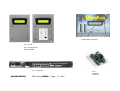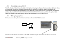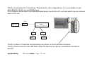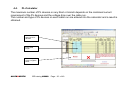
1
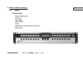
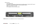
iDR training.
iDR training
CP/LP 29/01/08
Start 09.30. End 16.00. 6 ½ hrs
Requirements
To be supplied by trainee
• Laptop or PC running Windows 98, 2000, XP with Ethernet card. The trainee must have admin
rights in order to manipulate IP addresses and add/remove software.
• Allen & Heath iDR System Manager software. The latest version can be downloaded from the
Allen & Heath website at: http://www.idrseries.com/system_manager.asp
To be supplied by training host
• iDR hardware
The trainer will require the following to demonstrate how the various parts of the system interconnect:
o iDR-8 x2
o iDR-IN expander
o iDR-OUT expander
o iDR-Switch
o 2x PL-4
o Cat 5 network cables (2m) x6
ALLEN&HEATH
iDR training JAN08
Page - 1 - of 49
The following will be required for each trainee:
o
o
o
o
iDR-8 x1
PL-4 x2
PL-5 x2
Cat 5 network cables (2m) x3
• Audio
The following will be required for each trainee:
o Stereo source x2. CD player (each with a different CD) with cabling to XLR i/p on iDR
o Powered loudspeakers x3 (x2 will suffice) with cabling from XLR o/p on iDR
• Documentation and software
o
o
o
o
o
o
o
Allen & Heath iDR System manager software
iDR training .pdf
iDR sales guide .pdf
iDR sales guide Power Point slide show
Getting Started
Trouble shooting .pdf
Quick Tips
• Other hardware
o Projector and screen. To show the iDR Training .pdf and Sales Guide Power Point slide
show.
ALLEN&HEATH
iDR training JAN08
Page - 2 - of 49
1. Introduction
10 min 09.30
• Matrix
The heart of an iDR-8 and iDR-4 is a 16x16 matrix.
• Fixed Architecture DSP
All 16 i/p and all 16 o/p channels have full processing racks permanently loaded. The three big
advantages of this are:
1. Eliminates the need for the programmer to have to assign processing.
2. Eliminates variance in latency between channels.
3. System never runs out of processing power.
• Expandable system
Combinations of iDR-4 / iDR-8, input expanders and output expanders can be chained and looped.
An existing system can be added to or even subtracted from.
• Remote control
There are many ways of controlling the system remotely. We offer a wide range of wall plates, infra
red controllers, fader panels, switch units, rotary panels, LCD displays and custom GUIs (for use on
the client’s PC), in our PL range of controllers.
ALLEN&HEATH
iDR training JAN08
Page - 3 - of 49
• External control
The iDR system can also be controlled by MIDI, AMX, Crestron and RS232 serial commands as
well as connections from third party switches and relays.
This remote control is two way as the iDR can transmit control data.
• System Manager programming software
The system is programmed using our System Manager software. The latest version is always
available from our website as are older versions.
The software runs on a PC or laptop (not MAC compatible) and contains virtual simulations of the
hardware components in the system. The software can be run offline and an entire system can be
programmed and demonstrated without the need to purchase any hardware.
ALLEN&HEATH
iDR training JAN08
Page - 4 - of 49
2. iDR-4 / iDR-8 Hardware
2.1.
15 min
iDR-8
• Front panel
:
:
:
:
:
:
:
Removable cover
Softkeys
Soft LEDs
Label area
LCD
Headphone socket with level trim
Rack ears
ALLEN&HEATH
iDR training JAN08
Page - 5 - of 49
Remove cover
: Code Update button
: Front RS232. Code update and serial control. Front/Rear button. Indicator LED. This port
needs to be activated from within the System Manager software.
: LEDs Slave, Ext Sync Lock, 96k*
: LCD navigation buttons and Menu button
*NOTE: 96kHz is not available due to lack of customer demand.
ALLEN&HEATH
iDR training JAN08
Page - 6 - of 49
• Rear panel
: AC 100 – 240V ~
: RS232 (Modem)
: MDI/X switch. If Link LED does not light, operate this switch. It allows use of straight or
crossover cable.
: TX, Link LEDs
: Network port
: MIDI. This port needs to be activated from within the System manager software.
: Rear RS232 Sysnet port. Indicator LED. This port needs to be activated from within the
System manager software.
: PL-ANET. This port needs to be activated from within the System manager software.
: DR-LINK
: AUDIO IN
: AUDIO OUT
: Analog audio. 8x balanced XLR in/out 2x balanced ¼” jack in/out
Total i/o = 10 IN, 10 OUT
ALLEN&HEATH
iDR training JAN08
Page - 7 - of 49
2.2.
iDR-4
• Front panel
:
:
:
:
:
Removable cover
Softkeys
Soft LEDs
Label area
LCD
No headphone socket with level trim
: Rack ears
ALLEN&HEATH
iDR training JAN08
Page - 8 - of 49
Remove cover
: Code Update slide switch
No front RS232.
No LEDs for Slave, Ext Sync Lock, 96k*
: LCD navigation buttons and Menu button
*NOTE: 96kHz is not available due to lack of customer demand.
ALLEN&HEATH
iDR training JAN08
Page - 9 - of 49
• Rear panel
:
:
:
:
:
:
:
:
:
:
:
AC 100 – 240V ~
RS232 (Modem). This port needs to be activated from within the System manager software.
MDI/X switch
TX, Link LEDs
Network port
No MIDI
Rear RS232 Sysnet port. Indicator LED. This port needs to be activated from within the
System manager software.
PL-ANET. This port needs to be activated from within the System manager software.
DR-LINK
AUDIO IN
AUDIO OUT
Analog audio. 2x balanced XLR in, 4x balanced ¼” jack in
4x balanced XLR out, 2x balanced ¼” jack out
Total i/o = 6 IN, OUT
ALLEN&HEATH
iDR training JAN08
Page - 10 - of 49
• Monitor system
Both the iDR-4 & iDR-8 have two balanced ¼” jack sockets for Monitor L & R IN and Monitor L & R
OUT.
The signal path can be monitored from:
Input channel
o Pre/post Delay
o Pre/post Parametric EQ
o Side Chain Filter
o Pre/post Gate/Comp
o Pre/post Fader
Output channel
o Pre/post Delay
o Pre/post Parametric EQ
o Pre/post Fader
o Pre/post Limiter
The monitor source can be selected in the System manager software or mapped to your computer
mouse. When mapped to the mouse, you can hold the mouse cursor over the part of the signal chain
that you want to listen to.
The monitor jack outputs can either feed local monitor amplifiers or connect to the monitor input jacks
on another iDR. This allows the monitor buses of several iDRs to ripple through.
The monitor jacks can be patched into the matrix giving a total i/o count of 10 x 10 for the iDR-8 and 6
x 6 for the iDR-4.
ALLEN&HEATH
iDR training JAN08
Page - 11 - of 49
3. Plugging up
3.1.
30 min
Single unit
An iDR-8 or iDR-4 can operate as a single stand alone unit.
3.2.
Daisy chain
The audio from the first iDR unit in the chain is transferred to the following units via the A&H digital
audio buss in a unidirectional stream. This CAT5 connection carries a maximum of 8 channels at any
moment. There can be a different combination of 8
channels in each of 250 available presets.
Many iDR units can be chained and iDR-8 can be
mixed with iDR-4 in a combined system.
Each iDR unit runs its own separate System
manager software session and each unit is
programmed individually.
In a chain, the first unit
automatically becomes
the sync master.
ALLEN&HEATH
iDR training JAN08
Page - 12 - of 49
3.3.
Loopback
If the digital audio output of the last unit in a chain is connected to the digital audio input of the first unit
in the chain, any input in the system can be routed to any output in the system.
When looping the
audio, you need to
designate one unit to
be the master.
ALLEN&HEATH
iDR training JAN08
Page - 13 - of 49
3.4.
iDR-IN & iDR-OUT Expanders
An input expander has 8 XLR inputs.
An output expander has 8 XLR outputs.
Expander units terminate the system – it is only possible to have 1x input expander and 1x output
expander in any system.
It is not possible to loop audio when using
expanders.
iDR Link gives
metering data for the
expander LEDs and
control over the
input expander
preamps.
ALLEN&HEATH
iDR training JAN08
Page - 14 - of 49
3.5.
DR-switch
An iDR-switch, connects to DR-Link. If expanders are used in the system, these connect after the DRswitch.
Up to three DR-switch units can be connected to any iDR-8 or iDR-4. Each DR-switch has 24 switch
connections and 16 DC outputs supplying +10V 500mA or +24V 200mA.
A total of 72 switches and 48 logic outputs are available to each iDR unit.
PL-2 Remote wall-plate is designed & packaged specifically for use with iDR Switch – uses two logic
DC outputs from iDR-Switch for tri-colour LED operation, or a single output for simple LED on/off.
ALLEN&HEATH
iDR training JAN08
Page - 15 - of 49
4. PL-Anet
4.1.
15 min
PL-family
PL-6
8x fader
16 button
24 LED
PL-1, 2, 3
PL-10
8x rotary
16 button
24 LED
PL-4 with
PL-5 IR
remote
ALLEN&HEATH
iDR training JAN08
Page - 16 - of 49
Custom GUI for user PC
PL-7 on left.
PL-7 on right shown
with PL-4 fitted
PL-9 7 way hub
ALLEN&HEATH
iDR training JAN08
Page - 17 - of 49
PL-8
4x switch
4x DC o/p
4.2.
Constantly scanned Cat 5
The PL-Anet port has to be activated in the System manager software Communication Options. Once
it is selected, the port is constantly scanned for PL devices. PL devices, when connected, are
automatically detected and addressed. As an example: if you have four PL-3 connected, the iDR will
address them as PL-3 01, PL-3 02, PL-3 03, PL-3 04. If PL-3 03 is removed from the system (the
cable run needs to be made good), the iDR will re-address PL-3 04 as PL-3 03.
4.3.
Wiring topographies
PL devices are daisy chained. Each unit has an IN and OUT RJ45 socket.
iDR -8 / 4
PL-4
Root
PL-4
The Root is the direct connection to the iDR unit Pl-Anet port. Simulators are shown on screen.
ALLEN&HEATH
iDR training JAN08
Page - 18 - of 49
The PL-9 hub allows for 7x branches. This allows for star configurations. It is not possible to loop.
Each Branch has its own re-settable fuse.
PL-9 Outputs can be used to provide dedicated plug-in points for a PL remotes which may be removed
when not in use
Root
iDR -8 / 4
PL-4
A
PL-4
PL-6
B
PL-9
Branch
C D E F G
PL-8
PL-10
The PL-9 offers x7 branches and simulators are shown on Root and their branches.
The PL-9 hub connects to the iDR Root. Other PL devices can also be connected to the Root if
desired.
ALLEN&HEATH
iDR training JAN08
Page - 19 - of 49
4.4.
PL-Calculator
The maximum number of PL devices on any Root or branch depends on the combined current
requirement of the PL devices and the voltage drop over the cable run.
The number and type of PL devices on each cable run are entered into the calculator and a result is
obtained.
Enter number
and type of PL
devices
Enter cable
length
This example
gives a negative
result
ALLEN&HEATH
iDR training JAN08
Page - 20 - of 49
Due to the nature of the spread sheet calculation, sometimes a negative result can be given when the
system design is actually ok.
If a negative result is given, use the Solver. This will give a valid result.
Tools
The Solver
Valid result
Note: The Solver function may not be enabled on your PC. If so then follow the Solver instructions given
in the PL- Calculator.
ALLEN&HEATH
iDR training JAN08
Page - 21 - of 49
4.5.
PL-designer and PL-client
PL-designer is a bitmap based program that allows you to drag and drop various controls such as
faders, meters, switches etc onto a custom background. These bitmap images are linked to controls
within the iDR system.
Custom
background
LCD display
Faders
Meters
Switches
Once the GUI is designed in PL-designer, the non editable user version, called PL-client is loaded onto
the user’s PC. Multiple PL-client users can be connected to the iDR system and each can have a
different GUI.
PL-designer is included in the iDR sytem manager software bundle.
PL-client needs to be registered via our website for each user PC. This is free of charge.
ALLEN&HEATH
iDR training JAN08
Page - 22 - of 49
Break 10.40
10 min
ALLEN&HEATH
iDR training JAN08
Page - 23 - of 49
5. iDR System manager software
5.1.
20 min 10.50
Open the software
ALLEN&HEATH
iDR training JAN08
Page - 24 - of 49
5.2.
The software bundle Show on projector screen. Open each item and briefly discuss
- iDR-4_label
- iDR-8_label
- iDR MIDI Control Protocol
- iDR PL Calculator V1.30.
- iDR Softwre Release Notes
- iDR Sys-Net Control Protocol
- iDR System Manager
- iDR System Manager Help
- iDR Telnet Control Protocol
- PL-5 IR Protocol
- PL-Client
- PL-Designer
- PL-Designer Release Notes
- Read me
These last three icons - Update iDR Unit Softwre, are not required from software version 3.20
onwards. They accomplish the software update via Hyperterminal. From version 3.20, the update
procedure is accomplished from the File menu and is very much faster and easier than the older
method. HyperTerminal is required to update to 3.20.
ALLEN&HEATH
iDR training JAN08
Page - 25 - of 49
5.3.
Basis of the System Manager software
Configuration file.
• An entire setup is called a ‘Configuration’. Many Configurations can be stored on a PC or
laptop and as they are small files they can be easily emailed. We will refer to a Configuration
as .cfg
• .cfg files can be opened and edited on a PC/laptop that is not connected to an iDR unit. This
means that system design and programming can be done and demonstrated without hardware.
• An iDR unit can hold a single .cfg
• When connecting a PC/laptop to an iDR unit, you ‘read’ & see the .cfg that is in the iDR.
• To dump a new .cfg into the iDR, you recall one from those stored on the PC/laptop. Open the
desired .cfg on the computer and recall any preset. The new .cfg is now loaded into the iDR
and the old .cfg is wiped. It is strongly advised that you always save the .cfg from an iDR to
your PC/laptop before loading a new one.
Preset.
• The .cfg has the capacity to store up to 250 individual scenarios or snapshots called presets.
• All parameters are stored in presets except channel names, stereo linking of channels and
scheduled events which are stored globally in the .cfg.
• All parameters (EQ, routing, level etc) must be saved in a preset memory or will be lost when
another preset is recalled.
ALLEN&HEATH
iDR training JAN08
Page - 26 - of 49
6. Programming
40 min
6.1. Overview of GUI Show on projector screen. It may be necessary to click View in order to view
the input and output channels.
• Inputs
There are 16 input channels in the DSP matrix. From the bottom of a channel strip we have:
: Strip number
: Write on strip. Double click this and name the channel.
: Polarity
: Mute
: Level in dB
: Fader/meter
Point out the Source, EQ, gate and Comp buttons at the top of the strip. Click on All to show the
components of a channel strip in one window.
: Source. The dropdown menu allows you to map various physical and digital sources to
the channel strip
: Delay.
: EQ. Four band parametric.
: Gate. Has access to the shared side chain filter.
: Comp. Has access to the shared side chain filter.
: Output routing
: Group fader assignment
: Fader/meter
ALLEN&HEATH
iDR training JAN08
Page - 27 - of 49
• Outputs
There are 16 output channels in the DSP matrix. From the bottom of a channel strip we have:
: Strip number
: Write on strip. Double click this and name the channel.
: Limiter
: Polarity
: Mute
: Level in dB
: Fader/meter
Point out the EQ, and All buttons at the top of the strip. Click on All to show the components of a
channel strip in one window.
: Delay.
: EQ. Eight band parametric with the option of linking bands 1-2 & 7-8 as crossover filters,
each with a choice of standard filter types.
: Input routing
: Group fader assignment
: Fader/meter
: Limiter
ALLEN&HEATH
iDR training JAN08
Page - 28 - of 49
• Hardware simulators
: Click View to see the range of hardware simulators available.
: PL simulators will only be available if they are included in the configuration you are viewing
offline, they must be activated in File/Preferences: select one that includes PL-Anet, then
repeat File/Preferences to choose type and number of devices.
: The simulators all operate in real time with push buttons, rotaries, faders and LEDs.
ALLEN&HEATH
iDR training JAN08
Page - 29 - of 49
• Toolbar
: New Opens new session of System manager, either with an offline simulated iDR-8 / 4 or
any online iDR unit.
: Open Configuration An iDR unit only holds a single.cfg. This icon allows you to open
.cfg files stored on your PC/laptop.
: Archive Configuration Either save to PC/laptop a .cfg from a connected iDR unit or save
to PC/laptop a .cfg that you are editing offline.
: Recall iDR Preset Choose and recall a preset.
: Preset Manager Probably the most important window, and one that should remain onscreen during programming. It is from this window that parameters are stored and presets
are created. It also allows you to view notes about each preset.
: Routing Matrix
: X/P Grps Assign crosspoints to groups.
: I/P Grps
: O/P Grps
: I/P Delay
ALLEN&HEATH
iDR training JAN08
Page - 30 - of 49
: O/P delay
: Ducker
: Automatic Mic Mixer
: Pager
: LCD Settings Display setup
: Set Time At the time of writing, with software version 3.5xx the real time clock has no
auto adjustment for daylight saving.
: Scheduled Events
: Soft Keys Assign soft keys on iDR front panel and up to three switch boxes.
: Soft LEDs Assign soft keys on iDR front panel, up to three switch boxes, input expander
and output expander.
: Preset Recall X-Fade Time In each preset, you can determine the cross fade time when
that preset is recalled from any previous preset.
: Select Stereo Channels
ALLEN&HEATH
iDR training JAN08
Page - 31 - of 49
6.2. Preset Manager window
Two of the main functions of the Preset manager window are to create presets and to store
parameters and changes.
• Select devices to add / Contents / Update
To save changes it is necessary to select the device to be worked on – in this example it is the
Inputs, Mutes and Groups – and Add it to the Contents list.
ALLEN&HEATH
iDR training JAN08
Page - 32 - of 49
After parameters have been set – levels or EQ for instance – it is necessary to highlight the device in
the Contents list and click Update.
ALLEN&HEATH
iDR training JAN08
Page - 33 - of 49
• Power-up preset
The .cfg file contains 250 user programmable presets. If the iDR unit is to be powered off then on
again, it needs to be instructed which preset to activate on power up. Only a single preset can be
selected to be recalled on power up.
If no preset is selected to be recalled on power up, the iDR will boot in a fixed, non user assignable
preset called ‘Default’. It is then necessary to connect a PC/laptop running System manager
software and recall the desired preset.
ALLEN&HEATH
iDR training JAN08
Page - 34 - of 49
6.3. Routing Matrix
• Switch Matrix
The Routing Matrix allows connection of inputs to outputs by clicking the cross points in the Switch
Matrix tab.
Routing Matrix icon
I/P 5 routed to O/P 4
Switch matrix tab
ALLEN&HEATH
iDR training JAN08
Page - 35 - of 49
• Preset Select
When cross point routings have been selected, it is necessary to go to the Preset Select tab.
In the Preset Select tab, clicking on a cross point makes it either Green = armed and ready to be
saved or Grey = unarmed and the setting will not be saved.
I/P 5 to O/P 4 crosspoint is
green.
This routing can now be saved
by updating the Routing matrix
in the preset manager window.
ALLEN&HEATH
iDR training JAN08
Page - 36 - of 49
7. Programming Modules
60 min
The trainees should now work through printed copies of the programming modules, and program the
training configuration.
• Programming Module 1 Set up a new configuration
• Programming Module 2 Source selection
• Programming Module 3 Programming a PL-4 & PL-5
ALLEN&HEATH
iDR training JAN08
Page - 37 - of 49
Lunch 12.50
40 min
ALLEN&HEATH
iDR training JAN08
Page - 38 - of 49
8. Direct connection to PC
50 min 13.30
8.1. TCP/IP explained.
• Transmission Control Protocol / Internet Protocol
These are languages by which network-able equipment such as computers, printers and iDR
communicate, commonly known as Ethernet or network. Each device on a network has its own
address. The address has four parts and we will compare them to country, city, street and house
number.
Country
City
Street
House
IP address
192
168
0
1
Subnet mask
255
255
0
255
The Subnet mask determines which numbers are house numbers. In this example, all numbers
corresponding to 255 are country, street etc. Numbers corresponding to 0 are house numbers. This
allows up to 999 house numbers or devices on the network. A larger network can be set up by
having a subnet mask of 255.255.0.0. This would allow 999,999 devises on the network.
ALLEN&HEATH
iDR training JAN08
Page - 39 - of 49
192.168.0.1 is the factory default IP address of an iDR unit. The first three numbers are an accepted
international standard.
The network relies on all devices being in the same country, city and street – however – they all
have to have different house numbers.
A typical network would have addresses such as: 192.168.0.1 PC #1
192.168.0.2 PC #2
192.168.0.3 PC #3
192.168.0.4 Printer #1
192.168.0.5 Printer #2
192.168.0.6 Scanner
Small company network like this have IP addresses allocated automatically by a server. If you are
going to connect direct from a PC/laptop to an iDR, you need to ensure that the IP address of the
PC is compatible with the iDR. The PC IP address will have to be 192.168.0.2 – or any number
other than 1 (which is the iDR).
ALLEN&HEATH
iDR training JAN08
Page - 40 - of 49
• The PC/laptop
a) Start / settings or control panel / Network Connections / LAN or local connections
b) Open Local Area Connection / click Properties
c) Highlight Internet Protocol
[TCP?IP]
d) Select Use the following
IP address
e) Enter 192.168.0.3 (the last
number can be anything
other than 1 because 1 is
used by the iDR).
f) Click OK
Note: Some computers
require a restart in order to
activate the new IP address
ALLEN&HEATH
iDR training JAN08
Page - 41 - of 49
• The iDR front panel menu
DHCP
The iDR is capable of receiving automatic IP addresses from a server on a network. Out of the box,
the iDR is set with the static IP address 192.168.0.1 to facilitate quick connection with PC/laptop.
DHCP (Dynamic Host Configuration Protocol) is a set of rules used by devices on a network to allow
them to request and accept an IP address from a server. Out of the box, the iDR DHCP setting is NO
(off).
If the iDR is to be used on a network where IP addresses are issued by a server, DHCP must be set to
YES (on).
a) Hold the front panel Menu button until Setup menu *1 shows.
b) Scroll down to Setup menu *5 Network setup.
c) Scroll to menu *5.1 DHCP Setup.
d) Set DHCP to YES for automatic IP address from server or NO for
manual IP address.
ALLEN&HEATH
iDR training JAN08
Page - 42 - of 49
iDR IP address
The default IP address in the iDR unit can be changed.
a) Hold the front panel Menu button until Setup menu *1 shows.
b) Scroll down to Setup menu *5 Network setup.
c) Scroll to menu *5.1 DHCP Setup.
d) Set DHCP to YES for automatic IP address from server or NO for
manual IP address.
e) Scroll to menu *5.2 Set IP Addr
f) Enter the desired IP address. In this example we are changing the last
digit from 1 to 2 as if there are two iDR units on a network.
g) Scroll to menu *5.3 Set Sub-Net
h) Scroll to menu *5.3 and set the Subnet mask to 255. 255. 255.0
ALLEN&HEATH
iDR training JAN08
Page - 43 - of 49
8.2. Plug up the iDR-8, 2x audio sources, 2x PL-4
After
completion
of
the
three
programming modules, you will have a
.cfg that can control two audio sources
into two rooms.
We will now connect our PC / laptop to
an iDR system, open the .cfg and see
how the system operates. NB MDIX
switch pressed ‘in’ to allow use of noncrossover network cable.
• PC/laptop network port to iDR network
port
• PL-Anet to Zone 1 PL-4 IN then OUT
to Zone 2 PL-4 IN
• Stereo source #1 L-R to i/p XLR 1-2
• Stereo source #2 L-R to i/p XLR 3-4
• iDR o/p 1 to Zone 1 powered speaker
(using only the left o/p for this demo)
• iDR o/p 3 to Zone 2 powered speaker
ALLEN&HEATH
iDR training JAN08
Page - 44 - of 49
9. Advanced communications
20 min
9.1. Remote connection over the Internet
The advised method of connecting to a remote iDR is via the internet. Other methods such as VPN
(Virtual Private Network) can open up security issues.
The engineer is connected
to the internet. Open iDR
System Manager and enter
the Wide Area Network IP
address of the client’s
ADSL router.
The iDR protocol carries an
identity 51321.
Program the ADSL router
to forward any incoming
traffic with this identity to the iDR. This is called ‘port forwarding’. Here are the IP addresses: -
ALLEN&HEATH
iDR training JAN08
Page - 45 - of 49
9.2. RS232 and Telnet
• Our designers advise that Telnet is a less than ideal method of connecting. However, Telnet
protocol is provided in the System Manager bundle.
• RS232 serial connection running System Manager Software is very slow. Connection is more
cumbersome than network connection or internet connection.
• RS232 serial control from third party devices is supported. This is bi-directional. The iDR can
receive serial commands and transmit serial commands. NB. ‘polling’ of the iDR unit for current
status is not supported, generally level, mute, preset, changes are transmitted. AMX ‘In Concert’
programming shortcuts are provided via the website.
9.3. MIDI
• MIDI control protocol is provided in the System manager bundle.
INTERNET
CLIENT’s LOCAL AREA NETWORK
Wide Area Network
side of ADSL router
LAN side of ADSL
router
Computer
Printer
iDR
82.201.48.55
192.168.0.1
192.168.0.2
192.168.0.3
192.168.0.4
ALLEN&HEATH
iDR training JAN08
Page - 46 - of 49
9.4. Wireless
• Direct connection to an iDR via a wireless network connection allows the operator to adjust EQ
and dynamics whilst freely moving around the venue.
Break 14.40
20 min
ALLEN&HEATH
iDR training JAN08
Page - 47 - of 49
10. Quick reference documents
45 min 15:00
10.1.
iDR Principles
10.2.
Getting Started
10.3.
Cross Fade
10.4.
Monitor ripple through
10.5.
Pager
10.6.
Preset recall on a downstream iDR (slave) unit
10.7.
The PL-Anet system
10.8.
Trouble-shooter
ALLEN&HEATH
iDR training JAN08
Page - 48 - of 49
11. Sales opportunities
20 min
• Power Point presentation
The slide show illustrates many possible applications for iDR.
12. Debrief & questions & Hands-On
ALLEN&HEATH
iDR training JAN08
Page - 49 - of 49
40 min