1
Capture Software
User’s
Guide
A-63054
EASTMAN KODAK COMPANY SOFTWARE LICENSE AGREEMENT
Read the following terms and conditions carefully before using the enclosed software. Use of the software within this package indicates your
acceptance of these terms and conditions. If you do not agree with them, you should promptly return the package in its entirety and your money
will be refunded.
License
1.
Grant of License. Eastman Kodak Company (“Kodak”) grants you a license to use one copy of the enclosed software program(s) (the
“Software”) subject to the license restrictions set forth below.
2.
Restrictions on Use. You may use the software only on one computer at a time. For each additional computer on which the Software is
running at the same time, you will need an additional licensed copy of the software. You may copy the Software as necessary to use the
Software as described above.
3.
Transfer of the Software. You may permanently transfer the Software to another party if the other party agrees to accept the terms and
conditions of this license and you retain no copies of the Software.
4.
Copyright. The Software is owned by Kodak or its suppliers and protected by copyright laws and International treaties. You may not copy
the Software other than as expressly provided in this license. You may not reverse engineer, decompile, or disassemble the Software.
5.
Term. This license is effective until terminated. You may terminate it at any time by destroying the Software together with all copies in any
form. It will also terminate if you fail to comply with any term or condition of this Agreement. You agree upon such termination to destroy the
Software together with all copies in any form.
Limited Warranty
For a maximum period of up to one year, as evidenced by a copy of your purchase receipt, Kodak warrants (i) the Software will perform
substantially in accordance with the accompanying written materials, and (ii) the media on which the Software is furnished will be free from
defects in materials and workmanship under normal use.
Kodak does not warranty that the functions contained in the Software will meet your requirements or that the operation of the Software will be
uninterrupted or error free. You assume responsibility for operation of the Software to achieve your intended results, and for installation, use,
and results obtained from the Software.
KODAK MAKES NO OTHER WARRANTIES OF ANY KIND, EITHER EXPRESS OR IMPLIED, INCLUDING THE IMPLIED WARRANTIES
OF MERCHANTABILITY AND FITNESS FOR A PARTICULAR PURPOSE. Some states and countries do not allow the exclusion of implied
warranties, so the above exclusion may not apply to you. This warranty gives you specific legal rights and you may also have other rights.
Limitations of Remedies
Kodak’s entire liability and your exclusive remedy shall be, at Kodak’s option either (a) the repair or replacement of the Software or any media
not meeting Kodak’s “Limited Warranty” that is returned to Kodak or your dealer with a copy of your receipt, or (b) the return of the price you
paid for the Software, provided you have proof of the purchase price you paid. These remedies are not available if the failure of the Software or
media is the result of misuse, abuse, or a failure to follow the operating instructions in the accompanying written materials.
IN NO EVENT WILL KODAK OR ITS SUPPLIERS OR DEALERS BE LIABLE TO YOU FOR ANY INCIDENTAL OR CONSEQUENTIAL
DAMAGES, INCLUDING ANY LOST PROFITS, LOST SAVINGS, OR OTHER DAMAGES ARISING OUT OF THE USE OR INABILITY TO
USE THE SOFTWARE EVEN IF ADVISED OF THE POSSIBILITY OF SUCH DAMAGES.
Some states and countries do not allow the limitation or exclusion of liability for incidental or consequential damages, so the above limitation
may not apply to you.
General
If the Software was purchased in the United States, this Agreement is governed by the laws of the State of New York. If purchased outside the
United States, this agreement is governed by the laws of the country in which it was purchased.
If you have any questions concerning this Agreement, contact your local KODAK representative.
U. S. Government Restricted Rights
The SOFTWARE and documentation are provided with RESTRICTED RIGHTS. Use, duplication, or disclosure by the Government is subject to
restrictions as set forth in subdivision (b)(3)(ii) of the Rights in Technical Data and Computer Software clause 252.227- 7013. Contractor/
manufacture is Eastman Kodak Company, 343 State Street, Rochester, New York, 14650.
European Community Provisions
If this Software is used within a county of the European Community, nothing in this Agreement shall be construed as restricting any rights
available under the European Community Software Directive, OJ. Eur. Comm. (No. L. 122) 42 (1991).
EASTMAN KODAK COMPANY
ROCHESTER, NEW YORK 14650
Contents
1 Introduction
Product description . . . . . . . . . . . . . . . . . . . . . . . . . . . . . . . . . . . . . . . . . .
Features . . . . . . . . . . . . . . . . . . . . . . . . . . . . . . . . . . . . . . . . . . . . . . . . . .
Lite version for i200 Series Scanners and i50, i60, and i80 Scanners . . . .
Supported scanners . . . . . . . . . . . . . . . . . . . . . . . . . . . . . . . . . . . . . . . . .
System requirements . . . . . . . . . . . . . . . . . . . . . . . . . . . . . . . . . . . . . . . .
Software . . . . . . . . . . . . . . . . . . . . . . . . . . . . . . . . . . . . . . . . . . . . . . . .
Hardware . . . . . . . . . . . . . . . . . . . . . . . . . . . . . . . . . . . . . . . . . . . . . . .
System development . . . . . . . . . . . . . . . . . . . . . . . . . . . . . . . . . . . . . . . . .
Using this manual . . . . . . . . . . . . . . . . . . . . . . . . . . . . . . . . . . . . . . . . . . . .
Terminology . . . . . . . . . . . . . . . . . . . . . . . . . . . . . . . . . . . . . . . . . . . . . . . .
1-1
1-1
1-2
1-3
1-4
1-4
1-4
1-6
1-6
1-6
2 Getting Started with Capture Software
Before you begin . . . . . . . . . . . . . . . . . . . . . . . . . . . . . . . . . . . . . . . . . . . .
Login procedure . . . . . . . . . . . . . . . . . . . . . . . . . . . . . . . . . . . . . . . . . . . .
Using Capture Software . . . . . . . . . . . . . . . . . . . . . . . . . . . . . . . . . . . . . .
Opening an application . . . . . . . . . . . . . . . . . . . . . . . . . . . . . . . . . . . . .
Creating a new batch . . . . . . . . . . . . . . . . . . . . . . . . . . . . . . . . . . . . . .
Opening a batch . . . . . . . . . . . . . . . . . . . . . . . . . . . . . . . . . . . . . . . . . .
Changing to another application . . . . . . . . . . . . . . . . . . . . . . . . . . . . . .
Starting and stopping the scanner in Capture Software . . . . . . . . . . . .
Exiting Capture Software . . . . . . . . . . . . . . . . . . . . . . . . . . . . . . . . . . .
Restarting if a transport time-out occurs . . . . . . . . . . . . . . . . . . . . . . . .
Recovering from a paper jam . . . . . . . . . . . . . . . . . . . . . . . . . . . . . . . .
Calibration . . . . . . . . . . . . . . . . . . . . . . . . . . . . . . . . . . . . . . . . . . . . . . .
3A
2-1
2-1
2-3
2-3
2-4
2-6
2-6
2-7
2-8
2-8
2-9
2-9
Working in Capture Software
The main Capture Software window . . . . . . . . . . . . . . . . . . . . . . . . . . . . 3A-1
Program title bar . . . . . . . . . . . . . . . . . . . . . . . . . . . . . . . . . . . . . . . . . . . 3A-1
Menu bar . . . . . . . . . . . . . . . . . . . . . . . . . . . . . . . . . . . . . . . . . . . . . . . . . 3A-2
File menu . . . . . . . . . . . . . . . . . . . . . . . . . . . . . . . . . . . . . . . . . . . . . . 3A-3
Batch menu . . . . . . . . . . . . . . . . . . . . . . . . . . . . . . . . . . . . . . . . . . . . . 3A-6
View menu . . . . . . . . . . . . . . . . . . . . . . . . . . . . . . . . . . . . . . . . . . . . 3A-14
Changing zoom settings . . . . . . . . . . . . . . . . . . . . . . . . . . . . . . . . . . 3A-15
Document menu . . . . . . . . . . . . . . . . . . . . . . . . . . . . . . . . . . . . . . . . 3A-16
Index menu . . . . . . . . . . . . . . . . . . . . . . . . . . . . . . . . . . . . . . . . . . . . 3A-19
Tools menu . . . . . . . . . . . . . . . . . . . . . . . . . . . . . . . . . . . . . . . . . . . . 3A-22
Scanner menu . . . . . . . . . . . . . . . . . . . . . . . . . . . . . . . . . . . . . . . . . . 3A-24
Page menu . . . . . . . . . . . . . . . . . . . . . . . . . . . . . . . . . . . . . . . . . . . . 3A-33
Options menu . . . . . . . . . . . . . . . . . . . . . . . . . . . . . . . . . . . . . . . . . . 3A-37
Help menu . . . . . . . . . . . . . . . . . . . . . . . . . . . . . . . . . . . . . . . . . . . . . 3A-38
Scanner bar . . . . . . . . . . . . . . . . . . . . . . . . . . . . . . . . . . . . . . . . . . . . . . 3A-39
Default Scanner bar . . . . . . . . . . . . . . . . . . . . . . . . . . . . . . . . . . . . . 3A-39
Extended Scanner bar . . . . . . . . . . . . . . . . . . . . . . . . . . . . . . . . . . . 3A-40
Scanner bar context-sensitive menu . . . . . . . . . . . . . . . . . . . . . . . . . 3A-41
A-63054 February 2004
i
Tool bar . . . . . . . . . . . . . . . . . . . . . . . . . . . . . . . . . . . . . . . . . . . . . . . . .
Using the Tool bar . . . . . . . . . . . . . . . . . . . . . . . . . . . . . . . . . . . . . . .
Tool bar context-sensitive menu . . . . . . . . . . . . . . . . . . . . . . . . . . .
Document title bar . . . . . . . . . . . . . . . . . . . . . . . . . . . . . . . . . . . . . . . . .
Image display area . . . . . . . . . . . . . . . . . . . . . . . . . . . . . . . . . . . . . . . .
Image title bar . . . . . . . . . . . . . . . . . . . . . . . . . . . . . . . . . . . . . . . . . . . .
Image context-sensitive menu . . . . . . . . . . . . . . . . . . . . . . . . . . . . . . . .
Status bar . . . . . . . . . . . . . . . . . . . . . . . . . . . . . . . . . . . . . . . . . . . . . . .
Button bar . . . . . . . . . . . . . . . . . . . . . . . . . . . . . . . . . . . . . . . . . . . . . . .
Button bar context-sensitive menu . . . . . . . . . . . . . . . . . . . . . . . . . . . .
3A-42
3A-43
3A-53
3A-53
3A-53
3A-54
3A-55
3A-56
3A-57
3A-57
3B Working in Capture Software for i50/i60/i80 Scanners
The main Capture Software window . . . . . . . . . . . . . . . . . . . . . . . . . . . . 3B-1
Program title bar . . . . . . . . . . . . . . . . . . . . . . . . . . . . . . . . . . . . . . . . . . . 3B-1
Menu bar . . . . . . . . . . . . . . . . . . . . . . . . . . . . . . . . . . . . . . . . . . . . . . . . . 3B-2
File menu . . . . . . . . . . . . . . . . . . . . . . . . . . . . . . . . . . . . . . . . . . . . . . 3B-3
Batch menu . . . . . . . . . . . . . . . . . . . . . . . . . . . . . . . . . . . . . . . . . . . . . 3B-6
View menu . . . . . . . . . . . . . . . . . . . . . . . . . . . . . . . . . . . . . . . . . . . . 3B-12
Changing zoom settings . . . . . . . . . . . . . . . . . . . . . . . . . . . . . . . . . . 3B-13
Document menu . . . . . . . . . . . . . . . . . . . . . . . . . . . . . . . . . . . . . . . . 3B-14
Index menu . . . . . . . . . . . . . . . . . . . . . . . . . . . . . . . . . . . . . . . . . . . . 3B-17
Tools menu . . . . . . . . . . . . . . . . . . . . . . . . . . . . . . . . . . . . . . . . . . . . 3B-20
Scanner menu . . . . . . . . . . . . . . . . . . . . . . . . . . . . . . . . . . . . . . . . . . 3B-22
Page menu . . . . . . . . . . . . . . . . . . . . . . . . . . . . . . . . . . . . . . . . . . . . 3B-24
Options menu . . . . . . . . . . . . . . . . . . . . . . . . . . . . . . . . . . . . . . . . . . 3B-27
Help menu . . . . . . . . . . . . . . . . . . . . . . . . . . . . . . . . . . . . . . . . . . . . . 3B-28
Scanner bar . . . . . . . . . . . . . . . . . . . . . . . . . . . . . . . . . . . . . . . . . . . . . . 3B-29
Default Scanner bar . . . . . . . . . . . . . . . . . . . . . . . . . . . . . . . . . . . . . 3B-29
Extended Scanner bar . . . . . . . . . . . . . . . . . . . . . . . . . . . . . . . . . . . 3B-30
Scanner bar context-sensitive menu . . . . . . . . . . . . . . . . . . . . . . . . . 3B-30
Tool bar . . . . . . . . . . . . . . . . . . . . . . . . . . . . . . . . . . . . . . . . . . . . . . . . . 3B-31
Using the Tool bar . . . . . . . . . . . . . . . . . . . . . . . . . . . . . . . . . . . . . . . 3B-33
Tool bar context-sensitive menu . . . . . . . . . . . . . . . . . . . . . . . . . . . . 3B-41
Document title bar . . . . . . . . . . . . . . . . . . . . . . . . . . . . . . . . . . . . . . . . . 3B-42
Image display area . . . . . . . . . . . . . . . . . . . . . . . . . . . . . . . . . . . . . . . . 3B-42
Image title bar . . . . . . . . . . . . . . . . . . . . . . . . . . . . . . . . . . . . . . . . . . . . 3B-43
Image
context-sensitive menu . . . . . . . . . . . . . . . . . . . . . . . . . . . . . . . . . . . . . 3B-44
Status bar . . . . . . . . . . . . . . . . . . . . . . . . . . . . . . . . . . . . . . . . . . . . . . . 3B-45
Button bar . . . . . . . . . . . . . . . . . . . . . . . . . . . . . . . . . . . . . . . . . . . . . . . 3B-45
Button bar context-sensitive menu . . . . . . . . . . . . . . . . . . . . . . . . . . . . 3B-45
ii
A-63054 February 2004
3C Working in Capture Software for i200 Series Scanners
The main Capture Software window . . . . . . . . . . . . . . . . . . . . . . . . . . . . 3C-1
Program title bar . . . . . . . . . . . . . . . . . . . . . . . . . . . . . . . . . . . . . . . . . . . 3C-1
Menu bar . . . . . . . . . . . . . . . . . . . . . . . . . . . . . . . . . . . . . . . . . . . . . . . . . 3C-2
File menu . . . . . . . . . . . . . . . . . . . . . . . . . . . . . . . . . . . . . . . . . . . . . . 3C-3
Batch menu . . . . . . . . . . . . . . . . . . . . . . . . . . . . . . . . . . . . . . . . . . . . . 3C-6
View menu . . . . . . . . . . . . . . . . . . . . . . . . . . . . . . . . . . . . . . . . . . . . 3C-13
Changing zoom settings . . . . . . . . . . . . . . . . . . . . . . . . . . . . . . . . . . 3C-14
Document menu . . . . . . . . . . . . . . . . . . . . . . . . . . . . . . . . . . . . . . . . 3C-15
Index menu . . . . . . . . . . . . . . . . . . . . . . . . . . . . . . . . . . . . . . . . . . . . 3C-18
Tools menu . . . . . . . . . . . . . . . . . . . . . . . . . . . . . . . . . . . . . . . . . . . . 3C-21
Scanner menu . . . . . . . . . . . . . . . . . . . . . . . . . . . . . . . . . . . . . . . . . . 3C-23
Page menu . . . . . . . . . . . . . . . . . . . . . . . . . . . . . . . . . . . . . . . . . . . . 3C-25
Options menu . . . . . . . . . . . . . . . . . . . . . . . . . . . . . . . . . . . . . . . . . . 3C-28
Help menu . . . . . . . . . . . . . . . . . . . . . . . . . . . . . . . . . . . . . . . . . . . . . 3C-29
Scanner bar . . . . . . . . . . . . . . . . . . . . . . . . . . . . . . . . . . . . . . . . . . . . . . 3C-30
Default Scanner bar . . . . . . . . . . . . . . . . . . . . . . . . . . . . . . . . . . . . . 3C-30
Extended Scanner bar . . . . . . . . . . . . . . . . . . . . . . . . . . . . . . . . . . . 3C-31
Scanner bar context-sensitive menu . . . . . . . . . . . . . . . . . . . . . . . . . 3C-31
Tool bar . . . . . . . . . . . . . . . . . . . . . . . . . . . . . . . . . . . . . . . . . . . . . . . . . 3C-32
Using the Tool bar . . . . . . . . . . . . . . . . . . . . . . . . . . . . . . . . . . . . . . . 3C-34
Tool bar context-sensitive menu . . . . . . . . . . . . . . . . . . . . . . . . . . . . 3C-42
Document title bar . . . . . . . . . . . . . . . . . . . . . . . . . . . . . . . . . . . . . . . . . 3C-43
Image display area . . . . . . . . . . . . . . . . . . . . . . . . . . . . . . . . . . . . . . . . 3C-43
Image title bar . . . . . . . . . . . . . . . . . . . . . . . . . . . . . . . . . . . . . . . . . . . . 3C-44
Image context-sensitive menu . . . . . . . . . . . . . . . . . . . . . . . . . . . . . . . . 3C-45
Status bar . . . . . . . . . . . . . . . . . . . . . . . . . . . . . . . . . . . . . . . . . . . . . . . 3C-46
Button bar . . . . . . . . . . . . . . . . . . . . . . . . . . . . . . . . . . . . . . . . . . . . . . . 3C-46
Button bar context-sensitive menu . . . . . . . . . . . . . . . . . . . . . . . . . . . . 3C-46
4 Application Setup
Accessing the Application Setup . . . . . . . . . . . . . . . . . . . . . . . . . . . . . . . . 4-1
Opening and setting up applications . . . . . . . . . . . . . . . . . . . . . . . . . . . . . 4-2
Scanner-specific settings . . . . . . . . . . . . . . . . . . . . . . . . . . . . . . . . . . . . . 4-5
DS 1500 and DS 2500 Options
. . . . . . . . . . . . . . . . . . . . . . . . . . . . . 4-5
i200 Series Scanners Options
. . . . . . . . . . . . . . . . . . . . . . . . . . . . . . 4-9
i800 Series Scanners Options . . . . . . . . . . . . . . . . . . . . . . . . . . . . . . 4-14
Application Setup tabs . . . . . . . . . . . . . . . . . . . . . . . . . . . . . . . . . . . . . . . 4-26
Images setup tab . . . . . . . . . . . . . . . . . . . . . . . . . . . . . . . . . . . . . . . . 4-26
Index setup tab . . . . . . . . . . . . . . . . . . . . . . . . . . . . . . . . . . . . . . . . . . 4-35
Output setup tab . . . . . . . . . . . . . . . . . . . . . . . . . . . . . . . . . . . . . . . . . 4-51
5
Patch Setup
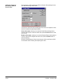
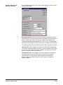
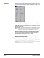
About patch codes . . . . . . . . . . . . . . . . . . . . . . . . . . . . . . . . . . . . . . . . . . .
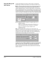
Using the Patch Setup dialog box . . . . . . . . . . . . . . . . . . . . . . . . . . . . . . .
Patch Setup dialog box . . . . . . . . . . . . . . . . . . . . . . . . . . . . . . . . . . . . . . .
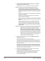
Detecting patch code options . . . . . . . . . . . . . . . . . . . . . . . . . . . . . . . .
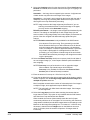
Batch separation options . . . . . . . . . . . . . . . . . . . . . . . . . . . . . . . . . . .
Document separation options . . . . . . . . . . . . . . . . . . . . . . . . . . . . . . . .
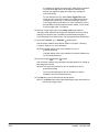
Create attachment options . . . . . . . . . . . . . . . . . . . . . . . . . . . . . . . . . .
A-63054 February 2004
5-1
5-2
5-3
5-3
5-4
5-4
5-5
iii
6
Bar Code/OCR Setup
Bar Code/OCR Setup window for bar codes and OCR . . . . . . . . . . . . . . . 6-1
Bar Code and OCR Setup Tool bar . . . . . . . . . . . . . . . . . . . . . . . . . . . . 6-3
Image context-sensitive menu . . . . . . . . . . . . . . . . . . . . . . . . . . . . . . . 6-4
Scanning an image . . . . . . . . . . . . . . . . . . . . . . . . . . . . . . . . . . . . . . . . 6-6
Drawing and selecting bar code zones . . . . . . . . . . . . . . . . . . . . . . . . . . . 6-8
Bar Code and OCR Setup status bar for bar code zones . . . . . . . . . . . . . 6-9
Setting bar code zone properties . . . . . . . . . . . . . . . . . . . . . . . . . . . . . . 6-10
Using the Properties tab . . . . . . . . . . . . . . . . . . . . . . . . . . . . . . . . . . . 6-12
Testing bar codes . . . . . . . . . . . . . . . . . . . . . . . . . . . . . . . . . . . . . . . . 6-15
Using Separation and Deletion for bar code zones . . . . . . . . . . . . . . 6-16
Displaying bar code values . . . . . . . . . . . . . . . . . . . . . . . . . . . . . . . . . 6-20
Tips for using bar codes . . . . . . . . . . . . . . . . . . . . . . . . . . . . . . . . . . . . . . 6-21
OCR Indexing . . . . . . . . . . . . . . . . . . . . . . . . . . . . . . . . . . . . . . . . . . . . . 6-22
Drawing and selecting OCR zones . . . . . . . . . . . . . . . . . . . . . . . . . . . 6-22
Bar Code and OCR Setup status bar for OCR zones . . . . . . . . . . . . . . . 6-23
Setting OCR zone properties . . . . . . . . . . . . . . . . . . . . . . . . . . . . . . . . . 6-24
Using Separation and Deletion for OCR zones . . . . . . . . . . . . . . . . . 6-25
Tips for using OCR zones . . . . . . . . . . . . . . . . . . . . . . . . . . . . . . . . . . . . 6-27
Disclaimers . . . . . . . . . . . . . . . . . . . . . . . . . . . . . . . . . . . . . . . . . . . . . . . . 6-27
General Bar Code and OCR Properties . . . . . . . . . . . . . . . . . . . . . . . 6-28
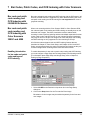
7 Bar Codes, Patch Codes, and OCR Indexing with Color Scanners
Bar code and patch code reading and OCR indexing with
i50/i60/i80 Scanners . . . . . . . . . . . . . . . . . . . . . . . . . . . . . . . . . . . . . . . .
Bar code and patch code reading and OCR indexing with Color
Scanners 3590C and 4500 . . . . . . . . . . . . . . . . . . . . . . . . . . . . . . . . . . .
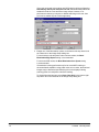
Enabling binarization for bar code and patch code reading and
OCR indexing
..........................................
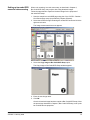
Setting up bar code/OCR zones for color scanning . . . . . . . . . . . . . .
Bar code and patch code reading and OCR indexing with i200 Series
Scanners
...............................................
Bar code and patch code reading and OCR indexing with i800 Series
Scanners
...............................................
8
7-1
7-1
7-3
7-4
7-5
Blank Page Setup
Using the Blank Page Setup dialog box . . . . . . . . . . . . . . . . . . . . . . . . . .
Blank page separator option . . . . . . . . . . . . . . . . . . . . . . . . . . . . . . . . .
Batch separation option . . . . . . . . . . . . . . . . . . . . . . . . . . . . . . . . . . . .
Document separation options . . . . . . . . . . . . . . . . . . . . . . . . . . . . . . . .
Create attachment options . . . . . . . . . . . . . . . . . . . . . . . . . . . . . . . . . .
Blank page separation with i800 Series Scanners . . . . . . . . . . . . . . . . . .
Blank Page Setup for i50/i60/i80 Scanners and i200 Series Scanners . . .
Blank page separator option . . . . . . . . . . . . . . . . . . . . . . . . . . . . . . . . .
Batch separation option . . . . . . . . . . . . . . . . . . . . . . . . . . . . . . . . . . . .
Document separation options . . . . . . . . . . . . . . . . . . . . . . . . . . . . . . . .
Create attachment options . . . . . . . . . . . . . . . . . . . . . . . . . . . . . . . . . .
iv
7-1
8-1
8-2
8-2
8-2
8-2
8-3
8-4
8-5
8-5
8-5
8-5
A-63054 February 2004
9A Setting Up Page Properties
About Page Setup . . . . . . . . . . . . . . . . . . . . . . . . . . . . . . . . . . . . . . . . . . 9A-1
Using Page Setup with low volume, mid-volume, and high volume
scanners
. . . . . . . . . . . . . . . . . . . . . . . . . . . . . . . . . . . . . . . . . . . . . . 9A-1
Scanner-specific page properties . . . . . . . . . . . . . . . . . . . . . . . . . . . . . . 9A-6
Additional page properties for the Scanner 1500 and Scanner 2500 . 9A-6
Additional page properties for mid-volume scanners . . . . . . . . . . . . . . 9A-8
Additional page properties for color scanners . . . . . . . . . . . . . . . . . . . 9A-9
Using Page Setup with the i800 Series Scanners . . . . . . . . . . . . . . . . . 9A-11
Zone processing . . . . . . . . . . . . . . . . . . . . . . . . . . . . . . . . . . . . . . . . 9A-17
Using Image Setup with low volume, mid-volume, and high volume
scanners
. . . . . . . . . . . . . . . . . . . . . . . . . . . . . . . . . . . . . . . . . . . . 9A-18
Filters tab . . . . . . . . . . . . . . . . . . . . . . . . . . . . . . . . . . . . . . . . . . . . . 9A-18
Check tab
. . . . . . . . . . . . . . . . . . . . . . . . . . . . . . . . . . . . . . . . . . . 9A-25
Mask tab
. . . . . . . . . . . . . . . . . . . . . . . . . . . . . . . . . . . . . . . . . . . 9A-26
Using Image Setup with the i800 Series Scanners . . . . . . . . . . . . . . . . 9A-29
i800 Series Scanners Filters tab
. . . . . . . . . . . . . . . . . . . . . . . . . . 9A-29
i800 Series Scanners Check tab . . . . . . . . . . . . . . . . . . . . . . . . . . . . 9A-33
i800 Series Scanners Mask tab . . . . . . . . . . . . . . . . . . . . . . . . . . . . 9A-34
i800 Series Scanners Color Dropout tab . . . . . . . . . . . . . . . . . . . . . 9A-36
Using the Merge and Split options . . . . . . . . . . . . . . . . . . . . . . . . . . . . . 9A-37
9B
Setting Up Page Properties for i50/i60/i80 Scanners
About Page Setup . . . . . . . . . . . . . . . . . . . . . . . . . . . . . . . . . . . . . . . . . . 9B-1
Using Page Setup . . . . . . . . . . . . . . . . . . . . . . . . . . . . . . . . . . . . . . . . . 9B-1
Using Image Setup . . . . . . . . . . . . . . . . . . . . . . . . . . . . . . . . . . . . . . . . 9B-5
Filters tab . . . . . . . . . . . . . . . . . . . . . . . . . . . . . . . . . . . . . . . . . . . . . . 9B-5
Color tab . . . . . . . . . . . . . . . . . . . . . . . . . . . . . . . . . . . . . . . . . . . . . . . 9B-6
Check tab . . . . . . . . . . . . . . . . . . . . . . . . . . . . . . . . . . . . . . . . . . . . . . 9B-7
Mask tab . . . . . . . . . . . . . . . . . . . . . . . . . . . . . . . . . . . . . . . . . . . . . . . 9B-8
Color Dropout tab . . . . . . . . . . . . . . . . . . . . . . . . . . . . . . . . . . . . . . . . 9B-9
Using the Merge and Split options . . . . . . . . . . . . . . . . . . . . . . . . . . . . . 9B-10
9C Setting Up Page Properties for i200 Series Scanners
About Page Setup . . . . . . . . . . . . . . . . . . . . . . . . . . . . . . . . . . . . . . . . . . 9C-1
Using Page Setup . . . . . . . . . . . . . . . . . . . . . . . . . . . . . . . . . . . . . . . . . . 9C-1
Using Image Setup . . . . . . . . . . . . . . . . . . . . . . . . . . . . . . . . . . . . . . . . . 9C-7
Filters tab
. . . . . . . . . . . . . . . . . . . . . . . . . . . . . . . . . . . . . . . . . . . . . 9C-7
Check tab . . . . . . . . . . . . . . . . . . . . . . . . . . . . . . . . . . . . . . . . . . . . . 9C-10
Mask tab . . . . . . . . . . . . . . . . . . . . . . . . . . . . . . . . . . . . . . . . . . . . . . 9C-11
Color Dropout tab . . . . . . . . . . . . . . . . . . . . . . . . . . . . . . . . . . . . . . . 9C-13
Using the Merge and Split options . . . . . . . . . . . . . . . . . . . . . . . . . . . . . 9C-14
10 Recovery Procedure . . . . . . . . . . . . . . . . . . . . . . . . . . . . . . . . . . . . . . . . 10-1
11 System Administration
Program Properties . . . . . . . . . . . . . . . . . . . . . . . . . . . . . . . . . . . . . . . . .
User profiles . . . . . . . . . . . . . . . . . . . . . . . . . . . . . . . . . . . . . . . . . . . . . .
User groups . . . . . . . . . . . . . . . . . . . . . . . . . . . . . . . . . . . . . . . . . . . .
Logging in using network user names . . . . . . . . . . . . . . . . . . . . . . . .
A-63054 February 2004
11-1
11-2
11-4
11-5
v
A Installation
Before you begin . . . . . . . . . . . . . . . . . . . . . . . . . . . . . . . . . . . . . . . . . . . . A-1
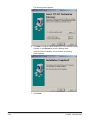
Accessing the Capture Software Setup window . . . . . . . . . . . . . . . . . . . . . A-1
Required TWAIN data source for i50/i60/i80 Scanners . . . . . . . . . . . . A-2
Required TWAIN data source for i200 Series Scanners . . . . . . . . . . . . A-2
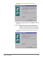
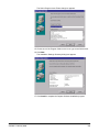
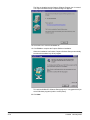
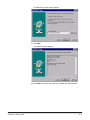
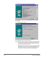
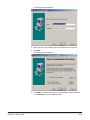
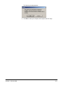
Installing Capture Software . . . . . . . . . . . . . . . . . . . . . . . . . . . . . . . . . . . . A-3
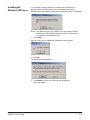
Updating the Windows ASPI layer . . . . . . . . . . . . . . . . . . . . . . . . . . . . . A-13
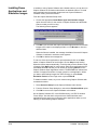
Installing the Scanner Validation Tool (SVT) for i200 Series Scanners . . A-14
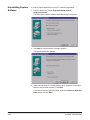
Installing Demo Applications and Emulation Images . . . . . . . . . . . . . . . A-18
Installing Demo Applications only . . . . . . . . . . . . . . . . . . . . . . . . . . . . . . A-19
Uninstalling Capture Software . . . . . . . . . . . . . . . . . . . . . . . . . . . . . . . . A-20
Upgrading your Capture Software installation . . . . . . . . . . . . . . . . . . . . A-23
Index
vi
A-63054 February 2004
1 Introduction
Product description
Kodak Capture Software is a software application that enables all functions of
the entire family of Kodak Scanners and Kodak Digital Science™ Scanners in
both simplex and duplex models.
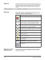
Features
Some features of Capture Software:
• All functions are performed using this software, no special hardware
acceleration is required.
• Fast display in scale to gray of bitonal (i.e., black and white) images.
• Fast deskew, auto-crop, and auto-rotate of color, bitonal, and
grayscale images.
• Auto-delete with or without preview.
• Multi-image display (1, 2, 4, and 8 images can be displayed simultaneously).
• Easy-to-use Scanner bar and Button bar, and a Tool bar that provides tools
to rescan, insert, delete and move pages. It also provides direct access to
threshold and contrast values.
• Programmable Batch Output formats make Capture Software compatible
with a range of imaging systems on the market.
• Pre-defined set of image parameter templates.
• Patch code reading for document separation.
• Bar code reading for automatic indexing.
• Zonal OCR for automatic indexing.
A-63054 February 2004
1-1
Lite version for
i200 Series Scanners
and i50, i60, and
i80 Scanners
The Kodak i200 Series Scanners, Kodak i50 Scanner, Kodak i60 Scanner, and
Kodak i80 Scanner come bundled with the Lite version of Capture Software.
This is a production version that does not require a hardware key. However, all
features are not available.
Upgrade to the full version of Capture Software and receive these additional
features and functionality:
• Software bar code and patch code reading
• Indexing from bar codes, OCR text, or key data entry
NOTE: Only one index field is available in Capture Software Lite. Up to
10 index fields are available in the full version.
• Blank Page Separation
• Automatic Batch and Document Separation
• Auto-deletion of blank images
• Merge and Split of bitonal images
• User profiles
• Software length detection (e.g., flag errors on multifeeds)
• Post-Scanning Toolbar functions (Insert, Rescan, Crop, Blank, Move image,
Copy image [or image area], Split document)
• Calendar Duplex Mode
• Access to all Capture Software Batch Output Formats
(currently over 40 available)
NOTE: Capture Software Lite will not run in full production mode even with an
attached hardware key. You must upgrade to the full version to receive
full functionality.
1-2
A-63054 February 2004
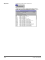
Supported scanners
Capture Software supports the following scanner models:
• Kodak i50 Scanner
• Kodak i60 Scanner
• Kodak i80 Scanner
• Kodak i250 Scanner
• Kodak i260 Scanner
• Kodak i280 Scanner
• Kodak Digital Science Scanner 1500
• Kodak Digital Science Scanner 2500
• Kodak Digital Science Scanner 3500
• Kodak Digital Science Scanner 3510
• Kodak Digital Science Scanner 3520
• Kodak Digital Science Scanner 3590C
• Kodak Digital Science Scanner 4500
• Kodak Digital Science Scanner 5500
• Kodak Digital Science Scanner 7500
• Kodak Digital Science Scanner 7520
• Kodak Digital Science Scanner 9500
• Kodak Digital Science Scanner 9520
• Kodak Digital Science Scanner/Microimager 990
• Kodak Imagelink 500 Scanner
• Kodak Imagelink 900 Scanner
• Kodak Imagelink 923 Scanner
• Kodak i810 Scanner
• Kodak i820 Scanner
• Kodak i830 Scanner
• Kodak i840 Scanner
A-63054 February 2004
1-3
System requirements
Following are the minimum software and hardware requirements to run
Capture Software.
Software
All systems require Windows 98, Windows Me, Windows NT 4.0, Windows
2000, or Windows XP.
NOTE: The i200 Series Scanners are only supported under Windows 98SE,
Windows Me, Windows 2000, and Windows XP.
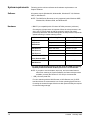
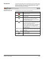
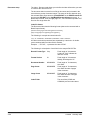
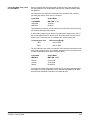
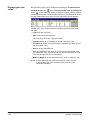
Hardware
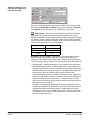
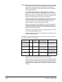
• IBM PC (or compatible) with a Pentium 667 MHz processor (minimum)
Choosing the right processor is important. When the microprocessor is too
slow, your PC cannot keep up with the scanner’s speed, and overall
productivity decreases. See the following table for the processor required for
optimal scanning in certain scanning modes.
Scanner Model
Scanning Mode
Processor Required
i50 Scanner
Black and white
Pentium 667 MHz
i60 Scanner
Grayscale
Pentium 1 GHz*
i80 Scanner
Color
Pentium 1 GHz*
i250 Scanner
Black and white
Pentium 2.5 GHz
i260 Scanner
Grayscale
Pentium 2.5 GHz*
i280 Scanner
Color
Pentium 2.5 GHz*
Color Scanner 3590C
Color
Pentium 1 GHz*
Color
Pentium 1.5 GHz*
Color Scanner 4500
i820 Scanner
i840 Scanner
* For color and grayscale scanning, the PC must have MMX processing
capability and an Intel-based Pentium processor is recommended.
NOTE: If you plan to use the deskew, auto-crop, and auto-rotate features
when color scanning in Capture Software, the fastest microprocessor
available (currently the Pentium IV 2.5 GHz) is recommended.
• 1 GB (<10 msec) hard disk
For color scanning with the i820 Scanner or i840 Scanner, two (2) SCSI
hard disk drives are recommended: one for the operating system and one
for storing the scanned images. Much more disk space will likely be required
for scanned image storage.
1-4
A-63054 February 2004
• 128 MB of RAM
- For color scanning with the i50 Scanner, i60 Scanner, or i80 Scanner,
256 MB of RAM is recommended.
- For color scanning with the i200 Series Scanners, 512 MB of RAM is
recommended.
- For color scanning with the i820 Scanner or i840 Scanner, 512 MB of
RAM is recommended.
• SCSI controller
- An Adaptec 2940 controller is recommended. You can also use an
Adaptec 1542CP controller. Newer SCSI cards such as the Adaptec
19160 or 29160 may also be used.
- For the i800 Series Scanners, an Adaptec 29160 SCSI controller or
equivalent (Ultra-Wide2 SCSI) is required.
• IEEE-1394 (FireWire) controller
For the i200 Series Scanners, a plug-and-play IEEE-1394 (FireWire)
interface is required. Use only the FireWire card and cable that is supplied
with the i200 Series Scanner.
IMPORTANT: The i200 Series Scanner should be the only item plugged in to
the IEEE-1394 (FireWire) card on the host computer.
• Parallel/printer port (with DB25 female connector) for hardware
key installation.
USB ports are not supported.
• Display monitor and graphic controller
Most high-quality displays and graphic controllers are acceptable.
The display resolution should be set to at least 800 x 600.
- For black-and-white scanning, the display monitor should be set to at
least 256 Colors. For color scanning with the Kodak color scanners, set
the display monitor to True Color (24 bit or 16 million colors).
- For color scanning with the i820 Scanner and i840 Scanner, an
AGP (Advanced Graphics Processor) video card with 32 MB of
video RAM is recommended.
A-63054 February 2004
1-5
System development
The Capture Software program was developed by Eastman Kodak Company
and I.R.I.S. Group, Belgium.
Using this manual
This User’s Guide describes the functions and procedures in Capture
Software. Chapters 2 and 3 are directed toward individuals who are
responsible for scanning, manipulating images within a document, and
writing to image batches. These individuals must have a working knowledge of
IBM (or compatible) PCs and the Windows operating environment. In addition
to computer and scanner operations skills, a basic understanding of digital
imaging or image scanning is helpful.
Chapters 4 through 11 and Appendix A are intended for the system
administrator who is responsible for configuring the scanner and
Capture Software.
Differences between the Capture Software products specific to the low,
mid-, and high volume scanners will be identified throughout the manual
where appropriate.
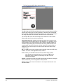
NOTE: Many of the screen examples in this manual were captured using
Capture Software with a Scanner 3500. These examples, except
where noted, also apply to Capture Software support for the Kodak
scanners listed in this chapter.
Terminology
Before you start, it is important to know how document, page, side, image,
and other terms are used in this guide.
Application—you can create an unlimited number of applications with
Capture Software (the actual number of applications allowed depends on
directory limits imposed by the operating system). Applications are
distinguished by the batch and document separation methods used
(e.g., patch codes, document/image counters, etc.), indexing requirements
(e.g., bar code) and Batch Output format requirements. With an application,
you can produce batches of an essentially unlimited number of documents
(up to 999999999) which are used in conjunction with other digital
document management systems and are available in several output
formats (e.g., IMR Alchemy, MO:DCA, eiStream WMS RBE).
Batch—a collection of documents. An application can contain several batches
(each up to 999999999 documents; essentially unlimited). Processing a batch
means converting the batch to a specific output format (e.g., IMR Alchemy,
single-page TIFF, MO:DCA, eiStream WMS RBE) and sending it to a batch
destination folder/subdirectory. Batches can be processed one by one
or together.
1-6
A-63054 February 2004
Document—a paper document is a collection of pages; an electronic
document is a collection of images. A document containing many pages is
called a multi-page document (e.g., a file folder or article). A document
containing only one page is called a single-page document (e.g., a check).
Initially, every document is in paper form and becomes an electronic document
after it is scanned; Capture Software gives every document a unique electronic
document number. This document number is cross-referenced with index data
that can be uploaded to any document management system.
Document index—the document index links search fields (up to 10 search
fields) with the document number of each document. The document index can
be built manually or automatically with bar codes or default values.
Image—the scanner converts sides to images. Every image belongs to a
document with a unique document number. Capture Software gives every
image a sequential number inside its document. One document can contain
up to 999999999 (i.e., essentially unlimited) images. Capture Software
distinguishes between an image coming from the front or rear side of a
page. This allows Capture Software to perform side-specific processing
(e.g., deletion of blank/rear sides) where appropriate.
Capture Software also distinguishes between color, grayscale, and bitonal
(black and white) images and can perform color/grayscale versus bitonal
specific processing.
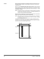
Example: Document 250 contains two double-sided pages and produces an
electronic document number 250, which contains four images (1-4).
Page—a page is always in paper form and is part of a paper document. A
page can produce one image (single-sided page), two images (double-sided
page), or four images (dual-stream; color and bitonal) after scanning.
Side—one page has two sides, front and rear. With single-sided pages, the
rear is blank.
A-63054 February 2004
1-7
2 Getting Started with Capture Software
Before you begin
Before you begin make sure that the scanner is connected to the system and
powered on.
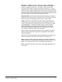
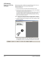
Login procedure
1. Click on Start (usually located in the bottom left corner) on the
Windows desktop.
2. Move the mouse arrow to Programs.
3. Move the mouse arrow to one of the following program icons
(depending on your scanner model):
- Kodak Capture Software for IL and DS Scanners
- Kodak Capture Software for i800 Scanners
- Kodak Capture Software for i50, i60, i80, i200 Scanners
4. Move the mouse arrow to the Capture Software icon.
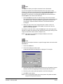
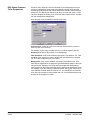
If your system administrator has established user profiles for your
Capture Software installation, you may first be required to log in to
Capture Software.
A-63054 February 2004
2-1
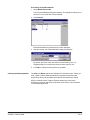
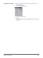
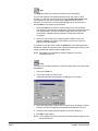
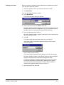
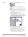
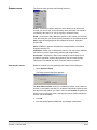
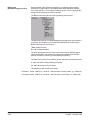
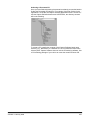
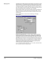
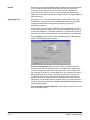
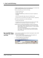
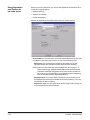
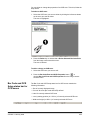
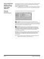
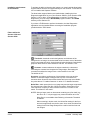
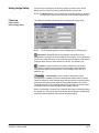
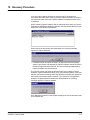
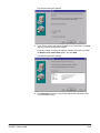
5. Enter your user name and password to complete the login procedure.
The Capture Software Open Application window appears.
2-2
A-63054 February 2004
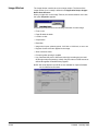
Using Capture
Software
Capture Software provides Production applications and Template applications.
For more information on how to set up these templates, see Chapter 4,
Application Setup.
The sections that follow provide procedures for opening and closing an
application as well as opening and creating a new batch. Chapter 3,
Working in Capture Software, provides detailed information on other
functions you can access from the Capture Software main window.
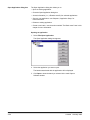
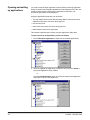
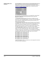
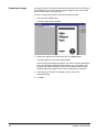
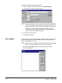
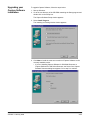
Opening an application
To open an application:
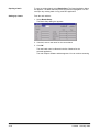
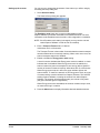
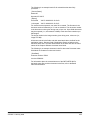
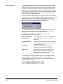
1. Select File>Open Application.
The Open Application dialog box appears. You will see only applications
for which you have privileges.
2. Double-click on the application you want to open or highlight the
application and click Open.
The batches associated with the application appear.
3. Click Open to display the batch you selected.
A-63054 February 2004
2-3
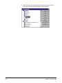
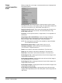
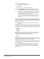
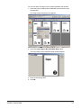
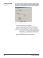
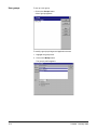
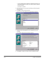
Creating a new batch
To create a new batch, proceed as follows.
From the Open Application window:
1. Select an application where you want the new batch to reside.
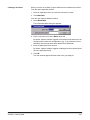
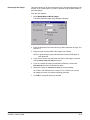
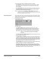
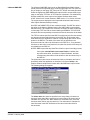
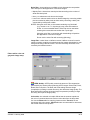
2. Click New Batch.
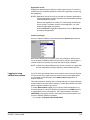
The Create New Batch dialog box appears.
3. Enter a new batch name in the Batch name field.
By default, Capture Software suggests a new batch name based upon the
last batch name created for the application (e.g., if the last batch name is
Batch002, then the new batch name default will be Batch003).
4. Enter the starting document number.
By default, Capture Software suggests a starting document number based
upon the Application Setup.
5. Click OK.
The main window appears with the batch name you assigned.
Depending on your User Profile settings and the Application Setup,
other dialog boxes may appear before the main Capture Software
window appears.
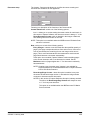
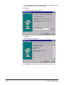
• For i200 Series Scanners, Scanner 1500, Scanner 2500, Scanner
3520DP, or Color Scanner 4500DP when document printing is enabled,
and the i800 Series Scanners, the Set Counter dialog box appears.
2-4
A-63054 February 2004
Enter a starting counter number.
- For the i200 Series Scanners, the number will be downloaded and
printed on the first scanned page.
- For the Scanner 1500 or Scanner 2500, the number will be
downloaded to the scanner and will appear on the scanner’s
LCD display.
- For the Scanner 3520DP or Color Scanner 4500DP, the number will
be downloaded and printed on the first scanned page when document
printing is enabled.
- For the i800 Series Scanners, the number is downloaded and
assigned (and optionally printed) to the first scanned page.
By default, with the exception of i200 Series Scanners, Capture
Software suggests a starting counter based upon the Application Setup.
For i200 Series Scanners, Capture Software keeps track of the counter
across scanned batches and will suggest a starting counter equal to
the counter of the last scanned page + 1. When Capture Software is
restarted, the suggested starting counter is reset to “1.”
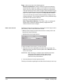
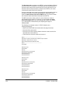
• For high volume and i800 Series Scanners, the Set Image Address
dialog box appears.
Enter the starting image address for the batch. It will be downloaded to
the attached high volume scanner and will appear in the scanner’s LCD
display. Only those image address fields (i.e., Fixed field, Level 3, Level
2, and Level 1) that are applicable to the scanner mode being used can
be modified. By default, Capture Software suggests a starting image
address based upon the Application Setup.
6. Start scanning into the new batch.
A-63054 February 2004
2-5
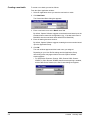
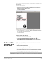
Opening a batch
• To open an existing batch, double-click on the batch you want to open
or highlight it and click Open.
The main window appears and shows the existing batch.
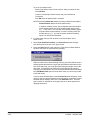
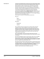
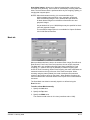
If you are scanning in a multiple scanner environment, and the batch has
already been opened by another workstation, Capture Software will not allow
you to open the batch. Instead, a message similar to the one shown below
will appear.
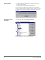
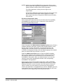
Changing to another
application
• From the main window, select File>Open Application.
The Open Application dialog box appears.
From this dialog box you can open another application.
2-6
A-63054 February 2004
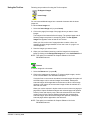
Starting and stopping
the scanner in
Capture Software
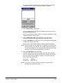
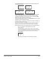
To start the scanner in Capture Software:
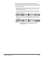
Stop Start
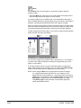
• Click on the green Start button (on the Scanner bar in the Capture Software
main window) or press F7.
- For the i50/i60/i80 Scanners, you first need to place the documents to be
scanned face down in the feeder. The scanner automatically detects the
presence of documents in the feeder and the scanner transport/feeder
starts to run.
You may also place a document on the flatbed. If no documents are in the
feeder and flatbed scanning has been enabled, the scanner will scan the
flatbed. When you scan single sheet documents with the flatbed, place
the documents in the upper left corner of the flatbed (this position is
labeled “0,0” on the flatbed).
- For the i200 Series Scanners, the scanner transport/feeder starts to run.
You may also place a document on the flatbed. If no documents are in the
feeder and flatbed scanning has been enabled, the scanner will scan the
flatbed. When you scan single sheet documents with the flatbed, place
the documents face down with the corner aligned with the arrow.
- For the Scanner 1500 and Scanner 2500, you first need to place the
documents to be scanned in the feeder. The scanner automatically
detects the presence of documents in the feeder and the scanner
transport/feeder starts to run.
For the Scanner 1500, you may also place a document on the flatbed.
If no documents are in the feeder and flatbed scanning has been
enabled, the scanner will scan the flatbed. When you scan single
sheet documents with the flatbed, place the documents in the upper
left corner of the flatbed.
NOTE: Page Setup is configured for auto-cropping and/or deskewing
documents, place the document in the middle of the flatbed platen
and align the top edge with the top edge of the glass.
- For the Scanner 3500, Scanner 3510, Scanner 3520, Color Scanner
3590C, and Color Scanner 4500, the scanner transport/feeder starts
to run.
- For the Scanner 5500, Scanner 7520, and Scanner 9520, the Start button
enables the scanner. You must press the green button on the scanner’s
operator panel to start the scanner transport/feeder.
A-63054 February 2004
2-7
- For the i800 Series Scanners, the Auto-start transport option in the
Scanner Setup dialog determines what the Start button does.
When Auto-Start transport is enabled, the scanner transport and feeder
will automatically run and start scanning.
When Auto-Start transport is disabled, the Start button enables only the
scanner. You must press the green button on the scanner control panel to
start the scanner transport/feeder.
It may take a few seconds to start the scanner the first time because
Capture Software is downloading parameters. Successive starts are faster.
To stop the scanner in Capture Software:
• Click the red Stop button on the Scanner bar of the Capture Software main
window or press F6.
NOTE: The i50 Scanner, i60 Scanner, or i80 Scanner will stop when all
documents in the feeder have been scanned.
Exiting Capture Software
• To exit Capture Software, select File>Exit.
The Capture Software application closes.
Restarting if a
transport time-out
occurs
The scanner stops automatically when you do not scan documents for a
period of time (based upon the time-out period that is set in the Scanner
Setup dialog box).
To restart the feeder and transport, click the green Start button on the
Scanner bar and continue feeding documents. You do not need to restart
Capture Software.
2-8
A-63054 February 2004
Recovering from
a paper jam
Under certain conditions, a paper jam can occur. Follow these steps to clear
the scanner and restart Capture Software.
1. Clear any paper from the scanner by following the guidelines described in
the User’s Guide for the scanner you are using.
2. Make sure that the top and/or bottom of the scanner are completely closed,
if you had to open them to clear the jam.
3. Wait until the scanner is ready (e.g., on the Scanner 3500, the yellow light
is off and the green Ready light has stopped flashing).
NOTE: Check the screen to verify the last complete image you received from
the scanner before the paper jam. Restart scanning from that point.
4. Click the green Start button on the Scanner bar in the main window.
NOTE: For the i200 Series Scanners, the red indicator light remains on until
the scanner is restarted. If the jam was properly cleared, the red
indicator light will go out and the green indicator light will illuminate.
Calibration
Calibration optimizes the optical system of your scanner in order to achieve the
best overall quality of scanned images. Frequent calibration is not needed or
recommended. However, if you do need to calibrate the scanner (for example,
poor image quality), follow the steps below.
1. Clean the imaging guides properly (e.g., see the scanner’s User’s Guide
for procedures).
2. Obtain a proper calibration target.
Use a clean, blank sheet of paper with a matte surface (not glossy). Make
sure that the target is wider than the documents to be scanned. It is best to
use the square calibration target available from Kodak.
NOTE: For the i800 Series Scanners only: You must use the special
black-and-white calibration target provided with the scanner.
3. Select Scanner>Calibration in the Capture Software main window.
NOTES: For the i50, i60, and i80 Scanners and the Scanner 1500 and
Scanner 2500, scanner calibration is not necessary and therefore is
not available through Capture Software.
For the Scanner 5500, Scanner 7520, and Scanner 9520, calibration
is available only through the scanner operator panel and is required
every time the scanner is powered up.
For the Color Scanner 3590C and Color Scanner 4500, select
Scanner>Color Calibration for color image quality issues.
A prompt appears.
4. Place the calibration target in the scanner ADF.
5. Click OK.
A-63054 February 2004
2-9
3A Working in Capture Software
The main
Capture Software
window
This chapter describes how to access and use the various functions of
Capture Software through the tools and menus of the main window.
The main window contains the following elements:
• Program title bar
• Menu bar
• Scanner bar
• Document title bar
• Tool bar
• Image display
• Button bar
• Status bar
Program title bar
A-63054 February 2004
The Program title bar provides the version number of Capture Software that
you are running and the name of the selected scanner. The application name
is also included on the Program title bar.
3A-1
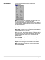
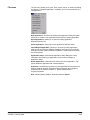
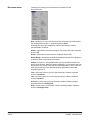
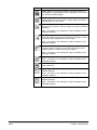
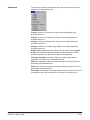
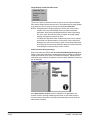
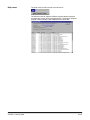
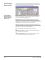
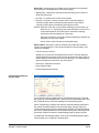
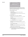
Menu bar
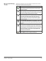
The Menu bar provides the following menu options:
The following summarizes the functions associated with each Capture
Software menu:
File—allows you to open, close, or delete an existing Production or Template
application. In addition, you can create and set up a new application.
Batch—allows you to open an existing batch or create a new batch; and
process current or all available batches.
View—allows you to display 1, 2, 4, or 8 images, fit images to the display
windows regardless of its original size and allows you to enlarge or reduce the
images by a fixed percentage.
Document—provides many options of navigating through the displayed
images of a document and the documents within a batch. You can also create
and delete documents and attach new images to an existing document.
Index—allows you to edit batch, document, and page index fields.
Tools—provides a variety of methods which allows you to manipulate
displayed images.
Scanner—allows you to set up a scanner and to start, stop and calibrate
the scanner.
Page—allows you to set up specific page properties, duplex scanning mode
(classic or calendar), and image setup options.
Options—provides access to hiding or displaying the Tool bar, Status bar,
Button bar, and Scanner bar.
Help—provides version number information about the current installation of
Capture Software.
The following sections provide information on each of these menu options. In
many cases, you can use a keyboard, Tool bar, Scanner bar, or Button bar
shortcut instead of selecting an option from the menu.
Button bar, Scanner bar, and Tool bar summaries are described later in this
chapter. Procedures on how to use a menu option are covered in the following
menu descriptions.
3A-2
A-63054 February 2004
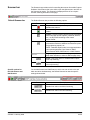
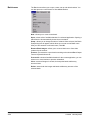
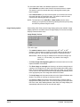
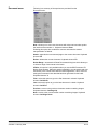
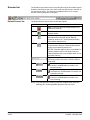
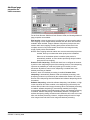
File menu
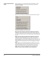
The File menu allows you to open, close, import, export, or delete an existing
Production or Template application. In addition, you can create and set up a
new application.
New Application—accesses the Create New Application dialog box which
allows you to create a new application based upon an existing application.
Open Application—allows you to open an existing application. Keyboard
shortcut: F3
Close Application—closes the current application and open batch.
Import/Export Application—allows you to export (or save) application
settings from one Capture Software installation and import (or load) those
settings to another Capture Software installation. These functions currently
are not supported.
Application Setup—accesses the Application Setup dialog box. More
information about setting up applications can be found in Chapter 4,
Application Setup.
Delete Application—when selected, deletes the current application. You
cannot delete an application that contains batches.
Properties—automatically closes the current application and accesses the
Capture Software Program Properties. More information about Program
Properties can be found in Chapter 11, System Administration —
Program Properties.
Exit—closes Capture Software. Keyboard shortcut: Alt+F4
A-63054 February 2004
3A-3
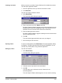
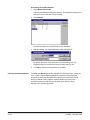
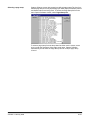
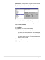
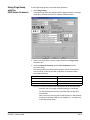
Open Application dialog box
The Open Application dialog box allows you to:
• Open an existing application.
• Close the Open Application dialog box.
• Access information (i.e., a Readme text file) for selected applications.
• Set up a new application—see Chapter 4, Application Setup, for
more information.
• Delete an existing application.
• Create a new batch—see the section entitled “The Batch menu” later in this
chapter for more information.
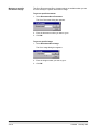
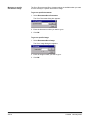
Opening an application
1. Select File>Open Application.
The Open Application dialog box appears.
2. Select the application you want to open.
The batches associated with the application will be displayed.
3. Click Open to show the batch you selected in the main Capture
Software window.
3A-4
A-63054 February 2004
Closing an application
• Select File>Close Application from the main Capture Software window.
Deleting an application
1. Select the application you want to delete.
The batches associated with the application will be displayed.
NOTE: An application cannot be deleted unless all batches are processed
or deleted.
2. Click Delete.
Accessing online application information
1. Select the application you want information about.
2. Click About.
If available, information about the application will appear in a text window.
A-63054 February 2004
3A-5
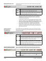
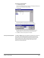
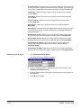
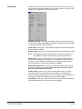
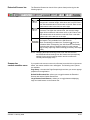
Batch menu
The Batch menu allows you to open, create, set up and delete batches. You
can also process a current batch or all available batches.
New—allows you to create a new batch.
Open—shows a list of available batches for a selected application. Opening a
batch from the list automatically closes the current batch.
Setup—allows you to change the name of a batch. When selected, the Batch
Setup dialog box will appear, which allows you to enter a new Batch name.
After you have entered a new batch name, click OK.
Remove Blank Images—allows you to remove blank rear or front sides
produced by the scanner.
Process—processes the current batch according to the selected Batch Output
Format. Keyboard shortcut: P
Process All—shows all available batches for the current application; you can
select one or more batches to process unattended.
Clear—erases all images in a batch, but keeps the batch subdirectory
structure intact.
Delete—erases both the images and batch subdirectory structure of the
selected batch.
3A-6
A-63054 February 2004
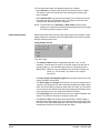
Creating a new batch
When you create a new batch, Capture Software will not disable the scanner.
From the Open Application window:
1. Select an application where you want the new batch to reside.
2. Click New Batch.
From the main Capture Software window:
3. Select Batch>New.
The Create New Batch dialog box appears.
4. Enter a new batch name in the Batch name field.
By default, Capture Software suggests a new batch name based upon the
last batch name created for the application (e.g., If the last batch name is
Batch002, then the new batch name default will be Batch003).
5. Enter the starting document number.
By default, Capture Software suggests a starting document number based
upon the Application Setup.
6. Click OK.
The main window appears with the batch name you assigned.
A-63054 February 2004
3A-7
Depending on your User Profile settings and the Application Setup,
other dialog boxes may appear before the main Capture Software
window appears.
• For the Scanner 1500 or Scanner 2500 and Scanner 3520DP or Color
Scanner 4500DP (when document printing is enabled), and the i800
Series Scanners, the Set Counter dialog box appears.
Enter a starting counter number.
- For the Scanner 1500 or Scanner 2500, the number is downloaded to
the scanner and will appear on the scanner’s LCD display.
- For the Scanner 3520DP or Color Scanner 4500DP, the number is
downloaded and printed on the first scanned page when document
printing is enabled.
- For the i800 Series Scanners, the number is downloaded and
assigned (and optionally printed) to the first scanned page.
By default, Capture Software suggests a starting counter based upon
the Application Setup.
• For high volume and i800 Series Scanners, the Set Image Address
dialog box appears.
Enter the starting image address for the batch. It will be downloaded to
the attached high volume scanner and will appear in the scanner’s LCD
display. Only those image address fields (i.e., Fixed field, Level 3, Level
2, and Level 1) that are applicable to the scanner mode being used can
be modified. By default, Capture Software suggests a starting image
address based upon the Application Setup.
7. Start scanning into the new batch.
3A-8
A-63054 February 2004
Opening a batch
To open an existing batch, select Batch>Open. The Open Application dialog
box appears. The batch that was previously opened is highlighted. You can
now open any existing batch in any production application.
Setting up a batch
From the main window:
1. Select Batch>Setup.
The Batch Setup dialog box appears.
2. If desired, enter a new name for the current batch.
3. Click OK.
The new batch name is reflected in the list of batches for the
selected application.
The main Capture Software window appears. You can continue scanning.
A-63054 February 2004
3A-9
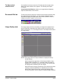
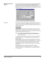
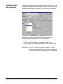
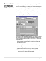
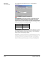
Removing blank images
This option allows you to remove the blank rear or front sides produced by the
scanner. If you use this option, you will be asked to verify the batch delete of
the blank images.
From the main window:
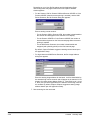
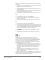
1. Select Batch>Remove Blank Images.
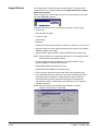
The Remove Blank Images Setup dialog box appears.
2. Enter the document in the batch where you want verification to begin. The
default is 1.
3. Define the byte size threshold of the images to be verified.
NOTE: A good setting for typical business documents is 5000 bytes in
200 dpi bitonal.
4. If you want to remove only the blank rear sides of the images in a batch,
click the Check only rear sides check box.
5. If you do not want all images pre-selected for deletion, uncheck the
Pre-select all check box to disable this option.
6. Define the number of columns and rows you want to display.
On a 1024 x 768 SVGA screen, a matrix of 14 x 7 allows you to check
98 images per screen for images containing valid data.
7. Click OK to accept the values you entered.
3A-10
A-63054 February 2004
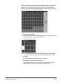
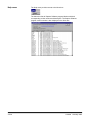
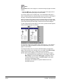
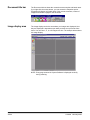
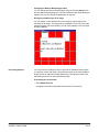
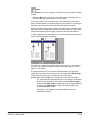
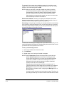
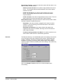
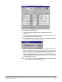
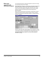
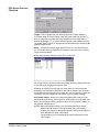
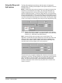
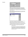
After a batch has been processed, Capture Software displays all rear images
below the specified number of bytes (e.g., 5000 bytes). These images are
displayed in a red highlight color (unless you disabled the Pre-select all
option). All colored images (which appear black here, but red on your screen)
are considered blank and ready for mass deletion.
To delete the blank images:
1. By default, all images are selected for deletion. Select any images you do
not want to delete by clicking them individually.
The color changes to white.
NOTE: The First Screen, Previous Screen, Next Screen, and Last Screen
buttons help you navigate through all the blank images in the batch.
2. Click OK.
The message Remove all selected images? appears.
3. Select Yes to confirm the deletion of images.
Capture Software removes the images and repaginates the documents.
The available batch and hard disk capacity are also updated.
A-63054 February 2004
3A-11
Changing the Remove Blank Images setup
You can change the Remove Blank Images setup by selecting Setup on the
Remove Blank Images dialog box. The Remove Blank Image Setup dialog box
appears and you can change the parameters as required.
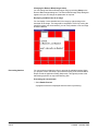
Displaying a detailed view of an image
You can display a more detailed view of an image by right-clicking on the
thumbnail of the image. The image will be magnified to 100%. By moving the
magnifying glass over the thumbnail, you can verify whether or not the image
should be deleted.
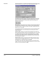
Processing batches
You can process one batch at a time or process all available batches. When
you process a batch, the batch is processed according to the selected Batch
Output Format in Application Setup (Output tab). This typically results in the
batch being copied to an output subdirectory path.
Processing the current batch
• Select Batch>Process.
A progress meter will be displayed while the batch is processing.
3A-12
A-63054 February 2004
Processing all available batches
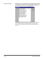
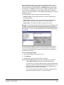
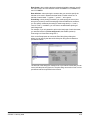
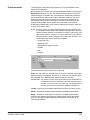
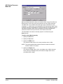
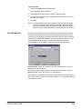
1. Select Batch>Process All.
The Process All Batches dialog box appears. This dialog box allows you to
select one or more batches to be processed.
2. Click Process.
Each selected batch is processed in the order displayed.
3. After processing, the Create New Batch dialog box appears.
By default, the name of the new batch is incremented by one. It is
suggested that you increment the previous batch name by one.
4. Click OK to continue scanning into the new batch.
Clearing and deleting batches
The Clear and Delete options are available from the Batch menu. When you
clear a batch, Capture Software deletes all images but keeps the batch
subdirectory name and all subdirectories that have already been created.
When you delete a batch, Capture Software deletes the entire batch
subdirectory structure and removes the batch name from the list of batches
in the selected application.
A-63054 February 2004
3A-13
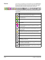
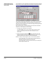
View menu
The View menu provides options which allow you to alter the way you view
images in the Image Display area.
1 Image—allows you to display one image in the Image Display area.
Keyboard shortcut: 1
2 Images—allows you to display two images in the Image Display area.
Keyboard shortcut: 2
4 Images—allows you to display four images in the Image Display area.
Keyboard shortcut: 4
8 Images—allows you to display eight images in the Image Display area.
Keyboard shortcut: 8
Scale to Gray—toggles the scale to gray mode on and off. Selecting Scale
to Gray will increase the quality of the bitonal images displayed on lower
resolution monitors. This option has no effect on the image files
Fit Images to Window—fits each image to the Image Display window
regardless of its original size. Keyboard shortcut: F
Zoom In—enlarges an image by a fixed percentage according to the Zoom
Step setting. Keyboard shortcut: +
Zoom Out—reduces an image by a fixed percentage according to the Zoom
Step setting. Keyboard shortcut: Zoom Step—accesses the Zoom Step dialog box which allows you to select a
percentage to scale. Options range from 15 to 40% in increments of 5%.
3A-14
A-63054 February 2004
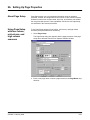
Changing zoom settings
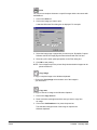
To change the settings in the Zoom Step dialog box, proceed as follows.
1. Select View>Zoom Step.
The Zoom Step dialog box appears.
2. Click on the setting you desire.
3. Click OK.
The zoom setting will be reduced or enlarged based upon the percentage
you selected.
A-63054 February 2004
3A-15
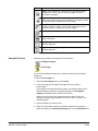
Document menu
Following is a summary of what options are provided from the
Document menu.
New—allows you to start a new document with a document number equal to
the last document number + 1. Keyboard shortcut: Enter
In Capture Software for 3000/4000 Series Scanners and Capture Software for
i800 Series Scanners, selecting this option also enables the scanner and starts
the scanner transport/feeder.
Attach—appends the next scanned page to the current document. Keyboard
shortcut: F4
Delete—deletes the current document. Keyboard shortcut: F8
Delete Range—accesses the Delete Documents dialog box which allows you
to delete a range of documents in the batch.
CDVue—this option is only available when you use the IBS/ Document CD
Native Scan structure. When this option is available, you can search and view
documents in the current batch with the CDVue application. This is useful for
testing the Document Index data that has been generated for the batch.
Keyboard shortcut: V
First—select this option to go to the first document in a batch. Keyboard
shortcut: Ctrl+Home
Last—select this option to go to the last document in a batch. Keyboard
shortcut: Ctrl+End
Previous—moves to the previous document number containing images.
Keyboard shortcut: Ctrl+Page Up
Next—moves to the next document number containing images. Keyboard
shortcut: Ctrl+Page Down
3A-16
A-63054 February 2004
Go to Document—accesses the Go to Document dialog box which allows you
to enter the number of the document that you want to display. You can also go
to document numbers that do not contain any images. Keyboard shortcut: D
First Image—allows you to go to the first image of a document. Keyboard
shortcut: Home
Last Image—allows you to go to the last image of a document. Keyboard
shortcut: End
Previous Screen—allows you to go to the previous screen. Keyboard
shortcut: Page Up
Next Screen—allows you to go to the next screen. Keyboard shortcut:
Page Down
Go to Image—accesses the Go to Image dialog box which allows you to enter
the number of the image you want to display first in the Image Display area.
Keyboard shortcut: I
Scroll Images to Top—allows you to scroll all of the images in the Image
Display area to the top of the images. Keyboard shortcut: Ctrl+Up Arrow
Scroll Images to Left—allows you to scroll all of the images in the Image
Display area to the left of the images. Keyboard shortcut: Ctrl+Left Arrow
Scroll Images to Bottom—allows you to scroll all of the images in the
Image Display area to the bottom of the images. Keyboard shortcut:
Ctrl+Down Arrow
Scroll Images to Right—allows you to scroll all of the images in the Image
Display area to the right of the images. Keyboard shortcut: Ctrl+Right Arrow
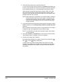
Deleting a range of pages
1. Select Document>Delete Range.
The Delete Documents dialog box appears.
2. Enter the beginning number of the document you want to delete in the
Delete all documents from field.
3. Enter the ending number of the group of documents you want to delete in
the up to field.
4. Click OK when finished.
A-63054 February 2004
3A-17
Moving to a specific
document or image
The Go to Document and Go to Images options are available when you want
to move directly to a specific document or image.
To go to a specific document:
1. Select Document>Go to Document.
The Go to Document dialog box appears.
2. Enter the document number you want to go to.
3. Click OK.
To go to a specific image:
1. Select Document>Go to Image.
The Go to Image dialog box appears.
2. Enter the image number you want to go to.
3. Click OK.
3A-18
A-63054 February 2004
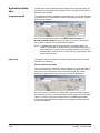
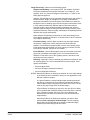
Index menu
The Index menu provides access to the index fields at batch, document, and
page levels. Following is a summary of each option.
Edit Batch Fields—when selected, the Batch Index Fields dialog
box appears.
Edit Document Fields—when selected, the Document Index Fields dialog
box appears.
Edit Page Fields—when selected, the Page Index Fields dialog box appears.
This function is not yet available, as page level index fields are not available.
To enter or change a batch or document index field:
1. Choose Edit Batch Fields or Edit Document Fields, depending upon
which fields you would like to edit.
The appropriate dialog box appears, containing an entry and value, if one
exists, for each index field defined during Application setup. In addition, the
first page of the batch (for batch index fields) or document (for document
index fields) is displayed next to the index field entries.
2. Change any information in the fields as required.
As you tab from field to field, the audit rules for the field are displayed (e.g.,
A(4) to enter up to four alphabetic characters).
3. Click OK to finish editing the current document/batch index fields.
The Image Display area of the Capture Software main window appears.
NOTE: Select Cancel to ignore any changes that were made. The Image
Display area of the Capture Software main window appears.
A-63054 February 2004
3A-19
For document index fields, two additional options are available:
• Select Next Doc to edit the index fields for the next document in a batch.
This option is useful for manual data entry indexing after scanning has
been completed.
• Select Next Invalid to go to the next document (or next field in the current
document) that has an invalid field value. This option is useful for index
correction after scanning has been completed.
NOTE: The last button used (Next Doc or Next Invalid) remains active,
allowing you to perform post-scanning indexing functions quickly using
the Enter key without using the mouse.
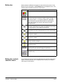
Image Display options
When editing index fields, several image display options are available. Image
display options are accessible from the Image Display Tool bar and an Image
Display context-sensitive menu.
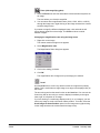
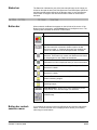
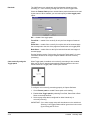
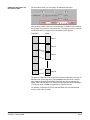
Image Display Tool bar
From left to right:
• The rotation buttons rotate the displayed image 90o, 180o, or 270o
clockwise. These buttons are useful to orient the image in the direction of
the index data (e.g., bar code data) that needs to be entered/corrected.
IMPORTANT: When an image is rotated and the index field changes are
saved (i.e., not canceled), any rotation of the image is
also saved.
• The Zoom image with magnifying glass tool is the same as the tool on the
Capture Software main window.
• The Zoom image on rectangle tool allows you to draw a rectangle around
a portion of the image that you want zoomed for display when editing index
fields. This zoom setting is saved per index field. As a result, you can define
a zoom zone for each index field and the image display automatically zooms
to the appropriate part of the image when that field is edited.
• The Scroll image tool is the same as the tool on the Capture Software main
window. The results of scrolling are saved per index field.
• The Front and Rear radio buttons control which side of a duplex page is
displayed when editing index fields. The front/rear setting is saved per index
field. As a result, when tabbing between index fields, the image display can
automatically switch from front to rear and back again.
3A-20
A-63054 February 2004
Image Display context-sensitive menu
These menu options function the same as they do on the Capture Software
main window image context-sensitive menu. Any adjustments to image display
by zooming in/out or fit image to window are saved per index field.
NOTES: All adjustments to image display from the tool bar or the contextsensitive menu are automatically saved, per Capture Software
application, when leaving the Batch/Document Index Fields dialog
box. As a result, the next time fields are edited, the image display
settings used previously remain in effect.
The Batch and Document Index Fields dialog boxes can be resized
and moved to a different position on the screen. When leaving the
dialog box, the size and on-screen positions are automatically saved.
As a result, the next time index fields are edited, the location and size
of the dialog box used previously remain in effect.
Index correction during scanning
When index fields are defined with the Check Field During Scanning option
enabled, each index field value is audited against the input mask and minimum
length requirements for the field. If an index field audit fails, scanning will be
interrupted and you will be prompted to correct the index data before scanning
can be resumed.
If the Stop Scanner on Error option is enabled for the application, the
scanner must be manually restarted (green button on the Scanner bar) to
resume scanning. Otherwise, scanning will automatically resume when the
index field is corrected.
A-63054 February 2004
3A-21
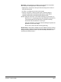
Tools menu
Following is a brief summary of each option on the Tools menu. The Tool bar
also provides most of these options. See the section entitled “Tool bar” in this
chapter for an explanation of the Tool bar buttons.
Re-Append Images—this option is available only when the Insert Image tool
is used. Use this option after Insert is completed to reattach the ending images
of a document with the inserted images.
Insert Image—allows you to insert additional pages into a scanned document.
Keyboard shortcut: Insert
Rescan Image—allows you to rescan a selected image. Keyboard shortcut: R
Delete Image—allows you to delete one or more images selected inside a
document. For example, blank images can be deleted from a double-sided
document; Capture Software will renumber all remaining images after the
selected images are deleted. Keyboard shortcut: Delete
Delete End of Document—allows you to delete the selected image and all
subsequent images of a document. Images are removed from your hard
disk. You cannot undo this function.
Confirm Image—allows you to confirm unchangeable actions (no undo).
Actions you cannot undo, and therefore must confirm, are: deleting and
cropping images, blanking parts of one or more images, and copying parts of
an image to the Windows clipboard. Keyboard shortcut: Space
Flag Image—allows you to indicate that something special needs to be done
with a particular image. This function is not yet available.
3A-22
A-63054 February 2004
Rotate 90°—allows you to rotate an image 90 degrees to the right. Keyboard
shortcut: Shift+Right Arrow
Rotate 180°—allows you to rotate an image 180 degrees. Keyboard shortcut:
Shift+Up or Down Arrow
Rotate 270°—allows you to rotate an image 270 degrees to the right (or 90
degrees to the left). Keyboard shortcut: Shift+Left Arrow
Zoom—allows you to enlarge a portion of an image. When you select Zoom, a
magnifying glass will be displayed. You can enlarge any area where you place
the magnifying glass. You can also select other magnification ratios (100, 150,
200, or 250%) by right-clicking on the image and selecting Magnification
Ratio from the context-sensitive menu. The Magnify tool does not slide
between images. Keyboard shortcut: Z
Scroll—use the Scroll option to scroll in any direction within an image that is
partially hidden. This is useful when a single image is too large to be displayed
fully on the screen. Keyboard shortcut: S
Blank—use the Blank tool to select an area of an image that you want to
remove from the image. Keyboard shortcut: Ctrl+X
Crop—allows you to draw a rectangle around a portion of an image retaining
only the part of the image you want.
Move—allows you to move a page (both front and rear images) from one
location to another location within the document. To move an image, right-click
on the image and select Move image on the context-sensitive menu to change
the move tool setting. Keyboard shortcut: M
Split—allows you to split a document into two documents.
Print—allows you to print a document or specific images within a document.
Only black-and-white images can be printed at this time. Keyboard shortcut:
Ctrl+P
Copy—allows you to copy an image (in its highest resolution) to the Windows
clipboard. Keyboard shortcut: Ctrl+C
Copy Area—allows you to copy a specific area of an image to the
Windows clipboard.
A-63054 February 2004
3A-23
Scanner menu
The Scanner menu provides the following functions:
Setup—accesses the Setup dialog box specific to the scanner you selected.
From this dialog box you can set the SCSI parameters and other specific
parameters for the selected scanner.
Stop—clears and stops the transport and disables the scanner. Keyboard
shortcut: F6
Start—enables the scanner and starts the transport. Keyboard shortcut: F7
Image Calibration—allows you to calibrate the scanner. You may need to
calibrate the scanner if you are experiencing problems with image quality.
NOTE: This function is only available in Capture Software for the Scanner
3500, Scanner 3510, Scanner 3520, Color Scanner 3590C, Color
Scanner 4500, and all i800 Series Scanners.
Color Calibration—allows you to calibrate the Color Scanner 3590C or Color
Scanner 4500 for color image quality.
NOTE: This function is only available in Capture Software for the Color
Scanner 3590C or Color Scanner 4500.
Multi-feed Thickness Calibration—allows you to calibrate the scanner for
multi-feed document detection based on the thickness of a scanned sheet of
paper. When prompted, feed a sample sheet into the scanner. When Multifeed Thickness Detection is actuated after calibration, the scanner warns you
with an audible alarm whenever a scanned sheet of paper is detected to be
thicker (commonly caused by a multi-feed) than the sheet used for calibration.
See Chapter 9, Page Setup, for information about actuating Multi-feed
Thickness Detection.
NOTE: This function is only available in Capture Software for the Scanner
3500, Scanner 3510, Scanner 3520, Color Scanner 3590C, or Color
Scanner 4500.
Set Counter—accesses the Set Counter dialog box which allows you to
change the sequential counter value assigned (and optionally printed) to the
next page scanned. On the Scanner 1500 and Scanner 2500, the counter
value that is entered will appear on the LCD display.
NOTE: This function is only available in Capture Software for the Scanner
1500, Scanner 2500, Scanner 3520DP, Color Scanner 4500DP, and all
i800 Series Scanners.
3A-24
A-63054 February 2004
Additional menu options
for high volume scanners
For high volume scanners, such as Scanner 5500, Scanner 7520,
Scanner 9520, or the i800 Series Scanners, two additional menu options
can be selected.
Set Mode—accesses the Set Mode dialog box which allows you to change the
scanning mode on the high volume scanner. If the mode selected is a linked
mode to the current mode (as defined by the scanner), then the image address
will not change. However, if the mode selected is not linked to the current
scanner, then the image address will change to the last address used for
the mode.
NOTES: It is recommended that you always change the mode within Capture
Software, as opposed to changing the mode at the scanner keypad
(i.e., using the F01 function). If you change the mode at the scanner
keypad, you may not be able to restart the scanner in Capture
Software due to a mismatch in the expected Image Address format
between the scanner and Capture Software.,
Set Mode is not available for the i800 Series Scanners which only
support one operative mode configurable in Application Setup.
Set Image Address—accesses the Set Image Address dialog box which
allows you to change the image address that is displayed on the high volume
scanner (and optionally printed). Only those image address fields (e.g., Fixed
field, Level 2) that are applicable to the scanner mode being used can be
modified. By default, Capture Software suggests an image address based
upon the Application Setup that resynchronizes the current Capture Software
document number with the scanner image address.
A-63054 February 2004
3A-25
Setting up the scanner
You can set up or change the parameters of the scanner you will be using by
accessing the Setup dialog box.
1. Select Scanner>Setup.
The Scanner Setup dialog box appears.
2. Enter a Transport Time-out value, if desired.
Valid values for the time-out period depend upon the attached scanner.
For the Scanner 3500, Scanner 3510, Scanner 3520, Color Scanner
3590C, and Color Scanner 4500, valid values are 3 to 30 seconds.
The Transport Time-out is the number of seconds that the scanner
transport remains enabled when not actively scanning. When a time-out
occurs, the scanner transport stops and is disabled.
3. Enable or disable the Lamp saver setting.
A check in the box indicates that Lamp saver is enabled; no check
indicates that it is disabled. In order for a change in the setting to take
effect, you must scan at least one page. When Lamp saver is enabled,
the lamps in the scanner automatically shut off after 10 minutes of scanner
inactivity. When this feature is disabled, the lamps in the scanner remain
on until the scanner is powered off.
NOTE: Transport Timeout and Lamp saver are only available in Capture
Software for the Scanner 3500, Scanner 3510, Scanner 3520, Color
Scanner 3590C, and Color Scanner 4500.
3A-26
A-63054 February 2004
Upon startup, Capture Software automatically locates the scanner and fills
in the adapter number and SCSI ID of the scanner. If the scanner was not
ready or powered up when Capture Software was started, press the Find
SCSI Address button to locate the scanner and fill in the fields if the
scanner is available. To key in the adapter number or SCSI ID manually,
the following applies:
• If the scanning PC contains more than one SCSI adapter, enter the
appropriate adapter number in the Adapter number field, otherwise, leave
the adapter number to its default value of 0.
• Enter the SCSI ID number of the attached scanner, usually a number from
1 to 7.
For the Scanner 1500 and Scanner 2500, the SCSI ID number is visible in
the LCD display on the front of the scanner. Press the down arrow on the
display panel until the SCSI ID appears in the LCD display.
For the Scanner 3500, Scanner 3510, Scanner 3520, Color Scanner 3590C,
and Color Scanner 4500, the SCSI ID number is visible in the small box on
the back panel of the scanner.
The Emulation mode check box is used to enable/disable running
Capture Software in emulation mode without an attached scanner. For
more information on the Emulation mode check box, refer to Appendix A,
Installation.
NOTE: If the SCSI Address or Emulation mode settings are changed, you may
need to exit and restart Capture Software in order to scan successfully.
4. Press the About button to display information about the attached scanner.
A-63054 February 2004
3A-27
Additional settings for
high volume scanners
For the Scanner 5500, Scanner 7520, and Scanner 9520, the Scanner Setup
dialog box has the additional settings shown below.
True Simplex—allows you to operate a duplex Kodak high volume scanner
more efficiently when scanning single-sided documents in simplex mode. By
default, this setting is disabled. You should use it only when scanning small
documents (e.g., postcard-size documents) in simplex mode.
Kodak high volume scanners have 18 scanning modes that can be set up for
different scanning applications (imprinting, image address format, level rules,
document separator, hardware bar code/patch code reading, etc.).
In Capture Software, you must define the image address format (i.e., lengths
of the image address fields) for each mode to be used for scanning. The image
address format as defined in Capture Software must be identical to the format
as defined in the scanner.
3A-28
A-63054 February 2004
Mode Setup
The default image address format for each mode in Capture Software matches
the factory setting of the mode defined in the scanner. As a result, you should
only need to make changes in Capture Software if mode changes were made
in your scanner through the KODAK Scanner Mode Setup Software.
To make changes to your mode setting in Capture Software, do the following:
1. Select a Mode from the drop-down list of 18 mode numbers.
2. Enter an optional mode Name that will be displayed in Capture Software
whenever you are selecting a mode to be downloaded to the scanner.
3. Enter the Image address length for each of the image address fields.
The lengths of the image address fields must match the image address
format as defined in the scanner. To assist you in determining what the
lengths should be, click on the Read from scanner button. This will adjust,
if necessary, the image address lengths to match the lengths as defined in
the scanner.
NOTES: The total of all of the image address lengths must not exceed
12 characters.
A length of “0” means that the image address field is not used or it is
not applicable for the selected mode.
Read from scanner is operational only for the Scanner 5500 and
Scanner 7500/7520.
A-63054 February 2004
3A-29
Additional settings for
the Scanner 1500 and
Scanner 2500
For the Scanner 1500 and Scanner 2500, the Scanner Setup dialog box has
the additional settings shown below.
The Scanner 1500 and Scanner 2500 paper feed rollers and separator rollers
must be cleaned and replaced periodically.
Clean roller status—allows you to clear the Clean Roller warning when it
occurs on the scanner. Clean the rollers, then press the Reset button to clear
the warning.
Replace roller status—allows you to clear the Replace Roller warning when it
occurs on the scanner. Replace the rollers, then press the Reset button to
clear the warning.
See the multimedia User’s Guide for the Scanner 1500 or the Scanner 2500
for information about cleaning and replacing the rollers.
3A-30
A-63054 February 2004
Specific settings for the
i800 Series Scanners
For the i800 Series Scanners, the Scanner Setup dialog box has the specific
settings shown below.
Auto-start transport—allows you to start the scanner transport and feeder
automatically when the Start Scanner button is pressed in the main window of
Capture Software. By default, this setting is enabled. When disabled, the
scanner transport will not automatically start. As a result, you must press the
green button on the scanner operator control panel to initiate scanner feeding.
The following settings will only take effect when at least one page is scanned.
Lamp time-out—when enabled, the lamps in the scanner will automatically
shut off after a specified number of minutes of scanner inactivity. Valid values
are 1 to 30 minutes. When this feature is disabled, the lamps in the scanner
remain on until the scanner is powered off.
Transport time-out—when enabled, the scanner transport and feeder will
automatically stop after a specified number of seconds of no scanning.
Valid values are 5 to 300 seconds. When this feature is disabled, the
scanner transport and feeder remain on until the scanner is disabled in
Capture Software.
A-63054 February 2004
3A-31
Transport time-out action—select an option to determine what takes place
when the transport times out.
• Select End job to stop the transport and feeder and disable the scanner.
Scanning must be reinitiated from Capture Software.
• Select Stop feeder and transport to stop the transport and feeder, and
leave the scanner enabled. Scanning can be reinitiated by pressing the
green button on the scanner operator control panel.
Function keys 1-3—the i800 Series Scanners have three programmable keys
that are accessible from the operator control panel. These keys are available
for use by the operator when the scanner is enabled. The operator control
panel displays the numbers 1 through 3 corresponding to the buttons on the
control panel that represent the function keys.
Each of the programmable keys can be assigned to the following functions:
• Select None for no scanner functionality. This is the default setting.
• Select End Job to stop the feeder and transport and disable the scanner.
Scanning is stopped in Capture Software.
• Select Terminate Batch to terminate the active batch when scanner
batching is enabled. See the i800 Series Scanner options in Chapter 4,
Application Setup.
• Select Skip multi-feed detection on next document to turn off multifeed
detection for the next page scanned.
• Select Skip printing on next document to turn off printing for the next
page scanned.
• Select Skip patch reading on next document to turn off patch code
reading for the next page scanned.
3A-32
A-63054 February 2004
Page menu
The following Page menu options are available. Most of these options can also
be selected by using the Scanner bar.
Setup List—accesses a drop-down list of all Page Setup names that have
been defined. Allows you to select a page setup to use for the application.
Once selected from the Setup List, Capture Software automatically downloads
the page properties and starts the scanner. Keyboard shortcut: F2
Setup—displays the Page Setup dialog box which enables you to set up the
properties of the pages to be scanned. For more information about Page
Setup, refer to Chapter 9, Setting up Page Properties. Keyboard shortcut: F5
Front—select this option to enable/disable simplex, front only scanning.
Keyboard shortcut: F9
Rear—select this option to enable/disable simplex, rear only scanning.
Keyboard shortcut: F10
Duplex—select this option to scan double-sided pages with a duplex scanner.
Keyboard shortcut: F11
Classic—duplex mode typically associated with multi-page documents; such
as, reports, postcards, articles. See the section entitled “About Duplex modes”
for more information. Keyboard shortcut: F12
Calendar—duplex mode typically associated with documents such as
presentation handouts, statistical and financial reports, project planning
reports. See the section entitled “About Duplex modes” for more information.
Keyboard shortcut: F12
A-63054 February 2004
3A-33
Specific settings for the
i820 Scanner and
i840 Scanner
For the i820 Scanner and i840 Scanner, which can scan in both color and
black and white simultaneously, the Page menu has the specific settings
shown below.
Bi-tonal—both front and rear bitonal are enabled. Select this option to enable
bitonal-only scanning. Keyboard shortcut: F9
Color—both front and rear color are enabled. Select this option to enable
color-only scanning. Keyboard shortcut: F10
Dual Stream—select this option to enable dual-stream scanning (both front
and rear color and bitonal). Keyboard shortcut: F11
3A-34
A-63054 February 2004
About Duplex modes
The way a document is printed influences the orientation of the images
produced by the scanner. There are two different ways of printing
duplex documents.
Classic duplex format is typically associated with multi-page reports.
Reports, postcards, articles, etc. are all printed according to the classic
duplex format.
Calendar duplex format is more unusual. It is used for presentation
handouts, statistical and financial reports, project planning reports, etc.
The following illustrates typical duplex classic and calendar formats:
Classic duplex format
Calendar duplex format
The Duplex buttons (on the Tool bar)
To use these buttons, look at your original and compare it with the picture on
the duplex buttons. Click on the button that corresponds with your original.
The duplex mode only influences the way the front image will be rotated in
relation with the rear image. It does not set the overall rotation of the document
(0°, 90°, 180°, or 270°). Rotation can be set up in the Page Setup dialog box.
The first button handles classic duplex formats:
• A 0° rotated front corresponds with a 0° rotated rear.
• A 180° rotated front corresponds with a 180° rotated rear.
• A 90° rotated front corresponds with a 270° rotated rear.
• A 270° rotated front corresponds with a 90° rotated rear.
The second button handles all calendar duplex formats:
• A 0° rotated front corresponds with a 180° rotated rear.
• A 180° rotated front corresponds with a 0° rotated rear.
• A 90° rotated front corresponds with a 90° rotated rear.
• A 270° rotated front corresponds with a 270° rotated rear.
If you have images in the current document and you toggle the duplex mode
buttons, the message Do you want to apply the selected duplex mode to the
already scanned images in the current document? appears.
If you select Yes, Capture Software will rotate the images in the current
document according to the selected duplex mode.
NOTE: When color scanning with the Color Scanner 3590C,
Color Scanner 4500, i820 Scanner, or i840 Scanner,
only classic duplex mode is supported.
A-63054 February 2004
3A-35
Selecting a page setup
Capture Software comes with several pre-defined page setups The list of predefined page setups will vary depending upon which Capture Software product
and Kodak scanner are being used. To access the Page Setup list from the
main Capture Software window, select Page>Setup List.
To select a page setup from the drop-down list either use the mouse, arrow
keys or enter the first letters of the page setup name. Capture Software
automatically scrolls down the Page Setup List until a unique page setup
is found.
3A-36
A-63054 February 2004
Options menu
The Options menu allows you to customize the Capture Software screen
layout and display or hide the Scanner bar, Tool bar, Button bar, or Status bar.
For more information about each of these bars, see the appropriate section
within this chapter.
Extended Scanner bar—in addition to the Default Scanner bar, the Extended
Scanner bar displays threshold and contrast settings. See the section entitled
“Scanner bar” later in this chapter. Keyboard shortcut: Ctrl+E
Default Scanner bar—the Default Scanner bar displays the Start and Stop
buttons, the Duplex buttons, the Page name information and the front and rear
scan options. Keyboard shortcut: Ctrl+D
Tool bar—the Tool bar provides shortcuts to commonly used image
manipulation commands in Capture Software. Clicking on one of these buttons
is equivalent to selecting the corresponding command from the menu bar. The
Tool bar is described in more detail in the section entitled “Tool bar” later in this
chapter. Keyboard shortcut: Ctrl+T
Button bar—the Button bar provides shortcuts to commonly used image
display and navigation commands in Capture Software. Clicking on one of
these buttons is equivalent to selecting the corresponding command from the
menu bar. The Button bar is described in more detail in the section entitled
“Button bar” later in this chapter. Keyboard shortcut: Ctrl+B
Status bar—the Status bar indicates the size of the last-scanned image or the
image you clicked on last. The Status bar is described in more detail in the
section entitled “Status bar” later in this chapter. Keyboard shortcut: Ctrl+S
A-63054 February 2004
3A-37
Help menu
The Help menu provides access to the About box.
The About box lists all Capture Software program libraries with their
corresponding version number and description. The Capture Software
program version number is also displayed in the About box.
3A-38
A-63054 February 2004
Scanner bar
Default Scanner bar
The Scanner bar provides tools for controlling the scanner from within Capture
Software. If the Scanner bar is not visible, open the Options menu and click on
the Scanner bar option. The Scanner bar displayed below is for a duplex
scanner scanning both sides of the page.
The Default Scanner bar provides the following options.
Button
Description
Stop—clears and stops the transport/feeder and
disables the scanner.
Start—enables the scanner and starts the transport/
feeder.
Classic—duplex scanning format typically associated
with multi-page reports. Reports, postcards, articles,
etc., are all printed according to the classic
duplex format.
Calendar—duplex scanning format typically used for
presentation handouts, statistical and financial reports,
project planning reports, etc.
NOTE: Calendar duplex mode is not supported when
color scanning with the Color Scanner 3590C,
Color Scanner 4500, i820 Scanner, or i840 Scanner.
Page—displays the current/active page setup. Use the
drop-down list button to select a different page setup.
Front—select this option to enable/disable simplex,
front only scanning.
Rear—select this option to enable/disable simplex,
rear only scanning.
Specific options for
the i820 Scanner and
i840 Scanner
For the i820 Scanner and i840 Scanner, which can scan in both color and
black and white simultaneously, the Default Scanner bar has the specific
settings shown below.
Button
Description
Bi-tonal—select the Front and Rear buttons to enable/
disable front and/or rear bitonal scanning.
Color—select the Front and Rear buttons to enable/
disable front and/or rear color scanning.
A-63054 February 2004
3A-39
Extended Scanner bar
The Extended Scanner bar has all of the options listed previously plus the
following options:
Button
Description
Threshold—controls the lightness and darkness of the
background in an image. Valid values are 0 to 255.
Contrast—contrast enhances the edges contained in a
document. The higher the contrast level, the more the image
edges will be enhanced. Valid values are 0 to 100.
NOTES: Changing the duplex scanning format, front and rear selection, and
threshold/contrast settings from the Scanner bar are temporary
settings for the current scanning session and do not affect the
currently selected page setup.
Threshold and Contrast are only applicable when scanning in black
and white. Therefore, they are not available when scanning in color
with the Color Scanner 4500. However, when MultiStream™ support
(i.e., where each color image is converted to a corresponding
bitonal image) is enabled in the currently selected page setup,
Threshold and Contrast remain enabled. When color images are
binarized, the Threshold and Contrast settings are used as part of
the binarization process.
Specific options for
the i820 Scanner
and i840 Scanner
For the i820 Scanner and i840 Scanner, which can scan in both color and
black and white simultaneously, the Extended Scanner bar has the specific
settings shown below. .
Button
Description
Threshold—controls the lightness and darkness of the
background in a bitonal image. Valid values are 0 to 255. Enter a
front side threshold value in the text box on the left. Enter a rear
side threshold value in the text box on the right.
Contrast—contrast enhances the edges contained in a
document. The higher the contrast level, the more the image
edges will be enhanced. Valid values are 0 to 100. Enter a front
side contrast value in the text box on the left. Enter a rear side
contrast value in the text box on the right.
Specific options for scanners
with the iThresholding feature
For the Scanner 3520 and i800 Series Scanners with the iThresholding
feature, the Extended Scanner bar has the specific settings shown below. .
Button
Description
iThresholding—activates the iThresholding feature.
When iThresholding is enabled, the Threshold ( ) entry box
is disabled.
3A-40
A-63054 February 2004
Scanner bar
context-sensitive menu
If you position the mouse cursor on the Scanner bar and click the right mouse
button, the context-sensitive menu will appear. The following menu options
are available.
Page Setup—accesses the Page Setup dialog box where you can set up page
properties for an application.
Default Bar/Extended Bar—allows you to toggle between the Extended
Scanner bar and the Default Scanner bar.
Large Buttons/Small Buttons—allows you to toggle between displaying
large and small buttons on the Scanner bar.
Image Calibration—allows you to calibrate the scanner.
NOTE: This option is available only in Capture Software for all mid-volume
3000/4000 Series Scanners and i800 Series Scanners.
Color Calibration—allows you to calibrate the Color Scanner 3590C or
Color Scanner 4500 for color image quality.
NOTE: This function is only available in Capture Software for the
Color Scanner 3590C and Color Scanner 4500.
Multi-feed Thickness Calibration—allows you to calibrate the scanner for
multi-feed detection.
NOTE: This function is only available in Capture Software for the Scanner
3510, Scanner 3520, Color Scanner 3590C, and Color Scanner 4500.
Set Counter—this option appears when the scanner has a document printer.
• For the Scanner 1500 or Scanner 2500: allows you to change the counter
value to be printed and/or displayed on the scanner’s LCD display.
• For the Scanner 3520DP and Color Scanner 4500DP: allows you to change
the counter value to be printed on the next scanned page when document
printing is enabled.
• For the i800 Series Scanners: allows you to change the counter value
assigned (and optionally printed) to the next scanned page.
Set Mode—allows you to change the scanning mode on the high volume
scanner. This option is available only for Capture Software for the 5000, 7000,
and 9000 Series Scanners.
Set Image Address—allows you to change the image address that is
displayed on the high volume scanner (and optionally imprinted). By default,
Capture Software suggests an image address based upon the Application
Setup that resynchronizes the current Capture Software document number
with the scanner image address. This option is available only for all Kodak high
volume scanners (5000, 7000, 9000, and i800 Series Scanners).
A-63054 February 2004
3A-41
Tool bar
If the Tool bar is not displayed, it can be displayed by choosing Options>Tool
bar. The following table describes the function of each button on the Tool bar.
Procedures on how to use these functions are also included in this section.
Most of these options can also be accessed from the Tools menu.
The following list provides all of the Tool bar options and a brief summary of
their functions.
Button
Description
Re-Append images—allows you to re-append the remaining
images of a document after an Insert operation.
Insert image—allows you to insert additional images into a
scanned document.
Rescan—allows you to rescan images in a document.
Delete image—click this button if you want to delete one or
more images.
Delete end of document—click this button to delete the selected
image and all subsequent images of a document. This action
cannot be undone.
Confirmation—allows you to confirm an unchangeable action (no
undo). Confirmation is required for the Delete, Blank, Crop, and
Copy Area tools.
Flag image—use this tool to indicate something special has to be
done with an image after batch processing. Not yet available.
Rotate 90°—rotates the selected image 90 degrees to the right.
Rotate 180°—rotates the selected image 180 degrees.
Rotate 270°—rotates the selected image 270 degrees to the right
(i.e., 90 degrees to the left).
Zoom—allows you to enlarge a portion of an image. When you
select Zoom, a magnifying glass will be displayed. The Zoom tool
does not slide between images.
Scroll—allows you to scroll in any direction within an image that is
partially hidden. This is useful when a single image is too large to
be displayed fully on the screen.
3A-42
A-63054 February 2004
Button
Description
Blank—you can blank out a specific part of an image by using
the Blank tool. This is useful to clean up images or remove
confidential information.
Crop—allows you to draw a rectangle around a specific area of an
image and discard any information outside the rectangle. Use this
tool to keep only the significant part of an image.
Move—use the Move tool to move a page or a consecutive range
of pages to another location. You can also set the Move tool to
move an image or a consecutive range of images.
Split—allows you to split a document into two documents.
Print—allows you to print a complete document, or specific images
within a document.
Copy image—allows you to copy a complete image to the
Windows clipboard.
Copy area—allows you to copy an area of an image to the
Windows clipboard.
Using the Tool bar
Following are procedures for using the Tool bar options.
Re-Append images
Insert image
You can insert additional images into a scanned document with the Insert
image tool.
To use the Insert image tool:
1. Select the Insert image tool (or press Insert).
2. Click on the page (front image of the page) where you want to
insert images.
The images will be inserted before this page. The selected page and all
following images are placed in a temporary buffer. The Re-Append
images tool appears at the left side of the Tool bar.
When you click on the rear of a page that also contains a front, the
message Inserting images between a front and a rear of a page is not
allowed appears.
3. Scan the images you want to insert.
4. When you have finished scanning, recall the images in the temporary
buffer by clicking on the Re-Append images tool or the Confirmation tool.
A-63054 February 2004
3A-43
Rescan
To rescan images in a document:
1. Select the Rescan tool (or press R).
2. Click on the images to be rescanned. To select multiple images, use the
CTRL-click and SHIFT-click Windows techniques.
If only the front or rear scanner is enabled, scanned images will replace all
selected images until no selected images are available. Subsequent
scanned images will be appended to the document. When a front image
replaces a rear image, the new scanned image will also be marked as a
rear and vice versa.
When you use the scanner in duplex mode re-scan is done on a page-perpage basis. Capture Software analyzes each selected page and replaces
fronts by fronts and rears by rears. When the selection does not include
certain rears or fronts, Capture Software discards the corresponding
scanned images. Once all selected images are replaced, subsequent
scanned pages will be appended to the document.
Rescanning binarized color pages
When using the Rescan tool on color pages that have been binarized
(i.e., converted to black and white for MultiStream™ processing), the following
guidelines must be followed to ensure a successful rescan operation. These
guidelines are important because when a scanned color page is binarized, the
page can contain up to four images (front bitonal, rear bitonal, front color, and
rear color).
• If only color images need to be rescanned, select a page setup that has
binarization disabled (e.g., the Color 150 DPI – Deskew – Keep All Images
page setup that is provided with Capture Software).
• If only binarized images need to be rescanned, (e.g., to adjust the Contrast
or Threshold), select a page setup where only the bitonal images are kept
(e.g., the Color 150 DPI – Deskew – Binary Only for Rescan page setup that
is provided with Capture Software).
• If both color and bitonal images need to be rescanned, highlight both a
bitonal and a color image for rescan. Select a page setup where binarization
has been enabled (e.g., the Color 150 DPI – Deskew – Dual Stream page
setup that is provided with Capture Software).
• When rescanning binarized color pages on the Color Scanner 3590C,
highlight all three images of the page and select a page setup where
binarization had been enabled (e.g., Color 150 DPI – Deskew –
Dual Stream).
3A-44
A-63054 February 2004
Rescanning when using dual stream with an i800 Series Scanner
When scanning dual stream (both front and rear color and bitonal) with an i820
Scanner or i840 scanner, the following guidelines must be followed to ensure a
successful rescan operation:
• After highlighting the images of the page that you want rescanned, go to the
Scanner bar and use the Front/Rear buttons to enable only those images
that are highlighted for rescan.
For example, if only the Front bitonal and Front color images need to be
rescanned, then the Scanner bar would look like the example below when
the scanner is restarted.
Similarly, if only the Front and Rear bitonal images need to be rescanned,
then the Scanner bar would look like the example below when the scanner
is restarted.
IMPORTANT: Not following these color rescanning guidelines may result
in additional images being appended to the end of the
current document.
A-63054 February 2004
3A-45
Delete image
You can delete one or more images selected inside a document using the
Delete image tool. For example, use this tool for the deletion of blank images
from a double-sided document. Capture Software renumbers all remaining
images after the selected images are deleted.
1. Click on the Delete image tool (or press Delete).
2. Click on the images you want to delete. To select multiple images, use the
CTRL-click and SHIFT-click Windows techniques.
3. Click the Confirmation tool (or press the space bar) to confirm deletion of
the selected pages.
IMPORTANT: Once confirmed, the selected pages are removed from your
system’s hard disk. You cannot undo this action.
Delete end of document
1. Click on the Delete end of document tool.
The message Using this tool may lose a lot of images. Continue
anyway? appears.
2. Click Yes to continue.
3. Click on any image to delete that image, and all subsequent images.
IMPORTANT: The images are removed from your system’s hard disk. You
cannot undo this action.
Confirmation
Use the Confirmation tool (or press the space bar) to confirm the following
unchangeable actions (no undo):
• deleting images
• cropping images
• blanking parts of one or more images
• copying parts of an image to the Windows clipboard
The Confirmation tool also
• appends images from the insert buffer
• deselects all the images selected for rescan
3A-46
A-63054 February 2004
Flag image
You can indicate that something special has to be done with certain images by
using the Flag image tool. For example, flagged images can be used to
indicate that an image has to be processed by an OCR system for data
extraction. This function is not yet available.
1. Select the Flag image tool.
2. Click on the image you want to flag.
Flagged images will be colored yellow. If you want to flag multiple images
on the screen, use the CTRL-click and SHIFT-click Windows techniques.
Rotate
The Rotate tools rotate images 90° right, 180°, or 90° left (270° right). This tool
physically rotates the image file, so that when viewed later in any application, it
has the same orientation as displayed in Capture Software.
1. Select the desired Rotate tool.
2. Click on the image you want to rotate. If you want to rotate all images on
the screen or undo the action, select the appropriate function from the
Image menu (right-clicking on the image accesses the context-sensitive
Image menu).
NOTE: When rotating color images, the default operation is a pixel-precise
color image rotation. If continuously repeated on the same color
image, pixel-precise rotation may result in some loss of color image
quality. To avoid any image quality loss when rotating a color image,
select Enable Fast Color Processing from the Image menu (rightclicking on the image accesses the context-sensitive Image menu).
Fast image rotation may, however, result in the addition of a small
amount of black border along some image edges. To re-establish pixelprecise rotation, select Enable Pixel Precision from the Image menu.
A-63054 February 2004
3A-47
Zoom (with magnifying glass)
1. Select the Zoom tool and click and hold the left mouse button anywhere on
an image.
The zone where you clicked is magnified.
2. You can select other magnification ratios (100%, 150%, 200%, or 250%)
through the Image menu (right-clicking on the image accesses the contextsensitive Image menu).
If you want to magnify a different displayed image, click and hold the left
mouse button anywhere on that image. The Zoom tool does not slide
between images.
Changing the magnification ratio using the Image menu
1. Right-click on the image.
The context-sensitive Image menu appears.
2. Select Magnification ratio.
The Magnification Ratio dialog box appears.
3. Click on the setting you desire.
4. Click OK.
The magnification ratio changes to the percentage you selected.
Scroll
Use the Scroll tool to scroll in any direction within an image that is partially
hidden. This is useful when a single image is too large to be displayed fully on
the screen.
The arrow keys perform the same function as the Scroll tool. You can use the
Control key with an arrow key to move the display immediately to the upper,
lower, right, or left portion of an image.
If you are working in a multi-image display mode (2, 4, or 8 images), you can
latch every image to scroll to the same relative position. To do this, select the
Scroll Images to Same Position option from the Image menu (right-clicking
on the image accesses the context-sensitive Image menu).
3A-48
A-63054 February 2004
Blank
With the Blank tool you can blank out a specific part of an image. Use this
tool to clean up images or to remove confidential information (i.e., to protect
a name).
To blank part of an image:
1. Select the Blank tool.
2. Point to the upper left corner of the area you want to blank out.
3. Click and drag the mouse diagonally over the area you want to blank out.
NOTE: If you want to blank out the same area on all images on the screen,
draw the rectangle on any of the images and duplicate the
rectangle by selecting Apply Blank Rectangle to Screen from the
Image menu (right-clicking on the image will display the contextsensitive Image menu).
4. Click on the Confirmation tool to confirm your actions.
Data within the rectangle is blanked out. You cannot undo this action.
You can also draw different rectangles on different images.
Crop
With the Crop tool, you can crop an image to a drawn rectangle. Use this tool
to keep only the significant part of an image (i.e., newspaper articles).
1. Select the Crop tool.
The mouse pointer now resembles scissors with an arrow.
2. Point to the upper left corner of the area you want to keep.
3. Click and drag the mouse diagonally over the area you want to keep.
4. Release the mouse button and a rectangle is displayed. If it is not
acceptable, you can redraw the rectangle (only one rectangle per image)
by repeating the above actions.
5. Click on the Confirmation tool. The image(s) are cropped to the area
within the rectangle(s). You cannot undo this action.
NOTES: If you want to crop the same area on all images on the screen,
use the appropriate option from the Image menu (right-clicking on
the image accesses the context-sensitive Image menu).
When cropping color images, the default operation is a pixelprecise image crop. If continuously repeated on the same image,
some loss of color image quality may occur. To avoid any image
quality loss when cropping a color image, select Enable Fast
Color Processing from the Image menu (right-clicking on the
image accesses the context-sensitive Image menu). Fast image
crop, however, is not as accurate as pixel-precise image crop.
To re-establish pixel-precise cropping, select Enable Pixel
Precision from the Image menu.
A-63054 February 2004
3A-49
Move
Use the Move tool to move a page or a consecutive range of pages to
another location.
• Select the Move tool, then click on one of the images of the page (front or
rear) and drag and drop the page to its new location.
If you drop a page on top of another page, it is inserted before that page. It
does not matter whether you drop the page on top of the front or rear image of
the page, it will always be inserted before the first image of the page.
When you drop the rear image of a page on the front image of the same page,
front and rears are swapped. When you drop the front image of a page on top
of the image following the same page, fronts and rears are also swapped.
To place a page after the last image on your screen, position the hand-pointer
clearly after the last image (see below).
You can move a page to any location within a document (e.g., from position 1
to position 100). Capture Software renumbers all images after you move a
page to a new location.
To change the Move tool so it will move individual images, as opposed to
pages, select the Move tool and right-click on an image. Select Move image
on the context-sensitive menu to change the move tool setting.
NOTE: When using the Move tool on pages with more than two images
(i.e., pages that have been split into four or six images or color
pages that have been binarized [i.e., converted to black and white for
MultiStream™ processing]), using only Move image is recommended.
Move page is designed to move corresponding pairs of images.
Using Move page on split, binarized, or dual stream pages may
cause unpredictable results.
3A-50
A-63054 February 2004
Following are some ways to move a page from one location to another within
a document.
1. Select one of the images of the page (front or rear) you want to move with
the Move tool and hold the left mouse button.
2. Drag the page beyond the upper or lower borders of the screen to move it
to its new destination.
Capture Software paginates through the document automatically, as long
as you keep the tool beyond the outer borders.
3. Drop the page on top of the page in front of which you want to insert it.
OR
1. Select the page you want to move with the Move tool.
2. Press the Home, End, Page Up, or Page Down key to navigate to the
location to move the page.
3. Drop the page on top of the page in front of which you want to insert it.
OR
1. Select the page you want to move with the Move tool.
2. Press 0 on the numeric keypad followed by the number to which you want
to move the page (e.g., 0100 to navigate to image position 100). When you
press 0, the text Goto image: 0 is displayed in the bottom left corner of the
screen. This text is updated as you type the image number.
3. Press Enter to move to the new location or press ESC to cancel the
Go to function.
4. Drop the page on top of the page in front of which you want to insert it.
Split
The Split tool allows you to split a document into two documents.
If you do not separate documents with patch codes, bar codes, or after
X pages, you will start a new document by using the New Document button.
If you forget to do this, the next document is appended to the current
document. To correct this, cut off the part belonging to the next document
with the Split tool to create a new document.
1. Select the Split tool and click on the first image in the new document.
That image and all subsequent images are cut from the screen and moved
to a new document. The new document is appended to the end of the
current batch. Capture Software shows the new document with the
cut images.
2. When you click on the rear of a page that also contains a front, the
message Splitting a document in the middle of a front and a rear of a
page is not allowed appears.
If you want to undo this action, select the Undo option from the Image menu
and the cut images are returned in their original document (right-clicking on the
image accesses the context-sensitive Image menu).
A-63054 February 2004
3A-51
Print
You can print a complete document or specific images within a document with
the Print tool.
1. Click on the Print tool.
2. Click on the image you want to print.
A standard Windows Print dialog box is displayed. For example:
3. Select the image page or pages that you want to print. By default, Capture
Software selects the image page that was selected with the Print tool.
4. Select any of the other options/properties on the Print dialog box.
5. Click OK to start printing.
NOTE: Color images may not be printed. Only black-and-white images can be
printed at this time.
Copy image
To copy a complete image to the Windows clipboard:
• Click on the Copy image tool and select one of the images in
your document.
Copy area
To copy an area of an image to the Windows clipboard:
1. Click on the Copy area tool.
2. Draw a selection rectangle around the area you want to copy from
an image.
3. Click on the Confirmation tool or press the space bar.
The selected rectangular area of the image is copied to the
Windows clipboard.
3A-52
A-63054 February 2004
Tool bar contextsensitive menu
If you position the mouse cursor on the Tool bar and click the right-mouse
button, the context-sensitive menu appears. The following menu option
is available:
Large Buttons/Small Buttons—allows you to toggle between displaying
large and small buttons on the Tool bar.
Document title bar
The Document title bar shows the current document number and batch name.
If you right-click the mouse button, you can access the Properties option.
Properties will display a full path name of the current document, number of
images and number of pages in the document.
Image display area
The Image display area is the area where your images are displayed. How
they are displayed is dependent upon what you have set up from the View
menu. You can view 1, 2, 4, or 8 images at a time. The example below shows
a 4-image display.
NOTES: Every page scanned in Capture Software is displayed on-the-fly
during scanning.
When scanned color pages from a Color Scanner 3590C or Color
Scanner 4500 are binarized (i.e., converted to black and white for
MultiStream™ processing), the bitonal images of the scanned page
are displayed first, followed by the color images.
When dual-stream scanning (simultaneous color and black-and-white
scanning), as with an i820 Scanner or i840 Scanner, the image
display order is determined by the currently selected page setup.
For more information, refer to Chapter 9, Setting Up Page Properties.
A-63054 February 2004
3A-53
Image title bar
The Image title bar contains the current image number. The format of the
image number (0 or 1 based) is defined in the Application Setup> ImagesNative Scan Structure.
When you right-click on the Image Title bar, the context-sensitive menu with
the option Properties appears.
Properties provides access to the following information for each image:
• Front or rear
• Page ID within the batch
• Location on disk
• Compression
• Resolution
• Image size in bytes, pixels by pixels, 1/100 inch x 1/100 inch, or in mm x mm
• Degrees of skew correction (when performed by the scanner or by Capture
Software) applied to the image
• Skew Correction status (Scanner 3520 and i800 Series Scanners only)
NOTE: Skew correction is not reported at this time for color images that have
been deskewed by Capture Software.
• Print string when printing is enabled for the Scanner 3520 DP, Color
Scanner 4500DP, or an i800 Series Scanner
• Image Address (i800 Series Scanners only)
• Sequential Counter (i800 Series Scanners only)
• Patch code type detected by the scanner (i800 Series Scanners only)
• List of detected bar code or OCR text values (by launching the bar code/
OCR engine when Properties is called). Only bar codes or OCR text
zones defined through Bar Code/OCR Setup appear. Hardware bar
codes that are read by a Kodak high volume scanner are not displayed
in Image Properties.
NOTE: Bar code detection and OCR are not available for Capture
Software Lite for Scanner 1500/2500.
3A-54
A-63054 February 2004
Image
context-sensitive
menu
When you right-click on an image, a context-sensitive menu is displayed with
the following options:
Undo [function]—this reverts one level of the last rotation, split tool action,
and selection for insert, re-scan, delete, or flag. The menu option indicates the
undo action it will perform (e.g., Undo Rotate, Undo Split, etc.).
Apply [function] to Screen—these menu options apply the selected tool on
all the images on the screen at one time. This works with Rescan, Flag,
Rotate, Blank, and Crop.
Properties—see the previous section, “Image title bar,” for an explanation of
this function.
Copy Image to Bar Code/OCR Setup—makes the image available to
Bar Code/OCR Setup for defining bar code field and OCR text zones.
Refer to Chapter 6, Bar Code/OCR Setup, for more information.
NOTE: Bar code detection is not available for Capture Software Lite for
Scanner 1500/2500.
Enable/Disable Scale to Gray—toggles scale to gray on or off.
Enable Fast Color Processing / Enable Pixel Precision—toggles the image
rotation and image cropping setting for color images. This setting only affects
the behavior of the Rotate and Crop tools for color images. For details, see the
section entitled “Tool bar.” The default is Enable Pixel Precision.
Fit Images to Window—this function is the same as described in
“The View menu.” Keyboard shortcut: F
A-63054 February 2004
3A-55
Zoom in—this function is the same as described in “The View menu.”
Zoom out—this function is the same as described in “The View menu.”
Zoom Step—this function is the same as described in “The View menu.”
Scroll Images to Top—selecting this function will scroll all the images in the
Image Display area to the top.
Scroll Images to Bottom—selecting this function will scroll all the images in
the Image Display area to the bottom.
Scroll Images to Left—selecting this function will scroll all the images in the
Image Display area to the left.
Scroll Images to Right—selecting this function will scroll all the images in the
Image Display area to the right.
Scroll Images to Same Position—selecting this function will scroll all the
images in the Image Display area to the same position as the image that was
right-clicked.
Status bar
3A-56
The Status bar indicates the size of the last scanned image or the image you
clicked on last and the total Free Disk Space and Free Batch Space (based on
the Maximum MB setting defined in the Storage setup). It also indicates the
total number of images in the document and the number of documents in
the batch.
A-63054 February 2004
Button bar
When selected, the Button bar appears on the left side of the screen. If the
Button bar does not appear, enable Button bar from the Options menu. The
following table describes the function of each button.
Button
Description
Process—when selected, processes the current batch.
New Document—when selected, Capture Software starts a
new document with a document number equal to the last
document number +1. In Capture Software for 3000/4000
Series Scanners and i800 Series Scanners, selecting this
button also enables the scanner and starts the scanner
transport/feeder.
Attachment—appends the next scanned page to the current
document. This button only creates one attachment and has to
be clicked again for each additional attachment.
Delete Document—deletes the current document. A
confirmation box will be displayed when you click on this button.
First Document—click this button to go directly to the first
document in a batch.
Last Document—click this button to go directly to the last
document in a batch.
Previous Document—moves to the previous document
number containing images.
Next Document—moves to the next document number
containing images.
Image Navigation—allows you to move respectively to the
first, previous, next, and last image of a document.
Display Mode—allows you to display 1, 2, 4, or 8 images
simultaneously.
Button bar contextsensitive menu
A-63054 February 2004
If you position the mouse cursor on the Button bar and click the right-mouse
button, a context-sensitive menu is displayed which allows you to display
either large or small buttons.
3A-57
3B Working in Capture Software for i50/i60/i80 Scanners
The main
Capture Software
window
This chapter describes how to access and use the various functions of
Capture Software through the tools and menus of the main window.
The main window contains the following elements:
• Program title bar
• Menu bar
• Scanner bar
• Document title bar
• Tool bar
• Image display
• Button bar
• Status bar
Program title bar
A-63054 February 2004
The Program title bar provides the version number of Capture Software that
you are running and the name of the selected scanner. The application name
is also included on the Program title bar.
3B-1
Menu bar
The Menu bar provides the following menu options:
The following summarizes the functions associated with each Capture
Software menu:
File—allows you to open, close, or delete an existing Production or Template
application. In addition, you can create and set up a new application.
Batch—allows you to open an existing batch or create a new batch; and
process current or all available batches.
View—allows you to display 1, 2, 4, or 8 images, fit images to the display
windows regardless of its original size and allows you to enlarge or reduce the
images by a fixed percentage.
Document—provides many options of navigating through the displayed
images of a document and the documents within a batch. You can also create
and delete documents and attach new images to an existing document.
Index—allows you to edit batch and document index fields.
NOTE: Only one index field can be defined for Capture Software Lite for
i50/i60/i80 Scanners.
Tools—provides a variety of methods which allows you to manipulate
displayed images.
Scanner—allows you to set up a scanner and to start and stop the scanner.
Page—allows you to set up specific page properties, duplex scanning mode
(classic or calendar), and image setup options.
Options—provides access to hiding or displaying the Tool bar, Status bar,
Button bar, and Scanner bar.
Help—provides version number information about the current installation of
Capture Software.
The following sections provide information on each of these menu options. In
many cases, you can use a keyboard, Tool bar, Scanner bar, or Button bar
shortcut instead of selecting an option from the menu.
Button bar, Scanner bar, and Tool bar summaries are described later in this
chapter. Procedures on how to use a menu option are covered in the following
menu descriptions.
3B-2
A-63054 February 2004
File menu
The File menu allows you to open, close, import, export, or delete an existing
Production or Template application. In addition, you can create and set up a
new application.
New Application—accesses the Create New Application dialog box which
allows you to create a new application based upon an existing application.
Open Application—allows you to open an existing application.
Keyboard shortcut: F3
Close Application—closes the current application and open batch.
Import/Export Application—allows you to export (or save) application
settings from one Capture Software installation and import (or load) those
settings to another Capture Software installation. These functions currently
are not supported.
Application Setup—accesses the Application Setup dialog box. More
information about setting up applications can be found in Chapter 4,
Application Setup.
Delete Application—when selected, deletes the current application. You
cannot delete an application that contains batches.
Properties—automatically closes the current application and accesses the
Capture Software Program Properties. More information about Program
Properties can be found in Chapter 11, System Administration —
Program Properties.
Exit—closes Capture Software. Keyboard shortcut: Alt+F4
A-63054 February 2004
3B-3
Open Application dialog box
The Open Application dialog box allows you to:
• Open an existing application.
• Close the Open Application dialog box.
• Access information (i.e., a Readme text file) for selected applications.
• Set up a new application—see Chapter 4, Application Setup, for
more information.
• Delete an existing application.
• Create a new batch—see the section entitled “The Batch menu” later in this
chapter for more information.
Opening an application
1. Select File>Open Application.
The Open Application dialog box appears.
2. Select the application you want to open.
The batches associated with the application will be displayed.
3. Click Open to show the batch you selected in the main Capture
Software window.
3B-4
A-63054 February 2004
Closing an application
• Select File>Close Application from the main Capture Software window.
Deleting an application
1. Select the application you want to delete.
The batches associated with the application will be displayed.
NOTE: An application cannot be deleted unless all batches are processed
or deleted.
2. Click Delete.
Accessing online application information
1. Select the application you want information about.
2. Click About.
If available, information about the application will appear in a text window.
A-63054 February 2004
3B-5
Batch menu
The Batch menu allows you to open, create, set up and delete batches. You
can also process a current batch or all available batches.
New—allows you to create a new batch.
Open—shows a list of available batches for a selected application. Opening a
batch from the list automatically closes the current batch.
Setup—allows you to change the name of a batch. When selected, the Batch
Setup dialog box will appear, which allows you to enter a new Batch name.
After you have entered a new batch name, click OK.
Remove Blank Images—allows you to remove blank rear or front sides
produced by the scanner.
Process—processes the current batch according to the selected Batch Output
Format. Keyboard shortcut: P
Process All—shows all available batches for the current application; you can
select one or more batches to process unattended.
Clear—erases all images in a batch, but keeps the batch subdirectory
structure intact.
Delete—erases both the images and batch subdirectory structure of the
selected batch.
3B-6
A-63054 February 2004
Creating a new batch
When you create a new batch, Capture Software will not disable the scanner.
From the Open Application window:
1. Select an application where you want the new batch to reside.
2. Click New Batch.
From the main Capture Software window:
3. Select Batch>New.
The Create New Batch dialog box appears.
4. Enter a new batch name in the Batch name field.
By default, Capture Software suggests a new batch name based upon the
last batch name created for the application (e.g., If the last batch name is
Batch002, then the new batch name default will be Batch003).
5. Enter the starting document number.
By default, Capture Software suggests a starting document number based
upon the Application Setup.
6. Click OK.
The main window appears with the batch name you assigned.
7. Start scanning into the new batch.
Opening a batch
To open an existing batch, select Batch>Open. The Open Application dialog
box appears. The batch that was previously opened is highlighted. You can
now open any existing batch in any production application.
Setting up a batch
From the main window:
1. Select Batch>Setup.
The Batch Setup dialog box appears.
2. If desired, enter a new name for the current batch.
3. Click OK.
The new batch name is reflected in the list of batches for the
selected application.
The main Capture Software window appears. You can continue scanning.
A-63054 February 2004
3B-7
Removing blank images
This option allows you to remove the blank rear or front sides produced by the
scanner. If you use this option, you will be asked to verify the batch delete of
the blank images.
From the main window:
1. Select Batch>Remove Blank Images.
The Remove Blank Images Setup dialog box appears.
2. Enter the document in the batch where you want verification to begin. The
default is 1.
3. Define the byte size threshold of the images to be verified.
NOTE: A good setting for typical business documents is 5000 bytes in
200 dpi bitonal.
4. If you want to remove only the blank rear sides of the images in a batch,
click the Check only rear sides check box.
5. If you do not want all images pre-selected for deletion, uncheck the
Pre-select all check box to disable this option.
6. Define the number of columns and rows you want to display.
On a 1024 x 768 SVGA screen, a matrix of 14 x 7 allows you to check
98 images per screen for images containing valid data.
7. Click OK to accept the values you entered.
3B-8
A-63054 February 2004
After a batch has been processed, Capture Software displays all rear images
below the specified number of bytes (e.g., 5000 bytes). These images are
displayed in a red highlight color (unless you disabled the Pre-select all
option). All colored images (which appear black here, but red on your screen)
are considered blank and ready for mass deletion.
To delete the blank images:
1. By default, all images are selected for deletion. Select any images you do
not want to delete by clicking them individually.
The color changes to white.
NOTE: The First Screen, Previous Screen, Next Screen, and Last Screen
buttons help you navigate through all the blank images in the batch.
2. Click OK.
The message Remove all selected images? appears.
3. Select Yes to confirm the deletion of images.
Capture Software removes the images and repaginates the documents.
The available batch and hard disk capacity are also updated.
A-63054 February 2004
3B-9
Changing the Remove Blank Images setup
You can change the Remove Blank Images setup by selecting Setup on the
Remove Blank Images dialog box. The Remove Blank Image Setup dialog box
appears and you can change the parameters as required.
Displaying a detailed view of an image
You can display a more detailed view of an image by right-clicking on the
thumbnail of the image. The image will be magnified to 100%. By moving the
magnifying glass over the thumbnail, you can verify whether or not the image
should be deleted.
Processing batches
You can process one batch at a time or process all available batches. When
you process a batch, the batch is processed according to the selected Batch
Output Format in Application Setup (Output tab). This typically results in the
batch being copied to an output subdirectory path.
Processing the current batch
• Select Batch>Process.
A progress meter will be displayed while the batch is processing.
3B-10
A-63054 February 2004
Processing all available batches
1. Select Batch>Process All.
The Process All Batches dialog box appears. This dialog box allows you to
select one or more batches to be processed.
2. Click Process.
Each selected batch is processed in the order displayed.
3. After processing, the Create New Batch dialog box appears.
By default, the name of the new batch is incremented by one. It is
suggested that you increment the previous batch name by one.
4. Click OK to continue scanning into the new batch.
Clearing and deleting batches
The Clear and Delete options are available from the Batch menu. When you
clear a batch, Capture Software deletes all images but keeps the batch
subdirectory name and all subdirectories that have already been created.
When you delete a batch, Capture Software deletes the entire batch
subdirectory structure and removes the batch name from the list of
batches in the selected application.
A-63054 February 2004
3B-11
View menu
The View menu provides options which allow you to alter the way you view
images in the Image Display area.
1 Image—allows you to display one image in the Image Display area.
Keyboard shortcut: 1
2 Images—allows you to display two images in the Image Display area.
Keyboard shortcut: 2
4 Images—allows you to display four images in the Image Display area.
Keyboard shortcut: 4
8 Images—allows you to display eight images in the Image Display area.
Keyboard shortcut: 8
Scale to Gray—toggles the scale to gray mode on and off. Selecting Scale
to Gray will increase the quality of the bitonal images displayed on lower
resolution monitors. This option has no effect on the image files.
Fit Images to Window—fits each image to the Image Display window
regardless of its original size. Keyboard shortcut: F
Zoom In—enlarges an image by a fixed percentage according to the Zoom
Step setting. Keyboard shortcut: +
Zoom Out—reduces an image by a fixed percentage according to the Zoom
Step setting. Keyboard shortcut: Zoom Step—accesses the Zoom Step dialog box which allows you to select a
percentage to scale. Options range from 15 to 40% in increments of 5%.
3B-12
A-63054 February 2004
Changing zoom settings
To change the settings in the Zoom Step dialog box, proceed as follows.
1. Select View>Zoom Step.
The Zoom Step dialog box appears.
2. Click on the setting you desire.
3. Click OK.
The zoom setting will be reduced or enlarged based upon the percentage
you selected.
A-63054 February 2004
3B-13
Document menu
Following is a summary of what options are provided from the
Document menu.
New—allows you to start a new document with a document number equal to
the last document number +1. Keyboard shortcut: Enter
Selecting this option also enables the scanner and starts the scanner
transport/feeder or flatbed.
Attach—appends the next scanned page to the current document. Keyboard
shortcut: F4
Delete—deletes the current document. Keyboard shortcut: F8
Delete Range—accesses the Delete Documents dialog box which allows you
to delete a range of documents in the batch.
CDVue—this option is only available when you use the IBS/ Document CD
Native Scan structure. When this option is available, you can search and view
documents in the current batch with the CDVue application. This is useful for
testing the Document Index data that has been generated for the batch.
Keyboard shortcut: V
First—select this option to go to the first document in a batch. Keyboard
shortcut: Ctrl+Home
Last—select this option to go to the last document in a batch. Keyboard
shortcut: Ctrl+End
Previous—moves to the previous document number containing images.
Keyboard shortcut: Ctrl+Page Up
Next—moves to the next document number containing images. Keyboard
shortcut: Ctrl+Page Down
3B-14
A-63054 February 2004
Go to Document—accesses the Go to Document dialog box which allows you
to enter the number of the document that you want to display. You can also go
to document numbers that do not contain any images. Keyboard shortcut: D
First Image—allows you to go to the first image of a document. Keyboard
shortcut: Home
Last Image—allows you to go to the last image of a document. Keyboard
shortcut: End
Previous Screen—allows you to go to the previous screen. Keyboard
shortcut: Page Up
Next Screen—allows you to go to the next screen. Keyboard shortcut:
Page Down
Go to Image—accesses the Go to Image dialog box which allows you to enter
the number of the image you want to display first in the Image Display area.
Keyboard shortcut: I
Scroll Images to Top—allows you to scroll all of the images in the Image
Display area to the top of the images. Keyboard shortcut: Ctrl+Up Arrow
Scroll Images to Left—allows you to scroll all of the images in the Image
Display area to the left of the images. Keyboard shortcut: Ctrl+Left Arrow
Scroll Images to Bottom—allows you to scroll all of the images in the
Image Display area to the bottom of the images. Keyboard shortcut:
Ctrl+Down Arrow
Scroll Images to Right—allows you to scroll all of the images in the Image
Display area to the right of the images. Keyboard shortcut: Ctrl+Right Arrow
Deleting a range of pages
1. Select Document>Delete Range.
The Delete Documents dialog box appears.
2. Enter the beginning number of the document you want to delete in the
Delete all documents from field.
3. Enter the ending number of the group of documents you want to delete in
the up to field.
4. Click OK when finished.
A-63054 February 2004
3B-15
Moving to a specific
document or image
The Go to Document and Go to Images options are available when you want
to move directly to a specific document or image.
To go to a specific document:
1. Select Document>Go to Document.
The Go to Document dialog box appears.
2. Enter the document number you want to go to.
3. Click OK.
To go to a specific image:
1. Select Document>Go to Image.
The Go to Image dialog box appears.
2. Enter the image number you want to go to.
3. Click OK.
3B-16
A-63054 February 2004
Index menu
The Index menu provides access to the index fields at batch, document, and
page levels. Following is a summary of each option.
Edit Batch Fields—when selected, the Batch Index Fields dialog
box appears.
Edit Document Fields—when selected, the Document Index Fields dialog
box appears.
Edit Page Fields—when selected, the Page Index Fields dialog box appears.
This function is not yet available, as page level index fields are not available.
NOTE: Only one index field can be defined for Capture Software Lite for
i50/i60/i80 Scanners.
To enter or change a batch or document index field:
1. Choose Edit Batch Fields or Edit Document Fields, depending upon
which fields you would like to edit.
The appropriate dialog box appears, containing an entry and value, if one
exists, for each index field defined during Application setup. In addition, the
first page of the batch (for batch index fields) or document (for document
index fields) is displayed next to the index field entries.
2. Change any information in the fields as required.
As you tab from field to field, the audit rules for the field are displayed (e.g.,
A(4) to enter up to four alphabetic characters).
3. Click OK to finish editing the current document/batch index fields.
The Image Display area of the Capture Software main window appears.
NOTE: Select Cancel to ignore any changes that were made. The Image
Display area of the Capture Software main window appears.
A-63054 February 2004
3B-17
For document index fields, two additional options are available:
• Select Next Doc to edit the index fields for the next document in a batch.
This option is useful for manual data entry indexing after scanning has
been completed.
• Select Next Invalid to go to the next document (or next field in the current
document) that has an invalid field value. This option is useful for index
correction after scanning has been completed.
NOTE: The last button used (Next Doc or Next Invalid) remains active,
allowing you to perform post-scanning indexing functions quickly using
the Enter key without using the mouse.
Image Display options
When editing index fields, several image display options are available. Image
display options are accessible from the Image Display Tool bar and an Image
Display context-sensitive menu.
Image Display Tool bar
From left to right:
• The rotation buttons rotate the displayed image 90o, 180o, or 270o
clockwise. These buttons are useful to orient the image in the direction of
the index data (e.g., bar code data) that needs to be entered/corrected.
IMPORTANT: When an image is rotated and the index field changes are
saved (i.e., not canceled), any rotation of the image is
also saved.
• The Zoom image with magnifying glass tool is the same as the tool on the
Capture Software main window.
• The Zoom image on rectangle tool allows you to draw a rectangle around
a portion of the image that you want zoomed for display when editing index
fields. This zoom setting is saved per index field. As a result, you can define
a zoom zone for each index field and the image display automatically zooms
to the appropriate part of the image when that field is edited.
• The Scroll image tool is the same as the tool on the Capture Software main
window. The results of scrolling are saved per index field.
• The Front and Rear radio buttons control which side of a duplex page is
displayed when editing index fields. The front/rear setting is saved per index
field. As a result, when tabbing between index fields, the image display can
automatically switch from front to rear and back again.
3B-18
A-63054 February 2004
Image Display context-sensitive menu
These menu options function the same as they do on the Capture Software
main window image context-sensitive menu. Any adjustments to image display
by zooming in/out or fit image to window are saved per index field.
NOTES: All adjustments to image display from the tool bar or the contextsensitive menu are automatically saved, per Capture Software
application, when leaving the Batch/Document Index Fields dialog
box. As a result, the next time fields are edited, the image display
settings used previously remain in effect.
The Batch and Document Index Fields dialog boxes can be resized
and moved to a different position on the screen. When leaving the
dialog box, the size and on-screen positions are automatically saved.
As a result, the next time index fields are edited, the location and size
of the dialog box used previously remain in effect.
Index correction during scanning
When index fields are defined with the Check Field During Scanning option
enabled, each index field value is audited against the input mask and minimum
length requirements for the field. If an index field audit fails, scanning will be
interrupted and you will be prompted to correct the index data before scanning
can be resumed.
A-63054 February 2004
3B-19
Tools menu
Following is a brief summary of each option on the Tools menu. The Tool bar
also provides most of these options. See the section entitled “Tool bar” in this
chapter for an explanation of the Tool bar buttons.
Re-Append Images—this option is available only when the Insert Image tool
is used. Use this option after Insert is completed to reattach the ending images
of a document with the inserted images.
Insert Image—allows you to insert additional pages into a scanned document.
Keyboard shortcut: Insert
Rescan Image—allows you to rescan a selected image. Keyboard shortcut: R
NOTE: The Re-Append Images, Insert Image, and Rescan Image tools are
not available for Capture Software Lite for i50/i60/i80 Scanners.
Delete Image—allows you to delete one or more images selected inside a
document. For example, blank images can be deleted from a double-sided
document; Capture Software will renumber all remaining images after the
selected images are deleted. Keyboard shortcut: Delete
Delete End of Document—allows you to delete the selected image and all
subsequent images of a document. Images are removed from your hard
disk. You cannot undo this function.
Confirm Image—allows you to confirm unchangeable actions (no undo).
Actions you cannot undo, and therefore must confirm, are: deleting and
cropping images, blanking parts of one or more images, and copying parts of
an image to the Windows clipboard. Keyboard shortcut: Space
Flag Image—allows you to indicate that something special needs to be done
with a particular image. This function is not yet available.
3B-20
A-63054 February 2004
Rotate 90°—allows you to rotate an image 90 degrees to the right. Keyboard
shortcut: Shift+Right Arrow
Rotate 180°—allows you to rotate an image 180 degrees. Keyboard shortcut:
Shift+Up or Down Arrow
Rotate 270°—allows you to rotate an image 270 degrees to the right (or 90
degrees to the left). Keyboard shortcut: Shift+Left Arrow
Zoom—allows you to enlarge a portion of an image. When you select Zoom, a
magnifying glass will be displayed. You can enlarge any area where you place
the magnifying glass. You can also select other magnification ratios (100, 150,
200, or 250%) by right-clicking on the image and selecting Magnification
Ratio from the context-sensitive menu. The Magnify tool does not slide
between images. Keyboard shortcut: Z
Scroll—use the Scroll option to scroll in any direction within an image that is
partially hidden. This is useful when a single image is too large to be displayed
fully on the screen. Keyboard shortcut: S
Blank—use the Blank tool to select an area of an image that you want to
remove from the image. Keyboard shortcut: Ctrl+X
Crop—allows you to draw a rectangle around a portion of an image retaining
only the part of the image you want.
Move—allows you to move a page (both front and rear images) from one
location to another location within the document. To move an image, right-click
on the image and select Move image on the context-sensitive menu to change
the move tool setting. Keyboard shortcut: M
Split—allows you to split a document into two documents.
Print—allows you to print a document or specific images within a document.
Only black-and-white images can be printed at this time. Keyboard shortcut:
Ctrl+P
Copy—allows you to copy an image (in its highest resolution) to the Windows
clipboard. Keyboard shortcut: Ctrl+C
Copy Area—allows you to copy a specific area of an image to the
Windows clipboard.
NOTE: The Blank, Crop, Move, Split, Copy, and Copy Area tools are not
available for Capture Software Lite for i50/i60/i80 Scanners.
A-63054 February 2004
3B-21
Scanner menu
The Scanner menu provides the following functions:
Select—accesses the Select dialog box which allows you to choose the
scanner you want to use. This is necessary when more than one scanner is
connected to the host PC or you are running in emulation mode.
Setup—accesses the Setup dialog box specific to the scanner you selected.
From this dialog box you can set specific parameters for the selected scanner.
Stop—stops the transport/feeder and disables the scanner. Keyboard
shortcut: F6
Start—enables the scanner and starts the transport/feeder or the flatbed.
Keyboard shortcut: F7
Selecting the scanner
Select the scanner to use by accessing the Scanner Select dialog box.
1. Select Scanner>Select.
The Scanner Select dialog box appears.
The Auto detect scanner check box is enabled by default. If more than one
scanner is installed and connected to the host PC, uncheck the Auto detect
scanner check box and select the scanner you want to use from the Scanner
drop-down list.
When running in emulation mode, changing the scanner model changes the
scanner you are emulating.
2. Click OK.
3. Exit and restart Capture Software for any changes to take effect.
3B-22
A-63054 February 2004
Setting up the scanner
You can set up or change the parameters of the scanner you will be using by
accessing the Setup dialog box.
1. Select Scanner>Setup.
The Scanner Setup dialog box appears.
A check in the Energy saver mode box indicates that automatic lamp shutoff is
enabled. Specify the time that the scanner will wait after the last scan operation
before it shuts off the lamps. Valid values are 1 to 60 minutes.
The Emulation mode check box is used to enable/disable running
Capture Software in emulation mode without an attached scanner. For more
information on the Emulation mode check box, refer to Appendix A, Installation.
NOTE: If the Emulation mode setting is changed, you may need to exit and
restart Capture Software in order to scan successfully.
2. Press the About button to display information about the attached scanner.
A-63054 February 2004
3B-23
Page menu
The following Page menu options are available. Most of these options can also
be selected by using the Scanner bar.
Setup List—accesses a drop-down list of all Page Setup names that have
been defined. Allows you to select a page setup to use for the application.
Once selected from the Setup List, Capture Software automatically downloads
the page properties and starts the scanner. Keyboard shortcut: F2
Setup—displays the Page Setup dialog box which enables you to set up the
properties of the pages to be scanned. For more information about Page
Setup, refer to Chapter 9, Setting up Page Properties for i50/i60 Scanners.
Keyboard shortcut: F5
Front—select this option to enable/disable simplex, front only scanning.
Keyboard shortcut: F9
Rear—select this option to enable/disable simplex, rear only scanning.
Keyboard shortcut: F10
Duplex—select this option to scan double-sided pages with a duplex scanner.
Keyboard shortcut: F11
Classic—duplex mode typically associated with multi-page documents; such
as, reports, postcards, articles. See the section entitled “About Duplex modes”
for more information. Keyboard shortcut: F12
Calendar—duplex mode typically associated with documents such as
presentation handouts, statistical and financial reports, project planning
reports. See the section entitled “About Duplex modes” for more information.
Keyboard shortcut: F12
NOTES: Calendar duplex mode is not available for Capture Software Lite for
i50/i60/i80 Scanners.
Calendar duplex mode is not available when color or grayscale
scanning.
3B-24
A-63054 February 2004
About Duplex modes
The way a document is printed influences the orientation of the images
produced by the scanner. There are two different ways of printing
duplex documents.
Classic duplex format is typically associated with multi-page reports.
Reports, postcards, articles, etc. are all printed according to the classic
duplex format.
Calendar duplex format is more unusual. It is used for presentation
handouts, statistical and financial reports, project planning reports, etc.
The following illustrates typical duplex classic and calendar formats:
Classic duplex format
Calendar duplex format
The Duplex buttons (on the Tool bar)
To use these buttons, look at your original and compare it with the picture on
the duplex buttons. Click on the button that corresponds with your original.
The duplex mode only influences the way the front image will be rotated in
relation with the rear image. It does not set the overall rotation of the document
(0°, 90°, 180°, or 270°). Rotation can be set up in the Page Setup dialog box.
The first button handles classic duplex formats:
• A 0° rotated front corresponds with a 0° rotated rear.
• A 180° rotated front corresponds with a 180° rotated rear.
• A 90° rotated front corresponds with a 270° rotated rear.
• A 270° rotated front corresponds with a 90° rotated rear.
The second button handles all calendar duplex formats:
• A 0° rotated front corresponds with a 180° rotated rear.
• A 180° rotated front corresponds with a 0° rotated rear.
• A 90° rotated front corresponds with a 90° rotated rear.
• A 270° rotated front corresponds with a 270° rotated rear.
If you have images in the current document and you toggle the duplex mode
buttons, the message Do you want to apply the selected duplex mode to the
already scanned images in the current document? appears.
If you select Yes, Capture Software will rotate the images in the current
document according to the selected duplex mode.
NOTES: Calendar duplex mode is not available for Capture Software Lite for
i50/i60/i80 Scanners.
Calendar duplex mode is not available when color or grayscale
scanning.
A-63054 February 2004
3B-25
Selecting a page setup
Capture Software comes with several pre-defined page setups The list of predefined page setups will vary depending upon which Capture Software product
and Kodak scanner are being used. To access the Page Setup list from the
main Capture Software window, select Page>Setup List.
To select a page setup from the drop-down list either use the mouse, arrow
keys or enter the first letters of the page setup name. Capture Software
automatically scrolls down the Page Setup List until a unique page setup
is found.
3B-26
A-63054 February 2004
Options menu
The Options menu allows you to customize the Capture Software screen
layout and display or hide the Scanner bar, Tool bar, Button bar, or Status bar.
For more information about each of these bars, see the appropriate section
within this chapter.
Extended Scanner bar—in addition to the Default Scanner bar, the Extended
Scanner bar displays threshold and contrast settings. See the section entitled
“Scanner bar” later in this chapter. Keyboard shortcut: Ctrl+E
Default Scanner bar—the Default Scanner bar displays the Start and Stop
buttons, the Duplex buttons, the Page name information and the front and rear
scan options. Keyboard shortcut: Ctrl+D
Tool bar—the Tool bar provides shortcuts to commonly used image
manipulation commands in Capture Software. Clicking on one of these buttons
is equivalent to selecting the corresponding command from the menu bar. The
Tool bar is described in more detail in the section entitled “Tool bar” later in this
chapter. Keyboard shortcut: Ctrl+T
Button bar—the Button bar provides shortcuts to commonly used image
display and navigation commands in Capture Software. Clicking on one of
these buttons is equivalent to selecting the corresponding command from the
menu bar. The Button bar is described in more detail in the section entitled
“Button bar” later in this chapter. Keyboard shortcut: Ctrl+B
Status bar—the Status bar indicates the size of the last-scanned image or the
image you clicked on last. The Status bar is described in more detail in the
section entitled “Status bar” later in this chapter. Keyboard shortcut: Ctrl+S
A-63054 February 2004
3B-27
Help menu
The Help menu provides access to the About box.
The About box lists all Capture Software program libraries with their
corresponding version number and description. The Capture Software
program version number is also displayed in the About box.
3B-28
A-63054 February 2004
Scanner bar
The Scanner bar provides tools for controlling the scanner from within Capture
Software. If the Scanner bar is not visible, open the Options menu and click on
the Scanner bar option. The Scanner bar displayed below is for a duplex
scanner scanning both sides of the page.
Default Scanner bar
The Default Scanner bar provides the following options.
Button
Description
Stop—clears and stops the transport/feeder and
disables the scanner.
Start—enables the scanner and starts the
transport feeder.
Classic—duplex scanning format typically
associated with multi-page reports. Reports,
postcards, articles, etc., are all printed according
to the classic duplex format.
Calendar—duplex scanning format typically used
for presentation handouts, statistical and financial
reports, project planning reports, etc.
NOTES: Calendar duplex mode is not available for
Capture Software Lite for i50/i60/i80 Scanners.
Calendar duplex mode is not available when color or
grayscale scanning.
Page—displays the current/active page setup.
Use the drop-down list button to select a different
page setup.
Front—select this option to enable/disable simplex,
front only scanning.
Rear—select this option to enable/disable simplex,
rear only scanning.
A-63054 February 2004
3B-29
Extended Scanner bar
The Extended Scanner bar has all of the options listed previously plus the
following options:
Button
Description
Threshold—controls the lightness and darkness of
the background in an image. Valid values are -100
to 100.
Contrast—contrast enhances the edges contained
in a document. The higher the contrast level, the
more the image edges will be enhanced. Valid
values are -100 to 100.
NOTE: Changing the duplex scanning format, front and rear selection, and
threshold/contrast settings from the Scanner bar are temporary
settings for the current scanning session and do not affect the
currently selected page setup.
Scanner bar
context-sensitive menu
If you position the mouse cursor on the Scanner bar and click the right mouse
button, the context-sensitive menu will appear. The following menu options
are available.
Page Setup—accesses the Page Setup dialog box where you can set up page
properties for an application.
Default Bar/Extended Bar—allows you to toggle between the Extended
Scanner bar and the Default Scanner bar.
Large Buttons/Small Buttons—allows you to toggle between displaying
large and small buttons on the Scanner bar.
3B-30
A-63054 February 2004
Tool bar
If the Tool bar is not displayed, it can be displayed by choosing Options>Tool
bar. The following table describes the function of each button on the Tool bar.
Procedures on how to use these functions are also included in this section.
Most of these options can also be accessed from the Tools menu.
The following list provides all of the Tool bar options and a brief summary of
their functions.
Button
Description
Re-Append images—allows you to re-append the remaining
images of a document after an Insert operation.
NOTE: The Re-Append images tool is not available for Capture
Software Lite for i50/i60/i80 Scanners.
Insert image—allows you to insert additional images into a
scanned document.
NOTE: This option is not available for Capture Software Lite for
i50/i60/i80 Scanners.
Rescan—allows you to rescan images in a document.
NOTE: This option is not available for Capture Software Lite for
i50/i60/i80 Scanners.
Delete image—click this button if you want to delete one or
more images.
Delete end of document—click this button to delete the selected
image and all subsequent images of a document. This action
cannot be undone.
Confirmation—allows you to confirm an unchangeable action
(no undo). Confirmation is required for the Delete, Blank, Crop,
and Copy Area tools.
Flag image—use this tool to indicate something special has to be
done with an image after batch processing. Not yet available.
Rotate 90°—rotates the selected image 90 degrees to the right.
Rotate 180°—rotates the selected image 180 degrees.
Rotate 270°—rotates the selected image 270 degrees to the right
(i.e., 90 degrees to the left).
A-63054 February 2004
3B-31
Button
Description
Zoom—allows you to enlarge a portion of an image. When you
select Zoom, a magnifying glass will be displayed. The Zoom tool
does not slide between images.
Scroll—allows you to scroll in any direction within an image that is
partially hidden. This is useful when a single image is too large to
be displayed fully on the screen.
Blank—you can blank out a specific part of an image by using the
Blank tool. This is useful to clean up images or remove confidential
information.
NOTE: This option is not available for Capture Software Lite for
i50/i60/i80 Scanners.
Crop—allows you to draw a rectangle around a specific area of an
image and discard any information outside the rectangle. Use this
tool to keep only the significant part of an image.
NOTE: This option is not available for Capture Software Lite for
i50/i60/i80 Scanners.
Move—use the Move tool to move a page or a consecutive range
of pages to another location. You can also set the Move tool to
move an image or a consecutive range of images.
NOTE: This option is not available for Capture Software Lite for
i50/i60/i80 Scanners.
Split—allows you to split a document into two documents.
NOTE: This option is not available for Capture Software Lite for
i50/i60/i80 Scanners.
Print—allows you to print a complete document, or specific images
within a document.
Copy image—allows you to copy a complete image to the
Windows clipboard.
NOTE: This option is not available for Capture Software Lite for
i50/i60/i80 Scanners.
Copy area—allows you to copy an area of an image to the
Windows clipboard.
NOTE: This option is not available for Capture Software Lite for
i50/i60/i80 Scanners.
3B-32
A-63054 February 2004
Using the Tool bar
Following are procedures for using the Tool bar options.
Re-Append images
Insert image
You can insert additional images into a scanned document with the Insert
image tool.
To use the Insert image tool:
1. Select the Insert image tool (or press Insert).
2. Click on the page (front image of the page) where you want to insert
images.
The images will be inserted before this page. The selected page and all
following images are placed in a temporary buffer. The Re-Append
images tool appears at the left side of the Tool bar.
When you click on the rear of a page that also contains a front, the
message Inserting images between a front and a rear of a page is not
allowed appears.
3. Scan the images you want to insert.
4. When you have finished scanning, recall the images in the temporary
buffer by clicking on the Re-Append images tool or the Confirmation tool.
NOTE: This option is not available for Capture Software Lite for the
i50/i60/i80 Scanners.
Rescan
To rescan images in a document:
1. Select the Rescan tool (or press R).
2. Click on the images to be rescanned. To select multiple images, use the
CTRL-click and SHIFT-click Windows techniques.
If only the front or rear scanner is enabled, scanned images will replace all
selected images until no selected images are available. Subsequent
scanned images will be appended to the document. When a front image
replaces a rear image, the new scanned image will also be marked as a
rear and vice versa.
When you use the scanner in duplex mode re-scan is done on a page-perpage basis. Capture Software analyzes each selected page and replaces
fronts by fronts and rears by rears. When the selection does not include
certain rears or fronts, Capture Software discards the corresponding
scanned images. Once all selected images are replaced, subsequent
scanned pages will be appended to the document.
NOTE: This option is not available for Capture Software Lite for the
i50/i60/i80 Scanners.
A-63054 February 2004
3B-33
Delete image
You can delete one or more images selected inside a document using the
Delete image tool. For example, use this tool for the deletion of blank images
from a double-sided document. Capture Software renumbers all remaining
images after the selected images are deleted.
1. Click on the Delete image tool (or press Delete).
2. Click on the images you want to delete. To select multiple images, use the
CTRL-click and SHIFT-click Windows techniques.
3. Click the Confirmation tool (or press the space bar) to confirm deletion of
the selected pages.
IMPORTANT: Once confirmed, the selected pages are removed from your
system’s hard disk. You cannot undo this action.
Delete end of document
1. Click on the Delete end of document tool.
The message Using this tool may lose a lot of images. Continue
anyway? appears.
2. Click Yes to continue.
3. Click on any image to delete that image, and all subsequent images.
IMPORTANT: The images are removed from your system’s hard disk. You
cannot undo this action.
Confirmation
Use the Confirmation tool (or press the space bar) to confirm the following
unchangeable actions (no undo):
• deleting images
• cropping images
• blanking parts of one or more images
• copying parts of an image to the Windows clipboard
The Confirmation tool also
• appends images from the insert buffer
• deselects all the images selected for rescan
3B-34
A-63054 February 2004
Flag image
You can indicate that something special has to be done with certain images by
using the Flag image tool. For example, flagged images can be used to
indicate that an image has to be processed by an OCR system for data
extraction. This function is not yet available.
1. Select the Flag image tool.
2. Click on the image you want to flag.
Flagged images will be colored yellow. If you want to flag multiple images
on the screen, use the CTRL-click and SHIFT-click Windows techniques.
Rotate
The Rotate tools rotate images 90° right, 180°, or 90° left (270° right). This tool
physically rotates the image file, so that when viewed later in any application, it
has the same orientation as displayed in Capture Software.
1. Select the desired Rotate tool.
2. Click on the image you want to rotate. If you want to rotate all images on
the screen or undo the action, select the appropriate function from the
Image menu (right-clicking on the image accesses the context-sensitive
Image menu).
Zoom (with magnifying glass)
1. Select the Zoom tool and click and hold the left mouse button anywhere on
an image.
The zone where you clicked is magnified.
2. You can select other magnification ratios (100%, 150%, 200%, or 250%)
through the Image menu (right-clicking on the image accesses the contextsensitive Image menu).
If you want to magnify a different displayed image, click and hold the
left mouse button anywhere on that image. The Zoom tool does not slide
between images.
A-63054 February 2004
3B-35
Changing the magnification ratio using the Image menu
1. Right-click on the image.
The context-sensitive Image menu appears.
2. Select Magnification ratio.
The Magnification Ratio dialog box appears.
3. Click on the setting you desire.
4. Click OK.
The magnification ratio changes to the percentage you selected.
Scroll
Use the Scroll tool to scroll in any direction within an image that is partially
hidden. This is useful when a single image is too large to be displayed fully on
the screen.
The arrow keys perform the same function as the Scroll tool. You can use the
Control key with an arrow key to move the display immediately to the upper,
lower, right, or left portion of an image.
If you are working in a multi-image display mode (2, 4, or 8 images), you can
latch every image to scroll to the same relative position. To do this, select the
Scroll Images to Same Position option from the Image menu (right-clicking
on the image accesses the context-sensitive Image menu).
3B-36
A-63054 February 2004
Blank
With the Blank tool you can blank out a specific part of an image. Use this
tool to clean up images or to remove confidential information (i.e., to protect
a name).
To blank part of an image:
1. Select the Blank tool.
2. Point to the upper left corner of the area you want to blank out.
3. Click and drag the mouse diagonally over the area you want to blank out.
NOTE: If you want to blank out the same area on all images on the screen,
draw the rectangle on any of the images and duplicate the
rectangle by selecting Apply Blank Rectangle to Screen from the
Image menu (right-clicking on the image will display the contextsensitive Image menu).
4. Click on the Confirmation tool to confirm your actions.
Data within the rectangle is blanked out. You cannot undo this action.
You can also draw different rectangles on different images.
NOTE: This option is not available for Capture Software Lite for the
i50/i60/i80 Scanners.
Crop
With the Crop tool, you can crop an image to a drawn rectangle. Use this tool
to keep only the significant part of an image (i.e., newspaper articles).
1. Select the Crop tool.
The mouse pointer now resembles scissors with an arrow.
2. Point to the upper left corner of the area you want to keep.
3. Click and drag the mouse diagonally over the area you want to keep.
4. Release the mouse button and a rectangle is displayed. If it is not
acceptable, you can redraw the rectangle (only one rectangle per image)
by repeating the above actions.
5. Click on the Confirmation tool. The image(s) are cropped to the area
within the rectangle(s). You cannot undo this action.
NOTES: If you want to crop the same area on all images on the screen,
use the appropriate option from the Image menu (right-clicking on
the image accesses the context-sensitive Image menu).
This option is not available for Capture Software Lite for the
i50/i60/i80 Scanners.
A-63054 February 2004
3B-37
Move
Use the Move tool to move a page or a consecutive range of pages to another
location.
• Select the Move tool, then click on one of the images of the page (front or
rear) and drag and drop the page to its new location.
If you drop a page on top of another page, it is inserted before that page. It
does not matter whether you drop the page on top of the front or rear image of
the page, it will always be inserted before the first image of the page.
When you drop the rear image of a page on the front image of the same page,
front and rears are swapped. When you drop the front image of a page on top
of the image following the same page, fronts and rears are also swapped.
To place a page after the last image on your screen, position the hand-pointer
clearly after the last image (see below).
You can move a page to any location within a document (e.g., from position 1
to position 100). Capture Software renumbers all images after you move a
page to a new location.
To change the Move tool so it will move individual images, as opposed to
pages, select the Move tool and right-click on an image. Select Move image
on the context-sensitive menu to change the move tool setting.
NOTES: When using the Move tool on pages with more than two images
(i.e., pages that have been split into four or six images), using only
Move image is recommended. Move page is designed to move
corresponding pairs of images. Using Move page on split pages
may cause unpredictable results.
This option is not available for Capture Software Lite for the
i50/i60/i80 Scanners.
3B-38
A-63054 February 2004
Following are some ways to move a page from one location to another within
a document.
1. Select one of the images of the page (front or rear) you want to move with
the Move tool and hold the left mouse button.
2. Drag the page beyond the upper or lower borders of the screen to move it
to its new destination.
Capture Software paginates through the document automatically, as long
as you keep the tool beyond the outer borders.
3. Drop the page on top of the page in front of which you want to insert it.
OR
1. Select the page you want to move with the Move tool.
2. Press the Home, End, Page Up, or Page Down key to navigate to the
location to move the page.
3. Drop the page on top of the page in front of which you want to insert it.
OR
1. Select the page you want to move with the Move tool.
2. Press 0 on the numeric keypad followed by the number to which you want
to move the page (e.g., 0100 to navigate to image position 100). When you
press 0, the text Goto image: 0 is displayed in the bottom left corner of the
screen. This text is updated as you type the image number.
3. Press Enter to move to the new location or press ESC to cancel the
Go to function.
4. Drop the page on top of the page in front of which you want to insert it.
A-63054 February 2004
3B-39
Split
The Split tool allows you to split a document into two documents.
If you do not separate documents with patch codes, bar codes, or after
X pages, you will start a new document by using the New Document button.
If you forget to do this, the next document is appended to the current
document. To correct this, cut off the part belonging to the next document
with the Split tool to create a new document.
1. Select the Split tool and click on the first image in the new document.
That image and all subsequent images are cut from the screen and moved
to a new document. The new document is appended to the end of the
current batch. Capture Software shows the new document with the
cut images.
2. When you click on the rear of a page that also contains a front, the
message Splitting a document in the middle of a front and a rear of a
page is not allowed appears.
If you want to undo this action, select the Undo option from the Image menu
and the cut images are returned in their original document (right-clicking on the
image accesses the context-sensitive Image menu).
NOTE: This option is not available for Capture Software Lite for the
i50/i60/i80 Scanners.
Print
You can print a complete document or specific images within a document with
the Print tool.
1. Click on the Print tool.
2. Click on the image you want to print.
A standard Windows Print dialog box is displayed. For example:
3. Select the image page or pages that you want to print. By default, Capture
Software selects the image page that was selected with the Print tool.
4. Select any of the other options/properties on the Print dialog box.
5. Click OK to start printing.
NOTE: Color images may not be printed. Only black-and-white images can be
printed at this time.
3B-40
A-63054 February 2004
Copy image
To copy a complete image to the Windows clipboard:
• Click on the Copy image tool and select one of the images in
your document.
NOTE: This option is not available for Capture Software Lite for the
i50/i60/i80 Scanners.
Copy area
To copy an area of an image to the Windows clipboard:
1. Click on the Copy area tool.
2. Draw a selection rectangle around the area you want to copy from
an image.
3. Click on the Confirmation tool or press the space bar.
The selected rectangular area of the image is copied to the
Windows clipboard.
NOTE: This option is not available for Capture Software Lite for the
i50/i60/i80 Scanners.
Tool bar contextsensitive menu
If you position the mouse cursor on the Tool bar and click the right mouse
button, the context-sensitive menu appears. The following menu option
is available:
Large Buttons/Small Buttons—allows you to toggle between displaying
large and small buttons on the Tool bar.
A-63054 February 2004
3B-41
Document title bar
The Document title bar shows the current document number and batch name.
If you right-click the mouse button, you can access the Properties option.
Properties will display a full path name of the current document, number of
images and number of pages in the document.
Image display area
The Image display area is the area where your images are displayed. How
they are displayed is dependent upon what you have set up from the View
menu. You can view 1, 2, 4, or 8 images at a time. The example below shows
a 4-image display.
NOTE: Every page scanned in Capture Software is displayed on-the-fly
during scanning.
3B-42
A-63054 February 2004
Image title bar
The Image title bar contains the current image number. The format of the
image number (0 or 1 based) is defined in the Application Setup> ImagesNative Scan Structure.
When you right-click on the Image Title bar, the context-sensitive menu with
the option Properties appears.
Properties provides access to the following information for each image:
• Front or rear
• Page ID within the batch
• Location on disk
• Compression
• Resolution
• Image size in bytes, pixels by pixels, 1/100 inch x 1/100 inch, or mm x mm
• Degrees of skew correction applied to the image
• List of detected bar code or OCR text values (by launching the bar code/
OCR engine when Properties is called). Only bar codes or OCR text zones
defined through Bar Code/OCR Setup appear.
NOTE: Bar code detection and OCR are not available for Capture Software
Lite for i50/i60/i80 Scanners.
A-63054 February 2004
3B-43
Image
context-sensitive
menu
When you right-click on an image, a context-sensitive menu is displayed with
the following options:
Undo [function]—this reverts one level of the last rotation, split tool action,
and selection for insert, re-scan, delete, or flag. The menu option indicates the
undo action it will perform (e.g., Undo Rotate, Undo Split, etc.).
Apply [function] to Screen—these menu options apply the selected tool on
all the images on the screen at one time. This works with Rescan, Flag,
Rotate, Blank, and Crop.
Properties—see the previous section, “Image title bar,” for an explanation of
this function.
Copy Image to Bar Code/OCR Setup—makes the image available to
Bar Code/OCR Setup for defining bar code field and OCR text zones.
Refer to Chapter 6, Bar Code/OCR Setup, for more information.
NOTE: Bar code detection and OCR are not available for Capture Software
Lite for i50/i60/i80 Scanners.
Enable/Disable Scale to Gray—toggles scale to gray on or off.
Fit Images to Window—this function is the same as described in
“The View menu.” Keyboard shortcut: F
Zoom in—this function is the same as described in “The View menu.”
Zoom out—this function is the same as described in “The View menu.”
Zoom Step—this function is the same as described in “The View menu.”
Scroll Images to Top—selecting this function will scroll all the images in the
Image Display area to the top.
Scroll Images to Bottom—selecting this function will scroll all the images in
the Image Display area to the bottom.
Scroll Images to Left—selecting this function will scroll all the images in the
Image Display area to the left.
Scroll Images to Right—selecting this function will scroll all the images in the
Image Display area to the right.
Scroll Images to Same Position—selecting this function will scroll all the
images in the Image Display area to the same position as the image that was
right-clicked.
3B-44
A-63054 February 2004
Status bar
The Status bar indicates the size of the last scanned image or the image you
clicked on last and the total Free Disk Space and Free Batch Space (based on
the Maximum MB setting defined in the Storage setup). It also indicates the
total number of images in the document and the number of documents in
the batch.
Button bar
When selected, the Button bar appears on the left side of the screen. If the
Button bar does not appear, enable Button bar from the Options menu. The
following table describes the function of each button.
Button
Description
Process—when selected, processes the current batch.
New Document—when selected, Capture Software starts a
new document with a document number equal to the last
document number +1. Selecting this button also enables the
scanner and starts the scanner transport/feeder or flatbed.
Attachment—appends the next scanned page to the current
document. This button only creates one attachment and has to
be clicked again for each additional attachment.
Delete Document—deletes the current document. A
confirmation box will be displayed when you click on this button.
First Document—click this button to go directly to the first
document in a batch.
Last Document—click this button to go directly to the last
document in a batch.
Previous Document—moves to the previous document
number containing images.
Next Document—moves to the next document number
containing images.
Image Navigation—allows you to move respectively to the
first, previous, next, and last image of a document.
Display Mode—allows you to display 1, 2, 4, or 8 images
simultaneously.
Button bar contextsensitive menu
A-63054 February 2004
If you position the mouse cursor on the Button bar and click the right-mouse
button, a context-sensitive menu is displayed which allows you to display
either large or small buttons.
3B-45
3C Working in Capture Software for i200 Series Scanners
The main
Capture Software
window
This chapter describes how to access and use the various functions of
Capture Software through the tools and menus of the main window.
The main window contains the following elements:
• Program title bar
• Menu bar
• Scanner bar
• Document title bar
• Tool bar
• Image display
• Button bar
• Status bar
Program title bar
A-63054 February 2004
The Program title bar provides the version number of Capture Software that
you are running and the name of the selected scanner. The application name
is also included on the Program title bar.
3C-1
Menu bar
The Menu bar provides the following menu options:
The following summarizes the functions associated with each Capture
Software menu:
File—allows you to open, close, or delete an existing Production or Template
application. In addition, you can create and set up a new application.
Batch—allows you to open an existing batch or create a new batch; and
process current or all available batches.
View—allows you to display 1, 2, 4, or 8 images, fit images to the display
windows regardless of its original size and allows you to enlarge or reduce the
images by a fixed percentage.
Document—provides many options of navigating through the displayed
images of a document and the documents within a batch. You can also create
and delete documents and attach new images to an existing document.
Index—allows you to edit batch and document index fields.
NOTE: Only one index field can be defined for Capture Software Lite for i200
Series Scanners.
Tools—provides a variety of methods which allows you to manipulate
displayed images.
Scanner—allows you to set up a scanner and to start, stop and calibrate
the scanner.
Page—allows you to set up specific page properties, duplex scanning mode
(classic or calendar), and image setup options.
Options—provides access to hiding or displaying the Tool bar, Status bar,
Button bar, and Scanner bar.
Help—provides version number information about the current installation of
Capture Software.
The following sections provide information on each of these menu options. In
many cases, you can use a keyboard, Tool bar, Scanner bar, or Button bar
shortcut instead of selecting an option from the menu.
Button bar, Scanner bar, and Tool bar summaries are described later in this
chapter. Procedures on how to use a menu option are covered in the following
menu descriptions.
3C-2
A-63054 February 2004
File menu
The File menu allows you to open, close, import, export, or delete an existing
Production or Template application. In addition, you can create and set up a
new application.
New Application—accesses the Create New Application dialog box which
allows you to create a new application based upon an existing application.
Open Application—allows you to open an existing application.
Keyboard shortcut: F3
Close Application—closes the current application and open batch.
Import/Export Application—allows you to export (or save) application
settings from one Capture Software installation and import (or load) those
settings to another Capture Software installation. These functions are not
currently supported.
Application Setup—accesses the Application Setup dialog box. More
information about setting up applications can be found in Chapter 4,
Application Setup.
Delete Application—when selected, deletes the current application. You
cannot delete an application that contains batches.
Properties—automatically closes the current application and accesses the
Capture Software Program Properties. More information about Program
Properties can be found in Chapter 11, System Administration —
Program Properties.
Exit—closes Capture Software. Keyboard shortcut: Alt+F4
A-63054 February 2004
3C-3
Open Application dialog box
The Open Application dialog box allows you to:
• Open an existing application.
• Close the Open Application dialog box.
• Access information (i.e., a Readme text file) for selected applications.
• Set up a new application—see Chapter 4, Application Setup, for
more information.
• Delete an existing application.
• Create a new batch—see the section entitled “The Batch menu” later in this
chapter for more information.
Opening an application
1. Select File>Open Application.
The Open Application dialog box appears.
2. Select the application you want to open.
The batches associated with the application will be displayed.
3. Click Open to show the batch you selected in the main Capture
Software window.
3C-4
A-63054 February 2004
Closing an application
• Select File>Close Application from the main Capture Software window.
Deleting an application
1. Select the application you want to delete.
The batches associated with the application will be displayed.
NOTE: An application cannot be deleted unless all batches are processed
or deleted.
2. Click Delete.
Accessing online application information
1. Select the application you want information about.
2. Click About.
If available, information about the application will appear in a text window.
A-63054 February 2004
3C-5
Batch menu
The Batch menu allows you to open, create, set up and delete batches. You
can also process a current batch or all available batches.
New—allows you to create a new batch.
Open—shows a list of available batches for a selected application. Opening a
batch from the list automatically closes the current batch.
Setup—allows you to change the name of a batch. When selected, the Batch
Setup dialog box will appear, which allows you to enter a new Batch name.
After you have entered a new batch name, click OK.
Remove Blank Images—allows you to remove blank rear or front sides
produced by the scanner.
Process—processes the current batch according to the selected Batch Output
Format. Keyboard shortcut: P
Process All—shows all available batches for the current application; you can
select one or more batches to process unattended.
Clear—erases all images in a batch, but keeps the batch subdirectory
structure intact.
Delete—erases both the images and batch subdirectory structure of the
selected batch.
3C-6
A-63054 February 2004
Creating a new batch
When you create a new batch, Capture Software will not disable the scanner.
From the Open Application window:
1. Select an application where you want the new batch to reside.
2. Click New Batch.
From the main Capture Software window:
3. Select Batch>New.
The Create New Batch dialog box appears.
4. Enter a new batch name in the Batch name field.
By default, Capture Software suggests a new batch name based upon the
last batch name created for the application (e.g., If the last batch name is
Batch002, then the new batch name default will be Batch003).
5. Enter the starting document number.
By default, Capture Software suggests a starting document number based
upon the Application Setup.
6. Click OK.
The main window appears with the batch name you assigned.
If document printing is enabled in Application Setup, the Set Counter
dialog box appears.
Enter a starting counter number.
The number will be downloaded and enabled on the first scanned page.
By default, with the exception of i200 Series Scanners, Capture Software
suggests a starting counter based upon the Application Setup.
For i200 Series Scanners, Capture Software keeps track of the counter
across scanned batches and will suggest a starting counter equal to
the counter of the last scanned page + 1. When Capture Software is
restarted, the suggested starting counter is reset to “1.”
7. Start scanning into the new batch.
A-63054 February 2004
3C-7
Opening a batch
To open an existing batch, select Batch>Open. The Open Application dialog
box appears. The batch that was previously opened is highlighted. You can
now open any existing batch in any production application.
Setting up a batch
From the main window:
1. Select Batch>Setup.
The Batch Setup dialog box appears.
2. If desired, enter a new name for the current batch.
3. Click OK.
The new batch name is reflected in the list of batches for the
selected application.
The main Capture Software window appears. You can continue scanning.
3C-8
A-63054 February 2004
Removing blank images
This option allows you to remove the blank rear or front sides produced by the
scanner. If you use this option, you will be asked to verify the batch delete of
the blank images.
From the main window:
1. Select Batch>Remove Blank Images.
The Remove Blank Images Setup dialog box appears.
2. Enter the document in the batch where you want verification to begin. The
default is 1.
3. Define the byte size threshold of the images to be verified.
NOTE: A good setting for typical business documents is 5000 bytes in
200 dpi bitonal.
4. If you want to remove only the blank rear sides of the images in a batch,
click the Check only rear sides check box.
5. If you do not want all images pre-selected for deletion, uncheck the
Pre-select all check box to disable this option.
6. Define the number of columns and rows you want to display.
On a 1024 x 768 SVGA screen, a matrix of 14 x 7 allows you to check
98 images per screen for images containing valid data.
7. Click OK to accept the values you entered.
A-63054 February 2004
3C-9
After a batch has been processed, Capture Software displays all rear images
below the specified number of bytes (e.g., 5000 bytes). These images are
displayed in a red highlight color (unless you disabled the Pre-select all
option). All colored images (which appear black here, but red on your screen)
are considered blank and ready for mass deletion.
To delete the blank images:
1. By default, all images are selected for deletion. Select any images you do
not want to delete by clicking them individually.
The color changes to white.
NOTE: The First Screen, Previous Screen, Next Screen, and Last Screen
buttons help you navigate through all the blank images in the batch.
2. Click OK.
The message Remove all selected images? appears.
3. Select Yes to confirm the deletion of images.
Capture Software removes the images and repaginates the documents.
The available batch and hard disk capacity are also updated.
3C-10
A-63054 February 2004
Changing the Remove Blank Images setup
You can change the Remove Blank Images setup by selecting Setup on the
Remove Blank Images dialog box. The Remove Blank Image Setup dialog box
appears and you can change the parameters as required.
Displaying a detailed view of an image
You can display a more detailed view of an image by right-clicking on the
thumbnail of the image. The image will be magnified to 100%. By moving the
magnifying glass over the thumbnail, you can verify whether or not the image
should be deleted.
Processing batches
You can process one batch at a time or process all available batches. When
you process a batch, the batch is processed according to the selected Batch
Output Format in Application Setup (Output tab). This typically results in the
batch being copied to an output subdirectory path.
Processing the current batch
• Select Batch>Process.
A progress meter will be displayed while the batch is processing.
A-63054 February 2004
3C-11
Processing all available batches
1. Select Batch>Process All.
The Process All Batches dialog box appears. This dialog box allows you to
select one or more batches to be processed.
2. Click Process.
Each selected batch is processed in the order displayed.
3. After processing, the Create New Batch dialog box appears.
By default, the name of the new batch is incremented by one. It is
suggested that you increment the previous batch name by one.
4. Click OK to continue scanning into the new batch.
Clearing and deleting batches
The Clear and Delete options are available from the Batch menu. When you
clear a batch, Capture Software deletes all images but keeps the batch
subdirectory name and all subdirectories that have already been created.
When you delete a batch, Capture Software deletes the entire batch
subdirectory structure and removes the batch name from the list of
batches in the selected application.
3C-12
A-63054 February 2004
View menu
The View menu provides options which allow you to alter the way you view
images in the Image Display area.
1 Image—allows you to display one image in the Image Display area.
Keyboard shortcut: 1
2 Images—allows you to display two images in the Image Display area.
Keyboard shortcut: 2
4 Images—allows you to display four images in the Image Display area.
Keyboard shortcut: 4
8 Images—allows you to display eight images in the Image Display area.
Keyboard shortcut: 8
Scale to Gray—toggles the scale to gray mode on and off. Selecting Scale
to Gray will increase the quality of the bitonal images displayed on lower
resolution monitors. This option has no effect on the image files.
Fit Images to Window—fits each image to the Image Display window
regardless of its original size. Keyboard shortcut: F
Zoom In—enlarges an image by a fixed percentage according to the Zoom
Step setting. Keyboard shortcut: +
Zoom Out—reduces an image by a fixed percentage according to the Zoom
Step setting. Keyboard shortcut: Zoom Step—accesses the Zoom Step dialog box which allows you to select a
percentage to scale. Options range from 15 to 40% in increments of 5%.
A-63054 February 2004
3C-13
Changing zoom settings
To change the settings in the Zoom Step dialog box, proceed as follows.
1. Select View>Zoom Step.
The Zoom Step dialog box appears.
2. Click on the setting you desire.
3. Click OK.
The zoom setting will be reduced or enlarged based upon the percentage
you selected.
3C-14
A-63054 February 2004
Document menu
Following is a summary of what options are provided from the
Document menu.
New—allows you to start a new document with a document number equal to
the last document number +1. Keyboard shortcut: Enter
Selecting this option also enables the scanner and starts the scanner
transport/feeder or flatbed.
Attach—appends the next scanned page to the current document. Keyboard
shortcut: F4
Delete—deletes the current document. Keyboard shortcut: F8
Delete Range—accesses the Delete Documents dialog box which allows you
to delete a range of documents in the batch.
CDVue—this option is only available when you use the IBS/ Document CD
Native Scan structure. When this option is available, you can search and view
documents in the current batch with the CDVue application. This is useful for
testing the Document Index data that has been generated for the batch.
Keyboard shortcut: V
First—select this option to go to the first document in a batch. Keyboard
shortcut: Ctrl+Home
Last—select this option to go to the last document in a batch. Keyboard
shortcut: Ctrl+End
Previous—moves to the previous document number containing images.
Keyboard shortcut: Ctrl+Page Up
Next—moves to the next document number containing images. Keyboard
shortcut: Ctrl+Page Down
A-63054 February 2004
3C-15
Go to Document—accesses the Go to Document dialog box which allows you
to enter the number of the document that you want to display. You can also go
to document numbers that do not contain any images. Keyboard shortcut: D
First Image—allows you to go to the first image of a document. Keyboard
shortcut: Home
Last Image—allows you to go to the last image of a document. Keyboard
shortcut: End
Previous Screen—allows you to go to the previous screen. Keyboard
shortcut: Page Up
Next Screen—allows you to go to the next screen. Keyboard shortcut:
Page Down
Go to Image—accesses the Go to Image dialog box which allows you to enter
the number of the image you want to display first in the Image Display area.
Keyboard shortcut: I
Scroll Images to Top—allows you to scroll all of the images in the Image
Display area to the top of the images. Keyboard shortcut: Ctrl+Up Arrow
Scroll Images to Left—allows you to scroll all of the images in the Image
Display area to the left of the images. Keyboard shortcut: Ctrl+Left Arrow
Scroll Images to Bottom—allows you to scroll all of the images in the
Image Display area to the bottom of the images. Keyboard shortcut:
Ctrl+Down Arrow
Scroll Images to Right—allows you to scroll all of the images in the Image
Display area to the right of the images. Keyboard shortcut: Ctrl+Right Arrow
Deleting a range of pages
1. Select Document>Delete Range.
The Delete Documents dialog box appears.
2. Enter the beginning number of the document you want to delete in the
Delete all documents from field.
3. Enter the ending number of the group of documents you want to delete in
the up to field.
4. Click OK when finished.
3C-16
A-63054 February 2004
Moving to a specific
document or image
The Go to Document and Go to Images options are available when you want
to move directly to a specific document or image.
To go to a specific document:
1. Select Document>Go to Document.
The Go to Document dialog box appears.
2. Enter the document number you want to go to.
3. Click OK.
To go to a specific image:
1. Select Document>Go to Image.
The Go to Image dialog box appears.
2. Enter the image number you want to go to.
3. Click OK.
A-63054 February 2004
3C-17
Index menu
The Index menu provides access to the index fields at batch, document, and
page levels. Following is a summary of each option.
Edit Batch Fields—when selected, the Batch Index Fields dialog
box appears.
Edit Document Fields—when selected, the Document Index Fields dialog
box appears.
Edit Page Fields—when selected, the Page Index Fields dialog box appears.
This function is not yet available, as page level index fields are not available.
NOTE: Only one index field can be defined for Capture Software Lite for i200
Series Scanners.
To enter or change a batch or document index field:
1. Choose Edit Batch Fields or Edit Document Fields, depending upon
which fields you would like to edit.
The appropriate dialog box appears, containing an entry and value, if one
exists, for each index field defined during Application setup. In addition, the
first page of the batch (for batch index fields) or document (for document
index fields) is displayed next to the index field entries.
2. Change any information in the fields as required.
As you tab from field to field, the audit rules for the field are displayed (e.g.,
A(4) to enter up to four alphabetic characters).
3. Click OK to finish editing the current document/batch index fields.
The Image Display area of the Capture Software main window appears.
NOTE: Select Cancel to ignore any changes that were made. The Image
Display area of the Capture Software main window appears.
3C-18
A-63054 February 2004
For document index fields, two additional options are available:
• Select Next Doc to edit the index fields for the next document in a batch.
This option is useful for manual data entry indexing after scanning has
been completed.
• Select Next Invalid to go to the next document (or next field in the current
document) that has an invalid field value. This option is useful for index
correction after scanning has been completed.
NOTE: The last button used (Next Doc or Next Invalid) remains active,
allowing you to perform post-scanning indexing functions quickly using
the Enter key without using the mouse.
Image Display options
When editing index fields, several image display options are available. Image
display options are accessible from the Image Display Tool bar and an Image
Display context-sensitive menu.
Image Display Tool bar
From left to right:
• The rotation buttons rotate the displayed image 90o, 180o, or 270o
clockwise. These buttons are useful to orient the image in the direction of
the index data (e.g., bar code data) that needs to be entered/corrected.
IMPORTANT: When an image is rotated and the index field changes are
saved (i.e., not canceled), any rotation of the image is
also saved.
• The Zoom image with magnifying glass tool is the same as the tool on the
Capture Software main window.
• The Zoom image on rectangle tool allows you to draw a rectangle around
a portion of the image that you want zoomed for display when editing index
fields. This zoom setting is saved per index field. As a result, you can define
a zoom zone for each index field and the image display automatically zooms
to the appropriate part of the image when that field is edited.
• The Scroll image tool is the same as the tool on the Capture Software main
window. The results of scrolling are saved per index field.
• The Front and Rear radio buttons control which side of a duplex page is
displayed when editing index fields. The front/rear setting is saved per index
field. As a result, when tabbing between index fields, the image display can
automatically switch from front to rear and back again.
A-63054 February 2004
3C-19
Image Display context-sensitive menu
These menu options function the same as they do on the Capture Software
main window image context-sensitive menu. Any adjustments to image display
by zooming in/out or fit image to window are saved per index field.
NOTES: All adjustments to image display from the tool bar or the contextsensitive menu are automatically saved, per Capture Software
application, when leaving the Batch/Document Index Fields dialog
box. As a result, the next time fields are edited, the image display
settings used previously remain in effect.
The Batch and Document Index Fields dialog boxes can be resized
and moved to a different position on the screen. When leaving the
dialog box, the size and on-screen positions are automatically saved.
As a result, the next time index fields are edited, the location and size
of the dialog box used previously remain in effect.
Index correction during scanning
When index fields are defined with the Check Field During Scanning option
enabled, each index field value is audited against the input mask and minimum
length requirements for the field. If an index field audit fails, scanning will be
interrupted and you will be prompted to correct the index data before scanning
can be resumed.
If the Stop Scanner on Error option is enabled for the application, the
scanner must be manually restarted (green button on the Scanner bar) to
resume scanning. Otherwise, scanning will automatically resume when the
index field is corrected.
3C-20
A-63054 February 2004
Tools menu
Following is a brief summary of each option on the Tools menu. The Tool bar
also provides most of these options. See the section entitled “Tool bar” in this
chapter for an explanation of the Tool bar buttons.
Re-Append Images—this option is available only when the Insert Image tool
is used. Use this option after Insert is completed to reattach the ending images
of a document with the inserted images.
Insert Image—allows you to insert additional pages into a scanned document.
Keyboard shortcut: Insert
Rescan Image—allows you to rescan a selected image. Keyboard shortcut: R
NOTE: The Re-Append Images, Insert Image, and Rescan Image tools are
not available for Capture Software Lite for i200 Series Scanners.
Delete Image—allows you to delete one or more images selected inside a
document. For example, blank images can be deleted from a double-sided
document; Capture Software will renumber all remaining images after the
selected images are deleted. Keyboard shortcut: Delete
Delete End of Document—allows you to delete the selected image and all
subsequent images of a document. Images are removed from your hard
disk. You cannot undo this function.
Confirm Image—allows you to confirm unchangeable actions (no undo).
Actions you cannot undo, and therefore must confirm, are: deleting and
cropping images, blanking parts of one or more images, and copying parts of
an image to the Windows clipboard. Keyboard shortcut: Space
Flag Image—allows you to indicate that something special needs to be done
with a particular image. This function is not yet available.
A-63054 February 2004
3C-21
Rotate 90°—allows you to rotate an image 90 degrees to the right. Keyboard
shortcut: Shift+Right Arrow
Rotate 180°—allows you to rotate an image 180 degrees. Keyboard shortcut:
Shift+Up or Down Arrow
Rotate 270°—allows you to rotate an image 270 degrees to the right (or 90
degrees to the left). Keyboard shortcut: Shift+Left Arrow
Zoom—allows you to enlarge a portion of an image. When you select Zoom, a
magnifying glass will be displayed. You can enlarge any area where you place
the magnifying glass. You can also select other magnification ratios (100, 150,
200, or 250%) by right-clicking on the image and selecting Magnification
Ratio from the context-sensitive menu. The Magnify tool does not slide
between images. Keyboard shortcut: Z
Scroll—use the Scroll option to scroll in any direction within an image that is
partially hidden. This is useful when a single image is too large to be displayed
fully on the screen. Keyboard shortcut: S
Blank—use the Blank tool to select an area of an image that you want to
remove from the image. Keyboard shortcut: Ctrl+X
Crop—allows you to draw a rectangle around a portion of an image retaining
only the part of the image you want.
Move—allows you to move a page (both front and rear images) from one
location to another location within the document. To move an image, right-click
on the image and select Move image on the context-sensitive menu to change
the move tool setting. Keyboard shortcut: M
Split—allows you to split a document into two documents.
Print—allows you to print a document or specific images within a document.
Only black-and-white images can be printed at this time. Keyboard shortcut:
Ctrl+P
Copy—allows you to copy an image (in its highest resolution) to the Windows
clipboard. Keyboard shortcut: Ctrl+C
Copy Area—allows you to copy a specific area of an image to the
Windows clipboard.
NOTE: The Blank, Crop, Move, Split, Copy, and Copy Area tools are not
available for Capture Software Lite for i200 Series Scanners.
3C-22
A-63054 February 2004
Scanner menu
The Scanner menu provides the following functions:
Select—accesses the Select dialog box which allows you to choose the
scanner you want to use. This is necessary when more than one scanner is
connected to the host PC or you are running in emulation mode.
Setup—accesses the Setup dialog box specific to the scanner you selected.
From this dialog box you can set specific parameters for the selected scanner.
Stop—stops the transport/feeder and disables the scanner. Keyboard
shortcut: F6
Start—enables the scanner and starts the transport/feeder or the flatbed.
Keyboard shortcut: F7
Calibration—allows you to calibrate the scanner. You may need to calibrate
the scanner if you are experiencing problems with image quality.
Set Counter—accesses the Set Counter dialog box which allows you to
change the sequential counter value printed on the next scanned page.
This function is available only when document printing is enabled.
Selecting the scanner
Select the scanner to use by accessing the Scanner Select dialog box.
1. Select Scanner>Select.
The Scanner Select dialog box appears.
The Auto detect scanner check box is enabled by default. If more than one
scanner is connected to the host PC, uncheck the Auto detect scanner check
box and select the scanner you want to use from the Scanner drop-down list.
When running in emulation mode, changing the scanner model changes the
scanner you are emulating.
2. Click OK.
3. Exit and restart Capture Software for any changes to take effect.
A-63054 February 2004
3C-23
Setting up the scanner
You can set up or change the parameters of the scanner you will be using by
accessing the Setup dialog box.
1. Select Scanner>Setup.
The Scanner Setup dialog box appears.
The Emulation mode check box is used to enable/disable running
Capture Software in emulation mode without an attached scanner. For more
information on the Emulation mode check box, refer to Appendix A, Installation.
NOTE: If the Emulation mode setting is changed, you may need to exit and
restart Capture Software in order to scan successfully.
2. Enter a Transport Timeout value, if desired.
Valid values are 3 to 30 seconds.
The Transport Timeout is the number of seconds that the scanner transport
remains enabled when not actively scanning. When a time-out occurs, the
scanner transport stops and is disabled.
3. Enable or disable the Energy saver mode setting.
A check in the box indicates that Energy saver mode is enabled; no check
indicates that it is disabled. When Energy saver mode is enabled, the
scanner reduces its power consumption to save energy after a specified
number of minutes of scanner inactivity. Valid values are 15 to 60 minutes.
When Energy saver mode is in effect, the green indicator light on the
scanner blinks. To “wake” the scanner out of Energy saver mode, any type
of scanner activity must be initiated from Capture Software. This includes
starting Capture Software or starting the scanner from within Capture
Software. The scanner will take approximately one minute to fully wake
(the green indicator light no longer blinks).
When Energy saver mode is disabled, the scanner remains ready to scan,
no matter how long it is inactive.
4. Press the About button to display information about the attached scanner.
3C-24
A-63054 February 2004
Page menu
The following Page menu options are available. Most of these options can also
be selected by using the Scanner bar.
Setup List—accesses a drop-down list of all Page Setup names that have
been defined. Allows you to select a page setup to use for the application.
Once selected from the Setup List, Capture Software automatically downloads
the page properties and starts the scanner. Keyboard shortcut: F2
Setup—displays the Page Setup dialog box which enables you to set up the
properties of the pages to be scanned. For more information about Page
Setup, refer to Chapter 9, Setting up Page Properties for i200 Series
Scanners. Keyboard shortcut: F5
Color—select this option to enable/disable color scanning. Both front and rear
Color are enabled/disabled. Enabling Color automatically disables Grayscale,
if Grayscale is enabled. Selecting this option toggles dual-stream scanning
when Bitonal is enabled. Keyboard shortcut: F9
Grayscale—select this option to enable/disable grayscale scanning. Both front
and rear Grayscale are enabled/disabled. Enabling Grayscale automatically
disables Color, if Color is enabled. Selecting this option toggles dual-stream
scanning when Bitonal is enabled. Keyboard shortcut: F10
Bitonal—select this option to enable/disable bitonal scanning. Both front and
rear Bitonal are enabled/disabled. Selecting this option toggles dual-stream
scanning when Color or Grayscale is enabled. Keyboard shortcut: F11
Classic—duplex mode typically associated with multi-page documents; such
as, reports, postcards, articles. See the section entitled “About Duplex modes”
for more information. Keyboard shortcut: F12
Calendar—duplex mode typically associated with documents such as
presentation handouts, statistical and financial reports, project planning
reports. See the section entitled “About Duplex modes” for more information.
Keyboard shortcut: F12
NOTES: Calendar duplex mode is not available for Capture Software Lite for
i200 Series Scanners.
Calendar duplex mode is not available when color or grayscale
scanning.
A-63054 February 2004
3C-25
About Duplex modes
The way a document is printed influences the orientation of the images
produced by the scanner. There are two different ways of printing
duplex documents.
Classic duplex format is typically associated with multi-page reports.
Reports, postcards, articles, etc. are all printed according to the classic
duplex format.
Calendar duplex format is more unusual. It is used for presentation
handouts, statistical and financial reports, project planning reports, etc.
The following illustrates typical duplex classic and calendar formats:
Classic duplex format
Calendar duplex format
The Duplex buttons (on the Tool bar)
To use these buttons, look at your original and compare it with the picture on
the duplex buttons. Click on the button that corresponds with your original.
The duplex mode only influences the way the front image will be rotated in
relation with the rear image. It does not set the overall rotation of the document
(0°, 90°, 180°, or 270°). Rotation can be set up in the Page Setup dialog box.
The first button handles classic duplex formats:
• A 0° rotated front corresponds with a 0° rotated rear.
• A 180° rotated front corresponds with a 180° rotated rear.
• A 90° rotated front corresponds with a 270° rotated rear.
• A 270° rotated front corresponds with a 90° rotated rear.
The second button handles all calendar duplex formats:
• A 0° rotated front corresponds with a 180° rotated rear.
• A 180° rotated front corresponds with a 0° rotated rear.
• A 90° rotated front corresponds with a 90° rotated rear.
• A 270° rotated front corresponds with a 270° rotated rear.
If you have images in the current document and you toggle the duplex mode
buttons, the message Do you want to apply the selected duplex mode to the
already scanned images in the current document? appears.
If you select Yes, Capture Software will rotate the images in the current
document according to the selected duplex mode.
NOTES: Calendar duplex mode is not available for Capture Software Lite for
i200 Series Scanners.
Calendar duplex mode is not available when color or grayscale
scanning.
3C-26
A-63054 February 2004
Selecting a page setup
Capture Software comes with several pre-defined page setups The list of predefined page setups will vary depending upon which Capture Software product
and Kodak scanner are being used. To access the Page Setup list from the
main Capture Software window, select Page>Setup List.
To select a page setup from the drop-down list either use the mouse, arrow
keys or enter the first letters of the page setup name. Capture Software
automatically scrolls down the Page Setup List until a unique page setup
is found.
A-63054 February 2004
3C-27
Options menu
The Options menu allows you to customize the Capture Software screen
layout and display or hide the Scanner bar, Tool bar, Button bar, or Status bar.
For more information about each of these bars, see the appropriate section
within this chapter.
Extended Scanner bar—in addition to the Default Scanner bar, the Extended
Scanner bar displays threshold and contrast settings. See the section entitled
“Scanner bar” later in this chapter. Keyboard shortcut: Ctrl+E
Default Scanner bar—the Default Scanner bar displays the Start and Stop
buttons, the Duplex buttons, the Page name information and the front and rear
scan options. Keyboard shortcut: Ctrl+D
Tool bar—the Tool bar provides shortcuts to commonly used image
manipulation commands in Capture Software. Clicking on one of these buttons
is equivalent to selecting the corresponding command from the menu bar. The
Tool bar is described in more detail in the section entitled “Tool bar” later in this
chapter. Keyboard shortcut: Ctrl+T
Button bar—the Button bar provides shortcuts to commonly used image
display and navigation commands in Capture Software. Clicking on one of
these buttons is equivalent to selecting the corresponding command from the
menu bar. The Button bar is described in more detail in the section entitled
“Button bar” later in this chapter. Keyboard shortcut: Ctrl+B
Status bar—the Status bar indicates the size of the last-scanned image or the
image you clicked on last. The Status bar is described in more detail in the
section entitled “Status bar” later in this chapter. Keyboard shortcut: Ctrl+S
3C-28
A-63054 February 2004
Help menu
The Help menu provides access to the About box.
The About box lists all Capture Software program libraries with their
corresponding version number and description. The Capture Software
program version number is also displayed in the About box.
A-63054 February 2004
3C-29
Scanner bar
The Scanner bar provides tools for controlling the scanner from within Capture
Software. If the Scanner bar is not visible, open the Options menu and click on
the Scanner bar option. The Scanner bar displayed below is for a duplex
scanner scanning both sides of the page.
Default Scanner bar
The Default Scanner bar provides the following options.
Button
Description
Stop—clears and stops the transport/feeder and
disables the scanner.
Start—enables the scanner and starts the
transport feeder.
Classic—duplex scanning format typically
associated with multi-page reports. Reports,
postcards, articles, etc., are all printed according
to the classic duplex format.
Calendar—duplex scanning format typically used
for presentation handouts, statistical and financial
reports, project planning reports, etc.
NOTES: Calendar duplex mode is not available for
Capture Software Lite for i200 Series Scanners.
Calendar duplex mode is not available when color or
grayscale scanning.
Page—displays the current/active page setup.
Use the drop-down list button to select a different
page setup.
Bitonal scanning—select the Front and Rear
buttons to enable/disable front and/or rear
bitonal scanning.
Grayscale scanning—select the Front and
Rear buttons to enable/disable front and/or rear
grayscale scanning.
Color scanning—select the Front and Rear
buttons to enable/disable front and/or rear
color scanning.
NOTE: Color and grayscale scanning cannot be enabled at the same time.
Enabling color scanning disables grayscale and vice-versa.
3C-30
A-63054 February 2004
Extended Scanner bar
The Extended Scanner bar has all of the options listed previously plus the
following options:
Button
Description
Threshold—controls the lightness and darkness of the
background in a bitonal image. Valid values are 0 to 255. Enter a
front side threshold value in the text box on the left. Enter a rear
side threshold value in the text box on the right.
Contrast—contrast enhances the edges contained in a
document. The higher the contrast level, the more the image
edges will be enhanced. Valid values are 0 to 100. Enter a front
side contrast value in the text box on the left. Enter a rear side
contrast value in the text box on the right.
iThresholding—activates/de-activates the iThresholding feature.
This feature is only available for the i280 Scanner.
When iThresholding is enabled, the Threshold ( ) entry box
is disabled. With iThresholding, the i280 Scanner automatically
determines the optional Threshold setting for each scanned
page, thereby improving overall scanning productivity and image
quality.
NOTE: Changing the duplex scanning format, front and rear selection,
and threshold/contrast settings from the Scanner bar are temporary
settings for the current scanning session and do not affect the
currently selected page setup.
Scanner bar
context-sensitive menu
If you position the mouse cursor on the Scanner bar and click the right mouse
button, the context-sensitive menu will appear. The following menu options
are available.
Page Setup—accesses the Page Setup dialog box where you can set up page
properties for an application.
Default Bar/Extended Bar—allows you to toggle between the Extended
Scanner bar and the Default Scanner bar.
Large Buttons/Small Buttons—allows you to toggle between displaying
large and small buttons on the Scanner bar.
A-63054 February 2004
3C-31
Tool bar
If the Tool bar is not displayed, it can be displayed by choosing Options>Tool
bar. The following table describes the function of each button on the Tool bar.
Procedures on how to use these functions are also included in this section.
Most of these options can also be accessed from the Tools menu.
The following list provides all of the Tool bar options and a brief summary of
their functions.
Button
Description
Re-Append images—allows you to re-append the remaining
images of a document after an Insert operation.
NOTE: The Re-Append images tool is not available for Capture
Software Lite for i200 Series Scanners.
Insert image—allows you to insert additional images into a
scanned document.
NOTE: This option is not available for Capture Software Lite for
i200 Series Scanners.
Rescan—allows you to rescan images in a document.
NOTE: This option is not available for Capture Software Lite for
i200 Series Scanners.
Delete image—click this button if you want to delete one or
more images.
Delete end of document—click this button to delete the selected
image and all subsequent images of a document. This action
cannot be undone.
Confirmation—allows you to confirm an unchangeable action
(no undo). Confirmation is required for the Delete, Blank, Crop,
and Copy Area tools.
Flag image—use this tool to indicate something special has to be
done with an image after batch processing. Not yet available.
Rotate 90°—rotates the selected image 90 degrees to the right.
Rotate 180°—rotates the selected image 180 degrees.
Rotate 270°—rotates the selected image 270 degrees to the right
(i.e., 90 degrees to the left).
3C-32
A-63054 February 2004
Button
Description
Zoom—allows you to enlarge a portion of an image. When you
select Zoom, a magnifying glass will be displayed. The Zoom tool
does not slide between images.
Scroll—allows you to scroll in any direction within an image that is
partially hidden. This is useful when a single image is too large to
be displayed fully on the screen.
Blank—you can blank out a specific part of an image by using the
Blank tool. This is useful to clean up images or remove confidential
information.
NOTE: This option is not available for Capture Software Lite for
i200 Series Scanners.
Crop—allows you to draw a rectangle around a specific area of an
image and discard any information outside the rectangle. Use this
tool to keep only the significant part of an image.
NOTE: This option is not available for Capture Software Lite for
i200 Series Scanners.
Move—use the Move tool to move a page or a consecutive range
of pages to another location. You can also set the Move tool to
move an image or a consecutive range of images.
NOTE: This option is not available for Capture Software Lite for
i200 Series Scanners.
Split—allows you to split a document into two documents.
NOTE: This option is not available for Capture Software Lite for
i200 Series Scanners.
Print—allows you to print a complete document, or specific images
within a document.
Copy image—allows you to copy a complete image to the
Windows clipboard.
NOTE: This option is not available for Capture Software Lite for
i200 Series Scanners.
Copy area—allows you to copy an area of an image to the
Windows clipboard.
NOTE: This option is not available for Capture Software Lite for
i200 Series Scanners.
A-63054 February 2004
3C-33
Using the Tool bar
Following are procedures for using the Tool bar options.
Re-Append images
Insert image
You can insert additional images into a scanned document with the Insert
image tool.
To use the Insert image tool:
1. Select the Insert image tool (or press Insert).
2. Click on the page (front image of the page) where you want to insert
images.
The images will be inserted before this page. The selected page and all
following images are placed in a temporary buffer. The Re-Append
images tool appears at the left side of the Tool bar.
When you click on the rear of a page that also contains a front, the
message Inserting images between a front and a rear of a page is not
allowed appears.
3. Scan the images you want to insert.
4. When you have finished scanning, recall the images in the temporary
buffer by clicking on the Re-Append images tool or the Confirmation tool.
NOTE: This option is not available for Capture Software Lite for i200 Series
Scanners.
Rescan
To rescan images in a document:
1. Select the Rescan tool (or press R).
2. Click on the images to be rescanned. To select multiple images, use the
CTRL-click and SHIFT-click Windows techniques.
If only the front or rear scanner is enabled, scanned images will replace all
selected images until no selected images are available. Subsequent
scanned images will be appended to the document. When a front image
replaces a rear image, the new scanned image will also be marked as a
rear and vice versa.
When you use the scanner in duplex mode re-scan is done on a page-perpage basis. Capture Software analyzes each selected page and replaces
fronts by fronts and rears by rears. When the selection does not include
certain rears or fronts, Capture Software discards the corresponding
scanned images. Once all selected images are replaced, subsequent
scanned pages will be appended to the document.
NOTE: This option is not available for Capture Software Lite for i200 Series
Scanners.
3C-34
A-63054 February 2004
Delete image
You can delete one or more images selected inside a document using the
Delete image tool. For example, use this tool for the deletion of blank images
from a double-sided document. Capture Software renumbers all remaining
images after the selected images are deleted.
1. Click on the Delete image tool (or press Delete).
2. Click on the images you want to delete. To select multiple images, use the
CTRL-click and SHIFT-click Windows techniques.
3. Click the Confirmation tool (or press the space bar) to confirm deletion of
the selected pages.
IMPORTANT: Once confirmed, the selected pages are removed from your
system’s hard disk. You cannot undo this action.
Delete end of document
1. Click on the Delete end of document tool.
The message Using this tool may lose a lot of images. Continue
anyway? appears.
2. Click Yes to continue.
3. Click on any image to delete that image, and all subsequent images.
IMPORTANT: The images are removed from your system’s hard disk. You
cannot undo this action.
Confirmation
Use the Confirmation tool (or press the space bar) to confirm the following
unchangeable actions (no undo):
• deleting images
• cropping images
• blanking parts of one or more images
• copying parts of an image to the Windows clipboard
The Confirmation tool also
• appends images from the insert buffer
• deselects all the images selected for rescan
A-63054 February 2004
3C-35
Flag image
You can indicate that something special has to be done with certain images by
using the Flag image tool. For example, flagged images can be used to
indicate that an image has to be processed by an OCR system for data
extraction. This function is not yet available.
1. Select the Flag image tool.
2. Click on the image you want to flag.
Flagged images will be colored yellow. If you want to flag multiple images
on the screen, use the CTRL-click and SHIFT-click Windows techniques.
Rotate
The Rotate tools rotate images 90° right, 180°, or 90° left (270° right). This tool
physically rotates the image file, so that when viewed later in any application, it
has the same orientation as displayed in Capture Software.
1. Select the desired Rotate tool.
2. Click on the image you want to rotate. If you want to rotate all images on
the screen or undo the action, select the appropriate function from the
Image menu (right-clicking on the image accesses the context-sensitive
Image menu).
Zoom (with magnifying glass)
1. Select the Zoom tool and click and hold the left mouse button anywhere on
an image.
The zone where you clicked is magnified.
2. You can select other magnification ratios (100%, 150%, 200%, or 250%)
through the Image menu (right-clicking on the image accesses the contextsensitive Image menu).
If you want to magnify a different displayed image, click and hold the
left mouse button anywhere on that image. The Zoom tool does not slide
between images.
3C-36
A-63054 February 2004
Changing the magnification ratio using the Image menu
1. Right-click on the image.
The context-sensitive Image menu appears.
2. Select Magnification ratio.
The Magnification Ratio dialog box appears.
3. Click on the setting you desire.
4. Click OK.
The magnification ratio changes to the percentage you selected.
Scroll
Use the Scroll tool to scroll in any direction within an image that is partially
hidden. This is useful when a single image is too large to be displayed fully on
the screen.
The arrow keys perform the same function as the Scroll tool. You can use the
Control key with an arrow key to move the display immediately to the upper,
lower, right, or left portion of an image.
If you are working in a multi-image display mode (2, 4, or 8 images), you can
latch every image to scroll to the same relative position. To do this, select the
Scroll Images to Same Position option from the Image menu (right-clicking
on the image accesses the context-sensitive Image menu).
A-63054 February 2004
3C-37
Blank
With the Blank tool you can blank out a specific part of an image. Use this
tool to clean up images or to remove confidential information (i.e., to protect
a name).
To blank part of an image:
1. Select the Blank tool.
2. Point to the upper left corner of the area you want to blank out.
3. Click and drag the mouse diagonally over the area you want to blank out.
NOTE: If you want to blank out the same area on all images on the screen,
draw the rectangle on any of the images and duplicate the
rectangle by selecting Apply Blank Rectangle to Screen from the
Image menu (right-clicking on the image will display the contextsensitive Image menu).
4. Click on the Confirmation tool to confirm your actions.
Data within the rectangle is blanked out. You cannot undo this action.
You can also draw different rectangles on different images.
NOTE: This option is not available for Capture Software Lite for the
i200 Series Scanners.
Crop
With the Crop tool, you can crop an image to a drawn rectangle. Use this tool
to keep only the significant part of an image (i.e., newspaper articles).
1. Select the Crop tool.
The mouse pointer now resembles scissors with an arrow.
2. Point to the upper left corner of the area you want to keep.
3. Click and drag the mouse diagonally over the area you want to keep.
4. Release the mouse button and a rectangle is displayed. If it is not
acceptable, you can redraw the rectangle (only one rectangle per image)
by repeating the above actions.
5. Click on the Confirmation tool. The image(s) are cropped to the area
within the rectangle(s). You cannot undo this action.
NOTES: If you want to crop the same area on all images on the screen,
use the appropriate option from the Image menu (right-clicking on
the image accesses the context-sensitive Image menu).
This option is not available for Capture Software Lite for the
i200 Series Scanners.
3C-38
A-63054 February 2004
Move
Use the Move tool to move a page or a consecutive range of pages to another
location.
• Select the Move tool, then click on one of the images of the page (front or
rear) and drag and drop the page to its new location.
If you drop a page on top of another page, it is inserted before that page. It
does not matter whether you drop the page on top of the front or rear image of
the page, it will always be inserted before the first image of the page.
When you drop the rear image of a page on the front image of the same page,
front and rears are swapped. When you drop the front image of a page on top
of the image following the same page, fronts and rears are also swapped.
To place a page after the last image on your screen, position the hand-pointer
clearly after the last image (see below).
You can move a page to any location within a document (e.g., from position 1
to position 100). Capture Software renumbers all images after you move a
page to a new location.
To change the Move tool so it will move individual images, as opposed to
pages, select the Move tool and right-click on an image. Select Move image
on the context-sensitive menu to change the move tool setting.
NOTES: When using the Move tool on pages with more than two images
(i.e., pages that have been split into four or six images or color pages
that have been scanned in dual stream), using only Move image is
recommended. Move page is designed to move corresponding pairs
of images. Using Move page on split or dual stream pages may
cause unpredictable results.
This option is not available for Capture Software Lite for the
i200 Series Scanners.
A-63054 February 2004
3C-39
Following are some ways to move a page from one location to another within
a document.
1. Select one of the images of the page (front or rear) you want to move with
the Move tool and hold the left mouse button.
2. Drag the page beyond the upper or lower borders of the screen to move it
to its new destination.
Capture Software paginates through the document automatically, as long
as you keep the tool beyond the outer borders.
3. Drop the page on top of the page in front of which you want to insert it.
OR
1. Select the page you want to move with the Move tool.
2. Press the Home, End, Page Up, or Page Down key to navigate to the
location to move the page.
3. Drop the page on top of the page in front of which you want to insert it.
OR
1. Select the page you want to move with the Move tool.
2. Press 0 on the numeric keypad followed by the number to which you want
to move the page (e.g., 0100 to navigate to image position 100). When you
press 0, the text Goto image: 0 is displayed in the bottom left corner of the
screen. This text is updated as you type the image number.
3. Press Enter to move to the new location or press ESC to cancel the
Go to function.
4. Drop the page on top of the page in front of which you want to insert it.
3C-40
A-63054 February 2004
Split
The Split tool allows you to split a document into two documents.
If you do not separate documents with patch codes, bar codes, or after
X pages, you will start a new document by using the New Document button.
If you forget to do this, the next document is appended to the current
document. To correct this, cut off the part belonging to the next document
with the Split tool to create a new document.
1. Select the Split tool and click on the first image in the new document.
That image and all subsequent images are cut from the screen and moved
to a new document. The new document is appended to the end of the
current batch. Capture Software shows the new document with the
cut images.
2. When you click on the rear of a page that also contains a front, the
message Splitting a document in the middle of a front and a rear of a
page is not allowed appears.
If you want to undo this action, select the Undo option from the Image menu
and the cut images are returned in their original document (right-clicking on the
image accesses the context-sensitive Image menu).
NOTE: This option is not available for Capture Software Lite for the
i200 Series Scanners.
Print
You can print a complete document or specific images within a document with
the Print tool.
1. Click on the Print tool.
2. Click on the image you want to print.
A standard Windows Print dialog box is displayed. For example:
3. Select the image page or pages that you want to print. By default, Capture
Software selects the image page that was selected with the Print tool.
4. Select any of the other options/properties on the Print dialog box.
5. Click OK to start printing.
NOTE: Color or grayscale images may not be printed. Only black-and-white
images can be printed at this time.
A-63054 February 2004
3C-41
Copy image
To copy a complete image to the Windows clipboard:
• Click on the Copy image tool and select one of the images in
your document.
NOTE: This option is not available for Capture Software Lite for the
i200 Series Scanners.
Copy area
To copy an area of an image to the Windows clipboard:
1. Click on the Copy area tool.
2. Draw a selection rectangle around the area you want to copy from
an image.
3. Click on the Confirmation tool or press the space bar.
The selected rectangular area of the image is copied to the
Windows clipboard.
NOTE: This option is not available for Capture Software Lite for the
i200 Series Scanners.
Tool bar contextsensitive menu
If you position the mouse cursor on the Tool bar and click the right mouse
button, the context-sensitive menu appears. The following menu option
is available:
Large Buttons/Small Buttons—allows you to toggle between displaying
large and small buttons on the Tool bar.
3C-42
A-63054 February 2004
Document title bar
The Document title bar shows the current document number and batch name.
If you right-click the mouse button, you can access the Properties option.
Properties will display a full path name of the current document, number of
images and number of pages in the document.
Image display area
The Image display area is the area where your images are displayed. How
they are displayed is dependent upon what you have set up from the View
menu. You can view 1, 2, 4, or 8 images at a time. The example below shows
a 4-image display.
NOTES: Every page scanned in Capture Software is displayed on-the-fly
during scanning.
When dual-stream scanning (simultaneous color and black-and-white
scanning), the image display order is determined by the currently
selected page setup. For more information, refer to Chapter 9C,
Setting Up Page Properties for i200 Series Scanners.
A-63054 February 2004
3C-43
Image title bar
The Image title bar contains the current image number. The format of the
image number (0 or 1 based) is defined in the Application Setup> ImagesNative Scan Structure.
When you right-click on the Image Title bar, the context-sensitive menu with
the option Properties appears.
Properties provides access to the following information for each image:
• Front or rear
• Page ID within the batch
• Location on disk
• Compression
• Resolution
• Image size in bytes, pixels by pixels, 1/100 inch x 1/100 inch, or mm x mm
• Degrees of skew correction applied to the image
• Skew correction status
• Print string when printing is enabled
• List of detected bar code or OCR text values (by launching the bar code/
OCR engine when Properties is called). Only bar codes or OCR text zones
defined through Bar Code/OCR Setup appear.
NOTE: Bar code detection and OCR are not available for Capture Software
Lite for i200 Series Scanners.
3C-44
A-63054 February 2004
Image
context-sensitive
menu
When you right-click on an image, a context-sensitive menu is displayed with
the following options:
Undo [function]—this reverts one level of the last rotation, split tool action,
and selection for insert, re-scan, delete, or flag. The menu option indicates the
undo action it will perform (e.g., Undo Rotate, Undo Split, etc.).
Apply [function] to Screen—these menu options apply the selected tool on
all the images on the screen at one time. This works with Rescan, Flag,
Rotate, Blank, and Crop.
Properties—see the previous section, “Image title bar,” for an explanation of
this function.
Copy Image to Bar Code/OCR Setup—makes the image available to
Bar Code/OCR Setup for defining bar code field and OCR text zones.
Refer to Chapter 6, Bar Code/OCR Setup, for more information.
NOTE: Bar code detection and OCR are not available for Capture Software
Lite for i200 Series Scanners.
Enable/Disable Scale to Gray—toggles scale to gray on or off.
Fit Images to Window—this function is the same as described in
“The View menu.” Keyboard shortcut: F
Zoom in—this function is the same as described in “The View menu.”
Zoom out—this function is the same as described in “The View menu.”
Zoom Step—this function is the same as described in “The View menu.”
Scroll Images to Top—selecting this function will scroll all the images in the
Image Display area to the top.
Scroll Images to Bottom—selecting this function will scroll all the images in
the Image Display area to the bottom.
Scroll Images to Left—selecting this function will scroll all the images in the
Image Display area to the left.
Scroll Images to Right—selecting this function will scroll all the images in the
Image Display area to the right.
Scroll Images to Same Position—selecting this function will scroll all the
images in the Image Display area to the same position as the image that was
right-clicked.
A-63054 February 2004
3C-45
Status bar
The Status bar indicates the size of the last scanned image or the image you
clicked on last and the total Free Disk Space and Free Batch Space (based on
the Maximum MB setting defined in the Storage setup). It also indicates the
total number of images in the document and the number of documents in
the batch.
Button bar
When selected, the Button bar appears on the left side of the screen. If the
Button bar does not appear, enable Button bar from the Options menu. The
following table describes the function of each button.
Button
Description
Process—when selected, processes the current batch.
New Document—when selected, Capture Software starts a
new document with a document number equal to the last
document number +1. Selecting this button also enables the
scanner and starts the scanner transport/feeder or flatbed.
Attachment—appends the next scanned page to the current
document. This button only creates one attachment and has to
be clicked again for each additional attachment.
Delete Document—deletes the current document. A
confirmation box will be displayed when you click on this button.
First Document—click this button to go directly to the first
document in a batch.
Last Document—click this button to go directly to the last
document in a batch.
Previous Document—moves to the previous document
number containing images.
Next Document—moves to the next document number
containing images.
Image Navigation—allows you to move respectively to the
first, previous, next, and last image of a document.
Display Mode—allows you to display 1, 2, 4, or 8 images
simultaneously.
Button bar contextsensitive menu
3C-46
If you position the mouse cursor on the Button bar and click the right-mouse
button, a context-sensitive menu is displayed which allows you to display
either large or small buttons.
A-63054 February 2004
4 Application Setup
Accessing the
Application Setup
Capture Software provides two types of applications: Production applications
and Template applications.
Production applications allow you to scan and create batches in a
specific application.
Template applications are read-only applications that allow you to create
a Production application based on the parameters used in the template.
Template applications cannot be opened. They can only be set up. As
a result, you cannot scan and create batches in Template applications.
Capture Software provides a range of pre-defined Template applications.
To access Application Setup, proceed as follows:
• Double-click on the Capture Software icon
to open Capture Software.
The Open Application dialog box appears.
The Open Application dialog box provides the following options:
NOTE: When you select Open, Setup, or Delete, the dialog box that appears
will either be for an application or batch (depending on whether you
have an application or batch highlighted).
Open—opens an existing application or batch.
Cancel—closes the Open Application dialog box.
About—accesses a Readme text file that describes the selected application.
Setup—accesses the Application Setup dialog box which allows you to set
up the selected application. If a batch is highlighted, displays the Batch Setup
dialog box.
Delete—allows you to delete a selected application or batch. You cannot
delete an application that contains batches.
New Application—accesses the Create New Application dialog box which
allows you to set up a new application.
New Batch—accesses the Create New Batch dialog box which allows you to
create a new batch for a selected application.
A-63054 February 2004
4-1
Opening and setting
up applications
You must access the Open Application window before accessing Application
Setup. Production and Template applications will be displayed only if the user
profile provides access to both types of applications; otherwise, only
Production applications will be displayed.
Using the Application Setup tabs you can define:
• The way images will be stored after scanning (Native Scan structure and
separated at the batch, document and page level
• User access levels
• Index fields at the batch, document and page level
• Batch Output format for the application
This chapter explains these functions using the Application Setup tabs.
To open and set up an application, proceed as follows:
1. Select File>Open Application to show a list of available applications.
2. Select or highlight the application you want to set up and click Setup to
access the Application Setup window.
or
Click the New Application button to access the Create New Application
dialog box to set up a new application.
4-2
A-63054 February 2004
3. Select or highlight the application on which you want to base your new
application and select Create.
The Application Setup window appears.
4. Enter an application name in the Name field.
This application name can only be entered when creating a
new application. You cannot modify the application name of
an existing application.
NOTE: The last character of the application name must not end with
a period (.).
5. Select one of the four levels from the drop-down list box to define the
user access level for the application.
Only users who are defined for the selected level can open and access
the application. The access levels are Demo, Normal, Confidential, or
Top Secret.
6. If you want this application set as a template, click the Template
application box. If you check this box, scanning cannot be done in
this application.
7. If you want to stop the feeder and paper transport on the scanner when an
error is detected, click the Stop Scanner on Error box. If you do not check
this box, a message will appear when an error is encountered, but the
scanner will not stop.
A-63054 February 2004
4-3
Following are some errors that you may encounter:
• Index values that do not pass an audit (e.g., bar code missing or
partial read)
• Batch names that do not pass an audit with automatic batch creation
• The page length is too short or too long
• Batch size warning level reached
• Disk space warning level reached
• Maximum number of documents in a batch is exceeded
• Maximum number of pages in a document is exceeded
• Minimum number of documents in a batch is not correct when a
new batch is started
• Minimum number of pages in a document is not correct when a
new document is started
• Batch name already exists with automatic batch creation
Button
Description
Bar Code/OCR Setup—click this button to define bar codes or
OCR text to be used for indexing and/or batch or document
separation. See Chapter 6, Bar Code/OCR Setup, for more
information.
NOTE: Bar code or OCR text detection is not available for
Low Volume Capture Software Lite (Scanner 1500 and
Scanner 2500), Capture Software Lite for i50/i60/i80
Scanners, or Capture Software for i200 Series Scanners.
Patch Setup—click this button to define batch and document
separation using patch codes. See Chapter 5, Patch Setup, for
more information.
NOTE: Patch code detection is not available for Low Volume
Capture Software Lite (Scanner 1500 and Scanner 2500),
Capture Software Lite for i50/i60/i80 Scanners, or
Capture Software for i200 Series Scanners.
Blank Page Setup—click this button to define batch and
document separation using blank pages. See Chapter 8,
Blank Page Setup, for more information.
NOTE: Blank Page Setup is not available for Capture Software
Lite for i50/i60/i80 Scanners or Capture Software for
i200 Series Scanners.
DS XXXX Options—click this button to define application settings
that are specific to the attached scanner (e.g., Scanner 2500).
See the section entitled “Scanner-specific settings” in this chapter.
4-4
A-63054 February 2004
Scanner-specific
settings
For most Kodak scanners (except the i50 Scanner, i60 Scanner, i80 Scanner,
Scanner 3500, Scanner 3510, and Color Scanner 3590C), the Application
Setup window provides a button for scanner-specific settings at the
application level. Each of these buttons is described in this section.
DS 1500 and
DS 2500 Options
Click the DS 1500 or DS 2500 Options button to access the DS 1500 or
DS 2500 Setup dialog box which allows you to define scanner-specific options
for the Scanner 1500 or Scanner 2500.
Feed modes
The Scanner 1500 and the Scanner 2500 support four feed modes as
described in this dialog box. Only the feed mode Start Scanner from PC
for every new stack is currently available.
In this feed mode, the paper must be in the feeder before you start the scanner
from Capture Software. When the stack of paper has been scanned, or when
the feeder is empty, the scanner automatically stops. The scanner must be
restarted for every stack of paper to be scanned.
NOTE: For the Scanner 1500, which is a combination flatbed and rotary
scanner, the feed mode setting applies only to the rotary scanner.
For flatbed scanning options, refer to Chapter 9, Setting Up
Page Properties.
A-63054 February 2004
4-5
Imprinting
You can install an optional document printer in the Scanner 1500 and Scanner
2500. The Scanner 1500 supports a front document printer, while the Scanner
2500 supports both front and rear document printers.
While you can install a document printer in both the front and rear of the
Scanner 2500, only front or rear imprinting can be enabled at any one time.
None—imprinting is disabled.
Front—the front document printer prints on the front side of the document
before scanning. Therefore, the scanned image will include the imprinted data.
Rear—the rear document printer prints on the back side of the document after
scanning. Therefore, the scanned image will not include the imprinted data.
When imprinting is enabled, you must specify the Start position and the Text
to be imprinted.
The Start position indicates how far down vertically on the page imprinting will
begin. The start position is specified the units of 2.4 mm. Imprinting cannot be
done on the first or last 10 mm on a scanned page. Therefore, a Start position
of “0” causes imprinting to begin 10 mm down from the top of the paper.
Furthermore, a Start position of 10 (20.4 mm) causes imprinting to begin 30.4
mm (approximately 1.2 in.) from the leading edge of the page.
The horizontal position across the page must be set on the document printer
unit inside the scanner. You cannot specify the horizontal position within
Capture Software.
Specify the data to be imprinted in the Text box. You can either type in the
information you want to be imprinted or you can press the Setup button to
access the Imprinter Text Setup dialog box to build an imprinter text formula
based on pre-defined values.
The left side of the dialog box contains a list of pre-defined values that you can
use to build the imprinter text formula. The imprinter text can consist of one or
more pre-defined values as specified in the formula.
4-6
A-63054 February 2004
To set up an imprinter text formula:
1. Select a pre-defined value from the list box.
2. Click Add Item.
3. Repeat steps 1 and 2 until your formula is complete.
NOTES: Select Delete Item to delete the last pre-defined value that was
added. Delete Formula deletes the entire imprinter text formula.
You can also use a special substring syntax, enclosed within square
brackets, to retain a certain portion of a default value (e.g., [1,4]).
See the section entitled “Substring syntax” under Index setup tab
later in this chapter for formulas and examples.
You can also combine pre-defined values with a manually entered
string value to build a formula. (See the example in the previous
dialog box.)
In general, the imprinted text will be the same for every page scanned after
starting the scanner. However, when you use the following pre-defined values,
the scanner changes what prints on each page without the operator having to
stop and start the scanner.
NOTE: Substrings are not allowed when you use these incremented predefined values.
Scanner date—sets the scanner date to the scanning PC’s system date. If the
date changes during scanning (i.e., scanning at midnight), the imprinted date
will also change. The scanner date can be imprinted in the following formats:
31 Aug., 1999
08/31/99
99/08/31
1999/08/31
Scanner time—sets the scanner time to the scanning PC’s system time. As
the time changes during scanning, the imprinted time also changes. The
scanner time can be imprinted in the following formats:
15:30
15:30:47
Scanner counter—when this option is selected, the counter on the scanner’s
LCD display will be imprinted. As the counter value increases by one for each
scanned page, the imprinted counter value also increases.
The displayed counter value represents the next scanned page. Therefore, the
value appearing on the scanner’s LCD display will be the value imprinted on
the next scanned page.
The counter value is always imprinted right-justified in a span of seven
characters (left-filled with spaces or blanks). When you select Scanner
counter (0..), the imprinted value will be zero-filled instead of filled with
spaces or blanks.
A-63054 February 2004
4-7
Counter
During scanning, the scanner’s LCD display contains a counter that you can
set through Capture Software. As each page is scanned, the counter value
increases by one.
When you enable New batch starts with counter equal to, Capture Software
sets the starting counter to either the value specified or the document number
of the first document in the batch. By default, the counter will be set to “1” when
a new batch is created.
NOTE: The starting counter is set only when you manually create a new batch.
If batches are automatically created (e.g., blank page separation), the
counter value will increment across batches.
When this option is disabled, the counter will not be reset when a new batch is
created. The counter value will increase across batches.
NOTE: After powering up the scanner, the counter resets to zero. Therefore, if
the starting counter is not set when you create a new batch, counting
and imprinting will start at “0.”
A maximum of 72 characters can be printed on a page. Imprinting is done
vertically from the top of the paper. Character tops face the right of the paper
as shown in the print orientation diagram below.
10 mm
A
Start position
Printing area
10 mm
Paper
4-8
A-63054 February 2004
i200 Series Scanners
Options
Click on the i2x0 Options button to access the i2x0 Options dialog box which
allows you to define scanner-specific options for the i200 Series Scanners.
Use this dialog box to enable and define Document Printing when the
Document Printer accessory is installed on your i200 Series Scanner. With the
i280 Scanner, you can also enable and define Color Toggle Patch (also known
as Color-on-the-fly).
NOTE: The Patch tab is only available with the i280 Scanner.
Printer tab
The i200 Series Scanners have an optional document printer accessory for the
rear of each scanned page. Select None to completely disable printing. To
enable printing, select one of the four font/orientation options by clicking on the
appropriate radio button:
Start Position—allows you to specify how far down vertically on the page
printing will begin. The start position is specified in units of 1/100 of an inch.
The start position must begin at least 1/3 inch from the lead edge of the page.
Allowable values are between 35 and 1665.
NOTE: If your scanner has extended memory to allow the scanning of
documents up to 26 inches in length, then the allowable values are
between 35 and 2565.
The horizontal position across the page must be set on the document printer
unit inside the scanner. You cannot specify the horizontal position within
Capture Software.
Counter length—allows you to specify how many digits of the counter you
want to print when printing the scanner’s sequential page counter. The counter
is a 9-digit number and you can select to print anywhere from 1 to 9 digits.
If the counter value inside the scanner will exceed the number of digits
specified, then the counter value will roll over to a value of “1” and scanning
will continue.
Counter format—allows you to specify a format when printing the
counter. Possible options are Display leading zeros (i.e., pad with zeros),
Suppress leading zeros (i.e., pad with spaces), or Compress leading zeros
(i.e., no padding).
A-63054 February 2004
4-9
For example, if the counter value inside the scanner is 26 and the counter
length is 4 and the counter format is Display leading zeros, then the counter
printed on the scanned page will be 0026.
NOTES: When a new batch is manually created and printing is enabled,
you will be prompted to specify a starting value for the scanner’s
sequential page counter. By default, Capture Software suggests
the next incremental value from when scanning was done last.
When batches are automatically created, the scanner counter value
will automatically increase across batches.
Scanner date delimiter—allows you to specify the delimiter to be used in
between the date fields when printing the scanner date. Possible values: no
delimiter, forward slash (/), hyphen (-), period (.), space ( ).
Print string—when printing is enabled, you must specify the text or print string
to be printed on each scanned page. Click on the Setup button to access the
Print String Setup dialog box where you can specify the data and build a print
string formula based on pre-defined values.
The left side of the dialog box contains a list of pre-defined values that you can
use to build the print string formula. The print string can consist of one or more
pre-defined values as specified in the formula.
To set up a Print String formula:
1. Select a pre-defined value from the list box.
2. Click Add Item.
3. Repeat steps 1 and 2 until your formula is complete.
NOTES: Select Delete Item to delete the last pre-defined value that was
added. Delete Formula deletes the entire Print String formula.
For the Print String formula, you cannot use the special substring
syntax that is available in other Formula dialog boxes. This is
because all of the pre-defined values are scanner values and
scanner values can not be substringed.”
Manually entered string values (enclosed in double quotes “”)
cannot be used for the Print String formula. Instead, the pre-defined
Message field must be used to print fixed text as part of the Print
String formula. Information about configuring the Message field is in
the next section.
A maximum of 40 characters can be printed on a page. Therefore, the
print string formula may not result in more than 40 characters of data.
4-10
A-63054 February 2004
During scanning, the printed text can be a combination of fixed text (i.e.,
will be the same for each scanned page) or variable values (i.e., value that
may change with each scanned page). The Message field is fixed for each
scanned page. The Space field can be used to separate predefined values
if more than one is selected for the print string formula (you can also use
spaces, or other typed delimiters, when defining the Message field to separate
predefined values).
The following fields may be variable for each scanned page:
• Scanner counter. The printing format of the counter is specified in the
i2x0 Options dialog.
• Scanner date. The date format is selected from the Print String Setup
dialog. The date delimiter is specified in the i2x0 Options dialog.
• Scanner time. The format is HH:MM in a 24-hour time format.
Message—when printing is enabled, the print string can contain fixed text that
is printed on every scanned page. The Message field must be defined for
specifying the fixed text. You can either type in the Message data (enclosed in
double quotes “”) or you can press the Setup button to access the Message
setup dialog.
The left side of the dialog box contains a list of pre-defined values that you
can use to build the Message formula. The message data can consist of
one or more pre-defined values as specified in the formula. A maximum of
40 characters is allowed.
To set up a Message formula:
1. Select a pre-defined value from the list box.
2. Click Add item.
3. Repeat steps 1 and 2 until your formula is complete.
NOTES: Select Delete item to delete the last pre-defined value that was
added. Delete formula deletes the entire Message formula.
You can also use a special substring syntax, enclosed within square
brackets, to retain a certain portion of a pre-defined value (e.g., [1,4]).
Refer to the “Index setup tab” section later in this chapter for the
substring syntax for formula and examples.
You can also combine pre-defined values with a manually entered
string value (enclosed in quotes “”) to build a formula.
A-63054 February 2004
4-11
Patch tab
The i280 Scanner can switch back and forth between bitonal and color
scanning (i.e., Color-on-the-fly) through the use of a Color Toggle Patch.
Check the Feature Patch option to enable feature patch documents to be read
by the scanner. When enabled, you must also specify a Color toggle patch
option:
Off — disable Color toggle patch.
Front Side — enable Color on-the-fly for only the front images of scanned
pages.
Same Side — enable Color on-the-fly for only the side of the scanned page
that corresponds to the side of the page that contains the color toggle patch.
Both Sides — enable Color on-the-fly for both the front and rear images of
scanned pages.
See the following section “Color-on-the-fly using the Toggle patch”, for more
information about how to configure Capture Software for color-on-the-fly
processing.
Color on-the-fly using the
Toggle patch
When Toggle patch is enabled, color on-the-fly processing is also enabled.
With color on-the-fly, scanning automatically switches between color and
bitonal whenever a Toggle patch is read by the scanner.
To configure color on-the-fly processing properly in Capture Software:
1. Check Feature patch to enable Feature patch code reading.
2. Enable Color Toggle patch by selecting Front Side, Same Side or Both
Sides on the drop-down list.
3. Select a page setup that is configured for either bitonal-only or
color-only scanning.
IMPORTANT: If you select a page setup with simultaneous color and bitonal
scanning, Color toggle patches will be ignored and color on-thefly processing will not occur.
4-12
A-63054 February 2004
When configuring the page setup that will be used for scanning, first
enable both the bitonal and color check boxes and set all bitonal and color
settings to the desired values. Then, before you save the page setup,
disable either the bitonal or the color check box, depending on how you
want scanning to start.
Scanning will start as either bitonal or color, depending on the image type
enabled in the page setup. When a Color Toggle patch page is
encountered, scanning will automatically switch to the other image type
and the Color Toggle patch page will be discarded.
NOTES: If the Color Toggle patch page setting is Front Side, then only front
side scanning will switch from bitonal to color or color to bitonal. All
rear images will be of the image type selected in the page setup.
If the Color Toggle patch page setting is Same Side, then scanning
switches only image types for the side of the page that contains the
Color Toggle patch. If the Color Toggle patch was on the Front Side,
then only the front image will switch. If the Color Toggle patch was on
the Rear Side, then only rear images will switch.
If the Color Toggle patch page setting is Both Sides, then both the
front and rear images will switch image types when a Color Toggle
patch is read.
When the i280 Scanner is stopped and restarted within Capture
Software, scanning will restart in the image type (bitonal or color)
specified in the page setup. For example, if you encounter a jam while
the Color Toggle patch mode is in color and you restart the scanner
with a bitonal page setup, scanning will restart in bitonal.
A-63054 February 2004
4-13
i800 Series Scanners
Options
Click on the i8xx Options button to access the i800 Options dialog box which
allows you to define scanner-specific options for the i800 Series Scanners.
With the i800 Series Scanners, there is no need for Mode Setup Software
anymore to configure things such as Image Address, Printing, Batching,
and Patch Code recognition in the scanner. It now can all be done in
Capture Software.
Image Address tab
The Image Address tab allows you to define the image address format
used during scanning and other related image address options within
Capture Software. There are four image address fields that make up the
image address format:
Fixed Field—a static field containing ASCII text that does not increment or
change during scanning.
Level 3—a counter that is associated with the numeric portion of the batch
name within Capture Software. Whenever a Level 3 page is scanned,
Capture Software will automatically create a new batch and discard the
Level 3 page.
Level 2—a counter that is associated with the document number of the
current batch in Capture Software. Whenever a Level 2 page is scanned,
Capture Software will automatically create a new document.
Level 1—a counter that is associated with the page number of the
current document in Capture Software. Whenever a Level 1 page is
scanned, Capture Software will attach the images for the page to the
current document.
Length—allows you to specify the length of each image address field. The
maximum length for each image address field is 9. The combined length of
all image address fields cannot exceed 27 characters. This results in a
maximum image address length of 30 characters (with a period (.) delimiter
between each field). Enter a value of 0 to disable an image address field.
The default setting of all image fields lengths set to 0 will disable image
addressing in the scanner.
4-14
A-63054 February 2004
NOTES: For a Level 2 Offset image address format, specify a Level 2 length
and set the Level 1 length to 0.
For a Level 3 Offset image address format, specify a Level 3 and
Level 2 length and set the Level 1 length to 0.
Level 2 and Level 3 Offset image address formats are not
recommended with Capture Software for the i800 Series scanners.
While the Offset image address formats (popular with legacy Kodak
High Volume scanners and HVCS customers) are still supported with
the i800 Series scanners, they do behave differently from existing
High Volume scanners (e.g., Scanner 9520):
• Level 1 value is not maintained or contained in the image
header data.
• Every time the scanner is started/enabled with an Offset image
address format, the scanner image address will be at Level 2.
Unless the scanner operator changes the image address to Level 1
via the operator control panel, the next scanned page will be a
Level 2 page which will cause a new document to be created
in Capture Software. This will result in the Capture Software
document number and the scanner image address to be out
of sync.
• Because the scanner printing functionality allows individual image
address fields to be printed and because the image address format
has been extended from 12 characters to 27 characters, the need
for Offset image addresses becomes unnecessary.
Level to follow—for each image address level, specify the image level
that will be assigned to the next scanned page. Possible values are Level 1,
Level 2, and Level 3. Level 1 is the default setting for all Level to follow rules.
If a Level 2 and/or Level 3 image address field is not defined, then a Level to
follow rule may not be specified. A Level to follow Level 1, however, may
always be specified.
Example
For health claim processing, every page scanned (the claim form) is its own
document. There is, however, the occasional claim form that will be
accompanied by some form of correspondence or supporting documentation.
For this application, you would define a Level 2 image address with the
following Level to follow rules:
Level 2
followed by Level 2
Level 1
followed by Level 1
This will effectively create a new document in Capture Software for every
page scanned. When the exception claim form needs to be scanned, the
scanner operator presses the Level key on the scanner control panel to set
the image address level to Level 1 after scanning the claim form. Then the
correspondence pages are scanned. Once complete, the Level key is pressed
again to set the image address level back to Level 2 for regular scanning.
A-63054 February 2004
4-15
Fixed field value—allows you to specify the default value for the Fixed field
portion of the image address. You can either type in the Fixed field value
(enclosed in double quotes “”) or you can press the Setup button to access the
Fixed Field Setup dialog box to build a Fixed Field formula based on predefined values.
The left side of the dialog box contains a list of pre-defined values that you can
use to build the Fixed Field formula. The Fixed field value can consist of one or
more pre-defined values as specified in the formula. The total number of
characters in the formula cannot exceed the defined length for the Fixed field.
To set up a Fixed field formula:
1. Select a pre-defined value from the list box.
2. Click Add Item.
3. Repeat steps 1 and 2 until the formula is complete.
NOTES: Select Delete Item to delete the last pre-defined value that was
added. Delete Formula deletes the entire Fixed field formula.
You can also use a special substring syntax, enclosed within square
brackets, to retain a certain portion of a pre-defined value (e.g., [1,4]).
Refer to the “Index setup tab” section later in this chapter for the
substring syntax for formula and examples.
You can also combine pre-defined values with a manually entered
string value to build a formula.
Delete level 2 pages—enable this option to automatically delete Level 2
pages that have been scanned. This option is useful when a Level 2 Patch
page is being used as a document separator.
4-16
A-63054 February 2004
Set image address on new batch—enable this option to set the image
address value when a new batch is manually created in Capture Software.
This option does not affect the image address when batches are automatically
created in Capture Software (e.g., blank page separation, bar code
separation). By default, the image address default value for a new batch
will be as follows:
Fixed field—the default value as defined in this dialog.
Level 3—the batch number portion of the Capture Software batch name
(e.g., a value of 19 if the batch name is Batch019).
Level 2—Capture Software document number for the first document in
the batch.
Level 1—0 if the image address format is Level 2 or Level 3. 1 if the image
address format is Level 1.
In addition, with sufficient privileges, the user will have the opportunity to
override the default image address value when the batch is created.
Set image address at scanner start—enable this option to automatically
resynchronize the scanner image address with the current scan batch in
Capture Software every time the scanner is started. The image address
value is set to what the image address should be for the next scanned page.
This option is only available when Set image address on new batch is enabled.
When the scanner image address is resynchronized, the image address fields
will be set to the following:
Fixed field—will not change from the current scanner value.
Level 3—the batch number portion of the Capture Software batch name.
Level 2—the current Capture Software document number.
Level 1—the number of pages in the current document if the image
address format is Level 2 or Level 3. Number of pages in the current
document + 1 if the image address format is Level 1.
NOTES: When dual-stream scanning (both color and b-tonal scanning
simultaneously), Set image address at scanner start is not
recommended. This is because the number of pages in the
current document is not correctly maintained by Capture Software
when dual-stream scanning. As a result, the Level 1 portion of the
image address can easily get out of sync.
When Set image address at scanner start is enabled, the Set Image
Address option in the Scanner Menu becomes ineffective. This is
because any change in the image address made by Set Image
Address will be overridden once the scanner is restarted.
New batch starts with counter equal to—enable this option to set the
Sequential Counter inside the scanner whenever a batch is manually created
in Capture Software. This option does not affect the Sequential Counter when
batches are automatically created in Capture Software (e.g., blank page
separation, bar code separation). When enabled, specify the starting value.
Display/print format—specify the format of the image address fields
whenever the image address is displayed on the scanner operator control
panel or printed on a scanned page. Possible options are Display leading
zeroes (i.e., pad with zeroes), Display leading blanks (i.e., pad with spaces),
or No padding.
A-63054 February 2004
4-17
Printer tab
The Printer tab allows you to define what gets printed on each scanned page,
where printing will occur, and the format in which printing will be done.
The i800 Series Scanners include a built-in document printer for the front of
each scanned page. Select None to completely disable printing. To enable
printing, select one of the four font/orientation options by clicking on the
appropriate radio button:
Start position—specify how far down vertically on the page printing will begin.
The start position is specified in units of 1/100 of an inch. The start position
must begin at least ½” from the lead edge of the page. Allowable values are
between 50 (1/2”) and 2950.
The horizontal position across the page must be set on the document printer
unit inside the scanner. You cannot specify the horizontal position within
Capture Software.
Counter length—allows you to specify how many digits of the counter you
want to print when printing the scanner’s sequential page counter. The counter
is a 9-digit number and you can select to print anywhere from 1 to 9 digits.
If the counter value inside the scanner is greater than the number of digits
specified, then the scanner will report a “Sequential Counter Overflow” error
and scanning will be stopped.
Counter format—allows you to specify a format when printing the counter.
Possible options are Display leading zeroes (i.e., pad with zeroes), Display
leading blanks (i.e., pad with spaces), or No padding.
For example, if the counter value inside the scanner is 26 and the counter
length is 4 and the counter format is Display leading zeroes, then the counter
printed on the scanned page will be 0026.
4-18
A-63054 February 2004
Date format—when printing the date maintained inside the scanner, specify
the date format to be used. Possible values are MMDDYYYY, DDMMYYYY,
and YYYYMMDD.
Date delimiter—when printing the scanner date you can also specify the
delimiter to be used in between the date fields. Possible values are: no
delimiter, forward slash “/”, hyphen “-”, period “.”, and a space.
Print String—when printing is enabled, you must specify the text or print
string to be printed on each scanned page. With the i800 Series scanners,
you can specify a different print string for each image level (i.e., Level 3,
Level 2, Level 1). In addition, you can elect to enable/disable printing at
each image level.
For example, if you only wanted to print on the lead page of each document,
you would check the box Print string level 2, but disable (uncheck)
Print string level 3 and Print string level 1.
Click on the Setup button to access the Print String Setup dialog box
where you can specify the data and build a print string formula based on
pre-defined values.
The left side of the dialog box contains a list of pre-defined values that you can
use to build the print string formula. The print string can consist of one or more
pre-defined values as specified in the formula.
A-63054 February 2004
4-19
To set up a Print String formula:
1. Select a pre-defined value from the list box.
2. Click Add Item.
3. Repeat steps 1 and 2 until your formula is complete.
NOTES: Select Delete Item to delete the last pre-defined value that was
added. Delete Formula deletes the entire Print String formula.
For the Print String formula, you cannot use the special substring
syntax that is available in other Formula dialog boxes. This is
because all of the pre-defined values are scanner values and
scanner values can not be substringed.
Manually entered string values (enclosed in double quotes “”)
cannot be used for the Print String formula. Instead, the pre-defined
Message fields must be used to print fixed text as part of the
Print String formula. Information about Message configuration is
on the following page.
A maximum of 40 characters can be printed on a page. Therefore, the
print string formula may not result in more than 40 characters of data.
During scanning, the printed text can be a combination of fixed text (i.e., will
be the same for each scanned page) or variable values (i.e., values that
may change with each scanned page). The Message fields (Message
1,…Message 6) are fixed for each scanned page. The Space field can
be used to separate predefined values if more than one is selected for the
print string formula (you can also use spaces, or other typed in delimiters,
when defining the Message fields to separate predefined values).
The following fields may be variable for each scanned page:
• IA Fixed field, IA Level 3, IA Level 2, IA Level 1 make up the scanner
image address. The printing format of image address fields is specified in
the Image Address tab of the i800 Options dialog. If you want to print a
delimited image address then you must define a Message field that contains
the delimiter. For example, if you have a Level 3 image address format and
you wish to print the entire image address delimited with a period (“.”), you
would first define the Message 1 field with a predefined value of “.”. Then
you would define the Print String to be the following:
<IA_FIXED_FIELD><MESSAGE_1><IA_LEVEL_3><MESSAGE_1><IA_LEVEL_2>
<MESSAGE_1><IA_LEVEL_1>
• Scanner counter and Scanner date. The printing format of the counter and
date are specified in the main dialog of the Printer tab.
• Scanner time. The format is HH:MM in a 24-hour time format.
4-20
A-63054 February 2004
Messages configuration—click on this button to define up to six message
fields that are used to make up the print strings for each image level for which
printing is enabled.
Specify the fixed message data to be printed in the Text box. You can either
type in the message data (enclosed in double quotes “”) or you can press the
Setup button to access the Print String Setup dialog for messages.
The left side of the dialog box contains a list of pre-defined values that you can
use to build the Message formula. The message data can consist of one or
more pre-defined values as specified in the formula. A maximum of 20
characters is allowed per message field.
To set up a Message formula:
1. Select a pre-defined value from the list box.
2. Click Add Item.
3. Repeat steps 1 and 2 until your formula is complete.
NOTES: Select Delete Item to delete the last pre-defined value that was
added. Delete Formula deletes the entire Message formula.
You can also use a special substring syntax, enclosed within square
brackets, to retain a certain portion of a pre-defined value (e.g., [1,4]).
Refer to the “Index setup tab” section later in this chapter for the
substring syntax for formula and examples.
You can also combine pre-defined values with a manually entered
string value to build a formula.
A-63054 February 2004
4-21
Batch tab
The Batch tab allows you to define the batching function that is available in the
i800 Series Scanners.
Click on the Enable check box to enable scanner batching. When enabled the
scanner counts, a specified number of either Level 1, Level 2, or Level 3
pages. In Capture Software, Level 1 pages are referred to as Pages, Level 2
pages are referred to as Documents, and Level 3 pages are referred to as
Batches. When the specified number has been reached, the scanner will
perform an End of batch function. Then the counting starts all over again after
the scanner performs a Start of batch function.
NOTES: Scanner batching does not actually start until the scanner is
enabled within Capture Software and the scanner feeder and
transport are started.
Because scanner batching is based on page levels, it really only
makes sense when image addressing is also defined in scanner.
Batch type—specify the type of batching that is to be performed. Select one of
the following from the drop-down list:
Pages or Level 1 pages scanned.
Documents or Level 2 pages scanned.
Batches or Level 3 pages scanned.
Batch size—specify the number of the Batch type that will be counted by
the scanner to determine the end of a batch. A number from 1 to 32,000 is
allowed. When the scanner is enabled, the Batch size number is displayed on
the scanner operator control panel to indicate to the user that batching has
been enabled.
4-22
A-63054 February 2004
Start of batch function—specify the action the scanner will take when a new
batch is started. Possible actions:
Attach to current document—the scanner image address level is set to
Level 1. The next page scanned will be attached to the current Capture
Software document.
Create new document—the scanner image address level is set to
Level 2. The next page scanned will create a new document within
Capture Software.
Create new batch—the scanner image address is set to Level 3. The next
page scanned will create a new batch within Capture Software.
End of batch function—specify the action the scanner will take when a batch
has been completed. Possible actions are:
Stop feeder—the scanner feeder is stopped but the scanner remains
enabled. To resume scanning, press the Green button on the scanner
operator control panel.
Stop feeder and transport—the scanner feeder and transport are
stopped and the scanner is disabled. Scanning must be resumed from
within Capture Software.
Continue scanning and start a new batch—the scanner continues to run
and the Start of batch function is automatically performed.
Patch tab
The Patch tab allows you to enable/disable patch code reading in the scanner
for all of the patch code types supported by the scanner. When patch code
reading is enabled in the scanner, software patch code reading in Capture
Software is not allowed. Conversely, when software patch code reading is
enabled in Capture Software, hardware patch code reading in the scanner may
not be defined.
Click on the Enable in scanner check box to define hardware patch
code reading.
A-63054 February 2004
4-23
Level 2 patch—check this option to enable Level 2 patch codes to be read
by the scanner. When a Level 2 patch code is read, the scanner image
address level switches to Level 2 and a new document will be created in
Capture Software.
Level 3 patch—check this option to enable Level 3 patch codes to be read by
the scanner. When a Level 3 patch code is read, the scanner image address
level switches to Level 3 and a new batch will be created in Capture Software.
Transfer patch—check this option to enable Transfer patches to be read by
the scanner. When enabled you must specify what the image address level
(either Level 3 or Level 2) of the next scanned page will be after the Transfer
patch. Capture Software will discard all Transfer patch pages.
Feature patch—check this option to enable all Feature patch documents to
be read by the scanner. When checked, Level 1, Level 4, and Level 6 feature
patches are enabled for reading. The Level 4 feature patch may also be used
as a Toggle patch to enable the color on-the-fly functionality (i.e., switching
back and forth between bitonal and color scanning) of the i800 Series
Scanners. When Feature patch code reading is enabled, you must also
specify a Toggle patch option:
Off—disable color on-the-fly.
Front Side—enable color on-the-fly for only the front images of
scanned pages.
Both Sides—enable color on-the-fly for both the front and rear images of
scanned pages.
Patch confirmation tone—check this option to enable the scanner to produce
a “beep” each time a patch code is read on a scanned page.
See the following section, “Color on-the-fly using the Toggle patch,” for
more information about how to configure Capture Software for color
on-the-fly processing.
NOTE: When a feature patch page is detected, except when Toggle patch is
enabled, it will be attached to the current Capture Software document.
4-24
A-63054 February 2004
Color on-the-fly using the
Toggle patch
When Toggle patch is enabled, color on-the-fly processing is also enabled.
With color on-the-fly, scanning automatically switches between color and
bitonal whenever a Toggle patch is read by the scanner.
To configure color on-the-fly processing properly in Capture Software:
1. Check Feature patch to enable Feature patch code reading.
2. Enable Toggle patch by selecting Front Side or Both Sides on the
drop-down list.
3. Select a page setup that is configured for either bitonal-only or
color-only scanning.
IMPORTANT: If you select a page setup with simultaneous color and bitonal
scanning, Toggle patches will be ignored and color on-the-fly
processing will not occur.
When configuring the page setup that will be used for scanning, first
enable both the bitonal and color check boxes and set all bitonal and color
settings to the desired values. Then, before you save the page setup,
disable either the bitonal or the color check box, depending on how you
want scanning to start.
Scanning will start as either bitonal or color, depending on the image type
enabled in the page setup. When a Toggle patch page is encountered,
scanning will automatically switch to the other image type and the Toggle
patch page will be discarded.
NOTES: If the Toggle patch page setting is Front Side, then only front side
scanning will switch from bitonal to color or color to bitonal. All rear
images will be of the image type selected in the page setup.
If the Toggle patch page setting is Both Sides, then both the front and
rear images will switch image types when a Toggle patch is read.
When the i800 Series Scanner is stopped and restarted within
Capture Software, scanning will restart in the image type (bitonal or
color) specified in the page setup. For example, if you encounter a
jam while the Toggle patch mode is in color and you restart the
scanner with a bitonal page setup, scanning will restart in bitonal.
A-63054 February 2004
4-25
Application Setup
tabs
The Application Setup window provides Images, Index, and Output tabs. The
Images and Index tabs also have sub-tabs. How to use each of these tabs is
described in this chapter.
Images setup tab
The Images tab provides a graphical representation of your scan structure and
is updated each time a modification is made in the Batch, Document, or Native
Scan structure sub-tabs.
You can change the default values in the Batch Name Example and
Document Number Example. When you make a new entry in these fields,
the contents in the structure are automatically updated.
NOTE: The Batch name and Document number in the Images tab do not
reflect an actual batch or document or the last batch/document used
for an application. They are used for example purposes only to show
what the Native Scan structure would look like for a given batch name
and document number.
Batch setup
The Images - Batch tab allows you to define how the batch name is created
and batch size limitations.
Standard Batch Name Setup
The first time a batch is created in Capture Software, you will be prompted to
enter a new batch name. By default, Capture Software suggests BATCH001.
If the batch name entered ends with a sequential number, this number
becomes the global batch counter to be used across all applications.
Every time a batch is created for an application, Capture Software proposes
the global batch counter +1 as the sequential number portion of the new batch
name. For example, if the current batch name is CLAIMS09 (global batch
counter 09), and a new batch is created, the new batch name by default will
be named CLAIMS10.
4-26
A-63054 February 2004
Select Setup to change the global batch counter. The Name Check Setup
dialog box appears.
If the number of digits in a batch name reserved for the batch counter is
greater than the number of digits in the global batch counter value, Capture
Software will zero-fill the global batch counter. Conversely, if the number of
digits reserved for the batch counter cannot accommodate the global batch
counter value, Capture Software truncates the left-most characters of the
global batch counter.
New Every X Documents—if you enable this option and enter a value,
Capture Software automatically creates a new batch when it reaches the
specified quantity of documents in the batch.
NOTE: Creating a new batch every X documents is not available for
Capture Software Lite for i50/i60/i80 Scanners or Capture Software
Lite for i200 Series Scanners.
Reset Document Counter—enabling this option resets the document
number to 1 each time a new batch is started, regardless of how the new
batch was created; otherwise document numbering continues to increment
across batches.
Reset Image/Page Counter—when this option is enabled, the image
numbering is reset to 1; otherwise, the image or page numbering continues to
increment across batches. If you enable the Reset Image/Page Counter
option on a document level, this option is not available (see the next section,
“Document setup,” for more information).
Documents – Minimum and Maximum—set the minimum required and
maximum allowed quantity of documents in these fields. If you try to
process a batch with fewer than the minimum number of documents, an
error message will appear, allowing you to cancel batch processing or
process the batch anyway.
If you scan more than the maximum allowed quantity of documents, an
error message will appear. This message will appear with every additional
document scanned above the maximum value set.
Entering “0” in these fields disables any checks.
A-63054 February 2004
4-27
Warn X Documents Before Maximum—if this option is enabled, a message
will appear when it reaches the specified quantity of documents before the
maximum allowed number of documents. After the first message appears,
no other message will be displayed until the maximum number of documents
is exceeded.
Check batch size for CD authoring—if you intend to create CDs from
scanned batches, enable this option.
Size – Maximum X Mb—enter a value that is less than or equal to the number
of megabytes one CD can hold (e.g., 650 MB for a 74-minute CD).
Size – Warn X Mb before maximum—when you are authoring CDs, enter a
value in this field (20 MB by default) so Capture Software can warn you in
advance and keep this amount free for any additional files; such as the CDVue
viewer program and index files that will be included with the image files on
the CD.
Size – Cluster X Kb—enter the cluster size of your destination media, not of
the media where you temporarily store your images. The cluster size is the
minimum number of bytes that will be occupied by a storage media. For CD-R
for instance, each file will take a minimum of 2 KB even if the file is smaller
than 2 KB. The cluster size can still be changed to make Capture Software
compatible with alternatives to CD-R; such as, DVD-R or DVD-RAM.
4-28
A-63054 February 2004
Document setup
The Images - Document tab allows you to define document counting and
document size limitations for the application.
Following is a description of the functions of the Document tab.
Counter Starts from—select one of the following options:
0 or 1—allows you to set the starting document number for each batch. In
this version of Capture Software, the document counter is always “1.” If the
Reset Document Counter option is disabled in the Images—Batch tab,
then Starting Document Counter is not used.
NOTE: This option is not available when the IBS/Document CD Native Scan
structure is selected.
New—select one or both of the following options:
Every X Pages—creates a new document after the specified quantity of
pages. (One page corresponds with one front and one rear; if the rear or
front is auto-deleted, the remaining front or rear image counts as one
page.) This is useful with transaction documents where each scanned
page should become a document automatically.
If this option is not enabled, Capture Software continues adding pages
to the current document until a new document is created. Set the
Maximum number of pages higher than “1” if a document occasionally
has attachments.
NOTE: Creating a new document every X pages is not available for
Capture Software Lite for i50/i60/i80 Scanners or Capture Software
Lite for i200 Series Scanners.
Reset Image/Page Counter—when this option is enabled, every new
document will start with image number 1; otherwise the image number
continues to increment across documents.
NOTES: In this version of Capture Software, this option is always enabled.
Therefore, the Reset Image/Page Counter will always be reset
to “1” for every new document.
This option is not available when the IBS/Document CD Native
Scan is selected.
A-63054 February 2004
4-29
Pages—select one or both of the following options:
Minimum and Maximum—enter the minimum required and maximum
allowed quantity of pages (one page is one front plus one rear) in these
fields. If you try to close a new document (by creating a new document)
with fewer than the minimum number of pages, Capture Software will give
a warning. This allows you to return to the document and continue adding
pages. This option is useful in conjunction with Stop Scanner on Error.
If you scan more than the maximum allowed quantity of images, an error
message will appear. This message will appear for every additional image
scanned above the maximum value set.
Entering 0 in these fields disables any checks.
Warn X Pages Before Maximum—if you enter a value, a message will
appear when it reaches the specified quantity of pages before the
maximum allowed number of pages.
Native scan structure
The Native scan structure tab allows you to select the on disk image structure
after scanning. There are two Native Scan formats:
• IBS/Document CD (this is the same structure that is currently used in the
High Volume Capture Software)
• App\Batch\Document\Image Structure
To define the Native Scan structure, proceed as follows.
1. Define the root drive or path where you want to scan your images. The
Path field accepts drive letters and UNC paths. Use the Browse button to
select a root or path.
IMPORTANT: When scanning in a multiple Capture Software workstation
environment where batches must be shared across
workstations, you should use a UNC path to ensure
proper access by all workstations.
2. Select the Structure from the drop-down list box.
Following is information regarding the two Native Scan formats you can set up.
4-30
A-63054 February 2004
IBS/Document CD
This structure is optimized for CD authoring or for an application with many
single-page documents.
All documents for a batch are stored in the same batch directory under the root
path. The images are stored in a subdirectory structure under the batch
directory based on the Capture Software document number.
For example, document number 12345678 with five images is saved as:
8\67\12345001.TIF
8\67\12345002.TIF
8\67\12345003.TIF
8\67\12345004.TIF
8\67\12345005.TIF
8\67\12345IDX.DAT (contains the document index)
In this structure, multi-page documents can contain up to 999 images. When
you select Setup, you can indicate whether the Native Scan structure will be
created in a Document CD compatible format.
This Document CD compatible structure is required when using the Document
CD Batch output format (see the section entitled “Output setup tab” later in this
chapter). The Document CD Batch Output format makes it possible to view
documents and indexes with the CDVue application.
NOTE: The Document CD batch output format is not available for
Capture Software Lite for i50/i60/i80 Scanners or Capture Software
Lite for i200 Series Scanners.
A-63054 February 2004
4-31
The xxxxxIDX.DAT file contains the document index fields. The IDX.DAT
contains the following information:
[Record Format Type];[Format Version];[Document Number];
[Page Count];[Image Count];[Field 1];[Field 2];[Field 3];...
The following is a sample IDX.DAT record:
“I01q”;”01”;”0000000001”;”0000000058”;”0000000087”;”37865”;”C0009341”
All values are double-quoted and are separated by a semi-colon. A doublequote contained within an index field is doubled.
Example: ...;“378”“65”;... represents the value 378”65.
Following is a description of each field in the sample IDX.DAT file:
Record Format Type
I01q
Fixed length of 4 characters.
A value of “I01q” indicates an
IDX.DAT record.
Format Version
01
Fixed length of 2 characters.
Initially, will always be “01”.
Document Number
0000000001
Fixed length of 10 characters,
zero-filled.
Page Count
0000000058
Fixed length of 10 characters,
zero-filled. Number of pages
in the document.
Image Count
0000000087
Fixed length of 10 characters,
zero-filled. Number of images in
the document.
Index Fields
4-32
The next fields (37865 and
C0009341) are the index values.
A-63054 February 2004
App\Batch\Document\Image Structure
This is the most simple and straightforward structure. All documents are
located in a directory equal to the Batch name and all image files are located
in a directory equal to the Document number.
This structure does not have the 999-page limitation that is inherent to the IBS/
Document CD structure. It is ideal for large multi-page documents.
When you select Setup, you can select whether leading zeros will be added to
document and image numbers.
By default, leading zeros will not be added.
Example
Document 12345678 with three pages (each page has a front and rear)
in Batch B0001 and Reset image/page counter enabled is stored in
following structure:
B0001\12345678\1.TIF
B0001\12345678\2.TIF
B0001\12345678\3.TIF
B0001\12345678\4.TIF
B0001\12345678\5.TIF
B0001\12345678\6.TIF
B0001\12345678\IDX.DAT
The IDX.DAT file contains the document indexes. The IDX.DAT contains
following information:
[Record Format Type];[Format Version];[Document Number];
[Page Count];[Image Count];[Field 1];[Field 2];[Field 3];...
A-63054 February 2004
4-33
The following is a sample IDX.DAT record:
“I01q”;”01”;”0000000001”;”0000000058”;”0000000087”;“37865”;”C0009341”
All values are double-quoted and are separated by a semi-colon. A doublequote contained within an index field is doubled.
Example: ...;“378”“65”;... represents the value 378”65.
The following is a description of each field in the sample IDX.DAT file:
Record Format Type
I01q
Fixed length of 4 characters.
A value of “I01q” indicates an
IDX.DAT record.
Format Version
01
Fixed length of 2 characters.
Initially, will always be “01”.
Document Number
0000000001
Fixed length of 10 characters,
zero-filled.
Page Count
0000000058
Fixed length of 10 characters,
zero-filled. Number of pages
in the document.
Image Count
0000000087
Fixed length of 10 characters,
zero-filled. Number of images in
the document.
Index Fields
4-34
The next fields (37865 and
C0009341) are the index values.
A-63054 February 2004
Index setup tab
The Index tab allows you to define index fields at two different levels: batch
and document. Page level values are not yet supported.
NOTE: Only one batch and one document level index field can be defined for
Capture Software Lite for i50/i60/i80 Scanners or Capture Software
Lite for i200 Series Scanners.
Batch setup
The Index - Batch tab allows you to define the index information you want to
collect at the batch level.
To set up batch level indexing:
1. In the Path field, enter the location and name of the batch index file that
will be created after processing a batch.
or
Select Setup to access a list of default or pre-defined values that you can
use to build the path.
Batch Process path is the root directory where the batch will be located
after being processed. For the Release Batch Output format the Batch
Process path is the Native Scan Structure path followed by the Application
Name subdirectory (e.g., c:\Scan\Ready to Scan).
For all other Batch Output formats, the Batch Process path is equivalent
to path specification defined in the Output tab of Application Setup
(e.g., c:\Batches).
Multi-user path is a shared folder location where application and page
template files are located. The multi-user path is determined at installation.
To change the multi-user path, go to the Program Properties dialog box as
described in Chapter 11, System Administration.
A-63054 February 2004
4-35
To set up your path formula:
- Select a pre-defined value from the list box. After you select an item,
click Add Item.
Continue to add all pre-defined values until your path formula
is complete.
- Click OK when the path formula is complete.
NOTES: Selecting Delete Item deletes the last pre-defined value added.
Delete Formula deletes the entire path formula.
In addition to default values, the pre-defined values list contains
syntax strings to help build a fully qualified path and file name
(i.e., “\” and “.DAT”). You can also use a special substring syntax,
enclosed within square brackets, to retain a certain portion of a
default value (e.g., [1, 4]). See the section entitled “Substring
syntax” for formats and examples.
2. For each index field you wish to define, enter a description in the
Label column.
3. Select Text, Date/Time, Number, or Convert Chars as the field type
from the drop-down list box in the Type column.
4. Select the Setup button to the right of the Type field to indicate whether
the index field value is checked during scanning.
When an index field is checked during scanning, the field’s default value is
audited against the Minimum Length and Input Mask requirements for the
field. If the audit fails, you will be prompted during scanning to correct the
field value. If all defined index fields are not checked during scanning,
scanning is not interrupted. You must access the Batch Index Fields dialog
box (Edit Batch fields option from the Index menu) to correct any invalid
index field values.
You must enter character pairs in the Convert Chars text field setup. In the
text box, enter an original character and the character to which the original
character will be changed, then click on the Add Item button. This field
type is useful for selected bar code types that do not allow special local
language characters.
4-36
A-63054 February 2004
For example, with the value listed in the dialog box shown below, a bar
code index value of “n6chste” would be converted to “nächste.”
5. Enter a Default Value, if applicable.
or
Select the Setup button to the right of the Default Value field to access a
list of default system values.
See the section entitled “Default values” for a complete description on how
to select and define a default value.
6. Enter the Minimum Length of the index field. If the index field is
mandatory, then Minimum Length should be greater than 0 (zero).
7. Enter the Input Mask of the index field. The input mask defines the syntax
or audit rules required for the field.
See the section entitled “Mask syntax” for mask values and examples.
NOTE: Minimum Length and Input Mask are used together to determine what
can be entered for an index field. For example, a Minimum Length of
“4” and an Input Mask of “X(9)” means that the index field must contain
between four (4) and nine (9) alphanumeric characters.
8. Enter the Output Mask of the index field.
The output mask defines the output format of the field. This is primarily
useful for formatting date fields or fields that have delimiter requirements;
such as, social security or telephone numbers. For example, for a date
field in month, day, year format:
Input mask
MMDDYY
Output mask
MM”/”DD”/”YY
NOTE: In this version of Capture Software, defining an output mask is
available only for Date/Time fields.
A-63054 February 2004
4-37
9. Click OK when you are finished filling out the field information at the
batch level.
The batch index file, in addition to batch index fields, also includes the
following statistical information about the batch so even if there are no
batch index fields, a batch index file will still be created:
• # of front/rear images in the batch
• # of front/rear images rescanned
• # of front/rear blank images removed
• # of front/rear images deleted
• # of documents in the batch
• Document number of first document in the batch
• Document number of last document in the batch
The batch index file also contains information regarding the number,
name, type and mask of the batch and document indexes defined for
the application.
4-38
A-63054 February 2004
The following is a sample of a batch index file:
[Properties]
Version=1
BatchPath=C:\Batches\Batch008
CreationDate=1998:11:23
CreationTime=17:11:47
ProcessStartDate=1998:11:24
ProcessStartTime=16:44:44
User=XVCS
WorkStation=Kodak Scanner
[BatchStatistics]
FrontsInBatch=9
FrontsRescanned=1
FrontsBlanksRemoved=0
FrontsDeleted=1
RearsInBatch=9
RearRescanned=1
RearsBlanksRemoved=0
RearsDeleted=0
FirstDocument=1
LastDocument=2
DocumentCount=2
[BatchFields]
Count=2
Label1=Box #
Type1=TNBR
Mask1=99
Label2=Bin Number
Type2=TTXT
Mask2=X(3)
[DocumentFields]
Count=2
Label1=Invoice Number
Type1=TTXT
Mask1=9(7)
Label2=Customer ID
Type2=TTXT
Mask2=?(6)
[PageFields]
Count=0
[BatchIndex]
Field1=27
Field2=3B
To disable the creation of the batch index file, clear the entry in the Path field.
A-63054 February 2004
4-39
Document setup
The Index - Document tab allows you to define the index information you want
to collect at the document level.
The document index is stored in one file per document and is located in the
same directory as the document images. The name of the file depends upon
the selected Native Scan structure (xxxxxIDX.DAT for the IBS/Document CD
structure and IDX.DAT for the App\Batch\Document\Image structure). A
Batch Output format, such as single-page TIFF, can convert the separate .DAT
files into one single index file.
Index file format
The Document index has the following format (that can be converted with a
Batch Output format):
[Record Format Type];[Format Version];[Document Number];
[Page Count];[Image Count];[Field 1];[Field 2];[Field 3];...
The following is a sample document index file:
“I01q”;”01”;”0000000001”;”0000000058”;”0000000087”;”37865”;”C0009341”
All values are double-quoted and are separated by a semicolon. A doublequote contained within an index field is doubled.
Example: ...;“378”“65”;... represents the value 378”65.
The following is a description of each field in the sample IDX.DAT file:
Record Format Type
I01q
Fixed length of 4 characters.
A value of “I01q” indicates an
IDX.DAT record.
Format Version
01
Fixed length of 2 characters.
Initially, will always be “01”.
Document Number
0000000001
Fixed length of 10 characters,
zero-filled.
Page Count
0000000058
Fixed length of 10 characters,
zero-filled. Number of pages
in the document.
Image Count
0000000087
Fixed length of 10 characters,
zero-filled. Number of images
in the document.
Index Fields
4-40
The next fields (37865 and
C0009341) are the index values.
A-63054 February 2004
Every document corresponds with one index file.
To set up document level indexing:
1. For each index field you wish to define, enter a description in the
Label column.
2. Select Text, Date/Time, Number, or Convert Chars as the field type from
the drop-down list box in the Type column.
3. Select the Setup button to the right of the Type field to indicate whether the
index field value is checked during scanning.
When an index field is checked during scanning, the field’s default value is
audited against the Minimum Length and Input Mask requirements for the
field. If the audit fails, you will be prompted during scanning to correct the
field value. If all defined index fields are not checked during scanning,
scanning is not interrupted. You must access the Document Index Fields
dialog box (Edit Document fields option from the Index menu) to correct
any invalid index field values.
NOTE: For a description of the Convert Chars field type, refer to the section
entitled “Batch setup” earlier in this chapter.
A-63054 February 2004
4-41
4. Enter a Default Value, if applicable.
or
Select the Setup button to the right of the Default Value field to access a
list of default system values.
See the section entitled “Default values” for a complete description on how
to select and define a default value.
5. Enter the Minimum Length of the index field.
If the index field is mandatory, then Minimum Length should be greater
than 0 (zero).
6. Enter the Input Mask of the index field.
The input mask defines the syntax or audit rules required for the field. See
the section entitled “Mask syntax” for examples.
NOTE: Minimum Length and Input Mask are used together to determine what
can be entered for an index field. For example, a Minimum Length of
“4” and an Input Mask of “X(9)” means that the index field must contain
between four (4) and nine (9) alphanumeric characters.
7. Enter the Output Mask of the index field.
The output mask defines the output format of the field. This is primarily
useful for formatting date fields or fields that have delimiter requirements;
such as social security or telephone numbers. For example, for a date field
in month, day, year format:
Input mask
MMDDYY
Output mask
MM”/”DD”/”YY
NOTE: In this version of Capture Software, defining an output mask is only
available for the Date/Time fields.
8. Click OK when you are finished filling out the field information at the
document level.
Page setup
4-42
In this version of Capture Software, page level indexes are not available.
A-63054 February 2004
Converting Date (Year) value
to Output Mask
When converting Date field values that include the Year (input according to
the Input Mask) to meet Output Mask requirements, Capture Software does
the following:
Four-character year values are converted to two-character year values by
truncating the century of the year. For example:
Input Mask
Output Mask
YYYYMMDD
MM“/”DD”“/”YY
19981220
12/20/98
20000519
05/19/00
Two-character year values are converted to four-character year values using
the following assumptions/procedure:
A valid century range of year values is first determined based on the year of
the current system date. For the first year, 95 is subtracted from the current
system year. For the last year, 4 is added to the current system year.
Current System Year
Valid Century Range
1998
1903 to 2002
2000
1905 to 2004
The two-character year is then converted to a four-character year based on the
valid century range of years. For example, assuming the current system year
is 1998, the following conversions would take place:
Input Mask
Output Mask
MMDDYY
MM“/”DD“/”YYY
032305
03/23/1905
122099
12/20/1999
063001
06/30/2001
If this year conversion assumption is incorrect for your target imaging system
and results in incorrect output date values, then the Input Mask for the Date
field should be redefined to include a four-character year.
A-63054 February 2004
4-43
Default values
Assigning default values to index fields will automate the indexing that is done
during scanning. To define a default value for an index field, select the Setup
button to the right of the Default Values field. The Text Field Default Value
Setup dialog box for the corresponding field type appears.
The left side of the dialog box contains the list of default or pre-defined values
that you can use to build the default value formula. The following default
values are possible.
For all high volume scanners, including the i800 Series Scanners, the following
additional default values (highlighted below) are possible:
4-44
A-63054 February 2004
For Text and Convert Chars fields, all default values listed are available. For
Date/Time fields, only the fields that relate to the date and time values and
Last value are available. For Number fields, only Document Number and
Last value are available. In addition, string values, such as “PRIORITY” or
“CLAIM,” can be manually entered for a default value.
NOTES: When Last value is selected, Capture Software automatically uses
the last assigned value for a field from the previous batch (for batch
indexes) or document (for document indexes) whenever a new batch
or document is created. This is useful, for example, in a backlog
application, when you scan folders of documents with the same date.
When you start scanning, enter the date once and it remains the
same for every new document until you change it.
The time default values: Time (12) and Time (24) include the hour,
minutes and seconds for a total of six characters.
The Document Number default values assign the number of the
current Capture Software document to the index field. The value can
either be of varying length or padded with leading zeroes to form an
eight-character document number. For example:
Default Value
Result
Document Number
256
Document Number (0…)
00000256
The Image Address Level default values assign the Image Address
value of the first scanned and stored page in the current document to
the index field. The value can be either of varying length or padded
with leading zeroes to form a nine-digit number.
The Print String and Scanner Counter default values will also be
available with all scanners that have an optional imprinter installed
(e.g., Scanner 3520, i200 Series Scanner, etc.). When selected, the
value of the first scanned and stored page in the current document is
assigned to the index field.
Default values are assigned during scanning when a new batch or
document is created. If you decide to change your Application Setup
and add index fields that contain default values after a batch of
documents has already been created, the default values will not be
assigned to the existing batch or documents, and new index fields will
not have a value.
A-63054 February 2004
4-45
Assigning bar codes/OCR text
zones to index fields
When bar codes or OCR text zones are defined for the application, they
become available for indexing in the default value list.
The default value name for the bar code is BC_[Label] where Label is the
name specified when defining the bar code zone. Batch level bar codes are
available for batch and document index fields. Document level bar codes are
only available for document index fields. The default value name for the OCR
text zone is OCR_[Label].
To assign a bar code/OCR text zone to an index field, select the appropriate
bar code/OCR default value as the default value for the index field. The entire
bar code/OCR text zone or a portion of the bar code/OCR text zone can be
used (see the section entitled “Substring syntax” for details). As a result,
different portions of a single bar code/OCR text zone can be used as default
values for more than one index field.
NOTES: Bar code and OCR text zone detection and indexing are not available
for Low Volume Capture Software Lite (Scanner 1500 and Scanner
2500), Capture Software Lite for i50/i60/i80 Scanners, or Capture
Software Lite for i200 Series Scanners.
4-46
A-63054 February 2004
Bar codes or OCR text and Last Value
In file folder applications it is often customary to use bar code/OCR text zone
header sheets to index all of the documents in the folder. The lead document
contains all bar codes/OCR text zones and subsequent documents may
contain no bar codes/OCR text zones or a subset of the bar codes/OCR text
zones. To index documents in these applications, an index field is either
assigned the bar code/OCR text zone (when it exists) or the value from the
previous document. The previous or last value keeps getting assigned until the
next bar code/OCR header sheet is scanned.
To accomplish this indexing scheme in Capture Software, the default value
must either be the bar code or Last Value. This is specified by using the “or”
symbol as in the following example:
<BC_NAME><OR><LAST_VALUE>
or
<OCR_NAME><OR><LAST_VALUE
Default value formula
A default value for a field can consist of one or more default values as
specified in the Default value formula. To set up your Default value formula:
1. Select a pre-defined value from the list box.
2. Click Add Item after you select an item.
3. Continue to add all pre-defined values until your default value formula
is complete.
4. Click OK when the default value formula is complete.
NOTES: Selecting Delete Item deletes the last pre-defined value added.
Delete Formula deletes the entire Default value formula.
You can also use a special substring syntax, enclosed within square
brackets, to retain a certain portion of a default value (e.g., [1,4]).
See the next section, “Substring syntax,” for formats and examples.
A-63054 February 2004
4-47
Substring syntax
You can use a special syntax enclosed within square brackets to retain a
certain portion of the default value. The syntax immediately follows the value
you want to change.
The system can have two formats:
• comma delimiter: [START_POSITION,NUMBER_OF_CHARACTERS]
or
• semicolon delimiter: [START_POSITION;STOP_POSITION]
When START_POSITION is a positive value, the position is determined by
counting from the left side. When START_POSITION is a negative value, the
position is determined by counting from the right side.
The same is valid for STOP_POSITION in the semicolon format.
Negative NUMBER_OF_CHARACTERS values are not allowed. None of the
values can equal 0 (zero).
Following is an example of a Capture Software Default Value dialog box:
Test example
Capture the first five characters of the Batch name and the last four characters
of the Station ID in one field.
Solution
<BATCH_NAME>[1;5]<STATION_ID>[-4,4]
If the Batch name is INSUR035 and the Station ID is T0015, the result is
INSUR0015.
4-48
A-63054 February 2004
Special syntax for PDF417 bar codes
When using PDF417 bar codes, a single bar code can be used to contain all
the index data for a document or batch. To facilitate indexing with PDF417 bar
codes, a special substring syntax has been added in Capture Software:
[# OF DATA ELEMENTS IN BAR CODE; DELIMITER USED TO SEPARATE
DATA ELEMENTS]
The delimiter can either be the actual character symbol or its ASCII decimal
numeric value (for symbols that cannot be printed or typed). The delimiter must
be contained in double quotes (“).
For example, if a PDF417 bar code contains the following data:
12345678*NURSERY*11/19/1962
the following could be used as default values for the three index fields of data:
Default Value
Actual Value
<BC_PDF417>[1; “*”]
12345678
Returns the 1st element of the bar code string delimited by an asterisk.
<BC_PDF417>[2; “42”]
NURSERY
Returns the 2nd element of the bar code string delimited by an asterisk
(42 is the ASCII decimal value for asterisk).
<BC_PDF417>[3; “*”]
11/19/1962
Returns the 3rd element of the bar code string delimited by an asterisk.
NOTE: Bar code detection and indexing are not available for Low
Volume Capture Software Lite (Scanner 1500 and Scanner 2500),
Capture Software Lite for i50/i60/i80 Scanners, or Capture Software
Lite for i200 Series Scanners.
A-63054 February 2004
4-49
Mask syntax
Following are mask syntax values and some examples of how to use them.
A
Strict alpha (no symbols such as: - _ ( ) + … are allowed).
9
Strict numeric (no symbols such as - _ ( ) + … are allowed).
X
Alpha and/or numeric (but no symbols such as - _ ( ) + …
are allowed).
?
Anything (including special symbols and spaces).
D,M,Y
Date characters. The mask for a Julian date is YYDDD.
HH,hh,mm,ss,tt
HH = 24 hours, hh = 12 hours, mm = minutes,
ss = seconds, tt = AM/PM
“FIXED TEXT”
Everything between double quotes is a fixed required value.
NOTE: The A and X mask syntax characters can be lower- or uppercase. The
date mask syntax characters (D,M,Y) must be uppercase.
Example
9(4) or 9999
for a four-character numeric field.
A(4) or AAAA
for a four-character alphabetic text field.
MMDDYY
for a six-character date field in month, day, year format.
999”-“ 99”-“ 9999
for a delimited Social Security Number.
NOTES: If the index field value must exactly match the Input Mask, make sure
that the Minimum Length specified is equal to the number of
characters represented by the Input Mask.
For example, if the Input Mask is AA9(6), set the Minimum Length
to 8.
4-50
A-63054 February 2004
Output setup tab
The Output tab of Application Setup allows you to select the Batch Output
format for the application.
When batches are processed (by clicking the Process button or selecting the
Batch>Process option from the main Capture Software window), the index
data and images for the batch are converted and/or transferred according to
the selected Batch Output format. Capture Software contains its own list of
Batch Output formats as documented later in this section. Integrators can
also develop their own index and image conversion routines based on the
Capture Software Batch Output format API (documented and located in
DOCS\EN\XVCSBAPI.DOC on the Capture Software and Scanner 1500 and
Scanner 2500 product CDs.).
NOTE: In the full version of Capture Software that runs with a hardware key,
all of the batch output formats are available and supported in all of the
Capture Software products for all Kodak low volume, mid-volume, and
high volume scanners. However, in Capture Software Lite for i50/i60/
i80 Scanners and Capture Software Lite for i200 Series Scanners, only
the following batch output formats are available:
• Single-page TIFF
• Multi-page TIFF
• Multiple Batch Output Formats
• IRISPdf
• PDF
• Release
Following describes the functions of the Output tab.
Path—fill in the starting or root path where you want to transfer the batch after
batch processing is completed. This field is not used and is unavailable when
the Document CD or Release Batch Output formats are selected.
IMPORTANT: In a multiple scanner environment where processed batches for
an application must be transferred to the exact same physical
root path, you should use a UNC path (e.g., \\server\batches) to
ensure proper access by all Capture Software workstations.
Format—select the correct Batch Output format from the drop-down list box.
About—accesses a Readme text file describing the Batch Output format.
Setup—accesses a setup dialog box specific to the Batch Output format
selected. After selecting and setting up a Batch Output format, the sample
structure of the Batch Output format that is displayed in the Output tab is
automatically updated.
A-63054 February 2004
4-51
Batch Index
(Eastman Imaging for Unix)
When the Batch Index (Eastman Imaging for Unix) Batch Output format is
selected, the image output is converted to Batch Index (Eastman Software,
Inc.) format (Version 1.3 for Imaging for UNIX; Version 1.4 for Imaging for NT)
during batch processing. No setup is required.
The Batch Index output structure after processing looks like this:
The BATCHSTS.INI file is created/updated as necessary each time a batch is
processed. The following is an example BATCHSTS.INI file for the sample
Batch Index Output structure above:
[Batch Status Dir Path]
Dir Path=C:\Batches\status
The batch files (which have the same name as the Capture Software batch
names; BATCH001 in the sample structure above) created in the STATUS
directory contain two sections: [Current Status] and [History].
The Status entry of the [Current Status] section may have the following values:
0 : when the batch is being created (processed)
20 : when the batch is fully processed
The [History] section contains two entries:
0=Created
XVCS 1998:07:28 19:20:19 when the batch is being created, (i.e., Status=0).
1=Accepted XVCS 1998:07:28 19:20:29 when the batch is processed, (i.e., Status=20).
4-52
A-63054 February 2004
The following is an example batch file for a batch that has been fully
processed:
[Current Status]
Status=20
Operator ID=XVCS
[History]
0=Created
XVCS 1998:02:20 08:10:03
1=Accepted
XVCS 1998:02:20 08:10:51
For each document exported, one index file is created. The file name is the
document number followed by a “d” and no extension. The document number
is the document number given during scan, minus one. Up to 9999 documents
may be exported (i.e., documents 0 to 9998). Each document contains up to
999 images.
The image number is the image number given during scan, minus one (i.e.,
image 0 to 998).
All document level index fields, and their associated values, defined for the
application (Index - Document tab of Application Setup) are written to the
document index files. The field names written to the index files are the Label
names of the Capture Software document index fields.
The following is an example document index file where the Document Index
field labels are Customer number and Invoice:
[ScanData]
Customer number=72543
Invoice=C0009341
For information about the content/structure of the BATCHSTS.INI file,
the batch status files, and the document index files, refer to the Batch
Index documentation.
A-63054 February 2004
4-53
Document CD
The Document CD Batch Output format does not copy image files but instead
just adds to the Native Scan structure those additional files and subdirectories
that are required to author a Document CD. A Document CD is a Kodak
standard directory structure containing single-page TIFF image files and
document index data, along with an on-board image retrieval and display
application. Capture Software generates the same Document CD format that
is currently produced by the KoVIS/IBS/PC Plus and HVCS products.
The Document CD Batch Output Format requires that the Native Scan
structure for the application is set to IBS/Document CD. In addition, the option
Scan directly in Document CD compatible structure must be enabled. If
this Native Scan structure option is not enabled, an error message will appear
when you try to save the application setup.
A Document CD consists of the following directory structure:
DOC_CD
|
|-DATA
|
|-DATABASE
APP_SPEC
|
|-XFERDATA
|
|-CDVUE
DOC_CD\DATA contains the image files for the batch. When images are
originally scanned, Capture Software stores the images directly to this
directory in the Native Scan structure (also referred to as the Scan Cache).
The path for the Scan Cache is indicated in the Native Scan structure tab of
Application Setup. Each Capture Software batch has its own Document CD
directory structure in the Scan Cache. When the batch is processed, the
images remain in this directory.
DOC_CD\DATABASE contains the document index data for all of the
documents in the batch. The document index files are created when the batch
is processed.
APP_SPEC\XFERDATA contains an optional index import file for KoVIS/IBS/
PC Plus. When configuring the Document CD Batch Output format, you
indicate whether you want to create an IBS/PC Plus-compatible CD. The IBS/
PC Plus index import file is created when the batch is processed. The name of
the file is <Capture Software Batch Name>.EX3.
APP_SPEC\CDVUE contains the CDVue which is the on-board image retrieval
and display application. The CDVue application is currently a 16-bit application
and should run without any problems under Windows NT. CDVue can either be
run directly from the CD by running CDVUE.EXE from the CDVUE
subdirectory or can be run locally from your PC. To install a local copy of
CDVUE, run SETUP.EXE from the CDVUE subdirectory.
4-54
A-63054 February 2004
NOTES: HVCS 16-bit and KoVIS/IBS/PCPlus include both CDVue and the
Kodak Optistar CD Image Retrieval Applications on Document CDs.
Capture Software includes just the CDVue application.
The CDVue application currently does not support color
image display.
The Document CD batch output format cannot be used in conjunction
with the Electronic Microimager Software (EMS) as the EMS
batch output format does not support the IBS/Document CD Native
Scan structure.
Document CD Application Setup
After configuring the Native Scan structure for Document CD compatibility,
select Setup in the Application Setup - Output tab to further define the
Document CD Batch Output format.
Select a language in the Default CDVue Language (on CD) list box. CDVue is
available in Brazilian Portuguese, Danish, Dutch, English (default), French,
German, Italian, Spanish, and Swedish. The language selected is the
language that is run when CDVue is run directly from a Document CD.
In addition, the language selected will be the default language to be installed
when you install a local copy of CDVue on your PC.
Enable the IBS/PC plus format option to create KoVIS/IBS compatible
CDs. An index import file (.EX3 extension) will be created on the CD that
will enable the indexes for the documents on CD to be imported into a
KoVIS/IBS/PC Plus system. When you enable this option, you must also
enter the correct Client and Application Number of the corresponding
KoVIS/IBS/PC Plus application.
When scanning with the Scanner/Microimager 990, enable the Produce
hybrid .EX3 file option to include the microfilm Roll and Frame (i.e., Image
Address) information for each document in the EX3 import file. When this
option is enabled, you must specify the document level index field that
contains the hybrid data. It is suggested that you define <HEADER>[121;215]
as the default value for this index field as this will extract the Roll and Frame
information from the image header of the scanned document.
A-63054 February 2004
4-55
By default, the index file created for CDVue (INDEX.DAT located in
DOC_CD\DATABASE) contains the date that the Document CD batch was
processed for each scanned document. To change this default behavior,
specify a Scan Date Index. The Scan Date Index must be a document level
index field in the format of YYYYMMDD. When a Scan Date Index is specified,
enable the Write to index fields option to include the Scan Date Index in the
index data field portion of the INDEX.DAT file. Enabling this option allows the
Scan Date Index to be entered in the search criteria in the CDVue application.
To remove the individual IDX.DAT files in the Document CD Scan Cache,
enable the option Remove IDX.DAT file. When an IBS/PC Plus compatible
CD format is enabled, this option is automatically enabled.
To create a Document CD index file that is compatible with an HVCS version
1.0 Document CD format, enable the Enclose data fields in double quotes
option. In addition, you have the option of specifying the Delimiter of
Index.dat files. By default, the delimiter is a semi-colon (;).
To complete the setup of your Document CD application, enable or disable the
End batch option. When End batch is disabled and the Document CD batch is
processed, the Document CD batch is updated for use with CDVue. However,
the batch is still active and accessible in Capture Software. You can create a
CD at this time to make the scanned documents accessible to users/
customers. However, you can scan more documents into the batch and
process the batch again. This will update the image and index portions of the
Document CD structure with the new documents. You can continue scanning
until the batch becomes large enough to fill up a CD. When the CD is deemed
full and the batch is complete, go back into Application Setup and enable the
End batch option. When End batch is enabled and the batch is processed, the
batch is flagged as complete and is no longer accessible in Capture Software.
Make sure you enable the Check batch size for CD authoring option in the
Images - Batch tab of Capture Software Application Setup. This will prevent
overflowing the maximum capacity of a writable CD.
Finally, define one or more document index fields as required.
4-56
A-63054 February 2004
Authoring a Document CD
Once you have finished scanning documents into a batch, process the batch to
finalize the Document CD structure. For example, if the Scan Cache for the
application is C:\SCAN, the Capture Software application name is “Acme CD,”
and the Capture Software batch name is BATCH001, the directory structure
will be the following:
To create a CD, transfer the contents of the Capture Software batch name
directory (e.g., BATCH001) to a writable CD. Do not include the batch name
directory itself. Capture Software does not include CD authoring software. Use
a CD authoring package of your choice to create the actual Document CD.
A-63054 February 2004
4-57
KoVIS and IBS/PC Plus
(eiStream)
The KoVIS/IBS/PC Plus output format is one of the standard Capture Software
Batch Output formats. Use this format when producing batches that will
subsequently be imported into a KoVIS (Kofile Visual Information System) or
an IBS/PC Plus system. Select the Setup button for additional settings.
From the IBS/PC Plus Setup dialog box, you can specify the correct KoVIS/
IBS Client and Application number. By default the Client number and
Application number are 1.
The Unlock batch after process option prevents KoVIS/IBS users from
working with a batch during batch transfer. This option creates and updates an
entry for the batch in the BATCHES.INI file during batch processing. This
option should remain enabled.
The Produce batch header file option passes information about the batch to
KoVIS/IBS/PC Plus. Included are the first and last document number and the
number of documents and images in the batch. For KoVIS/IBS/PC Plus
systems that are at Version 2.0 or higher, this option should remain enabled.
For IBS/PC Plus systems at Version 1.x, this option must be disabled.
The Use JPG format for color option will save color images scanned with a
Kodak color scanner as JPEG files (with a “JPG” file extension). Bitonal
images are saved as TIFF G4 files (with a “TIF” file extension). For example, if
you scan two pages with simultaneous output of color and bitonal images with
an i840 Scanner into Document 1, this batch output can be produced:
BATCHES\BATCH001\1\00\00000001.JPG
BATCHES\BATCH001\1\00\00000002.TIF
BATCHES\BATCH001\1\00\00000003.JPG
BATCHES\BATCH001\1\00\00000004.TIF
BATCHES\BATCH001\1\00\00000005.JPG
BATCHES\BATCH001\1\00\00000006.TIF
BATCHES\BATCH001\1\00\00000007.JPG
BATCHES\BATCH001\1\00\00000008.TIF
If Use JPG format for color is not checked, any color images will be saved as
TIFF files with JPEG compression.
4-58
A-63054 February 2004
The Create Hybrid Records option will create IDX.DAT records containing
microfilm Roll and Frame (i.e., Image Address) information for scanned
documents. This option will only take effect when Capture Software is
configured to work with the Electronic Microimager Software. In this
configuration, Multiple Batch Output formats (MBO) is the selected batch
output format. In the setup of MBO, the Electronic Microimager Software must
be the first batch output format selected, followed by KoVIS and IBS/PC Plus.
For more information about configuring a Capture Software application to work
with Electronic Microimager Software, refer to Kodak Electronic Microimager
Software User’s Guide, A-61191.
When a batch is processed, the images and index data are stored in a
subdirectory equivalent to the Capture Software batch name under the path
specified in the Capture Software Output tab of Application Setup. This root
path (by default C:\BATCHES) must be the same as specified in the IBS.INI file
(“BATCHES=” entry).
A-63054 February 2004
4-59
IRISPdf
IRISPdf is an application that is bundled with Capture Software for
i50/i60/i80 Scanners and i200 Series Scanners. It is available only with the
purchase of Capture Software v 6.0 or higher and is not available with
upgrades from previous versions. It is not available in any of the downloads on
the Capture Software web page. IRISPdf allows the conversion of scanned
batches to fully searchable PDF files and full-page OCR.
Limits to this functionality in Capture Software:
• Capture Software Lite: 10 pages per batch
• Capture Software for i50/i60/i80 Scanners: limited to a total of 10,000 pages
• Capture Software for i200 Series Scanners: limited to a total of 50,000
pages
NOTES: If you are scanning duplex and with simultaneous output of color and
bitonal images, only the color images will be processed. However, the
bitonal images are used for OCR processing and will make batch
output processing faster than when scanning in color only.
If you wish to use IRISPdf beyond these limits, you must purchase the
full version of IRISPdf from I.R.I.S.
Any questions about IRISPdf should be addressed to I.R.I.S. Contact
information for I.R.I.S. can be found in the About information for the
IRISPdf batch output format. The is accessed by selecting IRISPdf in
the Output tab of the Application Setup dialog box and clicking on the
About button.
More detailed information about IRIS Pdf can be found in the
IRISPdf User’s Manual located in the DOCS directory on the
Capture Software CD.
4-60
A-63054 February 2004
Multiple Batch Output Format
This batch output format will process the same batch to one or more batch
output formats that are available in Capture Software. Batch output format
processing is effectively “daisy-chained” such that the batch can be output to
more than one location in more than one format by simply clicking once on the
Process button from the main screen of Capture Software.
To specify the batch output formats to be processed, click on the Setup button
to display the Setup dialog for Multiple Batch Output Formats.
A-63054 February 2004
4-61
Selecting Batch Output Formats
From the Output Format drop-down list in the Setup dialog, select a batch
output format and click on the Add button to add the batch output format to
the list box of Selected Output Formats. The list box of selected batch output
formats is displayed at the top of the Setup dialog. Select and click on the
Add button for each batch output format to which the batch will be processed.
To remove a batch output format from the Select Output Format list, highlight
the batch output format and click on the Remove button.
The order that the batch output formats are selected and displayed in the
list box is the order of batch output processing. Batch output processing
must be successful for each batch output format selected in order for
Multiple Batch Output Format processing to be considered successful.
Any errors encountered in any batch output format will cause batch
processing to terminate immediately and control to return to the main
Capture Software screen.
For each Selected Output Format, you must specify the Output Batch Name,
Output Image Type, and Root Directory settings.
IMPORTANT: The combination of the Output Batch Name and Root Directory
must be unique for each batch output format. Otherwise, you
will get an error when trying to exit the Setup dialog.
Changing settings
1. Click on a batch output format name in the Selected Output Format column
of the list box.
2. Change the setting using the entry box or drop-down list in the appropriate
column directly underneath the list box of selected batch output formats.
3. Click on the Apply button.
Output Batch Name
Most batch output formats create a batch subdirectory and the Output Batch
Name will be used as the name of the batch subdirectory. By default, the
Output Batch Name is the name of the batch when it was created (<Batch
Name>). The Output Batch Name can only be made up of one or more Batch
Index fields. Do not enter any text in the box. To change the Output Batch
Name, select one or more Batch Index fields from the drop-down list and click
on the Apply button.
Output Image Type
When batches contain both color and bitonal images, select what image
type(s) will be output for each selected batch output format. Select All, Bitonal
Only, or Color Only from the drop-down list and click on the Apply button. This
setting is especially useful when scanning in simultaneous color and bitonal
with an i200 Series Scanner or i800 Series Scanner. Color images can be
directed to the target Content Management system while bitonal images can
be output to the Kodak i4800 or i9600/i9620 Digital Archive Writer.
4-62
A-63054 February 2004
Root Directory
The root directory contains the root output path to where batch output will be
transferred for the selected batch output format. By default, the root directory
is the path specified in the Output tab of Application Setup. To change the
root output path, specify a different path in the entry box and click on the
Apply button.
Configuring Selected Batch Output Formats
To configure a selected batch output format, highlight the batch output format
in the list box and click on the Setup button. This accesses the Setup dialog
for the selected batch output format.
The same batch output format can be selected more than once. This is useful
in situations where you want the batch to be output to two different locations
using the same output format. However, the setup of the batch output format
(specified in the Setup dialog) must be the same for all instances in the
Selected Output Format list.
Including Batch Statistics
By default, a batch index file containing statistical information about the
scanned and processed batch will be saved in the path specified in the Output
tab of Application Setup. If you want the batch index file to be output to the root
directory for each selected output format, enable the Include Batch Statistics
File option. When this option is enabled, the Filename can be made up of one
or more batch index fields. In addition, you can specify the File extension of the
batch statistics file. By default, the batch statistics file is named <Batch
Name>.DAT.
A-63054 February 2004
4-63
Multi-page TIFF
The Multi-Page TIFF Batch Output format transfers the entire batch to a single
batch subdirectory. The subdirectory name is the batch name and is located
under the root path specified in the Output tab. All images of each document
in the batch are written to a single multi-page TIFF file. The TIFF file name is
the Capture Software document number and is padded with leading zeroes to
form an 8-character file name. All files have a “TIF” extension.
When used with a Kodak color scanner, this batch output format creates multipage TIFF files that can contain both JPG and G4 bitonal images. The free
Imaging for Windows viewer that is pre-installed in Windows can be used to
view these files.
Select the Setup button to further define the Multi-Page TIFF Batch
Output format.
Produce document index file—by default, Capture Software produces a
document index file. The document index file indicates the link between the
original Capture Software document number (which also is the name of the
multi-page file) and the document index information. By default, it is named
INDEX.DAT and is located in the same batch subdirectory as the images. The
Name and Extension, however, are configurable. If the Location is defined as
the Batch process path, then the document index file is created in the root
output path and is named after the batch name. The document index file
contains one entry for each document in the batch.
Uncheck Produce document index file if you do not want a document index
file to be produced when processing a batch.
4-64
A-63054 February 2004
When producing a document index file, the format of the index file can
optionally be produced in HVCS 16-bit (Version 2.x) format. This option can
facilitate the upgrade from HVCS 16-bit to Capture Software 32-bit by keeping
the batch output produced for the target imaging system unchanged.
The document index file is a semi-colon (;) delimited file that contains one
record or line for each document in the batch. Each field in a record is
enclosed in double quotes (““). The format is as follows:
[RECORD FORMAT TYPE];[FORMAT VERSION];[DOCUMENT NUMBER];
[# OF IMAGES];[INDEX FIELD 1];[INDEX FIELD 2];...
Record Format Type
Fixed length of four characters. Is always “I04t”.
Format Version
Fixed length of two characters. Initially, is
always “01”.
Document Number
Capture Software document number. Fixed length
of ten characters, zero-filled. Indicates name of
multi-page TIFF file.
# of Images
Number of images in the multi-page file.
Fixed length of ten characters, zero-filled.
Index Fields
Index values for the document index fields in
the order that they are defined in Index Setup.
If an index field does not have a value, then a
null character is stored in its place.
The following is an example of an INDEX.DAT file for a batch containing
three documents (with four images per document) for an application
configured with three document indexes. The second index field is not
required and is not provided:
“I04t”;”01”;”0000000001”;”0000000004”;”C12345”;;”12201997”
“I04t”;”01”;”0000000002”;”0000000004”;”B23456”;;”11171996”
“I04t”;”01”;”0000000003”;”0000000004”;”H11122”;;”01091998”
Stamp image number—you can also stamp each image in the multi-page
TIFF file with the image sequence number by enabling this option. This image
stamp physically modifies the image file and therefore is not an image
annotation or bookmark.
The image sequence number always starts at “1” for each multi-page TIFF
document. You can further specify the location of the image sequence number,
the margin from the edge of the image, the font size (16 pt or 18 pt only), and
whether or not a bold font style will be used.
IMPORTANT: Stamp image number does not work on color images and will
actually corrupt color image files.
A-63054 February 2004
4-65
Multi-page MO:DCA
The Multi-page MO:DCA Batch Output format transfers the entire batch to a
single batch subdirectory. The subdirectory name is the batch name and is
located under the root path specified in the Output tab. All images of each
document in the batch are written to a single multi-page MO:DCA (Mixed
Object Document Content Architecture) file to be used in an IBM ImagePlus
imaging system. The MO:DCA file name is the Capture Software document
number and is padded with leading zeroes to form an eight-character file
name. All files have a “MOD” extension.
A document index file (INDEX.DAT) is also created in the batch subdirectory
and provides the link between the original Capture Software document number
(which is also the name of the multi-page file) and the document index
information (if defined). Select Setup in the Application Setup - Output tab to
disable or enable the production of a document index file.
The document index file is a semi-colon (;) delimited file that contains one
record or line for each document in the batch. Each field in a record is
enclosed in double quotes (““). The format is as follows:
[RECORD FORMAT TYPE];[FORMAT VERSION];[DOCUMENT NUMBER];
[# OF IMAGES];[INDEX FIELD 1];[INDEX FIELD 2];...
Record Format Type
Fixed length of four characters. Is always “I04t”.
Format Version
Fixed length of two characters. Initially, is
always “01”.
Document Number
Capture Software document number. Fixed length
of ten characters, zero-filled. Indicates name of
multi-page MO:DCA file.
# of Images
Number of images in the multi-page file.
Fixed length of ten characters, zero-filled.
Index Fields
Index values for the document index fields in
the order they are defined in Index Setup.
If an index field does not have a value, then a
null character is stored in its place.
The following is an example of an INDEX.DAT file for a batch containing
three documents (with four images per document) for an application
configured with three document indexes. The second index field is not
required and is not provided:
“I04t”;”01”;”0000000001”;”0000000004”;”C12345”;;”12201997”
“I04t”;”01”;”0000000002”;”0000000004”;”B23456”;;”11171996”
“I04t”;”01”;”0000000003”;”0000000004”;”H11122”;;”01091998”
4-66
A-63054 February 2004
eiStream WMS RBE
The eiStream WMS RBE (also known as Rapid Batch Entry) Batch Output
format produces a sequential range of either single-page TIFF files (one TIFF
file per image) or multi-page TIFF files (one TIFF file per document) per batch.
Select the appropriate WMS RBE batch output format to output either singlepage or multi-page TIFF files. All TIFF files are contained in one subdirectory
with the subdirectory name equal to the Capture Software batch name.
A DDF index file can contain indexes in RBE version 3.1 or version 4 format.
The output structure displayed in the Output tab shows the batch structure
after Capture Software batch processing.
One DDF and SUBMIT.STS file are created per batch. The DDF file name is
the same as the Capture Software batch name (BATCH001 in the example
batch structure). The images for a document are output as either single-page
or multi-page TIFF files and are named starting at 00000001.TIF for the first
document and are sequentially incremented across all documents of the batch.
The TIFF file names specified in the DDF file contain only the file name as they
are stored in the same batch directory as the DDF file. All document index
fields defined for the application, and their corresponding data values, will be
written to the DDF file. The label of the index field, as specified in the
Document-Index tab, will be the field name in the DDF file. If, for a particular
document, a data value is not present for an index field, then the field entry will
be omitted from the DDF file.
NOTES: RBE requires that any Date/Time fields be output in mm/dd/yy format.
If the option Include Batch Level Index Fields is enabled, then
any batch index fields, as defined in Capture Software, and their
corresponding data values will be written to each document entry in
the DDF file.
The Class name (also known as Document Class) is mandatory and can be
specified at either the application or document level. Select Setup in the
Capture Software Output tab to further define the RBE batch output format.
The following dialog box appears.
The Class name can either be specified in the setup dialog or based on a
document index field. When specified in the setup dialog, the class name is
indicated once per DDF file. When based on a document index, select the
document index field on the drop-down list. The class name is indicated for
each document in the DDF file based on the value of the index field for
the document.
A-63054 February 2004
4-67
The Document name, as written to the DDF file, can be the Capture Software
document number or be based on a document index field. When based on a
document index, select the document index field on the drop-down list. The
document name for each document, as written to the DDF file, is the value
of the document index field for the document.
Since the index field is being used for the document name, by default it will not
be written to the DDF file as index data (#DOCIDX or DOCFIELD entry).
Check the Write selected index field to DDF file box if you want to include
the document name index field as index data in the DDF file.
The DDF format can be either version 3.1 (the old format) or version 4
(the new and current format). For version 4, you must enable the Import
Color TIFF images option if you are scanning with a Kodak color scanner
(e.g., i260 Scanner or i840 Scanner) and outputting the images to
eiStream WMS.
The following is an example version 3.1 DDF file based on the
following assumptions:
• Batch name is BATCH001 and contains three two-page documents.
• Document Class name is INV.
• Document name is the Capture Software document number and the first
document name in the batch is 1.
• Field names are Customer number and Invoice #.
#REM --------------------------------------------------------------#REM Batch created by KODAK DIGITAL SCIENCE Capture Software
#REM Date: '1998:06:15' Time: '10:59:41'
#REM C:\Batches\BATCH001\BATCH001.DDF
#REM --------------------------------------------------------------#CLASS|INV
#REM Document 1
#DOCUMENT
#DESC|1
#DOCIDX|Customer number|37865
#DOCIDX|Invoice#|C0009341
#PPATH|00000001.tif
#PPATH|00000002.tif
#REM Document 2
#DOCUMENT
#DESC|2
#DOCIDX|Customer number|78673
#DOCIDX|Invoice#|C0002626
#PPATH|00000003.tif
#PPATH|00000004.tif
#REM Document 3
#DOCUMENT
#DESC|3
#DOCIDX|Customer number|#33351
#DOCIDX|Invoice#|C0008710
#PPATH|00000005.tif
#PPATH|00000006.tif
4-68
A-63054 February 2004
The following is an example version 4 DDF file based on the
following assumptions:
• Batch name is BATCH001 and contains three two-page documents.
• Document Class name is INV.
• Document name is based on the index value for the document index field
Invoice #. Invoice # is not included as index data in the DDF file.
• Additional field name is Customer number.
VERSION|4
REM--------------------------------------------------------------REM Batch created by KODAK DIGITAL SCIENCE Capture Software
REM Date: '1999:04:28' Time: '16:48:25'
REM C:\Batches\Batch001\Batch001.ddf
REM--------------------------------------------------------------CLASS|INV
REM Document C0009341
DOCUMENT
DOCNAME|C0009341
DOCFIELD|Customer number|37865
PAGE|00000001.TIF
PAGE|00000002.TIF
REM Document C0002626
DOCUMENT
DOCNAME|C0002626
DOCFIELD|Customer number|78673
PAGE|00000003.TIF
PAGE|00000004.TIF
REM Document C0008710
DOCUMENT
DOCNAME|C0008710
DOCFIELD|Customer number|33351
PAGE|00000005.TIF
PAGE|00000006.TIF
A-63054 February 2004
4-69
Release
Release is one of the standard Batch Output formats. Release keeps the batch
as is in its Native Scan structure and location and does not perform any
conversion on the image files or the document index files. Release will
finalize the batch index file and copy it to the specified path. Based on the
appearance of the batch index file, the integrator can start or trigger additional
batch processing.
Single-page TIFF
Single-page TIFF is one of the standard Batch Output formats. This format
is intended for integrators and service bureaus that do their own integration
of image and index data into target forms processing or document
management systems.
During batch processing, Capture Software produces single-page TIFF files,
one for each image in the batch. All TIFF files are contained, either directly or
in document subfolders, in one batch subdirectory. The subdirectory name is
the batch name and is located under the root path specified in the Output tab.
Select the Setup button to further define the Single-page TIFF Batch Output
format. The following dialog box appears.
Produce document index file—by default, Capture Software produces a
document index file. The document index file indicates the link between the
document number, document index information, and the TIFF image files for
the document. By default, it is named INDEX.DAT and is located in the same
batch subdirectory as the images. The Name and Extension, however, are
configurable. If the Location is defined as the Batch process path, then the
document index file is created in the root output path and is named after the
batch name. The document index file contains one entry for each document in
the batch. Its format depends on the Create one folder per document setting
(see the following page).
Uncheck Produce document index file to not produce a document index file
when processing a batch.
4-70
A-63054 February 2004
When producing a document index file, an image index file can optionally be
produced. By default, it is named IMAGES.DAT and is located in the same
subdirectory as the images. The image index file contains one entry for each
image in the batch. Since Capture Software does not yet support page- or
image-level indexing, this option may only be useful for High Volume
Capture Software (HVCS) users. When you use HVCS with a Scanner 5500,
Scanner 7500, or Scanner 9500 installed with the Bar Code Accessory, the
image index file will contain image address and bar code information for each
image scanned.
When producing a document index file, and optionally an image index file, the
format of the index files can optionally be produced in HVCS 16-bit (Version
2.x) format. This option can facilitate the upgrade from HVCS 16-bit to Capture
Software 32-bit by keeping the batch output produced for the target imaging
system unchanged.
Add leading zeroes to image file names—when enabled, Capture Software
produces TIFF image files with eight-character names, padded with leading
zeroes. Otherwise, image file names are sequentially numbered without
leading zeroes. By default, adding leading zeroes is enabled. For example:
Add Leading Zeroes
Image File Name
Enabled
00000001.TIF
00000002.TIF
00000003.TIF
.
.
.
Disabled
1.TIF
2.TIF
3.TIF
.
.
.
Create one folder per document—when enabled, Capture Software
produces a subdirectory of TIFF image files for each document in the batch.
The name of the subdirectory will be the Capture Software document number.
If document numbers are incremented across batches, then the document
subdirectory names are also incremented across batches. If Add leading
zeroes to image file names is enabled, then the document subdirectory
names will also be padded with leading zeroes. The image file names in the
document subdirectory always start at 00000001.TIF (or 1.TIF) and are
sequentially incremented.
When disabled, Capture Software produces a sequential range of single-page
TIFF files per batch in the batch subdirectory. The document index file
indicates the starting and ending image numbers for each document. The
starting image sequence number for the processed batch depends on the
Image numbering starts from setting. This setting is available only when
document folders are disabled. The starting image sequence can be between
0 or 1 or can be incremented across batches. The default is a starting image
number of 1.
A-63054 February 2004
4-71
Use JPG format for color—when used with a Kodak color scanner, color
images will be saved as JPEG files and bitonal images will be saved as TIFF
G4 images. For example, if you scan Documents 1 and 2, each containing four
images with color fronts and bitonal rear sides, this batch will be produced:
BATCHES\BATCH001\00000001\00000001.JPG
BATCHES\BATCH001\00000001\00000002.TIF
BATCHES\BATCH001\00000001\00000003.JPG
BATCHES\BATCH001\00000001\00000004.TIF
BATCHES\BATCH001\00000002\00000001.JPG
BATCHES\BATCH001\00000002\00000002.TIF
BATCHES\BATCH001\00000002\00000003.JPG
BATCHES\BATCH001\00000002\00000004.TIF
If this option is not checked, any color images will be saved as TIFF files with
JPEG compression. The free Imaging for Windows viewer that is pre-installed
in Windows can be used to view these files.
Document index file format
The document index file (INDEX.DAT by default) is a semicolon(;) delimited file
that contains one record or line for each document in the batch. Each field is
enclosed in double quotes (“). Its format depends on the Create one folder
per document setting.
When Create one folder per document is enabled, INDEX.DAT has the
following format:
[RECORD FORMAT TYPE]; [FORMAT VERSION]; [DOCUMENT NUMBER];
[INDEX FIELD 1]; [INDEX FIELD 2];….
Record Format Type
Fixed length of four characters. Is always “I05u”.
Format Version
Fixed length of two characters. Is always “01”.
Document Number
Capture Software document number. Fixed length
of ten characters, zero-filled. Indicates name of
document folder.
Index Fields
Index values for the document index fields in
the order they are defined in Index Setup.
If an index field does not have a value, then a
null character will be stored in its place.
Following is an example of an INDEX.DAT file for a batch containing three
documents for an application configured with three document indexes. The
second index field is not required and is not provided.
“I05u”;”01”;”0000000001”;”C12345”;;”12201997”
“I05u”;”01”;”0000000002”;”B23456”;;”11171996”
“I05u”;”01”;”0000000003”;”H11122”;;”01091998”
4-72
A-63054 February 2004
When Create one folder per document is disabled, INDEX.DAT has the
following format:
[RECORD FORMAT TYPE]; [FORMAT VERSION]; [DOCUMENT NUMBER];
[STARTING IMAGE NUMBER]; [ENDING IMAGE NUMBER]; [INDEX FIELD
1]; [INDEX FIELD 2];….
Record Format Type
Fixed length of four characters. Is always “I02r”.
Format Version
Fixed length of two characters. Initially, is
always “01”.
Document Number
Capture Software document number.
Fixed length of ten characters, zero-filled.
Starting Image Number
TIFF file image number of the first image of
the document. Fixed length of ten characters,
zero-filled.
Ending Image Number
TIFF file image number of the last image of
the document. Fixed length of ten characters,
zero-filled.
Index Fields
Index values for the document index fields in
the order they are defined in Index Setup
If an index field does not have a value, then a
null character will be stored in its place.
The following is an example of an INDEX.DAT file for a batch containing
three documents (with four images per document) for an application
configured with three document indexes. The second index field is not
required and is not provided.
“I02r”;”01”;”0000000001”;” 0000000001”;” 0000000004”;”C12345”;;”12201997”
“I02r”;”01”;”0000000002”;” 0000000005”;” 0000000008”;”B23456”;;”11171996”
“I02r”;”01”;”0000000003”;” 0000000009”;” 0000000012”;”H11122”;;”01091998”
A-63054 February 2004
4-73
List of Batch Output Formats
Capture Software will continue to include additional Batch Output Formats,
compatible with other digital document management systems, as they
become available. On the Capture Software CD, these Batch Output Formats
are available:
• AXXIS (Automated Office Systems)
• Captiva Formware
• Document CD (with CDVue application—B&W only)
• DocuWare (ALOS)
• Doc-X Import (Minolta MI3MS 3000)
• EasyWare
• eiStream WMS RBE (Single and Multi-page TIFF)
• eMedia Filter (Optika)
• Enhanced Multi-Page Document (file naming based on index value[s];
TIFF or PDF output)
• Enhanced Single Image (image [TIFF/JPEG/PDF] file naming based on
index data)
• File Magic Plus/Fortis
• FilePower (Optika)
• High Performance Image Import (FileNet)
• IMR Alchemy
• IRIS Docshare
• IRIS Formiris PRO
• IRISPdf
• iVault! (JP Morgan Chase)
• Keyfile
• Kofax Ascent
• KoVIS IBS/PCPlus (eiStream)
• LaserFiche
• Legato (OTG—Application Xtender)
• MacroImage Preloaded Indexes (MacroSoft)
• MetaFile
• Mobius
• MO:DCA (for IBM ImagePlus systems)
• Multiple Batch Output Formats (output to more than one format with one
processing step)
• Multi-page TIFF
• Multi-page TIFF 300 DPI Conversion (downscale 300 dpi bitonal images to
either 240 or 200 dpi)
• OnBase (Hyland Software)
4-74
A-63054 February 2004
• PC DOCS
• PDF (Multi-page image PDF)
• Single-page TIFF (or JPEG)
• Single-page TIFF 300 DPI Conversion (downscale 300 dpi bitonal images to
either 240 or 200 dpi)
• Uncompress images (output decompressed images; one TIFF per image)
• Unisys e-Workflow and Imaging
Contact your local Kodak office or authorized reseller of Kodak Imaging
Products for an updated list of Batch Output formats or visit our web site at
www.kodak.com/go/capturesoftware.
A-63054 February 2004
4-75
5 Patch Setup
About patch codes
There are three types of patch codes you can set up in Capture Software:
• Patch 2 codes are traditionally used to separate pages into documents.
A page containing a Patch 2 code is usually kept.
• Patch 3 codes are traditionally used to separate documents into batches.
A page containing a Patch 3 code is not kept.
• Patch T codes or programmable patch codes can be used for
either document, batch separation or the creation of an attachment.
A Patch T code is never kept.
With Capture Software, you can define the separation method for each of the
patch codes. This is useful for existing applications where Patch 2 codes were
used as document separator pages instead of Patch T codes. You can also
define a patch code to create an attachment. For new applications and for
compatibility reasons, it is recommended that you use patch codes the way
they were designed to be used.
NOTES: Patch code applications cannot be used with Low Volume
Capture Software Lite (Scanner 1500 and Scanner 2500),
Capture Software Lite for i50/i60/i80 Scanners, or Capture
Software Lite for i200 Series Scanners.
For patch code reading when color or grayscale scanning, refer
to Chapter 7, Bar Codes, Patch Codes and OCR Indexing with
Color Scanners.
When patch code reading is enabled in an i800 Series Scanner,
software patch code reading in Capture Software is not allowed.
Conversely, when software patch code reading is enabled in Capture
Software, hardware patch code reading in the i800 Series Scanner
may not be defined.
A-63054 February 2004
5-1
Using the Patch
Setup dialog box
To access the Patch Setup dialog box, follow the steps below.
1. From the Capture Software main window, select the application for which
you want to set up patch information.
2. Access the Application Setup dialog box.
3. Select the Setup Patch icon
the window.
located in the upper right corner of
The Patch Setup dialog box appears.
4. Select the tab(s) with the patch type(s) you want to define: Patch 2,
Patch 3, or Patch T.
5. Enable all desired options on the tab. (See the following explanations of
each option on the Patch tabs.)
6. Click OK.
5-2
A-63054 February 2004
Patch Setup
dialog box
Detecting patch code
options
Following is an explanation of each option available in the Patch Setup dialog
box The options described here are available on the 2 Patch tab, the 3 Patch
tab, and the T Patch tab.
Detect Patch—you can enable or disable the Detect Patch check box. If all
Detect Patch check boxes are disabled, the Patch Reader is disabled. If you
have checked Detect Patch on any of the patch tabs, Capture Software will
check each page for the type of patch code you are looking for.
IMPORTANT: Patch codes will always be searched in the first four inches
(10 cm) of the top of the image after rotation, deskew, and
cropping (if any). If a patch is vertical, the image should be
rotated with the auto-rotate option defined in the Page Setup.
Each patch code type can be defined to
• start a new batch
• start a new document
• create an attachment
Alternatively search on 180° rotated images—when enabled and patch
code reading is unsuccessful, Capture Software also looks for a patch code
after rotating the image 180°. This slows down patch code reading but
prevents a patch code read failure because a page was scanned upside down.
Alternatively search on rear—when enabled and patch code reading is
unsuccessful, Capture Software also searches for the patch code on the rear
side of the document. When Capture Software detects a patch code on the
front, it will not try to detect a patch code on the rear.
NOTE: If you are scanning at 400 dpi with an i200 Series Scanner, it is
recommended that you enable the Majority Rule filter in Image Setup
to ensure high-quality patch code reading. Refer to Chapter 9C,
Setting Up Page Properties for i200 Series Scanners, for details.
A-63054 February 2004
5-3
Batch separation options
Batch separation—to create a new batch with a patch code, enable the
Batch separation option for the patch code type that you will use for
that application.
By default:
• Patch 3 creates a new batch.
• Patch 2 creates a new document and keeps the image of the page
containing the patch code.
• Patch T creates a new document and deletes the image of the page
containing the patch code.
IMPORTANT: Normally the page containing a patch code for batch separation
should not have any content. Therefore, the page containing the
patch code that creates the new batch is not kept and the next
page scanned becomes the first page of the first document in
the batch.
Rotate batch based on patch—rotates the page containing the patch code so
the patch code is located horizontally on top of the page. All the pages in the
batch will be rotated in the same way. This only works when the Alternatively
search on 180° rotated images option is enabled. Fronts and rears are
rotated according to the selected duplex mode (classic or calendar).
NOTE: This function is not yet supported in Capture Software.
Document separation
options
Document separation—to create a new document with a patch code, enable
the Document separation option for the patch type you are going to use.
Rotate document based on patch—rotates the image containing the patch
code so the patch code is located horizontally on top of the page. All the
images in the document will be rotated in the same way. This only works
when the Alternatively search on 180° rotated images option is enabled.
Fronts and rears are rotated according to the selected duplex mode (classic
or calendar).
Delete page—deletes the page containing the patch code that started the new
document. This is important when inserts are used for document separation
purposes but do not contain any other information.
NOTE: Rotate document based on patch does not work when the patch
code separator page is deleted.
5-4
A-63054 February 2004
Create attachment
options
Create attachment—to create an attachment with a patch code, enable
the Create attachment option for the patch code type you want to use in
your application.
NOTE: Use this option in conjunction with the option Create a document
every X pages in the Application Setup> Images Tab – Document Tab.
Rotate page based on patch code—rotates the attachment (both front and
rear) so the patch code is horizontally on top of the page. This only works
when the Alternatively search on 180° rotated images option is enabled.
Fronts and rears are rotated according to the selected duplex mode (classic
or calendar).
Delete page and attach next—deletes the page containing the patch code
and attaches the next page to the document. This is important when a patch
card is inserted just before the attachment. This patch card only indicates the
next page is an attachment. Any rotation applies to the next page.
IMPORTANT: The Create attachment option is only valid for one page
(both front and rear). Therefore, you have to apply a patch
code to every attachment or insert a patch card before
every attachment.
A-63054 February 2004
5-5
6 Bar Code/OCR Setup
Use Bar Code/OCR Setup to set up bar code reader for one or more bar codes
or OCR indexing parameters for one or more OCR zones.
Bar code setup allows you to define the following:
• the name of the bar code
• the data mask or syntax
• the physical location where you find the bar code (zone or anywhere on
the image)
• the bar code type (width, height, quality, and confidence level)
• the level where you can find the bar code (batch, document, or page level)
OCR indexing setup allows you to define the following:
• the name of the OCR zone
• the physical location where you find the text (zone location on the image)
• the level where you can find the text (batch or document level)
NOTES: Bar code or OCR indexing applications cannot be used with Low
Volume Capture Software Lite (Scanner 1500 and Scanner 2500),
Capture Software Lite for i50/i60/i80 Scanners, or Capture Software
Lite for i200 Series Scanners.
For bar code or OCR reading when color or grayscale scanning,
refer to Chapter 7, Bar Codes, Patch Codes, and OCR Indexing
with Color Scanners.
Bar Code/OCR Setup
window for bar codes
and OCR
To access the Bar Code/OCR Setup window for specifying bar codes or OCR
zones, follow the steps below.
1. From the Capture Software main window, select the application for
which you want to set bar code/OCR information.
2. Access the Application Setup dialog box.
3. Click the Bar Code/OCR Setup button.
A-63054 February 2004
6-1
The Bar Code and OCR Setup window appears.
The Bar Code and OCR Setup window allows you to scan an image and define
general OCR indexing or bar code properties for all defined bar codes/OCR
zones and bar code/OCR zone-specific properties. You must have an image in
the Image drop-down list before bar code/OCR zones can be defined.
The example Bar Code and OCR Setup window shows the Folder Header
Sheet image with four bar code zones defined.
Image drop-down list—displays all images that have been scanned into or
copied to Bar Code and OCR Setup for the application. For typical bar code/
OCR applications, a single image is all that is required. Multiple images are
needed for applications that have batch and document header sheets each
containing bar code/OCR information. All bar code/OCR zones defined are
displayed on the current image, even those zones that were defined using
another image.
OK—click OK to accept any changes made on the Bar Code and OCR Setup
window. You return to the Application Setup window.
NOTE: When you click OK on the Bar Code and OCR Setup window,
your changes are temporarily saved. You must click OK on the
Application Setup window to permanently save Bar Code and
OCR Setup changes.
Cancel—closes the Bar Code and OCR Setup window, discards any changes
made, and returns you to the Application Setup window.
About—displays the version information for the Capture Software bar code
and OCR reader.
6-2
A-63054 February 2004
Bar Code and OCR Setup
Tool bar
Following is a description of the tools available on the Bar Code and OCR
Setup Tool bar and the functions they perform.
Button
Description
The Scan button allows you to scan the front side of a single
image. When you select the Scan button, the Scan Image
dialog box appears.
The General Bar Code and OCR Properties button allows you
define application-level properties that will apply to all bar code/
OCR zones defined. When you select this button, the General
Bar Code and OCR Properties dialog box appears.
The Bar Code Zone and OCR Properties button allows you to
define the properties for the currently selected bar code/OCR
zone. When you select this button with a bar code zone
specified, the Bar Code Zone Properties dialog box appears;
when an OCR zone is specified, the OCR Zone Properties
dialog box appears.
The Test All Bar Code Zones button will attempt to read all bar
code/OCR zones defined for a bar code/OCR text value. If any
bar codes are found, the Bar Code and OCR Values window
appears.
The Test Selected Bar Code Zone button will attempt to read
the selected bar code/OCR zone for a value. If the bar code/
OCR text is read successfully, the Bar Code and OCR Values
window appears. If a bar code/OCR text value is not found, the
Bar Code and OCR Values window will only show the zone
label and coordinates. In this case, the bar code/OCR zone
properties must be adjusted.
Select Bar Code if you want to define a bar code.
Select OCR if you want to specify an OCR zone.
A-63054 February 2004
6-3
Image context-sensitive
menu
When you right-click on an image in Bar Code and OCR Setup, a contextsensitive menu appears. If no bar code or OCR zones are selected, the
following menu appears.
When a bar code or OCR zone is selected, the menu includes more options.
Following are descriptions of each menu option:
Cut—removes the selected bar code/OCR zone definition for subsequent
pasting onto another image using bar codes or OCR indexing. If a bar code
or OCR zone needs to be moved to another location on the same image, you
can left-click and drag the zone to its new location without cutting and pasting
the zone.
Copy—copies the selected bar code/OCR zone definition for subsequent
pasting onto another image using bar codes or OCR indexing. Copy is also
useful when several bar code/OCR zones of the exact same properties
(except for location) are required. After defining the first zone, you can use the
Copy and Paste function to duplicate zone definitions. Once defined, the new
zones can be moved by left-clicking on the zone and dragging it to its proper
location.
Paste—pastes a cut or copied bar code/OCR zone definition to the current
image. When pasting, the zone coordinates from the saved zone are used in
determining the location of the zone. If the pasted zone is in the wrong
location, you can left-click on the zone and move it to its proper location.
Paste is useful in conjunction with Copy when copying bar code zone
properties to another image containing bar codes in the application.
6-4
A-63054 February 2004
Rename Image—prompts you to rename the currently displayed image. When
naming or renaming an image, the image name must be unique to the Capture
Software application. A file extension is not required.
Delete Image—removes the current image from the Bar Code and OCR Setup
image list for the application. You will be prompted for confirmation before the
deletion takes place. If other images remain in the image list, then the image
preceding the deleted image will be displayed in its place. Bar code/OCR zone
definitions are not affected.
IMPORTANT: If the image to be deleted is the last image in the image list,
the following message will appear: This is the last image.
Deleting this image also deletes all bar code definitions.
Do you want to delete this image? If you choose Yes, all bar
code/OCR zone definitions for the application will also be
deleted. Remember, an image must exist in the image list in
order to define bar code/OCR zones. As a result, if there are
no more images in the image list, then all bar code/OCR zone
definitions will be deleted.
Delete Selected Bar Code or OCR Zone—deletes the selected bar code/
OCR zone definition. No warning or confirmation message will appear.
Delete All Bar Code and OCR Zones—deletes all bar code/OCR zone
definitions for the application. A confirmation box appears before the deletion
takes place.
Test Selected Bar Code or OCR Zone—attempts to read the selected bar
code zone for a bar code/OCR text value. If a value is found, the Bar Code and
OCR Values window will appear.
Test All Bar Code and OCR Zones—attempts to read all bar code/OCR
zones defined for a bar code/OCR text value. If any bar codes are found, the
Bar Code and OCR Values window appears.
Bar Code Zone and OCR Properties—allows you to define the properties for
the currently selected bar code/OCR zone. When you select this button, the
Bar Code Zone Properties or OCR Zone Properties dialog box appears.
General Bar Code and OCR Properties—allows you define application-level
properties that will apply to all bar code/OCR zones defined. When you select
this button, the General Bar Code and OCR Properties dialog box appears.
A-63054 February 2004
6-5
Scanning an image
An image must be in the Image drop-down list before bar code or OCR zones
can be defined. There are two ways to capture images for bar code or OCR
setup. Procedures for both ways follow.
To scan an image from the Bar Code and OCR Setup window:
1. Select the green Scan button.
The Scan Image window appears.
2. Position the original in the feeder and click on the Scan button.
The image appears in the Scan Image window.
Scan the image as straight as possible. The scanner uses the parameters
of the current Capture Software Page template. Any auto-rotation, autocropping and deskew settings from the current Capture Software Page
Template will also be applied to the scanned image before it appears.
3. If the image you scanned is acceptable, enter a name in the
Image Name field.
4. Click OK.
6-6
A-63054 February 2004
You can also scan an image from the Capture Software main window.
1. Select the image containing bar codes/OCR text and click the right
mouse button.
The Image context-sensitive menu appears.
2. Select the Copy Image to Bar Code/OCR Setup option.
The Copy Image to Bar Code/OCR Setup window appears.
3. Enter the new image name.
4. Click OK.
A-63054 February 2004
6-7
Drawing and
selecting bar code
zones
Bar code zones are drawn in the Bar Code and OCR Setup window. Once you
define a bar code zone, you can set up the bar code properties. See the
following section for defining bar code zone properties.
To draw a bar code zone:
1. Select the Bar Code button in the Bar Code and OCR Setup Tool bar.
2. Place the mouse cursor at the top left corner of the area of the displayed
image where you want to define the bar code zone.
It is recommended that you draw the zone about a ¼-inch larger on all
sides than the actual bar code. This ¼-inch “quiet space” around the bar
code is often necessary for successful bar code reading. Bar code zones
can overlap.
NOTE: Bar code zones are application-specific; not image-specific. Therefore,
displaying a new image will continue to display the zones as defined.
3. Click the left mouse button and drag the cursor until a rectangle is drawn
around the area of the bar code.
• Bar codes defined with Zone will be enclosed in a red box.
• Bar codes defined with Anywhere will be enclosed in a blue box.
As the rectangle is drawn, the x and y coordinates and width and height
are displayed (in 1/100 in.) in the status bar at the bottom of the screen.
6-8
A-63054 February 2004
You can delete or change the properties of a bar code zone. To do this, follow
the steps below.
To delete a bar code zone:
1. Select the bar code zone you want to delete by clicking the left mouse
button on the zone you want to delete.
The zone is highlighted.
2. Press the Delete key or choose Cut or Delete Selected Bar Code Zone
from the Image context-sensitive menu.
The zone is deleted.
To edit or change a bar code zone:
1. Select the bar code zone you want to edit.
2. Press the Bar Code Zone and OCR Properties button
or
choose Bar Code Zone and OCR Properties from the Image contextsensitive menu.
Bar Code and OCR
Setup status bar for
bar code zones
The Bar Code and OCR Setup status bar for bar code zones contains the
following information:
• Size of currently displayed image
• Count of all zones (bar code and OCR) defined
• Label of currently selected bar code zone
• x and y starting position (in 1/100-in.) of currently selected bar code zone
• Width and height (in 1/00-in.) of currently selected bar code zone
A-63054 February 2004
6-9
Setting bar code
zone properties
Bar code zones provide Capture Software with important information, such as
dimensions of the bar code and the bar code type. After you draw a bar code
zone, Capture Software attempts to read the bar code in the zone and
automatically displays the Bar Code Zone Properties window with whatever
values Capture Software could determine about the bar code.
When the Bar Code Zone Properties window is displayed, follow the
procedures below to further define bar code zone properties:
1. Enter a name for the bar code zone in the Label field.
This name identifies the bar code and appears in Index setup as
BC_[Label] in the list of default values. To assign a bar code value to an
index field, refer to “Index setup tab — Default values” in Chapter 4.
IMPORTANT: The bar code Label does not define or identify an Capture
Software Index field. In Application Setup, all index fields must
be defined in the Index tab. To use a bar code for an index field,
you must assign the appropriate BC_[Label] as a default value
for the index field.
6-10
A-63054 February 2004
2. If applicable, enter a mask value in the Keep bar codes with mask field.
The Keep bar codes with mask option should be used when one or more
Anywhere bar code zones are defined. The bar code value is only retained
for the defined zone when it complies with the mask specified in the Keep
bar codes with mask field. This ensures that the bar code values read on a
page get assigned to the correct bar code zone.
This option is also useful when more than one Zone bar code zones are in
the same physical location on a page but have different values and
meanings (e.g., a zone defined for a batch header sheet versus a zone
defined for a document header sheet). To comply with a specified mask,
each character of the bar code value must match the mask syntax for that
character’s position in the mask.
For example, a mask of A(8) will retain a bar code value of up to, but not
exceeding, eight alphabetic characters:
Bar Code Value
SURGERY
ADMISSION
Retained?
Yes
No
See the “Mask syntax” section in Chapter 4 for mask syntax values.
3. Enter the minimum length of the bar code.
By default, the minimum length is set to the length of the tested bar code
value. If a value is not found or the value is equal to or greater than six
characters, the default will be set to “6.” It is recommended that the
Minimum length parameter be set at 6 characters or fewer to allow
Capture Software to retain bar code values in cases of a partial read.
NOTE: If Partial Reading is not required or enabled, then the mask and
minimum length settings can be used in combination to restrict
even further the bar code values that are retained. For example:
Mask
9(10)
Minimum bytes
6
retains bar code values between six and ten digits, while
Mask
9(10)
Minimum length
10
retains bar code values only if they are exactly ten digits.
A-63054 February 2004
6-11
Using the Properties tab
The Bar Code Zone Properties window provides a Properties tab and a
Separation and Deletion tab. The Properties tab allows you to specify size and
quality characteristics of the bar code as well as the position of the bar code.
To define those characteristics fill out the Properties tab as described below:
1. If the bar code has a fixed width or height, enter these values in the
Bar code width and Bar code height fields. Enter the width and height
in 1/100 of an inch.
Making an entry in one or both of these fields increases the performance of
bar code reading. If one of the dimensions is variable, enter 0. The default
bar code width and height is “0.”
NOTES: Bar code dimensions can vary depending on the amount of skew.
Therefore, it is recommended that you enter these values only
when you are sure of the dimensions of the bar code.
You must specify a Bar code height for bar codes that are smaller
than 40 pixels high (e.g., at 200 dpi, 40 pixels is 20/100 in.).
When specifying a bar code height and/or width, the tolerance is
±10% (e.g., if you specify 20/100 for the bar code height, any bar
code between 18/100 and 22/100 in. will be detected).
2. Set one of the following Position options:
• Anywhere—select this option if the bar code can appear anywhere on the
image. This often occurs when bar code labels are used on documents.
When drawing a zone around the bar code, draw it precisely around one bar
code label somewhere on the page, and select the Anywhere option.
NOTE: In Capture Software v6.0 or higher, when looking for Anywhere bar
codes, Capture Software searches the image from top to bottom for
horizontal and vertical bar codes. This search order is important to
understand if you have more than one Anywhere bar code on a page.
In all previous versions of Capture Software, the search order is
different: Top to bottom for horizontal bar codes and left to right for
vertical bar codes.
• Zone—if a bar code is always in the same position, enable the Zone
option. This increases bar code reading performance. The Zone option is
the default.
- Alternatively search on 180° rotated images—this option can only be
used when the Zone option is enabled. When bar code reading is
unsuccessful, Capture Software will also look for the zone after rotating
an image 180 degrees. This slows down bar code reading, but prevents a
bar code read failure because a page was scanned upside down. The
image is not permanently rotated unless the Rotate based on bar code
option is selected.
- Rotate based on bar code—this option rotates either the document
or attachment in the same orientation as the orientation of the bar code
depending on the level (document or attachment) selected in the
Separation and Deletion tab. For document rotation, all of the pages
of the document will be rotated in the same manner as the lead page
containing the bar code zone. If required, only one bar code zone should
have the Rotate based on bar code option enabled.
Capture Software can determine if a bar code is rotated 180 degrees and
will rotate the bar code page 180° to display it in the correct orientation.
NOTE: Batch rotation is not supported in Capture Software.
6-12
A-63054 February 2004
3. Select one or more bar code types from the Type list box.
Although it is unusual that more than one bar code type would be found
within a zone, or even an application, it is possible to select different bar
code types. Following is a list of bar code types and any selection
restrictions if they apply.
• CODABAR
• Code 128
• Code 2 of 5 (Mutually exclusive with Interleaved 2 of 5. Do not select
them simultaneously.)
• Code 39
NOTE: The maximum number of characters that can be read with the
Code 39 bar code is 38.
• Code 39 Extended
• Code 39 HIBC
• Code 93
• EAN 13
• EAN 8
• Interleaved 2 of 5 (Mutually exclusive with Code 2 of 5. Do not select
them simultaneously.)
• MSI
• MSIPH
• PDF417—is a high-density, two-dimensional bar code type that can
contain up to 1250 bytes of information in a few square inches. With this
kind of density, all of the index data for a document can be contained in
a single bar code. Refer to the section entitled “Substring syntax” in
Chapter 4 for suggestions on creating and indexing PDF417 bar codes
in Capture Software.
NOTE: It is recommended that you scan at 200 dpi when you are using
PDF417 bar codes. Scanning at 300 dpi may result in bar code
read failures.
• PostNet (Postal)—cannot be selected in combination with any other bar
code type.
• UCC128
• UPC-A
• UPC-E
NOTES: The more bar code types you select, the slower performance will be.
After you confirm the bar code zone setup by clicking OK, an audit
will be performed for any bar code type conflicts.
When you scan bar code documents with a Scanner 2500, you may
need to adjust (lower) the default threshold setting of 130 to read bar
codes that are not of optimum quality.
If you are scanning at 400 dpi with an i200 Series Scanner, it is
recommended that you enable the Majority Rule filter in Image Setup
to ensure high-quality bar code reading. Refer to Chapter 9C, Setting
Up Page Properties for i200 Series Scanners, for details.
A-63054 February 2004
6-13
When the bar code zone is first created, Capture Software searches the zone
for all bar code types. When successful, Capture Software sets the bar code
type to the one found. Otherwise, a bar code type is not selected.
There are two exceptions to this rule:
• For Code 39 Extended and Code 39 HIBC bar codes, Capture Software
may set the bar code type to Code 39. As a result, you may need to
manually select Code 39 Extended and Code 39 HIBC.
• For MSIPH bar codes, Capture Software may set the bar code type to MSI.
As a result, you may need to manually select MSIPH.
4. Check Verify Checksum if the bar code contains a checksum character.
Checksum characters help ensure the accuracy of bar code reading. Not
all bar code types support checksum verification. Bar code types that
optionally support checksum verification:
• Code 3 of 9
• CODABAR
• Interleaved 2 of 5
Some bar code types like PDF417, UPC and EAN have a built-in
checksum routine that cannot be disabled.
If you disable Verify Checksum for bar codes containing a checksum, the
checksum value (usually the last character of the bar code) will appear in
the bar code value; otherwise, the check digit will remain hidden.
If checksum verification fails during scanning, a bar code value is not
generated, causing Capture Software index field audits to fail.
NOTES: Choose one of the following Orientation options:
• Horizontal
• Vertical
• Horizontal & Vertical
• Horizontal with Significant Skew
• Vertical with Significant Skew
• Horizontal & Vertical with Significant Skew
If your bar codes are all in the same orientation (i.e., all horizontal or all
vertical), it is recommended that you indicate the specific orientation; this
will increase bar code read performance.
NOTES: Significant Skew means more than 15 degrees of skew; enabling
this option slows down the reading process. The following shows
a 15° skewed bar code that still reads successfully without
enabling the with Significant Skew option.
If enabled in Page Setup, Capture Software will deskew the
image before reading the bar codes. Therefore, Significant Skew
should never be used with pre-printed bar codes, but could be
used for bar code labels.
6-14
A-63054 February 2004
When the bar code zone is first created, Capture Software automatically
sets the orientation to the orientation of the bar code, if found. Otherwise,
Horizontal is selected by default.
5. Enter a Confidence level when you want to restrict what Capture Software
considers to be a successful bar code read.
When reading a bar code, the Capture Software bar code reader indicates
how confident it was in correctly reading the bar code. If this confidence
percentage (between 0 to 100%) falls below the specified confidence level,
then a bar code value is not returned.
6. Change the quality level if desired.
Settings range from Worst (0) to Best (9).
The highest quality bar codes are printed by a laser printer or pre-printed
with an offset printer. Lower quality bar codes are printed with inkjet or dotmatrix technology. Depending on the quality of bar codes being scanned,
set the Quality level accordingly. The higher the quality setting, the
faster bar code read performance is.
7. Enable Minimum partial read characters when you want Capture
Software to generate a bar code value, even if a bar code is incomplete.
If enabled, enter the minimum number of characters that will be allowed for
a partial read. This is useful for bar codes that are only used for document
or batch separation where the absolute value is less critical.
NOTES: For indexing purposes, it is recommended that you define field
masks and minimum lengths in such a way that it is possible to
detect partially read bar codes, thereby causing index field audit
errors. Capture Software will not produce any bar code value if
the bar code is incomplete and the Minimum partial read
characters field is disabled.
Minimum Partial Read should not be used when Verify
Checksum is enabled, as this may result in a bar code value
being generated when checksum verification fails.
Testing bar codes
When a bar code zone is first drawn, Capture Software will attempt to read or
test the bar code in the defined zone. If successful, the bar code value will be
displayed in the Value box in the upper right of the Bar Code Zone Properties
window. If unsuccessful, the Value box will be empty.
When editing a bar code zone, click the Test button to test the bar code. If
successful, the bar code value will be displayed.
If unsuccessful, the message No bar code found appears. Make any changes
to the bar code properties, then click the Test button again to re-test the
bar code.
A-63054 February 2004
6-15
Using Separation
and Deletion for
bar code zones
When a bar code is detected, you can use the Separation and Deletion tab to
enable the following options:
• Separate batches
• Separate documents
• Create attachments
Choose the Separation and Deletion tab to set any of these options.
• No separation—if you this option, you must indicate what level the bar code
is located on. Bar codes can be found on one of the following levels:
- Batch level—bar codes that are located on the Batch level or that
separate batches are available for Batch and Document indexing.
NOTE: Batch level bar codes are only read when they are present on a
Batch Header page. A Batch Header page exists whenever batch
separation is defined using patch codes or bar codes (at least one
bar code zone in the application is configured for Batch separation).
See the following section, “Separating batches.”
- Document level—bar codes that are located on the Document level or
that separate documents are available for Document indexing. They are
not available for Batch indexing.
- Page level—page level bar codes to be used for Page level indexing are
not yet supported in Capture Software.
6-16
A-63054 February 2004
Separating batches
You can separate batches in the following ways:
• with a bar code
• with an OCR zone (see the section entitled “Setting OCR zone properties”
later in this chapter)
• with a patch code (see the section entitled “Patch Setup dialog box” in
Chapter 5 for more information)
• with a blank page (see the section entitled “Blank Page Setup dialog box” in
Chapter 8 for more information)
• automatically after x documents
• by selecting Batch>New from the Capture Software menu bar
To separate a batch with a bar code:
1. Define the zone where you expect to find the bar code.
2. Check the Batch separation option.
3. Fill in the Keep bar codes with mask and /or Minimum length field in the
Properties tab if you wish to restrict batch separation to a specific bar code
value or mask.
IMPORTANT: Normally the page containing the bar code that separates the
batch does not have any content. Therefore, the page
containing the bar code which creates the new batch is always
deleted. The next page scanned becomes the first page of the
first document in the batch. Any bar codes on the Batch Header
page can still be used in the batch or document index file.
When a batch is manually created (usually the first batch of the
day), any batch level bar codes will not be read from the batch
separator page if it is the first page scanned. This is because
the batch was not automatically created from the batch
separator page. As a result, you must do one of the following
to batch index the first scan batch of the day successfully:
Manually enter the batch index fields using the Edit Batch
Fields option on the Index menu.
Create a “dummy” first batch of the day and precede the batch
with a “dummy” document. As a result, when the batch
separator page is scanned, the batch will automatically be
created and indexed.
A-63054 February 2004
6-17
Separating documents
You can separate documents using the following methods:
• with a bar code
• with an OCR indexing zone
• with a patch code (see the section entitled “Patch Setup dialog box” in
Chapter 5 for more information)
• with a blank page (see the section entitled “Blank Page Setup dialog box”
in Chapter 8 for more information)
• automatically after x pages
• by clicking on the New Document icon on the Button bar
• by pressing Enter during scanning
• by cutting off a part of a document using the Saw tool to create a
new document
To separate documents with a bar code:
1. Define the zone where you expect to find the bar code.
2. Check the Document separation option.
3. Fill in the Keep bar codes with mask and/or Minimum length field in the
Properties tab if you wish to restrict document separation to a specific bar
code value or mask.
4. Check the Delete page option to delete the page containing the bar code
that started the new document.
This is important when inserts are used for the purpose of document
separation and do not contain any significant information. The bar code,
however, is still available for document level indexing.
5. Select Rotate based on bar code in the Properties tab if you want to
rotate all the pages in the document in the same orientation as the
orientation of the bar code on the Document Header.
NOTE: Rotating the document based on bar code does not work when the bar
code separator page is deleted.
Example
Mask = “ER”9(8)”-“999 Minimum length = 14: Only bar code values with a
length of 14 characters, starting with the string “ER” followed by eight numeric
characters, a hyphen and three numeric characters will start a new document.
For instance, the patient number bar code on the cover sheet of a folder starts
a new document. The patient number can, in that case, also be used as a
document index.
NOTE: If a bar code in the same zone creates a batch with a certain value and
a document with another value, two zones must be drawn on top of
each other.
6-18
A-63054 February 2004
Creating attachments
Creating attachments is useful in applications where typically every page is
a document (e.g., transaction documents, such as; checks, airline tickets,
invoices, etc.), but there is occasionally a page (such as a corresponding
memo) that needs to be appended to a document.
You can automatically create attachments by using one of the
following methods:
• with a bar code
• with an OCR indexing zone
• with a patch code (see the section entitled “Patch Setup dialog box” in
Chapter 5 for more information)
• with a blank page (see the section entitled “Blank Page Setup dialog box” in
Chapter 8 for more information)
You can append an attachment manually to a document by clicking the Attach
button on the Button bar or by selecting Attach from the Document menu.
To create an attachment with a bar code:
1. Define the zone where you expect to find the bar code.
2. Check the Create attachment option.
3. Fill in the Keep bar codes with mask and/or Minimum length field in the
Properties tab if you wish to restrict attachments to a specific bar code
value or mask.
4. Check the Delete page and attach next option to delete the page
(both front and rear) containing the bar code and to use the next page
as the attachment.
This is useful when inserts are applied indicating whether the next page is
an attachment. Any rotation will apply to the next page.
5. Select Rotate based on bar code in the Properties tab if you want to
rotate the attachment (both front and rear) in the same orientation as the
orientation of the bar code on the page.
IMPORTANT: The Create attachment option is only valid for one attachment
page. If multiple attachments are required, then an attachment
bar code must be applied to each attachment.
The bar code on the attachment page is not available
for indexing.
A-63054 February 2004
6-19
Displaying bar code
values
Bar code/OCR values can be displayed by selecting the Test All Bar Code
and OCR Zones button
or the Test Selected Bar Code and OCR Zones
button
on the Button bar. When you select this option, Capture Software
attempts to read all bar code/OCR zones defined for a bar code/OCR value. If
any bar codes/OCR text are found, the Bar Code Value window appears.
The Bar Code Value window shows the following information about each
bar code:
• Label of the bar code zone.
• Type of bar code found in the zone.
If the zone is an OCR zone, Type will be OCR.
• Confidence level (in a percentage) of the bar code value found.
• Orientation of the bar code (with 0 degrees representing a horizontal and
right-side up bar code).
• Value of the bar code/OCR text.
• X and Y coordinates of the upper left corner of the bar code/OCR zone.
The coordinates are in 1/100 of an inch and represent the distance of the
zone from the upper left corner of the image.
• Width and Height of the bar code/OCR zone in units of 1/100 of an inch.
NOTE: If a bar code/OCR value cannot be found for a zone, the zone
is still included in the value list with only the Label and zone
coordinates displayed.
6-20
A-63054 February 2004
Tips for using
bar codes
• Choose the page setup name that you will use for scanning before you
define a bar code zone.
• Make sure that all glass surfaces within the scanner transport are clean.
Dirty surfaces (the glass guides or glass over the camera area) will cause
poor read rates.
• Perform an image calibration if the bar code read rates deteriorate.
• Use a higher resolution to obtain better read rates (300 dpi vs. 200 dpi).
• The positioning of the zone around the bar code can affect the confidence
level of a bar code.
Leave at least a quarter of an inch of space around a bar code to guarantee
that the full bar code will always fall within the zone. Move the zone around
the bar code until the highest confidence rate is achieved.
• The minimum bar code height specification is 40 pixels (e.g., at 200 dpi, 40
pixels is 20/100 in.; at 300 dpi, 40 pixels is 13/100 in.). For bar codes that
are smaller than 40 pixels in height, you must specify a Bar code height in
the Bar Code Zone Properties window.
• Verify that the correct bar code type and bar code orientation is selected in
the Bar Code Zone Properties window.
• If bar codes are on documents with color backgrounds, you may need to
lower the Threshold value in Image Setup for improved read rates.
• Use bar codes that have a density of medium or lower, if possible.
Bar codes of high density may require lowering the Threshold value in
Image Setup to read the bar code.
• Lower the quality level as necessary to achieve better read rates on more
difficult bar codes.
• Better read rates will be achieved from the rear bitonal scanner image
versus the front binarized image when scanning in dual stream on a
Color Scanner 3590C.
A-63054 February 2004
6-21
OCR Indexing
Drawing and selecting
OCR zones
OCR zones are drawn in the Bar Code and OCR Setup window. Once you
define an OCR zone, you can set up the OCR properties.
To draw an OCR zone:
1. Select the OCR button in the Bar Code and OCR Setup Tool bar.
2. Place the mouse cursor at the top left corner of the area of the displayed
image where you want to define the OCR zone.
For variable length and height OCR indexing, make sure that you draw the
zone large enough to capture all indexing data. At the same time, be
careful not to draw the zone too large so that stray data (e.g., lines on a
form) can accidentally be captured.
NOTE: OCR zones are application-specific; not image-specific. Therefore,
displaying a new image will continue to display the zones as defined.
3. Click the left mouse button and drag the cursor until a rectangle is drawn
around the text area.
As the rectangle is drawn, the x and y coordinates and width and height
are displayed (in 1/100 in.) in the status bar at the bottom of the screen.
6-22
A-63054 February 2004
You can delete or change the properties of an OCR zone. To do this, follow the
steps below.
To delete an OCR zone:
1. Select the OCR zone you want to delete by clicking the left mouse button
on the zone you want to delete.
The zone is highlighted.
2. Press the Delete key or choose Cut or Delete Selected Bar Code Zone
from the Image context-sensitive menu.
The zone is deleted.
To edit or change an OCR zone:
1. Select the OCR zone you want to edit.
2. Press the Bar Code Zone and OCR Properties button
or
choose Bar Code Zone and OCR Properties from the Image contextsensitive menu.
Bar Code and OCR
Setup status bar for
OCR zones
The Bar Code and OCR Setup status bar for OCR zones contains the
following information:
• Size of currently displayed image
• Count of all zones (bar code and OCR) defined
• Label of currently selected OCR zone
• x and y starting position (in 1/100 in.) of currently selected OCR zone
• Width and height (in 1/00 in.) of currently selected OCR zone
A-63054 February 2004
6-23
Setting OCR zone
properties
OCR zones provide Capture Software with information such as dimensions of
the zone. After you draw an OCR zone, Capture Software attempts to read the
information in the zone and automatically displays the OCR Zone Properties
window with whatever text Capture Software could read in the zone.
When the OCR Zone Properties window is displayed, follow the procedures
below to further define the zone properties:
1. Enter a name for the OCR zone in the Label field.
This name identifies the text zone and appears in Index setup as
OCR_[Label] in the list of default values. To assign an OCR value to an
index field, refer to “Index setup tab — Default values” in Chapter 4.
IMPORTANT: The OCR label does not define or identify an Capture Software
Index field. In Application Setup, all index fields must be defined
in the Index tab. To use an OCR zone for an index field, you
must assign the appropriate OCR_[Label] as a default value for
the index field.
2. Specify an option in the Separation and Deletion group box.
3. Click OK.
6-24
A-63054 February 2004
Using Separation and
Deletion for OCR zones
When an OCR zone is detected, you can use the Separation and Deletion
features to enable the following options:
• Separate batches
• Separate documents
• Create attachments
You can set the following Separation and Deletion options.
• No separation—if you this option, you must indicate what level the OCR
zone is located on. OCR zones can be found on one of the following levels:
- Batch level—OCR zones that are located on the Batch level or that
separate batches are available for Batch and Document indexing.
NOTE: Batch level OCR zones are only read when they are present on a
Batch Header page. A Batch Header page exists whenever batch
separation is defined using patch codes, bar codes, or OCR zones
(at least one zone in the application is configured for Batch
separation). See the following section, “Separating batches.”
- Document level—OCR zones that are located on the Document level or
that separate documents are available for Document indexing. They are
not available for Batch indexing.
- Page level—page level OCR zones to be used for Page level indexing
are not yet supported in Capture Software.
Separating batches
To separate a batch with an OCR zone:
1. Define the OCR zone where you expect to find the OCR text.
The area defined for OCR batch separation should be blank on all other
pages in the batch.
2. Check the Batch separation option.
Separating documents
To separate documents with a OCR zone:
1. Define the OCR zone where you expect to find the OCR text.
The area defined for OCR document separation should be blank on all
other pages in the batch.
2. Check the Document separation option.
3. Check the Delete page option to delete the page containing the OCR zone
that started the new document.
This is important when inserts are used for the purpose of document
separation and do not contain any significant information. The OCR zone,
however, is still available for document level indexing.
When the document separator page is deleted, Capture Software will also
search the next page (the lead page of the document) for OCR zones
defined at the document level. OCR data found in a zone on the lead page
will be used for indexing in lieu of any data found in the same zone on the
separator page.
A-63054 February 2004
6-25
Creating attachments
Creating attachments is useful in applications where typically every page is
a document (e.g., transaction documents, such as; checks, airline tickets,
invoices, etc.), but there is occasionally a page (such as a corresponding
memo) that needs to be appended to a document.
You can append an attachment manually to a document by clicking the Attach
button on the Button bar or by selecting Attach from the Document menu.
To create an attachment with an OCR zone:
1. Define the OCR zone where you expect to find the OCR text.
The area defined for OCR attachment should be blank on all other pages in
the batch.
2. Check the Create attachment option.
3. Check the Delete page and attach next option to delete the page
(both front and rear) containing the OCR zone and to use the next page
as the attachment.
This is useful when inserts are applied indicating whether the next page is
an attachment.
IMPORTANT: The Create attachment option is only valid for one attachment
page. If multiple attachments are required, then an attachment
OCR zone must be applied to each attachment.
The OCR zone on the attachment page is not available
for indexing.
6-26
A-63054 February 2004
Tips for using
OCR zones
OCR indexing uses the English lexicon and allows reading of alphanumeric
text at high speed (1000 characters/second). It is zonal (similar to bar code
reading) and is processed during scanning. The following text information can
be recognized:
• ligatures (“joined” characters)
• broken characters
• degraded characters
• text from 200 to 600 dpi resolution
• text fonts from 8 to 72 points
• numbers from 0-9
• letters from A-Z and a-z
• symbols ! " $ % & ( ) * + , - . / :, ; < = > ? @ [ \ ] { } £ ¥ § « »
For best results, follow these guidelines when using OCR:
• 300 dpi resolution
• 12-point sans serif font (or larger if using resolutions lower than 300 dpi)
• no skewed documents
The OCR indexing function:
• Does not support other languages than English
• Does not recognized accented characters
• Does not recognized MICR fonts like E13B or CMC7
Disclaimers
• OCR technology by I.R.I.S. ©2002-2003, All rights reserved
• Bar code technology by I.R.I.S. ©2002-2003, All rights reserved
The following OCR and bar code-related disclaimer conditions apply to Kodak
Capture Software.
• Although the product uses state-of-the-art OCR and bar code technology,
accurate recognition under all conditions cannot be guaranteed. All software
and documentation are delivered as such without any express or implied
warranty of OCR and bar code recognition accuracy.
Kodak and its suppliers shall not be liable for any direct or indirect misuses
and or damages subsequent to illegal use or infringement caused by the
user in modifying, copying, reproducing, or translating any part of
information retrieved with OCR and bar code recognition technologies in
Kodak Capture Software.
A-63054 February 2004
6-27
General Bar Code and
OCR Properties
The General Bar Code and OCR Properties dialog box provides applicationlevel bar code properties that apply to all bar code and OCR zones defined for
the application.
To set General bar code or OCR properties, follow the steps below.
1. From the Bar Code and OCR Setup window, choose the General Bar
Code and OCR Properties button
from the tool bar.
The General Bar Code and OCR Properties dialog box appears.
2. Enter values in the Extract bar codes/OCR from images between
minimum and maximum fields.
The values entered in these fields limit the images from which bar codes or
OCR text will be read to only those whose size falls in between these
values. This is useful when using bar code header sheets for document
separation and indexing that are significantly smaller than the rest of the
pages of the document. This option can increase the performance of
scanning into the bar code/OCR application. When this option is enabled,
the minimum default value is 1000 bytes and the maximum default value is
100,000 bytes.
3. Enable Alternatively search bar codes/OCR on rear side if you want to
search for the bar code/OCR text on the rear side of the document.
Enabling this option increases document/batch separation and indexing
accuracy when pages are accidentally reversed before scanning.
4. Specify a number in the Number of extra bar codes/OCR to search for
field if you want Capture Software to search the image for the specified
number of extra bar codes.
By default, Capture Software searches for bar codes equal to the number
of bar code zones defined. Use the Number of extra bar codes/OCR to
search for field when documents contain extraneous bar codes (that will
not be used for indexing) in addition to the expected bar codes. It is
primarily useful when the expected bar codes are defined to be Anywhere
on an image with a Keep bar codes with mask value. The default is two
extra bar codes.
NOTE: This option does not apply to OCR indexing.
5. Click OK to set the general bar code or OCR properties you entered.
6-28
A-63054 February 2004
7 Bar Codes, Patch Codes, and OCR Indexing with Color Scanners
Bar code and patch
code reading and
OCR indexing with
i50/i60/i80 Scanners
Bar code and patch code reading and OCR indexing with the i50 Scanner, i60
Scanner, and i80 Scanner is supported only when bitonal scanning. Bar code
and patch code reading and OCR indexing are not supported when color or
grayscale scanning.
Bar code and patch
code reading and
OCR indexing with
Color Scanners
3590C and 4500
When color scanning with the Color Scanner 3590C or Color Scanner 4500,
bar code and patch code reading and OCR indexing are actually done on the
binarized color images. Therefore, binarization must be enabled while
scanning in order to perform indexing and document/batch separation from bar
codes, patch codes, and OCR zones on color images. Because binarization
may only be done on 150 dpi color images, bar code and patch code reading
and OCR indexing are only supported for color scanning at 150 dpi.
All of the bar code and patch code and OCR indexing features that are
described in Chapter 5, Patch Code Setup, and Chapter 6, Bar Code/OCR
Setup, are supported exactly the same for binarized color images as they are
for bitonal images when scanning with a black-and-white scanner.
Enabling binarization
for bar code and patch
code reading and
OCR indexing
To enable binarization for bar code or patch code reading and OCR indexing,
you must configure a Page Setup and an Image Setup in the following manner.
(For information about Page Setup and Image Setup, refer to Chapter 9,
Setting up Page Properties.)
1. Select 150 DPI on the Resolution drop-down list in the Page Setup
dialog box.
2. Click on the Setup button for the Front and/or Rear image.
Binarization of color images may be enabled separately for the front and
rear images.
A-63054 February 2004
7-1
If bar code and patch code reading and OCR indexing will be configured to
Alternatively search bar codes on rear side, then binarization should be
enabled for both the Front and Rear image setups. However, if for
performance reasons you choose to disable searching on the rear, then
you need to enable only the Front image setup.
3. Enable one of the Binarization options on the bottom left drop-down list in
the Filters tab on the Image Setup dialog box.
For the best bar code and patch code read rate results, the Good
Binarization/High Speed setting is recommended.
For the best OCR results, the Best Binarization/Low Speed setting
is recommended.
If binarization is being performed only for bar code/OCR indexing or
document/batch separation using patch codes or bar codes, the binarized
images may be discarded (and therefore will not be displayed during
scanning) after bar code/patch code/OCR reading.
To discard binarized images, select Keep Color Only in the bottom right
drop-down list in the Filters tab in the Image Setup dialog box.
7-2
A-63054 February 2004
Setting up bar code/OCR
zones for color scanning
When color scanning, bar code zone setup, as described in Chapter 6,
Bar Code/OCR Setup, may only be done using binarized images.
Follow the steps below to capture a binarized image for the purposes of
bar code/OCR setup.
1. Scan the sample bar code/OCR page using the Color 150 DPI – Deskew –
Dual Stream page setup (as provided by Capture Software).
2. Select the binarized image containing bar codes/OCR zones and click the
right mouse button.
The Image context-sensitive menu appears.
3. Select the Copy Image to Bar Code/OCR Setup option.
The Copy Image to Bar Code/OCR Setup window appears.
4. Enter the new image name.
5. Click OK.
Once the binarized image has been copied to Bar Code/OCR Setup, follow
the procedures described in Chapter 6, Bar Code/OCR Setup, to set up the
bar code/OCR zone properties.
A-63054 February 2004
7-3
Bar code and patch
code reading and
OCR indexing with
i200 Series Scanners
For all i200 Series Scanners, bar code and patch code reading and OCR
indexing is done using the bitonal front or rear images.
When dual stream scanning (e.g., scanning color and bitonal simultaneously)
with an i200 Series Scanner, the bitonal images are used for bar code and
patch code reading and OCR indexing. When a bar code/patch code/OCR text
is detected, all four images (Color front; Color rear; Bitonal front; Bitonal rear)
of the page are either deleted or attached to the new/current document or
batch according to your Bar Code/Patch Code/OCR Setup.
When color or grayscale scanning with an i200 Series Scanner, Capture
Software will still scan the bitonal images “behind the scenes” using the
grayed-out bitonal Page and Image setup settings (e.g., Bitonal resolution,
Contrast, Threshold).
While the “behind the scenes” bitonal images are never displayed or stored to
disk, they are used for bar code and patch code reading and OCR indexing.
Perform the following steps when setting up your color-only or grayscale-only
scanning application:
1. Enable the bitonal cameras in Page Setup and adjust the Page and Image
bitonal settings as necessary to achieve the best bar code/patch code
read rate or OCR results.
2. Scan some sample pages in dual stream (e.g., color and bitonal
simultaneously) to make sure that bar code/patch code/OCR reading
works correctly.
3. Go back into Page Setup.
4. Disable the bitonal cameras for production color-only scanning.
NOTE: When scanning a sample image in Bar Code/OCR Setup for the
purposes of defining bar code/OCR zones, Capture Software will
always scan and display the front bitonal image.
7-4
A-63054 February 2004
Bar code and patch
code reading and
OCR indexing with
i800 Series Scanners
For all i800 Series Scanners, bar code and patch code reading and OCR
indexing (when performed by Capture Software) is done using the bitonal front
or rear images.
When dual stream scanning (i.e., scanning color and bitonal simultaneously)
with an i820 Scanner or i840 Scanner, the bitonal images are used for bar
code and patch code reading and OCR indexing. When a bar code/patch
code/OCR text is detected, all four images (Color front; Color rear; Bitonal
front; Bitonal rear) of the page are either deleted or attached to the new/current
document or batch according to your Bar Code/Patch Code/OCR Setup.
When color only scanning with an i820 or i840 Scanner, Capture Software will
still scan the bitonal images “behind the scenes” using the grayed-out bitonal
Page and Image setup settings (e.g., Bitonal resolution, Contrast, Threshold).
While the “behind the scenes” bitonal images are never displayed or stored to
disk, they are used for bar code and patch code reading and OCR indexing.
Perform the following steps when setting up your color-only scanning
application:
1. Enable the bitonal cameras in Page Setup and adjust the Page and Image
bitonal settings as necessary to achieve the best bar code/patch code
read rate or OCR results.
2. Scan some sample pages in dual stream (color and bitonal
simultaneously) to make sure that bar code/patch code/OCR reading
works correctly.
3. Go back into Page Setup.
4. Disable the bitonal cameras for production color-only scanning.
NOTES: When scanning a sample image in Bar Code/OCR Setup for the
purposes of defining bar code/OCR zones, Capture Software will
always scan and display the front bitonal image.
When setting the bitonal resolution to a higher value (e.g., 300 dpi) for
the purpose of obtaining better read rates on difficult-to-read bar
codes or for OCR indexing, overall scanner throughput may be
affected. For example, if you scan at 100 dpi Color only and the
bitonal resolution is set to 300 dpi, the i840 Scanner will scan at 106
pages per minute (letter landscape) instead of 160 pages per minute.
This is because “behind the scenes,” the scanner is still scanning at
300 dpi bitonal.
A-63054 February 2004
7-5
8 Blank Page Setup
Use Blank Page Setup when you want to use blank pages as batch or
document separator pages, much in the same way that patch code pages
are used. You can also define a blank page to create an attachment.
Using the Blank Page
Setup dialog box
To access the Blank Page Setup dialog box, follow the steps below.
1. From the Capture Software main window, select the application for which
you want to set up blank page information. Access the Application Setup
dialog box.
2. Select the Setup Blank Page icon located in the upper right-hand corner of
the window.
The Blank Page Setup dialog box appears.
3. Enable all desired options. (See the following explanations of each option.)
4. Click OK.
A-63054 February 2004
8-1
Following is an explanation of each option available on the Blank Page Setup
dialog box.
Blank page separator
option
You can enable or disable the Blank page separator option. To use blank
pages as separator pages, the check box must be checked.
• If disabled, the rest of the options on this dialog box will be disabled.
• If enabled, you must specify the image size in bytes, below which an image
is determined to be a blank page. 3000 bytes is suggested by default. The
maximum image size that can be specified is 200,000 bytes to allow for
blank page separation when color scanning.
IMPORTANT: The size of both the front and rear image of a page must fall
below the byte threshold in order for the page to be determined
as blank. The image size is checked against the raw or pure
image coming from the scanner before any auto-rotation, autocrop, and automatic deskew operations are performed.
A blank page can be defined to do one of the following:
• start a new batch
• start a new document (this is the default)
• create an attachment
Batch separation option
To create a new batch with a blank page, enable the Batch separation option.
The blank page will automatically be deleted and the next page scanned
becomes the first page of the first document of the batch.
Document separation
options
• Document separation—to create a new document with a blank page, enable
the Document separation option. This is the default selection when blank
page separation is enabled.
• Delete page—deletes the blank page. The next page scanned becomes the
first page of the document.
Create attachment
options
• Create attachment—to create an attachment with a blank page, enable the
Create attachment option. The page (both front and rear) immediately
following the blank page is the attachment. This option is only valid for one
page. Therefore, you must insert a blank page before every attachment.
NOTE: Use this option, in conjunction with the option Create a document
every X pages (Application Setup>Images-Document tab), whenever
there is an occasional attachment to documents of a fixed amount
of pages.
• Delete page and attach next—deletes the blank page and attaches the next
page to the document.
8-2
A-63054 February 2004
Blank page
separation with
i800 Series Scanners
For all i800 Series Scanners, blank page separation is based on the image
size of the bitonal front and rear images.
When dual stream scanning (i.e., scanning color and bitonal simultaneously)
with an i820 Scanner or i840 Scanner, the bitonal image size is used to
determine a blank page. When a blank page is detected, all four images
(Color front; Color rear; Bitonal front; Bitonal rear) of the page are either
deleted or attached to the new/current document according to the
Blank Page Setup.
When color-only scanning with an i820 Scanner or i840 Scanner, Capture
Software will still scan the bitonal images “behind the scenes” using the
grayed-out bitonal Page and Image Setup settings (e.g., Bitonal resolution,
Contrast, Threshold).
While the “behind the scenes” bitonal images are never displayed or stored
to disk, they are used for blank page separation. When setting up your coloronly scanning application, you should first scan a sample blank page in
dual stream, note the bitonal image size, then set the blank page byte
threshold accordingly.
A-63054 February 2004
8-3
Blank Page Setup for
i50/i60/i80 Scanners
and i200 Series
Scanners
Use Blank Page Setup when you want to use blank pages as batch or
document separator pages, much in the same way that patch code pages
are used. You can also define a blank page to create an attachment.
NOTE: Blank page separation is not available for Capture Software Lite for
i50/i60/i80 Scanners or Capture Software Lite for i200 Series
Scanners.
To access the Blank Page Setup dialog box, follow the steps below.
1. From the Capture Software main window, select the application for which
you want to set up blank page information. Access the Application Setup
dialog box.
2. Select the Setup Blank Page icon located in the upper right-hand corner of
the window.
The Blank Page Setup dialog box appears.
3. Enable all desired options. (See the following explanations of each option.)
4. Click OK.
8-4
A-63054 February 2004
Following is an explanation of each option available on the Blank Page Setup
dialog box.
Blank page separator
option
You can enable or disable the Blank page separator option. To use blank
pages as separator pages, the check box must be checked.
• If disabled, the rest of the options on this dialog box will be disabled.
• If enabled, you must specify the image size in bytes, below which an image
is determined to be a blank page. Specify a blank image size for each image
type (bitonal, color, and grayscale) that you will be scanning. The maximum
image size that can be specified is 1,000,000 bytes (i.e., 1 MB) to allow for
blank page separation when color scanning.
IMPORTANT: The size of both the front and rear image of a page must fall
below the byte threshold in order for the page to be determined
as blank. The image size is checked against the raw or pure
image coming from the scanner before any auto-rotation, autocrop, and automatic deskew operations are performed.
When dual stream scanning (e.g., scanning color and bitonal simultaneously)
with an i200 Series Scanner, both the bitonal and color image sizes are
used to determine a blank page. When a blank page is detected, all four
images (Color front; Color rear; Bitonal front; Bitonal rear) of the page are
either deleted or attached to the new/current document according to the
Blank Page Setup.
A blank page can be defined to do one of the following:
• start a new batch
• start a new document (this is the default)
• create an attachment
Batch separation option
To create a new batch with a blank page, enable the Batch separation option.
The blank page will automatically be deleted and the next page scanned
becomes the first page of the first document of the batch.
Document separation
options
• Document separation—to create a new document with a blank page, enable
the Document separation option. This is the default selection when blank
page separation is enabled.
• Delete page—deletes the blank page. The next page scanned becomes the
first page of the document.
Create attachment
options
• Create attachment—to create an attachment with a blank page, enable the
Create attachment option. The page (both front and rear) immediately
following the blank page is the attachment. This option is only valid for one
page. Therefore, you must insert a blank page before every attachment.
NOTE: Use this option, in conjunction with the option Create a document
every X pages (Application Setup>Images-Document tab), whenever
there is an occasional attachment to documents of a fixed amount
of pages.
• Delete page and attach next—deletes the blank page and attaches the next
page to the document.
NOTE: When the Delete page and attach next option is disabled, both the
blank page and the next page are attached to the document.
A-63054 February 2004
8-5
9A Setting Up Page Properties
About Page Setup
Page Setup allows you to communicate information such as resolution,
threshold, contrast, and image filters to the scanner. It also activates Capture
Software functions such as auto-rotate, auto-crop, and deskew, and enables
the merge and split options. These capabilities, and how to use Page Setup,
are described in the sections that follow.
Using Page Setup
with low volume,
mid-volume, and
high volume
scanners
To set Page Setup options for low volume, mid-volume, and high volume
scanners (except the i800 Series Scanners):
1. Select Page>Setup.
The Page Setup dialog box appears with the page properties of the page
setup name selected from the main Capture Software window.
2. Enter a new page name or select a page name from the Page Name dropdown list.
A-63054 February 2004
9A-1
3. Select the image resolution from the drop-down list.
For low volume and high volume scanners, the Custom setting allows you
to enter a value between the minimum and maximum resolutions allowed
for the attached scanner (e.g., 100 and 600 dpi for the Scanner 2500).
When scanning in black-and-white with the Scanner 3500, 3510, 3520,
and Color Scanner 3590C, possible values are 200 or 300 dpi. When
scanning in color with the Color Scanner 3590C and Color Scanner 4500,
possible values are 100 or 150 dpi.
NOTE: When scanning in color with the Color Scanner 3590C, a setting of
100 dpi actually results in front color images of 100 dpi and rear
black-and-white images of 200 dpi. Likewise, a setting of 150 dpi
results in front color images of 150 dpi and rear black-and-white
images of 300 dpi.
4. If you want to add pixels to the right or bottom edge of the image to make it
MOD 8 compliant, click the Enlarge image width to a multiple of 8 pixels
check box.
Mod 8 compliant means that the number of horizontal pixels of an image is
a multiple of eight; some applications require Mod 8 images.
NOTE: This option will only affect black-and-white images. Color images
are not supported.
5. Select either Classic or Calendar duplex mode. See the section entitled
“About Duplex modes” in Chapter 3 for more information.
6. Select an auto-rotate option if desired.
The straight arrow disables auto-rotation. Pages can be rotated 90° (
180° ( ), or 270° ( ) before storing them.
),
In cases where any patch codes are defined, the rotation of the page
template is first applied, then the patch code is located, then the rotation
according to the patch code is applied. The patch code determines the
final rotation.
9A-2
A-63054 February 2004
7. Select one of the auto-crop and deskew options.
Raw Image—no auto-crop or deskew takes place.
Crop—image is auto-cropped. Black borders around the
image are removed. No deskew takes place.
Deskew with White Corners—image is auto-cropped and
deskewed on-the-fly immediately after scanning.
If image deskew is high and corners are lost during
scanning, Capture Software fills in the lost corners with a
white background.
Deskew with Black Corners—image is auto-cropped and
deskewed on-the-fly immediately after scanning.
If image deskew is high and corners are lost during
scanning, Capture Software fills in the lost corners with a
black background.
NOTES: Deskewing color images is reliable up to a skew angle of 10 degrees.
Documents with skew angles greater than 10 degrees may still be
deskewed, but the likelihood of deskew not being performed
increases as the skew angle increases past 10 degrees.
You may have difficulties with color deskew and auto-crop processing
on darker color documents (e.g., nighttime photos or documents with
dark backgrounds). This is because there is not enough contrast
between the document and the image background in order for
Capture Software to distinguish the document edges.
When scanning with a scanner equipped with Document Image Manager (i.e.,
Scanner 3520, Scanner 7520, Scanner 9520), auto-crop and deskew are
performed by the scanner during scanning. For these scanners, the Deskew
options are different, as shown below.
Deskew without Borders—image is auto-cropped and
deskewed by the scanner. An additional auto-crop is
performed by Capture Software to remove any remaining
black borders in the image.
Deskew with Borders—image is auto-cropped and
deskewed by the scanner only. No additional auto-crop is
performed by Capture Software.
A-63054 February 2004
9A-3
8. If desired, enable the Maximum skew allowed check box and enter the
allowed degree of skew (1 to 15 degrees).
When this option is enabled, the scanner stops and a message appears
when the degree of skew exceeds the maximum level regardless of
whether the Stop scanner on error option in the Application Setup is
enabled or disabled.
NOTES: The Maximum skew allowed option is not available when you
are scanning with a scanner equipped with Document Image
Manager (deskew is performed by the scanner during scanning).
Maximum skew allowed is not yet functional on color images
and therefore cannot be used when scanning with a Color
Scanner 4500.
9. Select the Overcrop check box to remove or append additional pixels to
all sides of an auto-cropped image. Enter the amount of overcrop in pixels
(-15 to 15).
After deskew and auto-crop, a small black border may still remain on
portions of the images. Overcrop can completely remove any remaining
black border.
NOTES: A negative overcrop value will add pixels to each image.
Overcrop is not yet functional on color images.
10. Set any front or rear image setup options. Capture Software allows
different image setups for front and rear sides of a page.
To set the front or rear options:
Check the Front (or Rear) check box.
• Select the desired image setup for both front and rear sides from the
drop-down list box.
• If you want to create a new image setup or modify the one selected,
click Setup. The Image Setup dialog box appears.
• Select the desired options on the Filters, Check and Mask tabs.
• Click OK on each tab when you are finished setting options.
For complete details on image setup, see the section entitled “Using
Image Setup.”
NOTE: When scanning from the Scanner 1500 flatbed, the Front image
setup is used.
9A-4
A-63054 February 2004
11. If required, enable the Swap Front and Rear check box to automatically
swap the front and rear images of a page immediately after scanning.
This option is useful when pages are scanned with the rear side up on
purpose (e.g., rear side is carbon-backed, which would contaminate the
feeder rollers if scanned front side up.)
NOTES: When you scan in simplex mode, the Swap Front and Rear
option will cause an error during scanning. Disable the Swap
Front and Rear option when you scan in simplex mode.
Swap Front and Rear is not available when scanning with the
Color Scanner 4500.
When binarizing color images when scanning with the Color
Scanner 3590C, using Swap Front and Rear causes
unpredictable results. Disable the Swap Front and Rear option
when binarizing color images.
12. Select any merge and split options.
See the section entitled “Using the Merge and Split options” for setting up
and using these options.
NOTE: The merge and split options are not available when scanning with
the Color Scanner 4500.
13. Specify any additional page properties for the attached scanner.
See the section entitled “Scanner-specific page properties” for
more information.
14. Click OK when you are finished selecting all options.
NOTE: The Delete button deletes the selected page setup and removes it
from the list of page setups.
A-63054 February 2004
9A-5
Scanner-specific
page properties
For the Scanner 1500, Scanner 2500, and all of the mid-volume scanners
(Series 3000/4000 Scanners) except for the Scanner 3500, additional page
properties can be selected in the Page Setup dialog box.
Additional page
properties for the
Scanner 1500 and
Scanner 2500
Multi-feed thickness detection—select either None or Warn from the dropdown list. When enabled, the scanner warns you with an audible alarm
whenever a scanned sheet of paper is detected to be thicker (commonly
caused by a multi-feed) than a single sheet.
Paper thickness—when Multi-feed thickness detection is enabled, the
sensitivity of the multi-feed detection is based upon the paper thickness
setting. Select Thin, Normal, or Thick from the drop-down list. Select Thin for
high sensitivity and more frequent occurrences of multi-feeds. Select Thick for
low sensitivity and less frequent occurrences of multi-feeds.
Lamp—select either Normal or Red Drop Out from the drop-down list. The
Scanner 2500 has a built-in red drop-out lamp that can be selected to remove
all red text and shaded areas from scanned images, leaving just the pertinent
information. This reduces image content and file size.
NOTE: The Lamp option is not available for the Scanner 1500.
Fast Feeder Speed—for normal documents, select the fast feeder
speed (rabbit icon). This is the default.
Slow Feeder Speed—select the slow feeder speed (turtle icon) for
delicate documents that may jam at a faster feeder speed.
9A-6
A-63054 February 2004
Flatbed properties for the
Scanner 1500
When flatbed scanning is enabled, the Scanner 1500 scans only the flatbed
when nothing is in the document feeder.
Do not use flatbed—select this icon to disable flatbed scanning.
Use flatbed once—select this icon to enable flatbed scanning one
page at a time. The scanner will stop after the item on the flatbed is scanned.
You must start the scanner in Capture Software for each page scanned with
the flatbed.
Use flatbed repeatedly—select this icon to enable flatbed scanning for
continuous scanning. The flatbed is scanned repeatedly at regular intervals
until you stop the scanner in Capture Software. This option can be useful when
scanning books.
Flatbed Delay—when Use flatbed repeatedly is selected, the amount of time
between flatbed scans in based upon the number of seconds specified in
the Flatbed Delay setting. The amount of time that the scanner takes to
complete a flatbed scan depends on the scan resolution and the document
size. The higher the resolution and the larger the document, the longer the
scan time. As a result, a delay value greater than 0 may not be necessary
for certain applications.
A-63054 February 2004
9A-7
Additional page
properties for
mid-volume scanners
For all Kodak mid-volume scanners (Series 3000/4000 Scanners) except for
the Scanner 3500, the following additional page properties are available:
Multi-feed thickness detection—select None, Warn, or Warn and Stop from
the drop-down list. When enabled, the scanner warns you with an audible
alarm whenever a scanned sheet of paper is detected to be thicker (commonly
caused by a multi-feed) than a single sheet. The detection is based on the
thickness of a scanned sheet of paper used in the Multi-feed Thickness
Calibration (accessed from the Scanner menu).
When Warn and Stop is selected, the scanner stops immediately when a multifeed is detected. You must open the scanner and remove the multi-feed sheets
before you can resume scanning.
High-speed scanning with same size documents—select this check box if
you are scanning batches that contain sheets that are all the same size. This
enables the scanner to scan at a faster rate of pages per minute. Specifically,
for example, scanner throughput increases from 75 pages per minute to 85
pages per minute for letter-size documents that are scanned in landscape
mode at 200 dpi (100 dpi for color).
9A-8
A-63054 February 2004
Additional page
properties for
color scanners
For the Color Scanner 3590C and Color Scanner 4500, the following additional
page properties are available:
Pixel precise—when the page setup is configured to do auto-rotation and/or
auto-cropping of color images without deskew, then this check box becomes
available. When enabled, Capture Software will perform pixel-precise autorotation and/or auto-cropping. Enabling pixel-precise should result in the
complete removal of any black borders around the color image that may
remain if pixel precise were disabled.
NOTES: Auto-cropping and auto-rotation are more accurate with pixel-precise
enabled, but they are slower than when pixel-precise is disabled.
When one of the deskew options is enabled, pixel-precise is
automatically enabled, as color deskew processing always includes
pixel-precise auto-cropping.
Scanner Color sharpening—enable this check box to configure the scanner
to perform color sharpening as part of the scanning process. Color sharpening
improves the readability of small text (8-point type or smaller) on color
documents. By default, scanner color sharpening is enabled when color
deskew processing is disabled.
However, when color deskew processing is enabled, Scanner Color
sharpening is automatically disabled. With color deskew processing, color
sharpening needs to be performed by the software after deskew. As a result,
Scanner Color sharpening should be disabled and software sharpening should
be enabled.
Software sharpening—select No software sharpening, Low, Medium, or High
on the drop-down list. When enabled, color sharpening is performed by the
software after all other color image processing. When color deskew processing
is enabled, software sharpening is automatically enabled (and is highly
recommended). Medium is the default setting. When color deskew processing
is disabled, software sharpening is automatically disabled. The higher the
software sharpening setting, the better small characters will be able to be read
after color deskew processing. However, a higher setting will result in larger
color images sizes and slower color image and deskew processing.
A-63054 February 2004
9A-9
Color Scanner 3590C only
page properties
The following properties are available only with the Color Scanner 3590C.
Start scanning in color—when performing color scanning (front color,
rear black and white), select this icon to start the Color Scanner 3590C in
color mode.
Start scanning in black and white—when performing black-and-white
scanning (both front and rear black-and-white), select this icon to start the
Color Scanner 3590C in black-and-white mode.
Color patch detection
When you scan with the Color Scanner 3590C, Capture Software enables
detection of the Kodak color patch document.
This patch document, when detected by the scanner, automatically
switches the scanner from color to black-and-white mode or black-and-white
to color mode.
This option is useful when scanning a mixture of color and black-and-white
documents. Another use for this feature is when you are scanning bar code
header sheets (which can be read only in black-and-white mode) followed by
color documents.
It is important to note that whenever the Color Scanner 3590C is stopped and
restarted in Capture Software, the scanner will always be restarted in the
mode defined in the selected Page Setup.
IMPORTANT: Therefore, if the scanner starts in color mode, is switched to
black-and-white mode via a patch, then is stopped (because of
a time-out condition, paper jam, user intervention, etc.), the
scanner will be restarted in color mode.
9A-10
A-63054 February 2004
Using Page Setup
with the
i800 Series Scanners
To set Page Setup options for the i800 Series Scanners:
1. Select Page>Setup.
The Page Setup dialog box appears with the page properties of the page
setup name selected from the main Capture Software window.
2. Enter a new page name or select a page name from the Page name
drop-down list.
3. Select the Bi-tonal resolution and/or Color resolution from the
drop-down list(s).
The following table provides the valid resolution values for bitonal and
color scanning, as well as the valid combination of resolutions when
dual-stream scanning.
Bitonal Resolution (dpi)
Color Resolution (dpi)
200
200, 150, 100
300, 240
300, 200, 150, 100
400
300, 200
NOTES: For the i810 Scanner and i830 Scanner, which are bitonal only
scanners, the color image resolution setting is not available.
For the i820 Scanner, the Color resolution value of 300 dpi is
not available.
When color-only scanning with an i820 Scanner or i840 Scanner,
the Bi-tonal resolution setting is not available (i.e., is grayed out)
in the Page Setup dialog.
A-63054 February 2004
9A-11
IMPORTANT: When color-only scanning, Capture Software “behind the
scenes” will still scan in dual-stream using the grayed-out
bitonal Page and Image settings. The bitonal images will never
be displayed or stored to disk, but they will be used as
necessary for blank page separation, bar code reading, etc.
As a result, the grayed-out bitonal resolution may dictate the
speed at which the scanner runs. For instance, if the color
resolution is set to 100 dpi, but the grayed out bitonal resolution
is set to 300 dpi, the scanner will run at a slower transport
speed due to the 300 dpi bitonal setting.
4. Select a multi-feed detection option from the Ultrasonic multi-feed
detection drop-down list.
Choose from either None, Warn, Warn and Stop, or End job.
When enabled, the scanner warns you with an audible alarm whenever a
multi-feed is detected (commonly caused by 2 or more pages stuck
together as they pass through the feeder). A message is also displayed on
the scanner operator console. The scanner remains enabled and
continues to scan.
When Warn and Stop is selected, the scanner feeder and transport stop
immediately when a multi-feed is detected. The scanner remains enabled
and scanning can be continued by pressing the green button on the
scanner operator console.
When End job is selected, the scanner feeder and transport stop
immediately when a multi-feed is detected. The scanner is also disabled.
Scanning can be continued only by clicking on the green Start button in
Capture Software.
5. When Ultrasonic multi-feed detection is enabled, select a multi-feed
sensitivity from the Sensitivity drop-down list.
Choose from either Low, Medium, or High. Select High when scanning
thinner documents for more frequent occurrences of multi-feeds.
Select Low when scanning thicker documents for less frequent
occurrences of multi-feeds.
9A-12
A-63054 February 2004
6. Select one of the auto-crop and deskew options.
Disable black border removal and deskew—no autocrop or deskew takes place in the scanner. Also referred to
as Fixed Cropping relative to the scanner transport.
The settings in the Mask tab of each Image Setup (see the
section entitled “Using Image Setup with the i800 Series
Scanners” later in this chapter) determine the image
produced by the scanner.
Remove black borders—the image is auto-cropped by the
scanner. No deskew takes place.
Zone processing—the image is auto-cropped by the
scanner. No deskew takes place. Also referred to as
Relative Cropping to the document edge.
In addition, the settings in the Mask tab of each Image
Setup determine what portion of the auto-cropped image
will be produced by the scanner.
See the section entitled “Zone processing” later in this
chapter for important information about properly setting up
Zone processing.
Remove black borders and deskew—the image is autocropped and deskewed by the scanner.
Deskew and zone processing—the image is autocropped and deskewed by the scanner.
In addition, the settings in the Mask tab of each Image
Setup determine what portion of the image will be produced
by the scanner.
See the section entitled “Zone processing” later in this
chapter for important information about properly setting up
zone processing.
7. Select the Aggressive cropping check box to enable the scanner to
remove any remaining black borders that are left over on both color and
bitonal images after regular auto-crop and deskew processing.
NOTES: This option is available only when Deskew and/or Auto-crop has
been selected.
The goal of aggressive cropping is complete removal of black borders
on all sides of color and bitonal images. Therefore, image content at
the image edges may be affected. If you are scanning documents that
have content at the edge of the paper, you may need to disable
Aggressive cropping.
8. Select the Fine cropping for bi-tonal images check box to have Capture
Software perform an additional auto-crop to remove any remaining black
borders on bitonal images.
NOTE: This option is only available when bitonal scanning is enabled.
A-63054 February 2004
9A-13
9. Select the Fine cropping for color images check box to have Capture
Software perform an additional auto-crop to remove any remaining black
borders on color images.
NOTES: This option is only available when color scanning is enabled.
The Fine cropping options are only available when Deskew
and/or Auto-crop has been selected and Aggressive cropping has
been disabled.
IMPORTANT: When Fine cropping for color images (for bitonal and color)
is selected, the performance and throughput of Capture
Software may decrease significantly depending on the speed
of the processor on your host PC. This is why the Fine cropping
options are separately selectable for color and bitonal.
Due to potential performance issues of Fine cropping for color
images, using Aggressive cropping is recommended when
color scanning.
You may have difficulties with Fine Cropping on darker color
documents (e.g., nighttime photos or documents with dark
backgrounds). This is because there is not enough contrast
between the document and the remaining black border in
the image in order for Capture Software to distinguish the
document edges.
10. Select the Overcrop check box to remove or append additional pixels to all
sides of a Fine cropped image (i.e., when Capture Software performs
additional auto-cropping).
NOTES: Overcrop is not yet functional on color images. When enabled,
only bitonal images will be affected.
Overcrop is only available for selection when Fine Cropping
is enabled.
11. Enter the amount of overcrop in 1/100 of an inch (-75 to 75).
NOTE: A negative Overcrop value will add pixels to each image.
12. If you want to add pixels to the right or bottom edge of the image to make it
MOD 8 compliant, click the Enlarge image width of bi-tonal images to a
multiple of 8 pixels check box.
Mod 8 compliant means that the number of horizontal pixels of an image is
a multiple of eight; some applications require Mod 8 images.
NOTE: This option will only affect black-and-white images. Color images
are not supported.
9A-14
A-63054 February 2004
13. Select the Pixel-precision for auto-rotation check box if desired.
When the page setup is configured to do auto-rotation and color scanning,
then this check box becomes available. When enabled, color image autorotation should be very precise and should not result in any residual black
border showing up in the auto-rotated images that may appear if pixelprecision were disabled.
NOTES: Auto-rotation is more accurate with pixel-precision enabled, but it
is slower than when pixel-precision is disabled.
When fine cropping for color images is enabled, pixel-precision is
automatically enabled, as fine cropping for color images is always
a pixel-precise operation.
IMPORTANT: When color scanning and performing auto-rotation, the
performance and throughput of Capture Software may
decrease significantly depending on the speed of the processor
on your host PC. You may actually achieve better overall
throughput by scanning in portrait mode so as to avoid having
to perform auto-rotation on color images.
14. Select either Classic or Calendar duplex mode.
See the section entitled “About Duplex modes” in Chapter 3, Working in
Capture Software, for more information.
NOTE: Calendar duplex mode is not available for color scanning.
15. Select an auto-rotate option if desired.
The straight arrow disables auto-rotation. Pages can be rotated 90° (
180° ( ), or 270° ( ) before storing them.
),
In cases where any bar codes are defined, the rotation of the page
template is first applied, then the bar code is located, then the rotation
according to the bar code is applied. The bar code determines the
final rotation.
16. Set any front or rear image setup options.
Capture Software allows different image setups for front and rear sides of a
page for both color and bitonal (black and white) scanning.
To set the front or rear options:
Check the Bi-tonal front, Bi-tonal rear, Color front, or Color rear
check box.
• Select the desired image setup for the selected front and rear sides from
the drop-down list box.
• If you want to create a new image setup or modify the one selected,
click Setup. The Image Setup dialog box appears.
• Select the desired options on the Filters, Check, Mask, and Color
Dropout tabs.
• Click OK on each tab when you are finished setting options.
A-63054 February 2004
9A-15
For complete details on image setup, see the section entitled “Using Image
Setup with the i800 Series Scanners.”
NOTES: For the i810 Scanner and i830 Scanner, only the bitonal page and
image setup options are available.
For dual-stream scanning, enable at least one bitonal image and
one color image.
When color scanning, bitonal scanning is still performed “behind
the scenes” using the grayed-out bitonal page and image
settings. Bitonal images will never be displayed or stored to
disk, but will be used, as necessary, to perform functions such
as blank page separation, bar code reading, etc.
When Toggle patch (also known as color on-the-fly) is enabled,
the page setup must be configured for bitonal-only or color-only
scanning in order for Toggle patch to take effect. For more
information, refer to the section entitled “Color on-the-fly using the
Toggle patch” in Chapter 4.
17. Select an image output order on the Image order drop-down list.
The image order specifies how images are displayed “on the fly” during
scanning and stored to disk. The default for dual-stream scanning is
Color Front, Bitonal Front, Color Rear, Bitonal Rear.
18. Select any merge and split options.
See the section entitled “Using the Merge and Split options” for setting up
and using these options.
19. Click OK when you are finished selecting all options.
NOTE: The Delete button deletes the selected page setup and removes it
from the list of page setups.
9A-16
A-63054 February 2004
Zone processing
Zone processing in the i800 Series Scanners allows you to define different
zones for bitonal and color images when dual-stream scanning. It is
particularly useful, for example, in insurance applications where a claim form
may contain a photograph of a damaged vehicle, and so forth. With Zone
processing, you can produce a bitonal image of the entire claim form while at
the same time producing a color image that contains only the photograph.
When Zone processing is selected, scanned pages will always be autocropped (and optionally deskewed) in the scanner. Zone definitions for each
image (as defined in the Mask tab of Image Setup in Capture Software) are
based on the upper left corner of the auto-cropped page.
In Capture Software, when Zone processing is enabled, all of the images
selected must have a zone definition in the Mask tab. As a result, Capture
Software assumes that Zone processing will only be done when scanning
same size documents.
In order to set up Zone processing properly, it is important that each zone
definition (as defined in the Mask tab) must not be larger or fall outside of
the dimensions of the physical pages being scanned. If all zone definitions
do not follow this general rule, then the scanner will report a “Check Document
Preparation” error and scanning will stop.
For example, let’s assume that an automobile accident claim form is to be
zone processed. The desired output is a full image of the Front Bi-tonal, Rear
Bi-tonal, and Rear Color. However, for the Front Color, only the picture of the
damaged vehicle is required. The claim form is a letter-size document (8.5 by
11 in.) scanned in portrait mode. The 2 x 2 in. photograph is located five inches
in from the left side and four inches down from the top of the page. The
following zone definitions will achieve the desired result (where the dimensions
of the zone definitions are in 1/100 in.).
Left
Top
Width
Height
0
0
850
1100
500
400
200
200
Bi-tonal rear
0
0
850
1100
Color rear
0
0
850
1100
Bi-tonal front
Color front
NOTE: Defining a bitonal zone using the Draw mask tool (see the section
entitled “i800 Series Scanners Mask tab”) will not produce an accurate
result. When scanning a single page from which to define the zone,
Capture Software configures the scanner for regular auto-crop and
deskew, with Border Framing. Border Framing results in a uniform
black border around all four edges of an auto-cropped and deskewed
image (bitonal only). While Border Framing is not applied to zoneprocessed images during production scanning, it is applied by default
when using the Draw Mask function. Therefore, drawing a zone for
zone processing on a Border Framed image will not produce an
accurate zone definition. As a result, you will need to make minor
adjustments to the Left and Top mask settings after drawing a mask for
a bitonal zone definition.
A-63054 February 2004
9A-17
Using Image Setup
with low volume,
mid-volume, and
high volume
scanners
Image Setup for low volume, mid-volume, and high volume scanners (except
the i800 Series Scanners) provides three tabs: Filters, Check, and Mask.
Following are descriptions of these tabs.
Filters tab
The Filters tab is different for each Capture Software product.
NOTE: The Delete button on the Image Setup dialog box allows you to delete
an image setup and remove it from the list of available image setups.
Filters tab for
mid-volume scanners
Threshold—threshold controls the lightness and darkness of the
background in an image. As the threshold value increases, more of the darker
grays in the image turn black. As the threshold value decreases, fewer darker
grays turn black. Enter a value between 0 and 255.
Contrast—contrast enhances the edges contained in a document.
Increasing the contrast level sharpens the image edges. Decreasing the
contrast level softens the image. Enter a value between 0 and 100. Setting
the Contrast to “0” enables Fixed Thresholding and disables Adaptive
Threshold Processing (ATP).
Overscan—controls the gap between images. Enter a value between 0 and
35 (1/100 inch). A wider gap makes deskew more reliable and prevents
any loss of corners. The default is “30” for bitonal scanning and “35” for
color scanning.
NOTE: When drawing a mask in the Mask tab to define the Scan area, it is
highly recommended that you set Overscan to “0.”
9A-18
A-63054 February 2004
Noise filter—these options are available to help increase the compression
ratio and improve the appearance of document images.
• Majority Rule—determines central pixel data according to the number of
white and black pixels.
• No Filter—no enhancement is done to the images.
• Remove Lone Pixels—reduces random noise on bitonal images by
converting a black pixel surrounded by white pixels to white and by
converting a white pixel surrounded by black pixels to black.
NOTES: Using the noise filter on documents containing very fine detail (e.g.,
the dot on an “i” in 4-point type) may cause information to be lost. It is
recommended that the noise filter not be used when scanning
documents with text smaller than 7-point type.
Using the noise filter in conjunction with thresholding will optimize the
appearance of document images.
Do not use the noise filter with screening (dithering).
Dither Pattern—dithering is a way to simulate gray shades and should be
used for scanning photos. It is not recommended for text-only images. Four
options are available:
• 2-level screen (no screen)
Always use 2-level screen with business documents. The other dithering
options significantly increase the file sizes of the electronic images. Also, for
OCR reading it is critical that you use 2-level dithering. The other dithering
options decrease the read rate of any OCR system.
• 64-level 45° Clustered Dot Screen
• 64-level Bayer Dither
• 64-level Dispersed Dot Screen
iThresholding setting for
Scanner 3520
If your Scanner 3520 is installed with an iThresholding board, the Filters tab
will contain the iThresholding button. Clicking on the iThresholding button sets
the Threshold value to 255, thus enabling the iThresholding feature.
When iThresholding is enabled, the Scanner 3520 automatically determines
the optimal Threshold setting for each scanned page, thereby improving
overall scanning productivity and image quality. With the iThresholding feature,
the need to make adjustments to the Threshold setting when scanning mixed
documents of different colored or shaded backgrounds is greatly reduced.
To disable the iThresholding feature, click on the iThresholding button again.
This will allow you to modify the Threshold field.
A-63054 February 2004
9A-19
Additional settings for the
Color Scanner 3590C and
Color Scanner 4500
When color scanning with the Color Scanner 3590C or Color Scanner 4500,
the settings for Noise filter and Dither are not used. In addition, Threshold
and Contrast are not used unless you are binarizing color images.
JPEG Quality—JPEG quality controls the amount of file compression
performed by the scanner when producing JPEG images. Enter a value
between 10 and 255. A higher setting increases image compression (resulting
in smaller file sizes), but decreases image quality. A lower setting decreases
image compression (resulting in larger file sizes), but improves image quality.
The following settings can be used as guidelines.
Image Quality
Setting
Good
200
Better
120
Best
56
Binarization of color images—MultiStream™ processing (where a blackand-white image is produced for each color image) can be achieved by
enabling one of the Binarization options. When enabled, binarization is done
on-the-fly during scanning. Select one of the following from the drop-down list:
• No Binarization—disables binarization of color images in the image setup.
• Best Binarization/Low Speed—enables binarization of color images in the
image setup. Binarization is done in software on the host PC and produces
the best binarization results at low speed (i.e., at approximately half of the
rated speed on the Color Scanner 4500 running in duplex mode).
• Good Binarization/High Speed—enables binarization of color images in the
image setup. Binarization is done in software on the host PC and produces
good binarization results at high speed (i.e., at approximately the rated
speed of the Color Scanner 4500 running in duplex mode; assumes a 750
MHz processor on the host PC).
• Hardware – Best Binarization/High Speed—enables binarization of color
images in the image setup. Binarization is done in hardware and produces
the best binarization results at high speed. A THR2 board (from Picture
Elements) is required to be installed on the host PC. For more information
on THR2 and how to acquire a THR2 board, refer to the Picture Elements
web site at www.picturel.com.
9A-20
A-63054 February 2004
NOTES: When a THR2 board is installed on the host PC, only the Hardware –
Best Binarization/High Speed option is available for selection.
Binarization is supported only when the scanning resolution is 150
dpi. The binarization options are not available when the resolution is
set to 100 dpi.
Adjusting the Threshold and Contrast settings in the Filters tab
will affect binarized images in the same way as black-and-white
scanned images.
Binarized images are upscaled from 150 dpi color images to 200 dpi
and are stored as Group 4 TIFF files in Capture Software.
Binarization takes place after color deskew and auto-crop (when
enabled). Therefore, Capture Software does not perform deskew/
auto-crop processing on binarized images.
Binarized image retention and display—when binarization is enabled, the
following drop-down list of image retention options is available for selection:
• Keep Color & Bi-tonal—displays and saves to disk both the color “parent”
image and the binarized image. This is the default selection.
• Keep Color only—displays and saves to disk only the color image. The
binarized image is discarded. Use this option when binarization is used only
for the purposes of reading bar codes or patch codes on color images.
• Keep Bi-tonal only—displays and saves to disk only the binarized image.
The color image is discarded.
Binarized images are displayed on-the-fly during scanning with their “parent”
color images. In general, binarized images are displayed before the color
images. Capture Software will always try to preserve a Front/Rear image
relationship when binarization is enabled. As a result, you can expect the
following image order for these scenarios:
Scenario
Result
Color Scanner 4500 Duplex
binarize both front and rear
Front bitonal; Rear bitonal;
Front color; Rear color
Color Scanner 3590C
binarize front
Front bitonal; Rear bitonal; Front color
Color Scanner 4500 Duplex
binarize only the front
Front bitonal; Rear color; Front color
Color Scanner 4500 Duplex
binarize only the rear
Front color; Rear bitonal; Rear color
NOTE: When auto-deletion of images is enabled in the image setup along with
Binarization, the binarized image size is compared against the byte
threshold. Both the binarized and the color “parent” images will be
deleted when the binarized image size falls below the byte threshold.
A-63054 February 2004
9A-21
Installation requirements
for binarization
To activate the ability to binarize color images, you must install the binarization
support libraries from the CD supplied with your color scanner. These libraries
are not installed with Capture Software.
The binarization support libraries are installed when installing the Host
Diagnostics application for your Color Scanner 3590C or Color Scanner 4500.
Version 2.2.25, or later, of Host Diagnostics is required. To install Host
Diagnostics, you must run the SETUP.EXE program located in the DIAGS
directory on the Scanner CD.
If you have a THR2 board to perform binarization, the Host Diagnostics
application must be installed before executing the installation program
provided with the THR2 board.
Filters tab for the
Scanner 1500 and
Scanner 2500
Threshold—threshold controls the lightness and darkness of the
background in an image. As the threshold value increases, more of the darker
grays in the image turn black. As the threshold value decreases, fewer darker
grays turn black. Enter a value between 0 and 255. The default is “130.”
Contrast—contrast enhances the edges contained in a document.
Increasing the contrast level sharpens the image edges. Decreasing the
contrast level softens the image. Enter a value between 0 and 100.
The default is “60.”
Overscan—provides a small amount of black border to the tops and the
bottoms of scanned images to help prevent any loss of corners due to
document skew. Overscan also makes deskew and auto-crop more reliable.
Any value above “0” enables Overscan. A value of “0” disables Overscan.
Noise filter—black spots (noise) on an image may result in larger compressed
file sizes and may reduce the rate of OCR recognition. Select None for no
noise reduction or specify a noise reduction level from 1x1 matrix to 6x6
matrix. The default is “2x2 matrix.”
NOTES: Using a larger matrix on documents containing very fine detail (e.g.,
the dot on an “i” in 4-point type) may cause information to be lost.
Noise filter is not available when Dithering or Automatic Threshold
is enabled.
When scanning in duplex mode, the Noise filter setting for the front
and rear Image Setup must be the same. As a result, the Noise filter
setting for the front Image Setup will be used for both the front and
rear images.
9A-22
A-63054 February 2004
Dither—dithering is a way to simulate gray shades and should be used for
scanning photos. It is not recommended for text-only images. Seven options
are available:
• None—also referred to as binary mode. This is the default setting. Always
select this setting for text-only business documents. The other dithering
options significantly increase the image file sizes. Also, for OCR reading, it
is critical that you do not use any of the dithering options because they
decrease the read rate of any OCR system.
• 64 level Bayer Dither
• 16 level Bayer Dither
• 32 level halftone
• 64 level halftone
• Error Diffusion—this option is recommended for photographs because it
uses single pixels. This results in photographs that are more pleasing to the
eye. The other dithering options use a matrix of pixels to simulate grayscale.
• Automatic Dithering—also called automatic separation. Use this option
when you are scanning documents that are a mixture of text and
photographs. When this option is selected, the scanner automatically
recognizes and separates text and photographs. Text is scanned in binary
mode (no dithering) and photographs are scanned using the Error Diffusion
dithering pattern. Automatic separation, however, is not perfect. You will
get better results using Image Segmentation (see the section entitled
“Additional Mask settings for the Scanner 1500 and Scanner 2500”).
NOTES: Noise filter and Automatic Threshold are not available when a
dithering option is selected.
Gamma Correction is not available when None (binary mode) is
selected in Dithering.
When scanning in duplex mode, if Automatic Dithering is selected for
the front Image Setup, it will automatically be selected for the rear
Image Setup.
Enhancement—also referred to as image emphasis. These selections adjust
the scanning image quality. There are five mode levels: Smooth, None, Low,
Medium, and High. If you select Smooth, the image will be soft with decreased
noise. If you select High, the image will be sharp with clearly displayed thin
lines. The default is “High.”
A-63054 February 2004
9A-23
Automatic Threshold—when Automatic Threshold is enabled, image
processing parameters (e.g., Threshold and Contrast) are automatically set in
accordance with the scanning resolution. Any Threshold and Contrast settings
are ignored. Four options are available:
• Manual—Automatic Threshold is disabled. This is the default.
• Level 1—suitable for dark documents.
• Level 2—suitable for normal documents
• Level 3—suitable for light documents.
NOTES: Automatic Threshold is available only when None (binary mode) is
selected in Dithering.
When Automatic Threshold is enabled, all other imaging processing
parameters (i.e., Noise filter, Enhancement, and Gamma Control) are
ignored and therefore disabled.
When scanning in duplex mode, the Automatic Threshold setting for
the front and rear Image Setup must be the same. As a result, the
Automatic Threshold setting for the front Image Setup will be used for
both the front and rear images.
Gamma Correction—this option is available only when Dithering is enabled.
Dithered data from the scanner is converted to output by a gamma correction
curve, which is the curve of the shade adjustment. There are two selections:
Normal and For CRT. When you are scanning mainly for the purpose
of viewing a picture on a computer screen, select For CRT. The default
is “Normal.”
9A-24
A-63054 February 2004
Check tab
Length—select a length type from the drop-down list. Capture Software
checks the length of every scanned image and gives a warning (Image too
short or Image too long) when the image length does not comply with the
selected length type (i.e., is not between the minimum and maximum length).
The length check is useful for detecting document double-feeds. Selecting All
disables Length Check.
Setup—accesses the Image Length Setup dialog box. From this dialog box
you can modify existing Length Check templates, create new ones, or delete
Length Check templates.
NOTE: Minimum and maximum values are in 1/100-inch.
The Length Check is performed after auto-rotate, auto-crop, and deskew and
prior to any splitting or merging that may take place.
Disabling the Check First Page option is useful when you scan envelopes
containing small transaction documents. Often the envelope is also scanned
as a header sheet and because of its larger size you do not want to check the
envelope’s size (the first page of a document) to prevent false warnings.
NOTE: Length Check currently is not supported for color scanning with the
Color Scanner 3590C and Color Scanner 4500. Length Check only
works for black-and-white scanning.
Auto delete images—allows you to discard images below or above a byte
threshold during scanning. This is useful for automatically removing blank rear
sides. The Auto-delete check is performed after any auto-cropping, deskew,
splitting, merging, or color image binarization that may take place.
NOTE: When auto-deletion of images is enabled at the same time as
binarization of color images, the binarized image size is compared with
the byte threshold. Both the binarized and the color “parent” images
will be deleted when the binarized image size falls below/above the
byte threshold.
A-63054 February 2004
9A-25
Mask tab
Mask coordinates define the area to be scanned. Values are expressed in
hundredths of an inch. By default, all predefined image setups contain the
maximum scan mask for the attached scanner. The maximum scan mask is
ideal for Capture Software’s auto-crop function.
To define a maximum scan mask:
1. Type 0 in Left field.
For both the front and rear images for the Scanner 2500, the
recommended value is 24.
For the rear image setup for the Scanner 1500 (rotary scanner only), the
recommended value is 16.
2. Type 0 in Top field.
3. Specify the scanner’s maximum width in the Width field.
Scanner 1500 and Scanner 2500 Width value: up to 11.7 in. (coordinate
value: 1168).
For all other Kodak scanners, the maximum width value is 12 in.
(coordinate value: 1200).
NOTE: The Left and Width fields cannot exceed the scanner’s
maximum width.
4. Specify the scanner’s maximum height in the Height field.
Scanner 1500 and Scanner 2500 Height value: up to 17 in. (coordinate
value: 1700).
Scanner 3500, Scanner 3510, and Color Scanner 3590C Height value: up
to 26 in. (coordinate value: 2600).
Scanner 5500 and Scanner 7500 Height value: up to 20 in. (coordinate
value: 2000).
Scanner 5500 and Scanner 7500 Height value with the Document Image
Manager: up to 30 in. (coordinate value: 3000).
Scanner 9500 Height value: up to 30 in. (coordinate value: 3000).
NOTE: When scanning in duplex mode on a Scanner 1500 and Scanner 2500,
the Width and Height mask coordinates for the front and rear Image
Setup must be the same.
9A-26
A-63054 February 2004
Draw mask—opens a scan window. Scan one page and draw a mask on the
image and click OK. Capture Software automatically calculates the mask
parameters and enters the value in the Left, Top, Width, and Height fields.
Depending on whether you are setting up the front or rear image, Capture
Software displays the image coming from the front or rear scanner.
To draw a mask:
1. Click on the Draw button in the Mask tab.
The Image Mask window appears.
2. Select Scan to show the image in which to apply the mask.
3. Using the mouse pointer, draw a rectangle over the area where you want
the mask to be applied.
4. Click OK.
NOTES: When drawing a mask in the Mask tab to define the Scan area for a
Series 3000/4000 mid-volume scanner, it is highly recommended that
you set the Overscan parameter in the Filters tab to “0.”
The Draw mask function also works when you scan with the Scanner
1500 flatbed. To ensure that each page scanned is accurately
captured using the defined scan window, place the sample document
face down in the upper left corner of the flatbed platen when defining
the scan window.
When capturing the same portion of the front and rear sides of a
scanned page from the Scanner 1500, the front and rear scan
window must have different mask coordinates. This is due to the
left justification of the document feeder. Therefore, it is highly
recommended that you use the Draw mask function (for both
the front and rear image setups) when defining the front and rear
scan windows.
A-63054 February 2004
9A-27
Additional Mask settings
for the Scanner 1500 and
Scanner 2500
You may define up to three additional scan windows for the Scanner 1500 and
Scanner 2500 on which to apply different threshold and dithering parameters.
This capability, called Image Segmentation, can be useful for documents that
combine text and photographs. These scan windows for segments do not
affect the area to be scanned; they only affect the image processing performed
by the scanner for the segment. I
Enter the Dither pattern. The Dither pattern will be the same for all defined
segments. For each segment, do the following:
1. Type the mask coordinates for the segment.
or
Click on the Draw button to scan a sample image and have Capture
Software automatically calculate the mask coordinates from the
drawn mask.
2. Enter the Threshold or Brightness
setting. Valid values are 0-255.
When the threshold value is 0, the Threshold setting for the main scan
window as defined in the Filters tab is used for the segment.
NOTES: To delete a defined segment, enter “0” for all mask coordinates.
Image Segmentation is not possible when Automatic Dithering or
Automatic Threshold is selected in the Filters tab.
Image Segmentation cannot be performed when you are using Low
Volume Capture Software Lite.
9A-28
A-63054 February 2004
Using Image Setup
with the
i800 Series Scanners
Image Setup for i800 Series Scanners provides four tabs: Filters, Check,
Mask, and Color Dropout. Following are descriptions of these tabs.
i800 Series Scanners
Filters tab
The Filters tab is different for bitonal and color image setup.
NOTE: The Delete button on the Image Setup dialog box allows you to delete
an image setup and remove it from the list of available image setups.
Filters tab for
bitonal image setup
Threshold—threshold controls the lightness and darkness of the
background in an image. As the threshold value increases, more of the darker
grays in the image turn black. As the threshold value decreases, fewer darker
grays turn black. Enter a value between 0 and 255. The default is “90.”
Contrast—contrast enhances the edges contained in a document.
Increasing the contrast level sharpens the image edges. Decreasing the
contrast level softens the image. Enter a value between 0 and 100. The
default is “62.”
iThresholding—click to enable iThresholding. When
iThresholding is enabled, the i800 Series Scanner automatically determines
the optimal Threshold setting for each scanned page, thereby improving
overall scanning productivity and image quality. With the iThresholding feature,
the need to make adjustments to the Threshold setting when scanning mixed
documents of different colored or shaded backgrounds is greatly reduced.
NOTE: When iThresholding is enabled, the Threshold and Image processing
settings are grayed out. The scanner will automatically perform
Adaptive thresholding processing and will determine the optimal
Threshold setting.
A-63054 February 2004
9A-29
Image Processing—select from the following options:
Adaptive thresholding—also known as ATP. The Adaptive Threshold
Processor separates the foreground information in an image (i.e., text,
graphics, lines, etc.) from the background information (i.e., white or nonwhite paper background).
Adaptive Thresholding works on grayscale scanned images and outputs a
bitonal electronic image. Its strength lies in its ability to separate the
foreground information from the background information even when the
background color or shading varies and the foreground information varies
in color quality and darkness. Different types of documents may be
scanned using the same image processing parameters and results in
excellent scanned images. If mixing documents of different colors, paper
qualities and textures, and print quality, the Adaptive Thresholding features
optimize each image automatically.
When Adaptive Thresholding is selected, all of the other settings in the
Filters tab are available for selection. A Contrast value of 100 is considered
fully adaptive thresholding.
Fixed Processing—used for black-and-white and other high-contrast
documents. A single level is set to determine the black-and-white
transition. The threshold is programmable over the entire density range.
Fixed thresholding sets contrast to 0 when scanning is initiated. If Fixed
Processing is selected, Contrast is not available.
Error Diffusion—screens photographic areas of a document to simulate
gray levels yet sharpens the edges of text. It is recommend that error
diffusion is used when a mix of text, graphs, pictures, and colors in the
documents are being scanned.
Dithering—dithering is a way to simulate gray shades and should be used
for scanning photos. It is not recommended for text-only images. Three
options are available:
• 64-Level Bayer Dither
• 64-Level 45 Degree Clustered Dot Screen
• 64-Level Dispersed Dot Screen
NOTES: When Error Diffusion or Dithering is selected, all of the other settings
in the Filters tab are not available, as they are not applicable to error
diffused or dithered images.
In Capture Software, because bitonal images are always scanned
with Group 4 compression, Error Diffusion and Dithering will likely
cause negative image compression (less than one-to-one). This will
result in very large image sizes for bitonal images.
If Error Diffusion or Dithering is only set on one side (Front or Rear)
and is combined with a different setting for the other side, a scanner
error (“Refeed Document Set”) may occur. Error Diffusion and
Dithering work best when set for both the Front and Rear bitonal
images setups.
When Error Diffusion or Dithering is selected, use caution when
selecting Fine cropping for bi-tonal images. The fine cropping
feature may not work well with error diffused or dithered images,
especially from dark background documents.
9A-30
A-63054 February 2004
Noise filter—these options are available to help increase the compression
ratio and improve the appearance of document images.
• Majority Rule—determines central pixel data according to the number of
white and black pixels.
• No Filter—no enhancement is done to the images.
• Remove Lone Pixels—reduces random noise on bitonal images by
converting a black pixel surrounded by white pixels to white and by
converting a white pixel surrounded by black pixels to black.
NOTES: Using the noise filter on documents containing very fine detail (e.g.,
the dot on an “i” in 4-point type) may cause information to be lost. It is
recommended that the noise filter not be used when scanning
documents with text smaller than 7-point type.
Using the noise filter in conjunction with thresholding will optimize the
appearance of document images.
Do not use the noise filter with screening (dithering).
Enhancement—select None or Halftone removal. Halftone removal is used to
enhance images. containing dot matrix text and/or images with shaded or color
backgrounds using halftone screens. This filter effectively eliminates noise
caused by the halftone screens.
A-63054 February 2004
9A-31
Filters tab for
color image setup
For the i820 Scanner and i840 Scanner, you can specify a different
Filters option.
JPEG Quality—JPEG quality controls the amount of file compression
performed by the scanner when producing JPEG images. Enter a value
between 10 and 255. A higher setting increases image compression (resulting
in smaller file sizes), but decreases image quality. A lower setting decreases
image compression (resulting in larger file sizes), but improves image quality.
The following settings can be used as guidelines.
Image Quality
Setting
Good
200
Better
120
Best
56
Color sharpening—enable this check box to configure the scanner to perform
color sharpening as part of the scanning process. Color sharpening improves
the readability of small text (8-point type or smaller) on color documents. By
default, scanner color sharpening is enabled.
Color table—the selected color table affects how the scanner reproduces the
color of a scanned document. Select a color table from the drop-down list. Use
the Pictures tables when scanning photos or pictures. Use the Text table
when scanning text documents with color content. The Text with Pictures
tables are recommended for documents that contain both text and pictures.
9A-32
A-63054 February 2004
i800
Series Scanners
Check tab
Length—select a length type from the drop-down list. Capture Software
checks the length of every scanned image and gives a warning (Image too
short or Image too long) when the image length does not comply with the
selected length type (i.e., is not between the minimum and maximum length).
The length check is useful for detecting document double-feeds. Selecting All
disables Length Check.
Setup—accesses the Image Length Setup dialog box. From this dialog box
you can modify existing Length Check templates, create new ones, or delete
Length Check templates.
NOTE: Minimum and maximum values are in 1/100-inch.
The Length Check is performed after auto-rotation and fine cropping and prior
to any splitting or merging that may take place.
Disabling the Check First Page option is useful when you scan envelopes
containing small transaction documents. Often the envelope is also scanned
as a header sheet and because of its larger size you do not want to check the
envelope’s size (the first page of a document) to prevent false warnings.
Auto delete images—allows you to discard images below or above a byte
threshold during scanning. This is useful for automatically removing blank rear
sides. The Auto-delete check is performed after any fine cropping, splitting, or
merging that may take place.
NOTES: When dual-stream scanning, it is recommended that you define
separate image setups for color and bitonal when auto-deleting
images. This is because the byte threshold for blank bitonal images is
much different from blank color images.
A byte threshold of up to 200,000 bytes may be specified for blank
color images.
A-63054 February 2004
9A-33
i800
Series Scanners
Mask tab
Mask coordinates define the area to be scanned. Each image (Front Bi-tonal,
Rear Bi-tonal, Front Color, Rear Color) can have its own unique scan area.
The Mask tab is only available when the Page Setup is defined for Fixed
Cropping (i.e., scanner auto-crop is disabled) or Zone processing. When Fixed
Cropping, the mask coordinates are measured relative to the top left corner of
the scanner transport. When Zone processing, the mask coordinates are
measured relative to the top left corner of the scanned document.
The Scan Mask can either be manually keyed in or defined using the
Draw function.
To define a Scan Mask manually:
1. Specify the Left value.
2. Specify the Top value.
3. Specify the Width value.
The maximum width value is 12 inches (coordinate value: 1200).
NOTE: The Left and Width fields combined cannot exceed the scanner’s
maximum width of 12 inches.
4. Specify the Height value.
The maximum height value is 30 in. (coordinate value: 3000). However,
when scanning at 400 dpi bitonal, the maximum height value is 26 in.
(coordinate value: 2600).
9A-34
A-63054 February 2004
Draw mask—opens a scan window. Scan one page and draw a mask on the
image and click OK. Capture Software automatically calculates the mask
parameters and enters the value in the Left, Top, Width, and Height fields.
Depending on whether you are setting up the front/rear or bitonal/color
images, Capture Software displays the appropriate image coming from
the scanner.
To draw a mask:
1. Click on the Draw button in the Mask tab.
The Image Mask window appears.
2. Select Scan to show the image in which to apply the mask.
3. Using the mouse pointer, draw a rectangle over the area where you want
the mask to be applied.
4. Click OK.
Overscan—allows you to add a specified value (in 1/100 in.) before and after
the top and bottom edge of the image. Overscan is used in applications where
automatic feeding of highly skewed documents is likely. Overscan reduces the
possibility of corner clipping on skewed images.
A value from 0 to 35 may be specified. The default Overscan value is 0.
The combined Overscan and Height values cannot exceed 30 inches for all
resolutions except 400 dpi bitonal which cannot exceed 26 in.
A-63054 February 2004
9A-35
i800 Series Scanners
Color Dropout tab
Electronic Color Dropout is used to eliminate a form’s background so that a
document management system may automatically (through OCR and ICR
technology) read pertinent data without interference from the lines and boxes
of the form. The i800 Series Scanners can drop out either red, green, or blue.
The Color Dropout tab allows you to select the desired dropout color, and alter
the filter threshold and background.
Color Dropout is only available for bitonal image setup.
Color dropout—select the color to be removed. Select None if you do not
want any color to be removed.
For example, if your image contains red text or a red background, choose
Remove red to remove the red text or red background.
Filter threshold—enter a value between 0 and 255. The default is 175. Filter
threshold is the value that is used to identify the color which will be dropped
out. This value is applied to the color space.
Background—enter a value between 0 and 255. The default is 245. This
value will be substituted in the grayscale (pre-thresholded) image for the color
being removed. Therefore, this value should be higher than the threshold
value selected on the Filters tab for this pixel to become the background color.
For example, if you are scanning a white document with a green form and you
have selected a bitonal threshold value of 127. You should pick an electronic
color drop-out background value greater than 127 so the substituted pixel will
be white in the dropped-out image.
9A-36
A-63054 February 2004
Using the Merge and
Split options
The Page Setup dialog box provides you with the option of merging and
splitting images. Following is a description of each option and how to use it for
all Kodak scanners.
Merge—combines the front and rear image into one image (for instance front
and rear of a check becomes one image). The merge only takes place for
images complying with the minimum and maximum width or minimum and
maximum height expressed in 1/100-inch. Images that do not comply with the
width or height parameters remain untouched. Merge is useful when you need
to see the front and rear (i.e., of a check) in one viewer to verify OCR accuracy
or perform manual data entry. Merge can be done either vertically (front image
on top of rear image) or horizontally (front image and rear image side-by-side).
NOTE: Merging front and rear images is not supported when color scanning
with the Color Scanner 3590C, Color Scanner 4500, or the i800 Series
Scanners (i.e., i820 Scanner and i840 Scanner).
Split—converts the front and rear image in two or three images. The
application is related with forms processing where forms are often folded and
need to be split in several smaller images to make forms registration and
verification more reliable. Capture Software also sorts the split images and
extracted data from these images in the correct sequence.
The split occurs only on pages complying with a minimum and maximum size
expressed in 1/100-inch. The split operation is a vertical split, meaning that the
page is divided into equal left, middle, and right portions (if splitting three
ways). The split occurs after rotation, and for large forms that cannot be
scanned in landscape mode because they are greater than 12 inches wide,
rotation is required.
A-63054 February 2004
9A-37
If you use the Split option, the documents must be folded according to the
following folding schemes:
5
4
1
2
3
6
1
2
3
4
When splitting images, Capture Software always assumes the first image
(image 1 in the diagram above) is on the front after scanning. If, during
scanning, the first image is on the rear side, be sure to enable the Swap Front
and Rear option just above the Merge and Split tabs.
Set the Auto-Rotate option (at the top of the Page Setup dialog box) correctly
depending on how you scan the document.
After split, images 1, 3, and 5 will be considered front images and images 2, 4,
and 6 will be considered rear images.
Because Capture Software immediately shows the result after merging or
splitting, you can test your page setup and make changes if necessary.
NOTES: Splitting images is not supported when color scanning with a Color
Scanner 3590C, Color Scanner 4500, or the i800 Series Scanners
(i.e., i820 Scanner and i840 Scanner).
If you are scanning in simplex mode (or when you are scanning
from the Scanner 1500 flatbed), the split will occur only on the front
image. Only a two-image split is supported with the with the following
folding scheme:
1
2
Both image 1 and image 2 will be considered front images.
9A-38
A-63054 February 2004
Additional Split option for
the Scanner 2500
For the Scanner 2500, you can specify an additional split option.
This capability, called Continuous Forms Splitting, is suitable for the scanning
of long paper on continuous perforated forms. The long document is scanned
and then divided into images of the side specified in the Split tab.
Document
Image
Page 1
Page 2
Page 3
Page N
The page or image size must be specified in twelve hundredths of an inch. To
determine the correct page size, click the Setup button and scan a sample
page. Capture Software automatically calculates the size according to the
length of the scanned page. The maximum image size that can be specified is
17 inches (a value of 20400 as expressed in 1/1200 of an inch)
For example, a continuous form of perforated letter-size documents would
result in a size value of 13200.
A-63054 February 2004
9A-39
NOTES: The maximum scannable length of long paper or a continuous form is
different based on the amount of additional optional memory installed
in the scanner, the image resolution, and the document width as
defined in the Mask tab of Image Setup. Please refer to the table on
the next page for details.
For example, without installing any additional scanner memory, a
letter-size continuous form of up to eight pages can be scanned at
200 dpi. To increase the accuracy of the splitting, it is recommended
that you scan using a “pure” Page Setup. A “pure” Page Setup is one
where auto-rotate, deskew, and auto-crop are disabled.
When using Continuous Forms Splitting, the transport speed of the
scanner 2500 slows down and jam detection does not work. If a jam
occurs, the scanner must be manually stopped, either through
Capture Software or by opening the scanner feeder.
When using Continuous Forms Splitting, it is recommended that you
change the ADF/Manual feed selector to the straight pass setting.
This allows the scanned document to exit out the back of the scanner,
instead of the top of the scanner.
Continuous Forms Splitting cannot be performed when you are using
Low Volume Capture Software Lite.
Using the Setup button to scan a sample page is not available in this
version of Capture Software.
Scannable length is determined by the amount of memory that is installed in
your scanner. Obtain memory locally.
Scanner
Memory
dpi
Document
Width
Longest
Document Size
Comments
8 MB
(no additional
memory added)
200
Letter
8 letter size pages
(11 inches long)
16 images when
scanning duplex
72 MB
200
Letter
30 letter size pages 60 images when
(11 inches long)
scanning duplex
8 MB
100
Letter
35 letter size pages 70 images when
scanning duplex
72 MB
100
Letter
60 letter size pages 120 images when
scanning duplex
NOTES: A split length of 11 inches (letter length) is assumed. The amount of
images received is directly proportional to the split length.
Therefore, if you scan a scroll of airway bills (which are approximately
8.5 by 5.5 inches or half the length of a letter size page), and you set
the split length to 5.5 inches, you would receive twice the number of
images (120 duplex images when scanning with 72 MB of memory at
200 dpi).
9A-40
A-63054 February 2004
9B Setting Up Page Properties for i50/i60/i80 Scanners
About Page Setup
Page Setup allows you to communicate information such as resolution,
threshold, contrast, and image filters to the scanner. It also activates
Capture Software functions such as auto-rotate and enables the merge
and split options. These capabilities, and how to use Page Setup, are
described in the sections that follow.
Using Page Setup
To set Page Setup options for the i50 Scanner, i60 Scanner, and i80 Scanner:
1. Select Page>Setup.
The Page Setup dialog box appears with the page properties of the page
setup name selected from the main Capture Software window.
NOTE: The options circled in red (above) are only available with the
i80 Scanner.
2. Enter a new page name or select a page name from the Page Name
drop-down list.
3. Select the image resolution from the drop-down list.
Possible choices: 50, 72, 100, 144, 150, 200, 240, 300, 400, 600 or
Custom dpi.
• For the i50 Scanner and i60 Scanner: when you select Custom, you can
enter a value for any resolution between 50 and 600 dpi.
• For the i80 Scanner: when you select Custom, you can enter a value for
any resolution between 50 and 1200 dpi.
A-63054 February 2004
9B-1
4. Select an auto-rotate option if desired.
The straight arrow disables auto-rotation. Pages can be rotated 90° (
180° ( ), or 270° ( ) before storing them.
),
In cases where any patch codes are defined, the rotation of the page
template is first applied, then the patch code is located, then the rotation
according to the patch code is applied. The patch code determines the
final rotation.
5. Select one of the Flatbed options:
Do not use flatbed—select this icon to disable flatbed scanning.
Scanning will be done using the Automatic Document Feeder (ADF).
Use flatbed once—select this icon to enable flatbed scanning one
page at a time. The scanner will stop after the item on the flatbed is scanned.
You must start the scanner in Capture Software for each page scanned with
the flatbed.
Use flatbed repeatedly—select this icon to enable flatbed scanning for
continuous scanning. The flatbed is scanned repeatedly at regular intervals
until you stop the scanner in Capture Software. This option can be useful when
scanning books.
Flatbed Delay—when Use flatbed repeatedly is selected, the amount of time
between flatbed scans in based upon the number of seconds specified in
the Flatbed Delay setting. The amount of time that the scanner takes to
complete a flatbed scan depends on the scan resolution, the document size,
and the image type. For example, color flatbed scans will take longer than
bitonal flatbed scans. The higher the resolution and the larger the document,
the longer the scan time. As a result, a delay value greater than 0 may not be
necessary for certain applications.
6. Select either Classic (
) or Calendar (
)duplex mode.
See the section entitled “About Duplex modes” in Chapter 3 for
more information.
NOTES: Calendar duplex mode is not available for Capture Software Lite for
i50/i60/i80 Scanners.
Calendar duplex mode is not available when scanning in color
or grayscale.
The duplex mode options are not available when scanning with an
i50 Scanner, which is a simplex scanner.
7. If you have an i80 Scanner, select the Black background (front only)
check box to scan documents against a black background instead of a
white background.
Enabling Black Background allows the Capture Software auto-crop and
deskew options to be performed on scanned images.
NOTE: A black background is produced only on front side images. Rear
side images always have a white background.
9B-2
A-63054 February 2004
8. Select one of the auto-crop and deskew options.
Disable black border removal and deskew—no autocrop or deskew takes place.
The settings in the Mask tab of Image Setup (see the
section entitled “Using Image Setup” later in this chapter)
determine the image produced by the scanner.
Remove black borders—the image is auto-cropped.
Black borders around the image are removed. No deskew
takes place.
Remove black borders and deskew—the image is autocropped and deskewed. If the image skew is high and
corners are lost during scanning, Capture Software will fill in
the missing corners. For front side images, missing corners
are filled with black. For rear side images, missing corners
are filled with white.
NOTES: To maximize the performance of scanning when auto-crop and
deskew are enabled, make sure that you configure the image setup to
have a scan mask set to the largest physical page size of the
document set to be scanned (to do this, set the Length setting in the
Mask tab to the largest page size). For example, if you are scanning a
stack of checks and the scan mask is set to Letter Portrait, then the
i80 Scanner’s performance is essentially the same as if the scanner
were scanning a stack of letter-size pages. Specifying the length of
the check document in the Length setting in the Mask tab will
significantly increase the scanner’s performance.
When duplex scanning with the i80 Scanner, rear images that have
been auto-cropped and deskewed may be slightly shifted to the left or
right (i.e., white padded on one side and truncated on the other side).
This shift, if it is present, is due to slight variations in the alignment of
the front and rear cameras of the i80 Scanner. If the shift is more
pronounced and is causing noticeable loss of image content, contact
your local Kodak Service Representative for service on your Kodak
i80 Scanner.
9. Select the Overcrop check box to remove or append additional pixels to all
sides of an auto-cropped image. Enter the amount of overcrop in 1/100 of
an inch (-75 to 75).
NOTES: Since auto-cropping is not available in Capture Software for i50/i60
Scanners, Overcrop is not available for i50/i60 Scanners.
Overcrop is available only when Deskew and/or Auto-crop has
been selected.
Overcrop is not yet functional on color or grayscale images. When
Overcrop is enabled, only bitonal images will be affected.
10. If you want to add pixels to the right or bottom edge of the image to make it
MOD 8 compliant, click the Enlarge image width to a multiple of 8 pixels
check box.
Mod 8 compliant means that the number of horizontal pixels of an image is
a multiple of eight; some applications require Mod 8 images.
NOTE: This option only affects black-and-white images. Color and
grayscale images are not supported.
A-63054 February 2004
9B-3
11. Select the Image type to scan from the drop-down list.
Bitonal (black and white), color, and grayscale image types are supported.
NOTES: Color images are 24-bit. 8-bit color is not supported in
Capture Software.
Color and grayscale images are stored as JPEG compressed images
in Capture Software.
12. Check the Front and/or Rear check boxes for the side(s) of pages you
want scanned.
For duplex scanning, check both Front and Rear. For simplex scanning,
choose either Front or Rear.
NOTE: The Rear check box is not available when scanning with an
i50 Scanner or when scanning with the flatbed.
13. Select the desired image setup from the drop-down list for the front and/or
rear sides.
Capture Software uses the same image setup for both the front and rear
sides of a page.
• If you want to create a new image setup or modify the one selected,
click Setup. The Image Setup dialog box appears.
• Select the desired options on the Filters, Check, Mask, and Color
Dropout tabs.
• Click OK on each tab when you are finished setting options.
For complete details on image setup, see the section entitled “Using
Image Setup.”
14. Select any merge and split options.
See the section entitled “Using the Merge and Split options” for setting up
and using these options.
NOTES: The merge and split options are not available when scanning
in color or grayscale.
The merge and split options are not available for
Capture Software Lite for i50/i60/i80 Scanners.
The merge option is not available when scanning with an
i50 Scanner or when simplex scanning with an i60 Scanner
or i80 Scanner.
15. Click OK when you are finished selecting all options.
NOTE: The Delete button deletes the selected page setup and removes it
from the list of page setups.
9B-4
A-63054 February 2004
Using Image Setup
Image Setup provides four tabs: Filters, Check, Mask, and Color Dropout.
Following are descriptions of these tabs.
The content and availability of each tab may be different, depending on the
Image type (bitonal, color, or grayscale) selected in Page setup.
NOTE: The Delete button on the Image Setup dialog box allows you to delete
an image setup and remove it from the list of available image setups.
Filters tab
The Filters tab is different depending on the image type selected. The JPEG
Quality, Sharpening, and Descreen options are available only when scanning
in color or grayscale.
Filters tab (bitonal scanning)
Filters tab (color and
grayscale scanning)
Threshold—threshold controls the lightness and darkness of the
background in an image. As the threshold value increases, more of the darker
grays in the image turn black. As the threshold value decreases, fewer darker
grays turn black. Enter a value between -100 and 100.
The larger the number, the darker the image. A darker setting is recommended
for documents containing blurred characters. A lighter setting will eliminate
background noise in a color document.
NOTE: When scanning in color or grayscale with auto-crop and deskew
enabled, a Threshold setting of 10 or higher is recommended to obtain
the best results.
Contrast—contrast adjusts the differences between black and white,
making an image sharper or softer. Decreasing the contrast level softens the
image. In a high-contrast setting, the difference between black and white is
large, so the image is clearer. Enter a value between -100 and 100.
Halftone—select a setting from the drop-down list to simulate grayscale by
using various dot sizes. If you view a halftone image at a certain distance, it
looks much like a grayscale image, but the file size is smaller. You can specify
None, Halftone 1, Halftone 2, Halftone 3, Halftone 4, or Diffusion.
Sharpening—select a setting from the drop-down list to sharpen the scanned
image. You can specify None, Light, More, Heavy, or Extra Heavy.
A-63054 February 2004
9B-5
Descreen—select a setting from the drop-down list to specify the type
of document you are scanning in order to eliminate the moire pattern
(an undesirable pattern resulting from the incorrect screen angle of the
overprinting halftone) commonly found in printed material. You can
specify None, Newspaper, Magazine, or Catalog.
JPEG Quality—JPEG quality controls the amount of file compression
performed by Capture Software when producing JPEG images. Enter a value
between 10 and 255. A higher setting increases image compression (resulting
in smaller file sizes), but decreases image quality. A lower setting decreases
image compression (resulting in larger file sizes), but improves image quality.
The following settings can be used as guidelines.
Image Quality
Setting
Good
60
Better
40
Best
25
NOTE: If you are planning to batch output color or grayscale images
uncompressed using the “Uncompress images” batch output format,
use a JPEG Quality setting of 10 to minimize the amount of JPEG loss
when compressing and then decompressing color/grayscale images.
Color tab
The Color tab is available only when the Color image type is selected.
Hue—specify a value in the Hue text box or click and drag the slider bar to
adjust the hue to a value from -180 to 180.
Saturation—specify a value in the Saturation text box or click and drag the
slider bar to adjust the saturation of the color. The level of saturation indicates
whether the color is pale or deep. Valid values are -100 to 100.
Lightness—specify a value in the Lightness text box or click and drag the
slider bar to adjust the color strength. Valid values are -100 to 100.
9B-6
A-63054 February 2004
Check tab
Length—select a length type from the drop-down list. Capture Software
checks the length of every scanned image and gives a warning (Image too
short or Image too long) when the image length does not comply with the
selected length type (i.e., is not between the minimum and maximum length).
The length check is useful for detecting document double-feeds. Selecting All
disables Length Check.
Setup—accesses the Image Length Setup dialog box. From this dialog box
you can modify existing Length Check templates, create new ones, or delete
Length Check templates.
NOTE: Minimum and maximum values are in 1/100-inch.
The Length Check is performed before auto-rotate, auto-auto-cropcrop, and
deskew, and prior to any splitting or merging that may take place.
Disabling the Check First Page option is useful when you scan envelopes
containing small transaction documents. Often the envelope is also scanned
as a header sheet and because of its larger size you do not want to check the
envelope’s size (the first page of a document) to prevent false warnings.
NOTES: Length checking is not available for Capture Software Lite for
i50/i60/i80 Scanners.
Since Length Checking is performed on the images directly received
from the scanner (i.e., prior to any auto-crop or deskew processing),
Length Checking is not really useful for the i50/i60/i80 Scanners. This
is because the scanner will always produce an image based on the
length specified in the Mask tab, regardless of the physical length of
each document scanned.
A-63054 February 2004
9B-7
Auto delete images—allows you to discard images below or above a byte
threshold during scanning. This is useful for automatically removing blank
sides (e.g., blank rears). The Auto-delete check is performed after any autocropping, splitting, or merging that may take place.
NOTES: When enabled, auto-deletion will take place on all scanned images
(front and rear). This is different from the way auto-deletion works
with other Kodak scanners, where you can specify a different autodeletion setting for each side of a scanned page.
Auto-deletion is not available for Capture Software Lite for
i50/i60/i80 Scanners.
Mask tab
Mask coordinates define the area to be scanned. Values are expressed in
hundredths of an inch. By default, Capture Software comes with pre-defined
image settings for A4- and letter-size documents for both automatic document
feeder and flatbed scanning.
Draw mask—opens a scan window. Scan one page and draw a mask on the
image and click OK. Capture Software automatically calculates the mask
parameters and enters the value in the Left, Top, Width, and Height fields.
Depending on whether you are setting up the front or rear image, Capture
Software displays the image coming from the front or rear scanner.
NOTE: The Left field value you use will be different depending on whether you
are scanning with the feeder or the flatbed. When scanning from the
flatbed, documents are usually placed in the upper left corner of the
flatbed platen—the (0, 0) point. Therefore, the Left value will usually be
“0.” However, when scanning from the feeder where documents are
center-fed, the Left value must be adjusted based on the distance of
the document from the left side of the feeder transport.
• The maximum Width value is 8.5 in.
• The minimum Height value is 14 in. (14.27 in. for the i80 Scanner) for
feeder scanning and 11.7 in. for flatbed scanning.
• If a value greater than 11.7 in. is specified when flatbed scanning, Capture
Software automatically adjusts the setting to 11.7 in. prior to scanning.
• The combined values of the Left and Width fields should not exceed the
scanner’s maximum width of 8.5 in.
• The combined values of the Top and Height fields should not exceed the
scanner’s maximum height of 14 in. (14.27 in. for the i80 Scanner).
9B-8
A-63054 February 2004
To draw a mask:
1. Click on the Draw button in the Mask tab.
The Image Mask window appears.
2. Select Scan to show the image in which to apply the mask.
3. Using the mouse pointer, draw a rectangle over the area where you want
the mask to be applied.
4. Click OK.
NOTE: The Draw mask function also works when you scan with the flatbed.
To ensure that each page scanned is accurately captured using the
defined scan window, place the sample document face down in the
upper left corner of the flatbed platen when defining the scan window.
Color Dropout tab
Electronic Color Dropout is used to eliminate a form’s background so that a
document management system may automatically (through OCR and ICR
technology) read pertinent data without interference from the lines and boxes
of the form. The i50/i60/i80 Scanners can drop out either red, green, or blue.
The Color Dropout tab allows you to select the desired dropout color.
Color Dropout is only available for bitonal and grayscale image setups.
Color dropout—select the color to be removed. Select None if you do not
want any color to be removed.
For example, if your image contains red text or a red background, choose
Remove red to remove the red text or red background.
Tip: Adjusting the Threshold and Contrast settings may be required to improve
color dropout and, therefore, overall image quality (i.e., to completely remove
the background color).
A-63054 February 2004
9B-9
Using the Merge and
Split options
The Page Setup dialog box provides you with the option of merging and
splitting images. Following is a description of each option and how to use it.
Merge—combines the front and rear image into one image (for instance front
and rear of a check becomes one image). The merge only takes place for
images complying with the minimum and maximum width or minimum and
maximum height expressed in 1/100-inch. Images that do not comply with the
width or height parameters remain untouched. Merge is useful when you need
to see the front and rear (i.e., of a check) in one viewer to verify OCR accuracy
or perform manual data entry. Merge can be done either vertically (front image
on top of rear image) or horizontally (front image and rear image side-by-side).
NOTES: Merging front and rear images is not supported when color or
grayscale scanning.
Merge is not available when scanning with an i50 Scanner or
when scanning simplex with an i60 Scanner or i80 Scanner.
Merge is not available for Capture Software Lite for
i50/i60/i80 Scanners.
Split—converts the front and rear image in two or three images. The
application is related with forms processing where forms are often folded and
need to be split in several smaller images to make forms registration and
verification more reliable. Capture Software also sorts the split images and
extracted data from these images in the correct sequence.
The split occurs only on pages complying with a minimum and maximum size
expressed in 1/100-inch. The split operation is a vertical split, meaning that the
page is divided into equal left, middle, and right portions (if splitting three
ways). The split occurs after rotation, and for large forms that cannot be
scanned in landscape mode because they are greater than 8.5 inches wide,
rotation is required.
9B-10
A-63054 February 2004
If you use the Split option, the documents must be folded according to the
following folding schemes:
5
4
1
2
3
6
1
2
3
4
When splitting images, Capture Software always assumes the first image
(image 1 in the diagram above) is on the front after scanning.
Set the Auto-Rotate option (at the top of the Page Setup dialog box) correctly
depending on how you scan the document.
After split, images 1, 3, and 5 will be considered front images and images 2, 4,
and 6 will be considered rear images.
Because Capture Software immediately shows the result after merging or
splitting, you can test your page setup and make changes if necessary.
NOTES: Splitting images is not supported when color or grayscale scanning.
If you are scanning in simplex mode or from the flatbed, the split will
occur only on the front image. Only a two-image split is supported
with the with the following folding scheme:
1
2
Both image 1 and image 2 will be considered front images.
Splitting images is not available for Capture Software Lite for
i50/i60/i80 Scanners.
A-63054 February 2004
9B-11
9C Setting Up Page Properties for i200 Series Scanners
About Page Setup
Page Setup allows you to communicate information such as resolution,
threshold, contrast, and image filters to the scanner. It also activates
Capture Software functions such as auto-rotate and enables the merge
and split options. These capabilities, and how to use Page Setup, are
described in the sections that follow.
Using Page Setup
To set Page Setup options for the i200 Series Scanners:
1. Select Page>Setup.
The Page Setup dialog box appears with the page properties of the page
setup name selected from the main Capture Software window.
NOTE: The options circled in red (above) are only available with the i280
Scanner.
2. Enter a new page name or select a page name from the Page name
drop-down list.
A-63054 February 2004
9C-1
3. Select the Color resolution, Grayscale resolution, and/or Bi-tonal
resolution from the drop-down list(s).
Valid resolutions are 75, 100, 150, 200, 240, 300, 400, and 600 dpi.
NOTES: To achieve the best possible throughput when scanning at
300 dpi or higher, it is highly recommended that you upgrade
the i250/i260 Scanner memory from 64 MB to 256 MB. The i280
Scanner comes standard with 256 MB of memory. Refer to the Kodak
i200 Series Scanners User’s Guide for information about installing
memory.
When bitonal-only scanning, the color and grayscale image resolution
settings are not available.
When color-only or grayscale-only scanning, the bitonal image
resolution setting is not available.
When color scanning, the grayscale resolution setting is not available.
Similarly, when grayscale scanning, the color resolution setting is not
available.
When dual-stream scanning, (e.g., color and bitonal at the same
time), all combinations of all resolutions are valid. However, the
scanner transport will run at a speed that is based on the highest
resolution setting. The higher the resolution setting, the slower the
transport speed.
IMPORTANT: When color-only or grayscale-only scanning, Capture Software
“behind the scenes” will still scan in dual-stream using the
grayed-out bitonal Page and Image settings. The bitonal
images will never be displayed or stored to disk, but they will be
used as necessary for patch code reading, bar code reading,
etc. As a result, the grayed-out bitonal resolution may dictate
the speed at which the scanner runs. For instance, if the color
resolution is set to 100 dpi, but the grayed out bitonal resolution
is set to 300 dpi, the scanner will run at a slower transport
speed due to the 300 dpi bitonal setting.
4. Select a multi-feed detection option from the Ultrasonic multi-feed
detection drop-down list.
Choose from either None, Warn, or Warn and Stop.
When enabled, the scanner warns you with an audible alarm whenever a
multi-feed is detected (commonly caused by two or more pages stuck
together as they pass through the feeder). The scanner remains enabled
and continues to scan.
When Warn and Stop is selected, the scanner feeder and transport stop
immediately when a multi-feed is detected. You must open the scanner
and remove the multi-feed sheets, then restart the scanner from Capture
Software before you can resume scanning.
5. When Ultrasonic multi-feed detection is enabled, select a multi-feed
sensitivity from the Sensitivity drop-down list.
Choose from either Low, Medium, or High. Select High when scanning
thinner documents for more frequent occurrences of multi-feeds.
Select Low when scanning thicker documents for less frequent
occurrences of multi-feeds.
9C-2
A-63054 February 2004
6. Select an auto-rotate option if desired.
The straight arrow disables auto-rotation. Pages can be rotated 90° (
180° ( ), or 270° ( ) before storing them.
),
In cases where any bar codes are defined, the rotation of the page
template is first applied, then the bar code is located, then the rotation
according to the bar code is applied. The bar code determines the
final rotation.
IMPORTANT: When auto-rotation is enabled when color or grayscale
scanning, the performance and throughput of Capture Software
may decrease, depending on the speed of the processor and
the amount of memory on the host PC.
7. Select one of the feeder/platen (flatbed) options.
NOTE: If the Kodak i200 Series Dockable Flatbed is not installed, the
platen (flatbed) options will not be available.
Use feeder—select this icon to disable platen (flatbed) scanning
and enable the automatic document feeder (ADF).
Use platen—select this icon to enable flatbed scanning one page at
a time. The scanner will stop after the item on the flatbed is scanned. You
must start the scanner in Capture Software for each page scanned with
the flatbed.
Use feeder or platen—select this icon to enable ADF/platen mode.
When documents are in the automatic document feeder, the scanners will
scan using the feeder. When the feeder is empty, the scanner scans the
platen (flatbed).
Use platen repeatedly—select this icon to enable flatbed scanning
for continuous scanning. The platen (flatbed) is scanned repeatedly at
regular intervals until you stop the scanner in Capture Software. This
option can be useful when scanning books.
Platen Delay—when Use platen repeatedly is selected, the amount of time
between flatbed scans in based upon the number of seconds specified in the
Platen Delay setting.
8. Select one of the auto-crop and deskew options.
Disable black border removal and deskew—no autocrop or deskew takes place in the scanner. Also referred to
as Fixed Cropping.
The settings in the Mask tab of each Image Setup (see the
section entitled “Using Image Setup” later in this chapter)
determine the image produced by the scanner.
Remove black borders—the image is auto-cropped by the
scanner. No deskew takes place.
Remove black borders and deskew—the image is autocropped and deskewed by the scanner.
A-63054 February 2004
9C-3
9. Select the Cropping option from the drop-down list. When Auto-Crop and
Deskew are enabled, there are three choices for the type of cropping to be
performed:
Automatic — the image is auto-cropped by the scanner. A slight amount
of black border may still exist on the edges of the images.
Aggressive — the image is auto-cropped by the scanner with the goal of
completely removing any remaining black borders that may be left over
after regular auto-crop and deskew processing.
NOTE: Image content at the image edges may be affected. If you are
scanning documents that have content at the edge of the paper,
you may need to select Automatic cropping.
Relative to document — the image is auto-cropped and deskewed by the
scanner. The settings on the Mask tab of each Image Setup (see the
section entitled, “Using Image Setup” later in this chapter) to determine the
portion of the auto-cropped and deskewed image produced by the
scanner.
NOTES: Relative to document is only available for the i280 Scanner.
Also known as Zone processing. Zone processing in the i200
Series Scanners allows you to define different zones for bitonal
and color images when dual-stream scanning. It is particularly
useful, for example, in insurance applications where a claim form
may contain a photograph of a damaged vehicle. With Zone
processing, you can produce a bitonal image of the entire claim
form while at the same time producing a color image that contains
only the photograph.
10. Select the Bitonal overcrop check box to remove pixels from all sides of
an auto-cropped image (i.e., when Capture Software performs additional
auto-cropping).
NOTES: Overcrop is not yet functional on color or grayscale images.
When enabled, only bitonal images will be affected.
Overcrop is only available for selection when Remove black
borders (with or without Deskew) is enabled.
11. Enter the amount of overcrop in 1/100 of an inch (0 to 75).
12. If you want to add pixels to the right or bottom edge of the image to make it
MOD 8 compliant, click the Enlarge image width of bi-tonal images to a
multiple of 8 pixels check box.
Mod 8 compliant means that the number of horizontal pixels of an image is
a multiple of eight; some applications require Mod 8 images.
NOTE: This option will only affect black-and-white images. Color images
are not supported.
13. Select the Long paper check box when scanning documents that are
longer than 32 inches. This option is only available with the i280 Scanner
and when Auto-Crop and Deskew are disabled.
When enabled, the scanner (when started) scans the scroll of paper
continuously until there is no more paper. As it is scanning, the continuous
image stream is divided into individual images based on the settings on the
Mask tab on the Image Setup dialog box. For instance, if a 100-inch long
document is scanned and the Height value on the Mask tab is set to a
value of 10 inches, then the scanner will produce 10 images each 10
inches long.
9C-4
A-63054 February 2004
NOTES: As long as the host computer can keep up with the continuous
scanning of long paper, the maximum size paper that can be
scanned, essentially has no limit.
As the long paper may shift in the transport and skew during
scanning, it is recommended to account for this movement when
specifying the Left and Width settings on the Mask tab. In
addition, a residual image of very small size may be left over at
the end of scanning.
When scanning Long Paper in duplex or dual-stream mode, it is
highly recommended that the Mask tab settings for each Image
Setup be identical, otherwise, unpredictable results may occur.
14. Select the Special document mode check box when scanning documents
that require special handling by the scanner. Special document mode was
designed to scan non-rectangular documents and documents with holes in
them such as, oil well logs. Auto-crop and deskew can still be performed.
When Special document mode is enabled, the scanner runs about 25%
slower.
15. Set any front or rear image setup options.
Capture Software allows different image setups for front and rear sides of a
page for color, grayscale, and bitonal (black and white) scanning.
To set the front or rear options:
Check the Color front, Color rear, Grayscale front, Grayscale rear,
Bi-tonal front, or Bi-tonal rear check box.
• Select the desired image setup for the selected front and rear sides from
the drop-down list box.
• If you want to create a new image setup or modify the one selected,
click Setup. The Image Setup dialog box appears.
• Select the desired options on the Filters, Check, Mask, and Color
Dropout tabs.
• Click OK on each tab when you are finished setting options.
For complete details on image setup, see the section entitled “Using
Image Setup.”
NOTES: When platen (flatbed) scanning is enabled, only the front image
setup options are available.
For dual-stream scanning, enable at least one bitonal image and
one color or grayscale image.
Color and grayscale scanning are mutually exclusive. When color
front or color rear is selected, the grayscale image setup options
are not available. Similarly, when grayscale front or grayscale rear
is selected, the color image setup options are not available.
When color or grayscale scanning, bitonal scanning is still
performed “behind the scenes” using the grayed-out bitonal page
and image settings. Bitonal images will never be displayed or
stored to disk, but will be used, as necessary, to perform functions
such as patch code reading, bar code reading, etc.
A-63054 February 2004
9C-5
If a disabled or grayed-out image type in Page Setup is enabled
via the Scanner Bar buttons in the Capture Software main
window, the grayed-out page and image setup settings are
used for scanning.
For the i280 Scanner only. When Color Toggle Patch (also
known as color-on-the-fly) is enabled, the page setup must be
configured for bitonal-only or color-only scanning in order for
Color Toggle Patch to take effect. For more information, refer to
the i200 Series Scanners options section entitled, “Color-on-thefly using toggle patch” in Chapter 4.
16. Select an image output order on the Image order drop-down list.
The image order specifies how images are displayed “on the fly” during
scanning and stored to disk. The default for dual-stream scanning is
Color/Grayscale Front, Bitonal Front, Color/Grayscale Rear, Bitonal Rear.
17. Select either Classic
or Calendar
duplex mode.
See the section entitled “About Duplex modes” in Chapter 3, Working
in Capture Software, for more information.
NOTES: Calendar duplex mode is not available for color or
grayscale scanning.
Calendar duplex mode is not available for Capture Software Lite
for i200 Series Scanners.
18. Select any merge
and split
options.
See the section entitled “Using the Merge and Split options” for setting up
and using these options.
NOTES: The merge and split options are not available for color or
grayscale scanning.
The merge and split options are not available for Capture
Software Lite for i200 Series Scanners.
19. Click OK when you are finished selecting all options.
NOTE: The Delete button deletes the selected page setup and removes it
from the list of page setups.
9C-6
A-63054 February 2004
Using Image Setup
Image Setup for i200 Series Scanners provides four tabs: Filters, Check,
Mask, and Color Dropout. Following are descriptions of these tabs.
NOTE: The Delete button on the Image Setup dialog box allows you to delete
an image setup and remove it from the list of available image setups.
Filters tab
The Filters tab is different for bitonal and color/grayscale image setup.
Filters tab for
bitonal image setup
NOTE: The iThresholding button is only available with the i280 Scanner.
Threshold—threshold controls the lightness and darkness of the
background in an image. As the threshold value increases, more of the darker
grays in the image turn black. As the threshold value decreases, fewer darker
grays turn black. Enter a value between 0 and 255. The default is “90.”
Contrast—contrast enhances the edges contained in a document.
Increasing the contrast level sharpens the image edges. Decreasing the
contrast level softens the image. Enter a value between 0 and 100. The
default is “50.”
iThresholding—click to enable iThresholding. When
iThresholding is enabled, the scanner automatically determines the optimal
Threshold setting for each scanned page, thereby improving overall scanning
productivity and image quality. With the iThresholding feature, the need to
make adjustments to the Threshold setting when scanning mixed documents
of different colored or shaded backgrounds is greatly reduced.
When iThresholding is enabled, the Threshold and Image processing settings
are grayed out. The scanner will automatically perform Adaptive thresholding
processing and will determine the optimal Threshold setting.
A-63054 February 2004
9C-7
Image Processing—select from the following options:
Adaptive thresholding—also known as ATP. The Adaptive Threshold
Processor separates the foreground information in an image (i.e., text,
graphics, lines, etc.) from the background information (i.e., white or nonwhite paper background).
Adaptive Thresholding works on grayscale scanned images and outputs a
bitonal electronic image. Its strength lies in its ability to separate the
foreground information from the background information even when the
background color or shading varies and the foreground information varies
in color quality and darkness. Different types of documents may be
scanned using the same image processing parameters and results in
excellent scanned images. If mixing documents of different colors, paper
qualities and textures, and print quality, the Adaptive Thresholding features
optimize each image automatically.
When Adaptive Thresholding is selected, all of the other settings in the
Filters tab are available for selection. A Contrast value of 100 is considered
fully adaptive thresholding.
Fixed Processing—used for black-and-white and other high-contrast
documents. A single level is set to determine the black-and-white
transition. The threshold is programmable over the entire density range.
Fixed thresholding sets contrast to 0 when scanning is initiated. If Fixed
Processing is selected, Contrast is not available.
Dithering—dithering is a way to simulate gray shades and should be used
for scanning photos. It is not recommended for text-only images. Three
options are available:
• 64-Level Bayer Dither
• 64-Level 45 Degree Clustered Dot Screen
• 64-Level Dispersed Dot Screen
NOTES: When Dithering is selected, all of the other settings in the Filters tab
are not available, as they are not applicable to dithered images.
In Capture Software, because bitonal images are always scanned
with Group 4 compression, Dithering will likely cause negative
image compression (less than one-to-one). This will result in very
large image sizes for bitonal images.
When Dithering is selected, use caution when selecting
Fine cropping for bi-tonal images. The fine cropping feature
may not work well with dithered images, especially from dark
background documents.
9C-8
A-63054 February 2004
Noise filter—these options are available to help increase the compression
ratio and improve the appearance of document images.
• Majority Rule—determines central pixel data according to the number of
white and black pixels.
• None—no enhancement is done to the images.
• Lone Pixel—reduces random noise on bitonal images by converting a black
pixel surrounded by white pixels to white and by converting a white pixel
surrounded by black pixels to black.
NOTES: Using the noise filter on documents containing very fine detail
(e.g., the dot on an “i” in 4-point type) may cause information to
be lost. It is recommended that the noise filter not be used when
scanning documents with text smaller than 7-point type.
Using the noise filter in conjunction with thresholding will optimize
the appearance of document images.
Do not use the noise filter with screening (dithering).
Image filter—select None or Halftone removal. Halftone removal is used to
enhance images. containing dot matrix text and/or images with shaded or color
backgrounds using halftone screens. This filter effectively eliminates noise
caused by the halftone screens.
Filters tab for color and
grayscale image setup
JPEG Quality—JPEG quality controls the amount of file compression
performed by the scanner when producing JPEG images. Select Draft, Good,
Better, Best or Superior. The Draft and Good settings increase image
compression (resulting in smaller file sizes), but decreases image quality. The
Best and Superior settings decrease image compression (resulting in larger
file sizes), but improves image quality.
Color table—the selected color table affects how the scanner reproduces
the color of a scanned document. Select a color table from the drop-down
list. Use the Photo table for scanning pictures and the Text table for text
documents with color content. Mixed tables are recommended for documents
that contain both text and pictures.
A-63054 February 2004
9C-9
Check tab
Length—select a length type from the drop-down list. Capture Software
checks the length of every scanned image and gives a warning (Image too
short or Image too long) when the image length does not comply with the
selected length type (i.e., is not between the minimum and maximum length).
The length check is useful for detecting document double-feeds. Selecting All
disables Length Check.
Setup—accesses the Image Length Setup dialog box. From this dialog box
you can modify existing Length Check templates, create new ones, or delete
Length Check templates.
NOTE: Minimum and maximum values are in 1/100-inch.
The Length Check is performed on the scanned image before auto-rotation
and fine cropping and prior to any splitting or merging that may take place.
Disabling the Check First Page option is useful when you scan envelopes
containing small transaction documents. Often the envelope is also scanned
as a header sheet and because of its larger size you do not want to check the
envelope’s size (the first page of a document) to prevent false warnings.
NOTE: Length checking is not available for Capture Software Lite for
i200 Series Scanners.
9C-10
A-63054 February 2004
Auto delete images—allows you to discard images below or above a byte
threshold during scanning. This is useful for automatically removing blank rear
sides. The Auto-delete check is performed after any fine cropping, splitting, or
merging that may take place.
NOTES: When dual-stream scanning, it is recommended that you
define separate image setups for color, grayscale, and bitonal
when auto-deleting images. This is because the byte threshold
for blank bitonal images is much different from blank color and
grayscale images.
A byte threshold of up to 1,000,000 bytes may be specified for blank
color and grayscale images.
The auto-delete images option is not available for Capture Software
Lite for i200 Series Scanners.
Mask tab
Mask coordinates define the area to be scanned. Each image (Front Bi-tonal,
Rear Bi-tonal, Front Color, Rear Color) can have its own unique scan area.
The Mask tab is only available when the Page Setup is defined for Fixed
Cropping (i.e., scanner auto-crop is disabled) or Relative Cropping (also
known as Zone Processing). When Fixed Cropping, the mask coordinates are
measured relative to the top left corner of the scanner transport. When
scanning using the platen (flatbed), the mask coordinates are measured
relative to the reference arrow on the platen. When Relative Cropping, the
mask coordinates are measured relative to the top left corner of the scanned
document.
The Scan Mask can either be manually keyed in or defined using the
Draw function.
To define a Scan Mask manually:
1. Specify the Left value.
2. Specify the Top value.
3. Specify the Width value.
The maximum width value is 12 inches (coordinate value: 1200).
A-63054 February 2004
9C-11
4. Specify the Height value.
For the i250/i260 Scanners, the maximum height value depends upon the
amount of scanner memory installed in the scanner. When the scanner has
the standard 64 MB of scanner memory, the maximum height value is 17
inches (coordinate value: 1700). When the scanner has 256 MB of
extended scanner memory (up to 256 MB of optional memory may be
installed in the scanner), the maximum height value is 26 inches
(coordinate value: 2600).
For the i280 Scanner, the maximum height value is 32 inches.
NOTES: The Left and Width fields combined cannot exceed the scanner’s
maximum width of 12 inches.
The Top and Height fields combined cannot exceed the scanner’s
maximum height.
The minimum width and height value is 1 inch (coordinate
value: 100).
When the Long Paper option is enabled for the i280 Scanner, the top
field is forced to the value of 0 and is not accessible by the user.
Draw mask—opens a scan window. Scan one page and draw a mask on the
image and click OK. Capture Software automatically calculates the mask
parameters and enters the value in the Left, Top, Width, and Height fields.
Depending on whether you are setting up the front/rear or bitonal/color/
grayscale images, Capture Software displays the appropriate image coming
from the scanner.
To draw a mask:
1. Click on the Draw button in the Mask tab.
The Image Mask window appears.
2. Select Scan to show the image in which to apply the mask.
3. Using the mouse pointer, draw a rectangle over the area where you want
the mask to be applied.
4. Click OK.
Overscan—allows you to add a specified value (in 1/100 in.) before and
after the image edges. Overscan is used in applications where automatic
feeding of highly skewed documents is likely. Overscan reduces the possibility
of corner clipping on skewed images.
Select the type of overscan from the drop-down list: None, Top and Bottom,
Left and Right, or All Sides. Specify an overscan value for both Top/Bottom
and Left/Right, depending on the type(s) of overscan selected. A value from
0 to 37 may be specified. The default Overscan value is 0.
NOTE: Overscan is only available for color or grayscale image setups.
However, when bitonal-only scanning, the overscan setting as
specified in the grayed-out Color image setup for the same side
(front or rear) is still used and applied to bitonal images.
9C-12
A-63054 February 2004
Color Dropout tab
Electronic Color Dropout is used to eliminate a form’s background so that a
document management system may automatically (through OCR and ICR
technology) read pertinent data without interference from the lines and boxes
of the form. The i200 Series Scanners can drop out either red, green, or blue.
The Color Dropout tab allows you to select the desired dropout color, and alter
the filter threshold and background.
NOTES: For the i250 and i260 Scanners, Color Dropout is only available for
bitonal Image Setup.
For the i280 Scanner, Color Dropout is also available for grayscale
Image Setup.
Color dropout—select the color to be removed. Select None if you do not
want any color to be removed.
For example, if your image contains red text or a red background, choose
Remove red to remove the red text or red background.
Filter threshold—enter a value between 0 and 255. The default is 175. Filter
threshold is the value that is used to identify the color which will be dropped
out. This value is applied to the color space.
Background—enter a value between 0 and 255. The default is 245. This
value will be substituted in the grayscale (pre-thresholded) image for the color
being removed. Therefore, this value should be higher than the threshold
value selected on the Filters tab for this pixel to become the background color.
For example, if you are scanning a white document with a green form and you
have selected a bitonal threshold value of 127. You should pick an electronic
color drop-out background value greater than 127 so the substituted pixel will
be white in the dropped-out image.
A-63054 February 2004
9C-13
Using the Merge and
Split options
The Page Setup dialog box provides you with the option of merging and
splitting images. Following is a description of each option and how to use it for
all Kodak scanners.
Merge—click on the Merge icon
in Page Setup to combine the front and
rear image into one image (for instance front and rear of a check becomes one
image). The merge only takes place for images complying with the minimum
and maximum width or minimum and maximum height expressed in 1/100inch. Images that do not comply with the width or height parameters remain
untouched. Merge is useful when you need to see the front and rear (i.e., of a
check) in one viewer to verify OCR accuracy or perform manual data entry.
Merge can be done either vertically (front image on top of rear image) or
horizontally (front image and rear image side-by-side).
NOTES: Merging front and rear images is not supported when color or
grayscale scanning.
Merge is not available for Capture Software Lite for i200
Series Scanners.
Split—click on the Split icon
in Page Setup to convert the front and rear
image in two or three images. The application is related with forms processing
where forms are often folded and need to be split in several smaller images
to make forms registration and verification more reliable. Capture Software
also sorts the split images and extracted data from these images in the
correct sequence.
The split occurs only on pages complying with a minimum and maximum size
expressed in 1/100-inch. The split operation is a vertical split, meaning that the
page is divided into equal left, middle, and right portions (if splitting three
ways). The split occurs after rotation, and for large forms that cannot be
scanned in landscape mode because they are greater than 12 inches wide,
rotation is required.
9C-14
A-63054 February 2004
If you use the Split option, the documents must be folded according to the
following folding schemes:
5
4
1
2
3
6
1
2
3
4
When splitting images, Capture Software always assumes the first image
(image 1 in the diagram above) is on the front after scanning. If, during
scanning, the first image is on the rear side, be sure to change the image
order in Page Setup to Bitonal rear; Bitonal front.
Set the Auto-Rotate option (at the top of the Page Setup dialog box) correctly
depending on how you scan the document.
After split, images 1, 3, and 5 will be considered front images and images 2, 4,
and 6 will be considered rear images.
Because Capture Software immediately shows the result after merging or
splitting, you can test your page setup and make changes if necessary.
NOTES: Splitting images is not supported when color or grayscale scanning.
Split is not available for Capture Software Lite for i200
Series Scanners.
If you are scanning in simplex mode (or when you are scanning
from the platen [flatbed]), the split will occur only on the front image.
Only a two-image split is supported with the with the following
folding scheme:
1
2
Both image 1 and image 2 will be considered front images.
A-63054 February 2004
9C-15
10 Recovery Procedure
If for any reason Capture Software or the scanning PC shuts down or
terminates abnormally while scanning a batch, Capture Software will recover
and repair the batch at the time Capture Software is restarted and the batch
is reopened.
When restarting Capture Software after an abnormal termination, the Locked
Applications and Batches dialog box appears with any batches that were open
at the time of the abnormal termination.
When opening an abnormally terminated batch, the following message
appears in Capture Software.
• Click Yes to repair and open the batch. All pages that were successfully
scanned, processed, and displayed by Capture Software should still exist in
the batch. Pages that were scanned, but not processed and displayed by
Capture Software must be rescanned.
If you do not reopen and repair the affected batch upon restarting Capture
Software, Capture Software will allow you to open existing batches, create new
batches, and resume scanning within any application including the application
that contains the affected batch. However, if you attempt to run Application
Setup for the application that contains the affected batch, the following
message appears in Capture Software.
Here, Batch003 (as shown in the sample message box) is the batch that needs
to be repaired first.
A-63054 February 2004
10-1
11 System Administration
Program Properties
Any Capture Software user who has Administrator privileges can access the
Program Properties dialog box to change any of the following settings.
Multi-user path—allows you to specify a folder/subdirectory on a server to
share applications and page templates by several computers with Capture
Software installed.
NOTES: Before changing your multi-user path, Capture Software first checks
whether the specified subdirectory has already been established as a
multi-user path. This is indicated by the existence of an MVCS.LCK
file in the subdirectory. If the subdirectory is not a multi-user path, a
warning message appears with the option of continuing or canceling
the changing of the multi-user path.
Capture Software will not copy or move applications and page
templates to the new multi-user path. Any applications or page
templates in the old multi-user path still remain. To avoid confusion
with your Capture Software installation, it is recommended that you
uninstall Capture Software and then re-install it, specifying the new
multi-user path at installation time instead of changing the multi-user
path in System Administration.
Workstation name and ID—enter a unique workstation name and ID for each
computer that has Capture Software installed.
Disk Space warning level—Capture Software will warn you whenever the
amount of free hard disk space falls below this warning level. Enter the number
of Mbytes for the warning level.
Font size—allows you to choose a font size for the Scanner bar, Document
Title bar, Image Title bar, and Status bar.
User profiles—press this button to set up users and user groups. See the
section entitled “User profiles” for more information.
NOTE: User profiles are not available for Capture Software Lite for i50/i60/i80
Scanners or Capture Software Lite for i200 Series Scanners.
Demonstration mode—should always be enabled when you run Capture
Software without an attached hardware key. When you use a production CD to
upgrade Capture Software from the Demonstration version to production, you
must uncheck the box to disable Demonstration mode.
NOTES: Low Volume Capture Software Lite (Scanner 1500 and Scanner
2500), Capture Software Lite for i50/i60/i80 Scanners, and Capture
Software Lite for i200 Series Scanners do not require a hardware key
to run in production. However, features not supported by Capture
Software Lite (e.g., bar code reading, OCR indexing, etc.) can be
demonstrated by enabling Demonstration mode.
When you change the Demonstration mode setting, Capture Software
automatically closes. You must restart Capture Software in order for
the setting to take effect.
A-63054 February 2004
11-1
To access the Program Properties dialog box:
1. From the Capture Software main menu, select File>Properties.
The Program Properties dialog box appears.
NOTES: Program properties can only be accesses by users with Administrator
privileges. By default, Capture Software is configured with two users
(SysAdmin and xxxxx), both of which have Administrator privileges.
At least one user must have Administrator privileges. Capture
Software does not allow User Profiles to be set up without at least
one user having Administrator privileges.
2. Set any of the desired values.
3. Click OK when finished.
User profiles
Users and user groups can be configured in Capture Software to limit access
to specific applications and Capture Software functions (e.g., Application
Setup, Crop and Blank tools, etc.).
NOTE: User profiles are not available for Capture Software Lite for i50/i60/i80
Scanners or Capture Software Lite for i200 Series Scanners.
• Click on the User Profiles button to set up users and user groups.
A list of users appears.
11-2
A-63054 February 2004
A user must be a member of a group. Groups contain the actual privileges that
enable or disable access to Capture Software functions and applications. By
default, Capture Software is configured with two users (“SysAdmin” and
“xxxxx”) that are members of the All options enabled group. This group has
privileges for all Capture Software functions and applications.
NOTES: The default passwords are “SysAdmin” for SysAdmin and “xxxxx”
for xxxxx.
Up to 100 users and user groups can be defined in Capture Software
version 3.5.0 or later. For all previous versions, the limit is 30 users
and user groups.
To modify a specific user’s profile:
1. Highlight the user name.
2. Click on the Modify button.
The user’s profile appears.
To disable User Profiles, a user can be set up as an Automatic Login.
When Automatic Login is checked, no login prompt appears when Capture
Software is started. Capture Software automatically logs in as the user who is
configured for automatic login. The privileges of the user group in which the
user is a member are adopted any time Capture Software is started.
NOTES: By default, Capture Software is configured with SysAdmin as an
automatic login.
Only one user can be configured for automatic login.
When users are added in User Profiles, the automatic login is
automatically disabled. To reinstate the automatic login, an
administrator must manually modify a user’s profile.
A-63054 February 2004
11-3
User groups
To set up a user group:
• Click on the Groups button.
A list of groups appears.
To modify a group’s privileges and application access:
1. Highlight the group name.
2. Click on the Modify button.
The group’s profile appears.
11-4
A-63054 February 2004
Application access
Highlight the application(s) for which you want to grant access. To remove a
group’s access to a specific application, deselect the application by removing
the highlighting.
NOTES: Application access can only be provided for production applications.
Template application access is provided by the Administrator privilege
under Administration options.
When a new application is created, it is automatically accessible by
all user groups. To disable access to a new application, you must
modify the appropriate user groups.
Click on Select all to highlight all applications. Click on Deselect all
to deselect all applications.
Function privileges
Access to Capture Software is provided through the Options drop-down list.
Each option category has a separate set of user privileges to which access
can be enabled or disabled. When the check box is checked, the privilege is
enabled. When the check box is not checked, the privilege is disabled.
NOTE: At least one Capture Software user must be a member of a group that
has the Administrator privilege enabled (in Administration options).
Logging in using
network user names
If your PC office environment has a secure network where users are required
to log on to their PCs to gain access to network resources and applications,
you may want to take advantage of the Network User Login feature of
Capture Software.
This feature allows the network user to automatically log into Capture Software
as their network user name without having to re-enter their network user name
from the Capture Software Login screen.
To enable Network User Login, you must invoke Capture Software from a
command prompt or a short cut definition that has the word LOGIN (must be
in capital letters) on the command line. The Capture Software executable
(MVCS.EXE) is located by default in the Program Files directory where your
version of Capture Software is installed.
• For example: C:\Program Files\Kodak\XVCS
A-63054 February 2004
11-5
For example:
• Invoking Capture Software from the Run option of the Windows Start menu:
• Shortcut to enable Capture Software Network User Login:
When LOGIN is on the command line, Capture Software searches the User
Profiles list using the network user name. If the network user name exists,
the user is automatically logged into Capture Software as that user, inheriting
their user group's function and application privileges. The password of the
User Profile in Capture Software is ignored and, therefore, can be anything.
IMPORTANT: Each user who will be running Capture Software must have
an entry in the Capture Software User Profiles in order to
automatically log in as that user.
If the network user name does not exist in the User Profiles list, then the
Capture Software Login screen will be displayed requiring the user to log in
to Capture Software manually.
To log in as a specific user from the command line, follow the word LOGIN by
keying in a specific user name.
For example, if User 17 is the user name, enter:
“C:\Program Files\Kodak\XVCS\MVCS.exe” LOGIN User17
11-6
A-63054 February 2004
Appendix A Installation
Before you begin
Before installing Capture Software, verify the proper scanner and SCSI
board (or FireWire card) setup and configuration. For example, this can
be done for the i260 Scanner by running the Scan Validation Tool from the
Kodak-->Document Imaging Program Group.
Accessing the
Capture Software
Setup window
To access the Setup menu to begin the installation of Capture Software, follow
the steps below.
1. Start up Windows.
2. Go to the root directory of the CD-ROM containing the Setup program and
double-click on the Setup icon.
The Capture Software Setup window appears.
The Capture Software Setup menu program allows you to choose from the
following installation options:
Install Capture Software—these three options allow you to choose to
install Capture Software for the i50/i60/i80 Scanners and i200 Series
Scanners, or for the i800 Series Scanners, or for all other Kodak Scanners
(e.g., Scanner 1500/2500, Scanner 3520/4500, Scanner 7520/9520, etc.).
Install Demo Applications—if a scanner is attached to your system, you
can choose to install only the Demo Applications. These three options install
applications which are already set up and ready to use.
Install Demo Apps and Emulation Images—if you do not have an
attached scanner, you can choose to install Demo Applications and
Emulation Images. These three options allow you to set up Capture Software
in emulation mode which allows you to demonstrate Capture Software without
a scanner attached.
A-63054 February 2004
A-1
Tutorial—this interactive presentation provides an overview of Kodak Capture
Software including sales information and end-user capabilities.
The Tutorial requires the following system specifications:
• At least 16 MB of RAM
• A 4X CD-ROM drive
• A video card capable of 256 colors
• A Windows-compatible sound card
• A display capable of 800 by 600 resolution
User Guide—when selecting User Guide, the Capture Software Setup
program launches Acrobat Reader and opens up the .pdf file for the User's
Guide. If Acrobat Reader is not installed on your PC, the Setup program will
ask if you want to install Acrobat Reader from the Capture Software CD. If you
specify Yes, Acrobat Reader will be installed. After installation, you can then
go back and select User Guide to view the Capture Software User's Guide.
Exit—when selected, exits the Capture Software Setup program.
3. Go to the section entitled “Installing Capture Software.”
Required TWAIN
data source for
i50/i60/i80 Scanners
Capture Software for i50/i60/i80 Scanners requires a successful installation of
the scanner’s TWAIN data source (i.e., TWAIN driver) in order to run the
scanner properly. The TWAIN data source must be installed separately from
Capture Software. The latest TWAIN data source for the i50/i60/i80 Scanners
can be found at www.kodak.com/go/disupport.
Required TWAIN
data source for
i200 Series Scanners
Capture Software for i200 Series Scanners requires a successful installation of
the scanner’s TWAIN data source in order to run the scanner properly. The
latest version of the Kodak Scanner Validation Tool for the i200 Series
Scanners (which includes the i200 Series Scanners TWAIN data source) is
bundled with the Capture Software installation.
The Capture Software installation program will automatically launch the
installation of the Scanner Validation Tool. If a previous version already exists
on the host computer, the installation will upgrade the Scanner Validation Tool
to the latest version included on the Capture Software CD.
IMPORTANT: Always reboot the host computer after installing
Capture Software to ensure proper connectivity
with your i200 Series Scanner.
A-2
A-63054 February 2004
Installing
Capture Software
To install Capture Software, follow the steps below.
1. Choose the appropriate Install Capture Software option from the menu
for the Kodak scanner model you will be using.
The Capture Software License Agreement appears.
2. Click Yes.
• If you are installing Capture Software for i50/i60/i80 Scanners or
Capture Software for i200 Series Scanners, the Select Your Capture
Software Scanners dialog box appears. Go to step 3 to continue.
• If you are installing Capture Software for i800 Series Scanners or for
other Kodak Scanners, the Capture Software Setup dialog box appears.
Go to step 7 to continue.
A-63054 February 2004
A-3
3. Select the scanner model that you will be using with Capture Software.
4. Click Next to install the selected scanner.
NOTES: It is possible to install and operate the i50/i60 Scanners, i80 Scanner,
and i200 Series Scanners with the same installation of Capture
Software. To do this, you must run the install program twice. Select
one of the scanner models during the first install and complete the
installation. During the second install, which will be considered an
Upgrade by the install program, select the other scanner model and
complete the installation.
After installing the i50/i60 Scanners, i80 Scanner, and i200 Series
Scanners, you can select the scanner model for a particular scanning
session by accessing the Scanner-->Select dialog from the main
window of Capture Software.
• If you are installing Capture Software for i200 Series Scanners, a dialog
box appears that allows you to choose to set up the scanner as a
scanning station or as an indexing-only station with no scanner
attached. Go to step 5 to continue.
• If you are installing Capture Software for i50/i60/i80 Scanners or for
other Kodak Scanners, the Capture Software Setup dialog box appears.
Go to step 7 to continue.
5. Select the way you will be using the scanner.
6. Click Next.
A-4
A-63054 February 2004
The Capture Software Setup dialog box appears.
7. Click Next.
The Choose Your Capture Software Application Folder dialog box appears.
8. Click Next to install the program in the destination folder indicated,
or click Browse to choose a different folder.
A-63054 February 2004
A-5
The Select Your Capture Software Language dialog box appears.
9. Choose the desired language(s) from the Languages list box.
10. Click Next.
The Choose Your Capture Software Multi-User Folder dialog box appears.
11. Click Next to set the Capture Software shared folder to the destination
folder indicated, or click Browse to choose a different folder.
IMPORTANT: Capture Software uses long file names for application and page
template names. As a result, the multi-user folder must be on a
server or hard disk partition that supports long file names. The
installation will fail when using a partition that only supports 8.3
file names (e.g., a Novell FAT partition).
A-6
A-63054 February 2004
The Choose Your Capture Software Scan Cache Folder dialog
box appears.
12. Click Next to set the default folder location where images are stored during
scanning in the destination folder indicated, or click Browse to choose a
different folder.
IMPORTANT: When installing in a Capture Software environment where
applications and batches must be shared by more than one
workstation, it is critical that the Scan Cache folder on each
workstation is defined exactly the same. It is recommended that
you use UNC syntax (e.g., \\server\cache) whenever possible.
The Choose Your Capture Software Batch Destination Folder dialog
box appears.
A-63054 February 2004
A-7
13. Click Next to define the batch destination folder where the Capture
Software batches are transferred to after processing in the destination
folder indicated, or click Browse to choose a different folder.
IMPORTANT: When installing in a multiple scanner environment where
processed batches must all be transferred to the same physical
destination folder, it is critical that the Batch Destination folder
on each Capture Software workstation is defined exactly the
same. You should use UNC syntax (e.g., \\server\batches)
whenever possible.
The Set the Workstation Name and ID # dialog box appears.
14. Click Next to set up the workstation and ID number as shown. If desired,
you can change the workstation name and/or ID number.
NOTE: The workstation name and ID number must be unique when installing
Capture Software on multiple workstations that will use the same multiuser path (i.e., shared applications and page templates).
A-8
A-63054 February 2004
The Select Program Icons Folder dialog box appears.
15. Choose one of the Program folders in the list or type a new folder name.
16. Click Next.
The Installation Settings Summary dialog box appears.
17. Click Install to complete the Capture Software installation program.
A-63054 February 2004
A-9
The files are installed and the Capture Software Program icon is created.
The Capture Software Setup Complete dialog box appears.
18. Check the box to view the README file.
19. Click Finish to complete the Capture Software installation.
When the installation has finished, Capture Software Setup automatically
launches the hardware key driver program.
To install the WIBU-KEY Software Setup program, it is suggested that you
exit all Windows programs (and the control panel).
20. Click Next.
A-10
A-63054 February 2004
The WIBU-KEY Setup window appears.
21. Click Next.
The following window appears.
22. Click Next to install the files listed on the WIBU-KEY Setup window.
A-63054 February 2004
A-11
When the files are installed, the following window appears.
23. Click Next.
The following window appears.
24. Click Finish to complete the WIBU-KEY setup.
NOTES: On Windows 98/Me systems, if WIBU version 3.00 is being installed
for the first time, you must reboot your PC after the installation of
Capture Software and WIBU are complete. Reboot your PC before
running the Capture Software program.
WIBU version 3.00 Help requires an up-to-date version of Microsoft
Internet Explorer. If you get an error message indicating an out-ofdate HHCTRL.OCX file, you must upgrade Internet Explorer (to at
least version 4.73.8252) before you can access WIBU Help.
A-12
A-63054 February 2004
Updating the
Windows ASPI layer
If your system is running Windows 98, Windows Me, Windows NT, or
Windows 2000, Capture Software Setup automatically launches the
Windows ASPI layer update program after the WIBU-KEY setup is completed.
NOTE: This update program will not appear if you are installing Capture
Software for the i50/i60/i80 Scanners or i200 Series Scanners or if
your system is running Windows XP.
1. Click Install.
When the ASPI layer is updated, the following message appears.
2. Click OK.
The following message appears.
3. Click Reboot to restart your computer and complete the
ASPI layer update.
A-63054 February 2004
A-13
Installing the
Scanner Validation
Tool (SVT) for
i200 Series Scanners
When installing Capture Software and specifying installation for the
i200 Series Scanners, Capture Software Setup automatically launches the
Scanner Validation Tool (SVT) installation program for the i200 Series
Scanners after the WIBU-KEY setup is completed. Installing SVT will
also install the Kodak TWAIN data source for the i200 Series Scanners.
1. Click Next.
The Software License Agreement appears.
2. Click I Agree.
A-14
A-63054 February 2004
The following window appears.
3. Enter your name and company name in the appropriate text boxes.
4. Click Next.
The following window appears.
5. Click Next to install the SVT program in the destination folder indicated,
or click Browse to choose a different folder.
A-63054 February 2004
A-15
The following window appears.
6. Click Next to install the TWAIN Data Source in the destination folder
indicated, or click Browse to choose a different folder.
When the Scanner Validation Tool is installed, the following
window appears.
7. Click Finish.
A-16
A-63054 February 2004
The following message appears.
8. Click OK to restart your computer and complete the SVT setup.
A-63054 February 2004
A-17
Installing Demo
Applications and
Emulation Images
In addition to using Capture Software with a Kodak scanner, you can also run
Capture Software in emulation mode without an attached scanner. To install
demo applications and emulation images and run Capture Software in
emulation mode, proceed as follows.
From the Capture Software Setup menu:
1. Choose the appropriate Install Demo Apps and Emulation Images
option from the menu for the version of Capture Software and the Kodak
scanner model you will be using.
The following window appears.
2. Click OK if you want the new Capture Software applications and emulation
images to be copied in the displayed folder, or click Browse to choose a
different folder.
When the files are installed, the message Installation Successful! Capture
Software is switched to emulation mode appears.
3. Click OK to dismiss the message box.
To use one of the demo applications, open a batch and click on the Start
button in Capture Software to feed images. Click on Stop to stop feeding.
When the feeder stops automatically, it could be that you have another range
of images. Click Start again for more images. Each demo application has an
associated README file that you can access by choosing About from the
Capture Software Open Application window. The README text indicates the
number of images and number of image groups for each application. When
you want to start feeding images from the first image on, select Reset
Emulation Feeder from the Page menu or press CTRL+R.
To disable emulation mode, so you can resume using Capture Software with
an attached scanner:
1. Select Scanner>Setup from the Capture Software main window.
2. From the Scanner Setup dialog box, uncheck the Emulation Mode option.
3. Click OK to return to the Capture Software main window.
On the Capture Software CD, in the DOCS directory, is a PDF file entitled
“Demo Script.” Use this demo script to become familiar with the demo
applications and to assist you in using the demo applications when you are
learning or demonstrating Capture Software.
A-18
A-63054 February 2004
Installing Demo
Applications only
To install the demo applications only, proceed as follows.
From the Capture Software Setup menu:
1. Choose the appropriate Install Demo Applications option from the menu
for the version of Capture Software and the Kodak scanner model you will
be using.
The following window appears.
2. Click OK to install the new Capture Software Demo Applications.
When the files are installed, the message Installation Successful! appears.
3. Click OK to dismiss the message box.
NOTE: The Demo applications, when run with a Kodak Scanner, have been
set up to use the Capture Software Demo Document set (hard copies
of the emulation images described in the previous section). To obtain
a copy of the Capture Software Demo Document set, do one of
the following:
• Contact your local Kodak Representative or Kodak Authorized
Image Reseller.
• Contact Kodak Advertising Distribution (1-888-247-1234 in the
United States) and ask for A-5536.
• Go to the DOCS\DEMODOCS directory on the Capture Software
CD and print a copy. The Demo Document set is contained in
several PDF files.
A-63054 February 2004
A-19
Uninstalling Capture
Software
To remove Capture Software from your PC, follow the steps below.
1. From the Start menu, choose Programs>Kodak Capture
Software>Uninstall.
The Remove the Capture Software Application dialog box appears.
2. Click Next to continue with the uninstall procedure.
The following dialog box appears.
3. If the multi-user folder is not being used by other computers on the same
network, and you want to delete it, click Next.
If you want to keep the multi-user folder, uncheck the Remove multi-user
folder option, and click Next.
A-20
A-63054 February 2004
The following dialog box appears.
4. If you want to remove the Capture Software scan cache folder, click Next.
Any non-processed batches are deleted.
If you do not want to remove the Capture Software scan cache, uncheck
the Remove scan cache folder option, and click Next.
The following dialog box appears.
5. Click Uninstall to continue to remove the folders and icons listed in the
Current Settings list box.
A-63054 February 2004
A-21
When the uninstall procedure is complete, the following dialog
box appears.
6. Click OK to close the dialog box.
A-22
A-63054 February 2004
Upgrading your
Capture Software
installation
To upgrade Capture Software, follow the steps below.
1. Start up Windows.
2. Go to the root directory of the CD-ROM containing the Setup program and
double-click on the Setup icon.
The Capture Software Setup window appears.
3. Select Install Program.
The Installing on Existing Version window appears.
4. Click Next to install the most recent version of Capture Software on the
currently installed version.
• If you are installing Capture Software for i50/i60/i80 Scanners or
Capture Software for i200 Series Scanners, the Select Your Capture
Software Scanners dialog box appears. Go to step 5 to continue.
A-63054 February 2004
A-23
• If you are installing Capture Software for i800 Series Scanners or for
other Kodak Scanners, the Select Your Capture Software Language
dialog box appears.
Go to step 7 to continue.
5. Select the check box for the scanner model that you will be using with
Capture Software.
6. Click Next to install the selected scanner.
The Select Your Capture Software Language dialog box appears.
7. Choose the desired language(s) from the Languages list box and
click Next.
The Installation Setup Summary dialog box appears.
8. Click Install to complete the Capture Software installation program.
A-24
A-63054 February 2004
The files are copied and the Capture Software Setup Complete dialog
box appears.
9. To view the README file check the appropriate box and click Finish to
complete the Capture Software installation setup.
NOTE: When upgrading from a previous version of Capture Software, the
program groups will be renamed to one of the following, depending
on the scanner model for which you installed Capture Software:
• Kodak Capture Software for IL and DS Scanners
• Kodak Capture Software for i800 Scanners
• Kodak Capture Software for i50, i60, i80, i200 Scanners
To install the hardware key drivers (not necessary if you have an
existing production installation of Capture Software), check the
appropriate box. Capture Software will automatically launch the
hardware key driver program.
A-63054 February 2004
A-25
To install the WIBU-KEY Software Setup program, it is suggested that you
exit all Windows programs (and the control panel).
10. Click Next.
The WIBU-KEY Setup window appears.
11. Click Next.
The following window appears.
12. Click Next to install the files listed on the WIBU-KEY Setup window.
A-26
A-63054 February 2004
When the files are installed, the following window appears.
13. Click Next.
The following window appears.
A-63054 February 2004
A-27
14. Click Finish to complete the WIBU-KEY setup.
NOTES: On Windows 98/Me systems, if WIBU version 3.00 is being installed
for the first time, you must reboot your PC after the installation of
Capture Software and WIBU are complete. Reboot your PC before
running the Capture Software program.
WIBU version 3.00 Help requires an up-to-date version of Microsoft
Internet Explorer. If you get an error message indicating an out-ofdate HHCTRL.OCX file, you must upgrade Internet Explorer (to at
least version 4.73.8252) before you can access WIBU Help.
When upgrading Capture Software for i200 Series Scanners, Capture
Software Setup automatically launches the Scanner Validation Tool (SVT)
installation program. Follow the steps as described in “Installing the
Scanner Validation Tool (SVT) for i200 Series Scanners” to complete this
portion of the Capture Software upgrade.
When upgrading Capture Software for 50/i60/i80 Scanners, you should
also upgrade to the latest TWAIN data source (i.e., TWAIN driver).
The TWAIN data source must be installed/upgraded separately from
Capture Software. The latest TWAIN data source for the i50/i60/i80
Scanners can be found at www.kodak.com/go/disupport.
A-28
A-63054 February 2004
Index
Numerics
1 Image
from View menu, 3A-14, 3B-12, 3C-13
2 Images
from View menu, 3A-14, 3B-12, 3C-13
4 Images
from View menu, 3A-14, 3B-12, 3C-13
8 Images
from View menu, 3A-14, 3B-12, 3C-13
A
Abnormal termination of Capture Software, 10-1
Access
application, 11-5
limiting, 11-2
Accessing Capture Software Setup menu, A-1 to A-2
Accessing online application information, 3A-5, 3B-5, 3C-5
Alternatively search
on 180° rotated image
Patch Setup dialog box, 5-3
on rear
Patch Setup dialog box, 5-3
Anywhere
option on Properties tab, 6-12
AppBatch‡ocumentImage Structure, 4-33 to 4-34
Application, 1-6
access, 11-5
Capture Software, 1-1
changing, 2-6
closing, 3A-5, 3B-5, 3C-5
deleting, 3A-5, 3B-5, 3C-5
opening, 2-3, 3A-4, 3B-4, 3C-4
production, 2-3
Setup
scanner-specific settings, 4-5 to 4-25
template, 2-3
Application Setup, 4-1 to 4-75
DS 1500
Counter, 4-8
feed modes, 4-5
imprinting, 4-6 to 4-7
DS 2500
Counter, 4-8
feed modes, 4-5
imprinting, 4-6 to 4-7
errors, 4-4
from File menu, 3A-3, 3B-3, 3C-3
i200 Series Scanners
imprinting, 4-9 to 4-13
i800 Series Scanners
Batch tab, 4-22 to 4-23
Image Address tab, 4-14 to 4-17
Patch tab, 4-23 to 4-25
Printer tab, 4-18 to 4-21
scanner-specific settings
A-63054 February 2004
DS 1500, 4-5 to 4-8
DS 2500, 4-5 to 4-8
i200 Series Scanners, 4-9 to 4-13
i800 Series Scanners, 4-14 to 4-25
tabs, 4-26 to 4-75
window
accessing, 4-1
Bar Code/OCR Setup button, 4-4
Blank Page Setup button, 4-4
DS XXXX Options button, 4-4
Patch Setup button, 4-4
Application Setup tab
Images setup, 4-26 to 4-34
Images setup tab
Batch setup, 4-26 to 4-28
Document setup, 4-29 to 4-30
Index setup, 4-35 to 4-50
Index setup tab
Batch setup, 4-35 to 4-39
Document setup, 4-40 to 4-50
Output setup, 4-51 to 4-75
Batch Index (Eastman Imaging for Unix), 4-52 to 4-53
Batch Output Formats, 4-74 to 4-75
Document CD, 4-54 to 4-57
eiStream WMS RBE, 4-67 to 4-69
IBS/PC Plus, 4-58 to 4-59
IRISPdf, 4-60
KoVIS, 4-58 to 4-59
Multi-page MO DCA, 4-66
Multi-page TIFF, 4-64 to 4-65
Release, 4-70
Single-page TIFF, 4-70 to 4-73
Applications
opening, 4-2 to 4-4
setting up, 4-2 to 4-4
Apply (function) to Screen
from Image context-sensitive menu, 3A-55, 3B-44, 3C-45
ASPI layer
updating, A-13
Assigning
bar code
to index fields, 4-46
OCR text
to index fields, 4-46
Attach
from Document menu, 3A-16, 3B-14, 3C-15
Attachment
button on Button bar, 3A-57, 3B-45, 3C-46
creating, 6-19, 6-26
Auto delete images
Image Setup
Check tab, 9A-25, 9A-33, 9B-8, 9C-11
Automatic Threshold
Image Setup
Filters tab, 9A-24
Index-1
Auto-start transport, 2-8
from Scanner Setup dialog box, 3A-31
AXXIS (Automated Office Systems), 4-74
B
Background
Image Setup
Color Dropout tab, 9A-36, 9C-13
Bar Code
button on Bar Code/OCR Setup Tool bar, 6-3
Bar code
assigning to index fields, 4-46
height
option on Properties tab, 6-12
reading
with color scanners, 7-1 to 7-5
with i200 Series Scanners, 7-4
with i50 Scanner, 7-1
with i60 Scanner, 7-1
with i80 Scanner, 7-1
with i800 Series Scanners, 7-5
with Scanner 3590C, 7-1
with Scanner 4500, 7-1
setup, 6-1 to 6-21
testing, 6-15
type, 6-13
option on Properties tab, 6-13
values
displaying, 6-20
width
option on Properties tab, 6-12
zone
changing, 6-9
deleting, 6-9
drawing, 6-8 to 6-9
editing, 6-9
selecting, 6-8 to 6-9
setting properties, 6-10 to 6-11
Bar Code and OCR Setup
status bar, 6-9, 6-23
tool bar, 6-3
Bar code applications
with i200 Series Scanners, 6-1
with i50 Scanner, 6-1
with i60 Scanner, 6-1
with i80 Scanner, 6-1
with Scanner 1500, 6-1
with Scanner 2500, 6-1
Bar Code Zone Properties
button on Bar Code/OCR Setup Tool bar, 6-3
from Image context-sensitive menu, 6-5
Bar code zones
setting up
for color scanning, 7-3
Bar Code/OCR Setup
button on Application Setup window, 4-4
window, 6-1 to 6-28
accessing, 6-1
Index-2
Bar Code/OCR Setup Tool bar
Bar Code button, 6-3
Bar Code Zone Properties button, 6-3
General Bar Code and OCR Properties button, 6-3
OCR button, 6-3
Scan button, 6-3
Test All Bar Code Zones button, 6-3
Test Selected Bar Code Zones button, 6-3
Bar Code/OCR Setup window
Image context-sensitive menu, 6-4 to 6-5
scanning images from, 6-6 to 6-7
Bar codes and Last Value, 4-47
Batch, 1-6
clearing, 3A-13, 3B-11, 3C-12
creating new, 2-4 to 2-5, 3A-7 to 3A-8, 3B-7, 3C-7
in High Volume Capture Software, 3A-8
in Low Volume Capture Software, 3A-8
deleting, 3A-13, 3B-11, 3C-12
opening, 2-6
opening existing, 3A-9, 3B-7, 3C-8
processing, 3A-12 to 3A-13, 3B-10 to 3B-11, 3C-11 to 3C12
processing all available, 3A-13, 3B-11, 3C-12
processing current, 3A-12, 3B-10, 3C-11
separating, 6-17, 6-25
setting up, 3A-9, 3B-7, 3C-8
Batch Index (Eastman Imaging for Unix), 4-52 to 4-53
Batch index fields
changing, 3A-19 to 3A-20, 3B-17 to 3B-18, 3C-18 to 3C-19
entering, 3A-19 to 3A-20, 3B-17 to 3B-18, 3C-18 to 3C-19
Batch index file
sample, 4-39
Batch Level
No separation, 6-16, 6-25
Batch menu, 3A-2, 3A-6 to 3A-13, 3B-2, 3B-6 to 3B-11, 3C-2,
3C-6 to 3C-12
Clear, 3A-6, 3B-6, 3C-6
Delete, 3A-6, 3B-6, 3C-6
New, 3A-6, 3B-6, 3C-6
Open, 3A-6, 3B-6, 3C-6
Process, 3A-6, 3B-6, 3C-6
Process All, 3A-6, 3B-6, 3C-6
Remove Blank Images, 3A-6, 3B-6, 3C-6
Setup, 3A-6, 3B-6, 3C-6
Batch Output format
selecting, 4-51 to 4-75
Batch Output Formats, 4-74 to 4-75
Batch Output formats, 4-51 to 4-75
Batch recovery, 10-1
Batch separation
options, 5-4, 8-2, 8-5
Patch Setup dialog box, 5-4
Batch Setup
dialog box, 3A-9, 3B-7, 3C-8
Batch setup
Images setup tab, 4-26 to 4-28
Index setup tab, 4-35 to 4-39
Batch tab
i800 Series Scanners
A-63054 February 2004
Application Setup, 4-22 to 4-23
Binarization
enabling
for bar code reading, 7-1 to 7-2
for OCR indexing, 7-1 to 7-2
for patch code reading, 7-1 to 7-2
requirements
for installation, 9A-22
Binarization of color images
Image Setup
Filters tab, 9A-20
Binarized
color pages
rescanning, 3A-44
image
capturing for bar code setup, 7-3
Binarized image retention and display
Image Setup
Filters tab, 9A-21
Bi-tonal
button on Default Scanner bar, 3A-39
from Page menu, 3A-34
Bitonal
button on Default Scanner bar, 3C-30
from Page menu, 3C-25
Bitonal image setup
Filters tab
for i200 Series Scanner, 9C-7 to 9C-9
for i800 Series Scanner, 9A-29 to 9A-31
Blank
button
using, 3A-49, 3B-37, 3C-38
button on Tool bar, 3A-43, 3A-49, 3B-32, 3B-37, 3C-33, 3C38
from Tools menu, 3A-23, 3B-21, 3C-22
images
removing, 3A-10 to 3A-12, 3B-8 to 3B-10, 3C-9 to 3C-11
Blank page
separation
with i800 Series Scanners, 8-3
separator option, 8-2, 8-5
setup, 8-1 to 8-2, 8-4 to 8-5
for i200 Series Scanners, 8-4 to 8-5
for i50 Scanners, 8-4 to 8-5
for i60 Scanners, 8-4 to 8-5
for i80 Scanners, 8-4 to 8-5
Blank page separation
with i200 Series Scanners, 8-4
with i50 Scanner, 8-4
with i60 Scanner, 8-4
with i80 Scanner, 8-4
Blank Page Setup
button on Application Setup window, 4-4
dialog box, 8-1 to 8-2, 8-4 to 8-5
features, 8-2, 8-5
using, 8-1, 8-4
BOFs, 4-74 to 4-75
Button bar, 3A-1, 3A-2, 3A-57, 3B-1, 3B-2, 3B-45, 3C-1, 3C-2,
A-63054 February 2004
3C-46
Attachment button, 3A-57, 3B-45, 3C-46
context-sensitive menu, 3A-57, 3B-45, 3C-46
Delete Document button, 3A-57, 3B-45, 3C-46
Display Mode button, 3A-57, 3B-45, 3C-46
First Document button, 3A-57, 3B-45, 3C-46
from Options menu, 3A-37, 3B-27, 3C-28
Image Navigation button, 3A-57, 3B-45, 3C-46
Last Document button, 3A-57, 3B-45, 3C-46
New Document button, 3A-57, 3B-45, 3C-46
Next Document button, 3A-57, 3B-45, 3C-46
Previous Document button, 3A-57, 3B-45, 3C-46
Process button, 3A-57, 3B-45, 3C-46
C
Calendar, 3A-35, 3B-25, 3C-26
button on Default Scanner bar, 3A-39, 3B-29, 3C-30
from Page menu, 3A-33, 3B-24, 3C-25
Calibrating
scanner, 2-9
Calibration
from Scanner menu, 3C-23
Captiva Formware, 4-74
Capture Software
application, 1-1
Demo Document, A-19
Demo Version, A-18
DEMODOCS, A-19
description, 1-1
exiting, 2-8
features, 1-1
Install, A-1
Install Demo Applications, A-1
Install Demo Apps and Emulation Images, A-1
installing, A-3 to A-12
installing Scanner Validation Tool for i200 Series
Scanners, A-14 to A-17
main window, 3A-1, 3B-1, 3C-1
starting
scanner, 2-7
stopping scanner in, 2-7
supported scanners, 1-3
Tutorial, A-2
uninstalling, A-20 to A-22
upgrading, A-23 to A-28
User’s Guide
on CD, A-2
using, 2-3
Capture Software Setup menu, A-1
accessing, A-1 to A-2
CDVue
from Document menu, 3A-16, 3B-14, 3C-15
Changing
application, 2-6
bar code zone, 6-9
batch index fields, 3A-19 to 3A-20, 3B-17 to 3B-18, 3C-18
to 3C-19
Index-3
document index fields, 3A-19 to 3A-20, 3B-17 to 3B-18,
3C-18 to 3C-19
OCR text zone, 6-23
Remove Blank Images setup, 3A-12, 3B-10, 3C-11
zoom settings, 3A-15, 3B-13, 3C-14
Check tab, 9A-25
Auto delete images, 9A-25, 9A-33, 9B-8, 9C-11
for high volume scanners, 9A-25
for i200 Series Scanners, 9C-10
for i50/i60/i80 Scanners, 9B-7 to 9B-8
for i800 Series Scanners, 9A-33
for mid-volume scanners, 9A-25
for Scanner 1500, 9A-25
for Scanner 2500, 9A-25
Length, 9A-25, 9A-33, 9B-7, 9C-10
Setup, 9A-25, 9A-33, 9B-7, 9C-10
Checksum character, 6-14
Classic, 3A-35, 3B-25, 3C-26
button on Default Scanner bar, 3A-39, 3B-29, 3C-30
from Page menu, 3A-33, 3B-24, 3C-25
Clean roller status
from Scanner Setup dialog box, 3A-30
Clear
from Batch menu, 3A-6, 3B-6, 3C-6
Clearing
batch, 3A-13, 3B-11, 3C-12
Close Application
from File menu, 3A-3, 3B-3, 3C-3
Closing
application, 3A-5, 3B-5, 3C-5
Color
button on Default Scanner bar, 3A-39, 3C-30
from Page menu, 3A-34, 3C-25
scanning
setting up bar code zones, 7-3
setting up OCR zones, 7-3
Color Calibration
from Scanner bar context-sensitive menu, 3A-41
from Scanner menu, 3A-24
Color dropout
Image Setup
Color Dropout tab, 9A-36, 9B-9, 9C-13
Color Dropout tab
Background, 9A-36, 9C-13
Color dropout, 9A-36, 9B-9, 9C-13
Filter threshold, 9A-36, 9C-13
for i200 Series Scanners, 9C-13
for i50/i60/i80 Scanners, 9B-9
for i800 Series Scanners, 9A-36
Color image setup
Filters tab
for i200 Series Scanner, 9C-9
for i800 Series Scanner, 9A-32
Color on-the-fly
enabling, 4-12, 4-24, 4-25
Color patch detection, 9A-10
Color Scanner 3590C
additional page properties, 9A-10
Color Sharpening
Index-4
Image Setup
Filters tab, 9A-32
Color tab
for i50/i60/i80 Scanners, 9B-6
Hue, 9B-6
Lightness, 9B-6
Saturation, 9B-6
Color table
Image Setup
Filters tab, 9C-9
i200 Series Scanners, 9C-9
Confidence level
option on Properties tab, 6-15
Confirm Image
from Tools menu, 3A-22, 3B-20, 3C-21
Confirmation
button
using, 3A-46, 3B-34, 3C-35
button on Tool bar, 3A-42, 3A-46, 3B-31, 3B-34, 3C-32, 3C35
Continuous Forms Splitting, 9A-39, 9A-40
Contrast
button on Extended Scanner bar, 3A-40, 3B-30, 3C-31
Image Setup
Filters tab, 9A-18, 9A-22, 9A-29, 9B-5, 9C-7
Converting Date (Year) value to Output Mask, 4-43
Copy
from Image context-sensitive menu, 6-4
from Tools menu, 3A-23, 3B-21, 3C-22
Copy Area
from Tools menu, 3A-23, 3B-21, 3C-22
Copy area
button
using, 3A-52, 3B-41, 3C-42
button on Tool bar, 3A-43, 3A-52, 3B-32, 3B-41, 3C-33, 3C42
Copy image
button
using, 3A-52, 3B-41, 3C-42
button on Tool bar, 3A-43, 3A-52, 3B-32, 3B-41, 3C-33, 3C42
Copy Image to Bar Code/OCR Setup
from Image context-sensitive menu, 3A-55, 3B-44, 3C-45
Counter
DS 1500
Application Setup, 4-8
DS 2500
Application Setup, 4-8
Create
attachment options, 8-2, 8-5
Create attachment
options, 5-5
Patch Setup dialog box, 5-5
Create New Batch
dialog box, 3A-7, 3A-13, 3B-7, 3B-11, 3C-7, 3C-12
A-63054 February 2004
Creating
attachment, 6-19, 6-26
new batch, 3A-7 to 3A-8, 3B-7, 3C-7
in High Volume Capture Software, 3A-8
in Low Volume Capture Software, 3A-8
new batches, 2-4 to 2-5
Crop
button
using, 3A-49, 3B-37, 3C-38
button on Tool bar, 3A-43, 3A-49, 3B-32, 3B-37, 3C-33, 3C38
from Tools menu, 3A-23, 3B-21, 3C-22
Page Setup, 9A-3
Current batch
processing, 3A-12, 3B-10, 3C-11
Cut
from Image context-sensitive menu, 6-4
D
Default Bar
from Scanner bar context-sensitive menu, 3A-41, 3B-30,
3C-31
Default Scanner bar, 3A-39, 3B-29, 3C-30
Bi-tonal button, 3A-39
Bitonal button, 3C-30
Calendar button, 3A-39, 3B-29, 3C-30
Classic button, 3A-39, 3B-29, 3C-30
Color button, 3A-39, 3C-30
from Options menu, 3A-37, 3B-27, 3C-28
Front button, 3A-39, 3B-29
Grayscale button, 3C-30
Page button, 3A-39, 3B-29, 3C-30
Rear button, 3A-39, 3B-29
Start
button, 3A-39, 3B-29, 3C-30
Stop
button, 3A-39, 3B-29, 3C-30
Default values
for index fields, 4-44 to 4-45
Defining
maximum scan mask, 9A-26
zones, 9A-17
Defining Scan Mask
manually, 9A-34, 9C-11
Delete
from Batch menu, 3A-6, 3B-6, 3C-6
from Document menu, 3A-16, 3B-14, 3C-15
Delete All Bar Code Zones
from Image context-sensitive menu, 6-5
Delete Application
from File menu, 3A-3, 3B-3, 3C-3
Delete Document
button on Button bar, 3A-57, 3B-45, 3C-46
Delete End of Document
from Tools menu, 3A-22, 3B-20, 3C-21
Delete end of document
button
using, 3A-46, 3B-34, 3C-35
A-63054 February 2004
button on Tool bar, 3A-42, 3A-46, 3B-31, 3B-34, 3C-32, 3C35
Delete Image
from Image context-sensitive menu, 6-5
from Tools menu, 3A-22, 3B-20, 3C-21
Delete image
button
using, 3A-46, 3B-34, 3C-35
button on Tool bar, 3A-42, 3A-46, 3B-31, 3B-34, 3C-32, 3C35
Delete page
Patch Setup dialog box, 5-4
Delete page and attach next
Patch Setup dialog box, 5-5
Delete Range
from Document menu, 3A-16, 3B-14, 3C-15
Delete Selected Bar Code Zone
from Image context-sensitive menu, 6-5
Deleting
application, 3A-5, 3B-5, 3C-5
bar code zone, 6-9
batch, 3A-13, 3B-11, 3C-12
blank images, 3A-10 to 3A-12, 3B-8 to 3B-10, 3C-9 to 3C11
OCR indexing zone, 6-23
range of pages, 3A-17, 3B-15, 3C-16
Demo Applications
installing, A-19
Demo Applications and Emulation Images
installing, A-18
Demo Document
Capture Software, A-19
Demo Script
Capture Software
Demo Version, A-18
Demo Version
Capture Software
Demo Script, A-18
DEMODOCS, A-19
DEMODOCS
Capture Software
Demo Version, A-19
Demonstration mode
in Program Properties dialog box, 11-1
Descreen
Image Setup
Filters tab, 9B-6
Description
Capture Software, 1-1
Deskew and zone processing
Page Setup
i800 Series Scanners, 9A-13
Deskew with Black Corners
Page Setup, 9A-3
Deskew with Borders
Page Setup, 9A-3
Deskew with White Corners
Page Setup, 9A-3
Index-5
Deskew without Borders
Page Setup, 9A-3
Detailed view of image
displaying, 3A-12, 3B-10, 3C-11
Detect Patch
Patch Setup dialog box, 5-3
Detecting patch code options, 5-3
Disable black border removal and deskew
Page Setup
i200 Series Scanners, 9C-3
i50 Scanner, 9B-3
i60 Scanner, 9B-3
i80 Scanner, 9B-3
i800 Series Scanners, 9A-13
Disable Scale to Gray
from Image context-sensitive menu, 3A-55, 3B-44, 3C-45
Disk Space warning level
in Program Properties dialog box, 11-1
Display Mode
button on Button bar, 3A-57, 3B-45, 3C-46
Displaying
bar code
values, 6-20
detailed view of image, 3A-12, 3B-10, 3C-11
Dither
Image Setup
Filters tab, 9A-23
Dither Pattern
Image Setup
Filters tab, 9A-19
Do not use flatbed
for i50/i60/i80 Scanners flatbed, 9B-2
for Scanner 1500 flatbed, 9A-7
Document, 1-7
moving to specific, 3A-18, 3B-16, 3C-17
Document CD, 4-54 to 4-57, 4-74
Document Image Manager
Page Setup options when using, 9A-3
Document index, 1-7
Document index fields
changing, 3A-19 to 3A-20, 3B-17 to 3B-18, 3C-18 to 3C-19
entering, 3A-19 to 3A-20, 3B-17 to 3B-18, 3C-18 to 3C-19
Document Level
No separation, 6-16, 6-25
Document level indexing
setting up, 4-41 to 4-42
Document menu, 3A-2, 3A-16 to 3A-18, 3B-2, 3B-14 to 3B-16,
3C-2, 3C-15 to 3C-17
Attach, 3A-16, 3B-14, 3C-15
CDVue, 3A-16, 3B-14, 3C-15
Delete, 3A-16, 3B-14, 3C-15
Delete Range, 3A-16, 3B-14, 3C-15
First, 3A-16, 3B-14, 3C-15
First Image, 3A-17, 3B-15, 3C-16
Go to Document, 3A-17, 3B-15, 3C-16
Go to Image, 3A-17, 3B-15, 3C-16
Last, 3A-16, 3B-14, 3C-15
Last Image, 3A-17, 3B-15, 3C-16
New, 3A-16, 3B-14, 3C-15
Index-6
Next, 3A-16, 3B-14, 3C-15
Next Screen, 3A-17, 3B-15, 3C-16
Previous, 3A-16, 3B-14, 3C-15
Previous Screen, 3A-17, 3B-15, 3C-16
Scroll Images to Bottom, 3A-17, 3B-15, 3C-16
Scroll Images to Left, 3A-17, 3B-15, 3C-16
Scroll Images to Right, 3A-17, 3B-15, 3C-16
Scroll Images to Top, 3A-17, 3B-15, 3C-16
Document separation
options, 5-4
Patch Setup dialog box, 5-4
Document separation options, 8-2, 8-5
Document separator pages
for patch codes, 5-1
Document setup
Images setup tab, 4-29 to 4-30
Index setup tab, 4-40 to 4-50
Document title bar, 3A-1, 3A-53, 3B-1, 3B-42, 3C-1, 3C-43
Documents
separating, 6-18, 6-25
DocuWare (ALOS), 4-74
Doc-X Import, 4-74
Draw mask
Image Setup
Mask tab, 9A-27, 9A-34, 9A-35, 9B-8, 9C-11, 9C-12
Drawing
bar code zone, 6-8 to 6-9
mask, 9A-27, 9A-35, 9B-9, 9C-12
OCR indexing zone, 6-22 to 6-23
DS XXXX Options
button on Application Setup window, 4-4
Dual stream
from Page menu, 3A-34
rescanning, 3A-45
Duplex
buttons
on Tool bar, 3A-35, 3B-25, 3C-26
from Page menu, 3A-33, 3B-24
modes
calendar, 3A-33, 3A-35, 3B-24, 3B-25, 3C-25, 3C-26
Calendar button, 3A-39, 3B-29, 3C-30
classic, 3A-33, 3A-35, 3B-24, 3B-25, 3C-25, 3C-26
Classic button, 3A-39, 3B-29, 3C-30
E
EasyWare, 4-74
Edit Batch Fields
from Index menu, 3A-19, 3B-17, 3C-18
Edit Document Fields
from Index menu, 3A-19, 3B-17, 3C-18
Edit Page Fields
from Index menu, 3A-19, 3B-17, 3C-18
Editing
bar code zone, 6-9
OCR text zone, 6-23
eiStream, 4-58
eiStream WMS RBE, 4-67 to 4-69, 4-74
Electronic Microimager Software, 4-59
eMedia Filter, 4-74
A-63054 February 2004
Emulation mode
check box, 3A-27, 3B-23, 3C-24
Enable Fast Color Processing
from Image context-sensitive menu, 3A-55
Enable Pixel Precision
from Image context-sensitive menu, 3A-55
Enable Scale to Gray
from Image context-sensitive menu, 3A-55, 3B-44, 3C-45
Enabling
binarization
for bar code reading, 7-1 to 7-2
for OCR indexing, 7-1 to 7-2
for patch code reading, 7-1 to 7-2
Enhanced Multi-Page Document, 4-74
Enhanced Single Image, 4-74
Enhancement
Image Setup
Filters tab, 9A-23, 9A-31
Entering
batch index fields, 3A-19 to 3A-20, 3B-17 to 3B-18, 3C-18
to 3C-19
document index fields, 3A-19 to 3A-20, 3B-17 to 3B-18, 3C18 to 3C-19
Errors
Application Setup, 4-4
Existing batch
opening, 3A-9, 3B-7, 3C-8
Exit
from File menu, 3A-3, 3B-3, 3C-3
Exiting
Capture Software, 2-8
Extended Bar
from Scanner bar context-sensitive menu, 3A-41, 3B-30,
3C-31
Extended Scanner bar, 3A-40, 3B-30, 3C-31
Contrast button, 3A-40, 3B-30, 3C-31
from Options menu, 3A-37, 3B-27, 3C-28
iThresholding button, 3A-40
Threshold button, 3A-40, 3B-30, 3C-31
F
Fast Feeder Speed
for Scanner 1500, 9A-6
for Scanner 2500, 9A-6
Features, 1-1
Feed modes
DS 1500
Application Setup, 4-5
DS 2500
Application Setup, 4-5
File Magic Plus/Fortis, 4-74
File menu, 3A-2, 3A-3 to 3A-5, 3B-2, 3B-3 to 3B-5, 3C-2, 3C-3
to 3C-5
Application Setup, 3A-3, 3B-3, 3C-3
Close Application, 3A-3, 3B-3, 3C-3
Delete Application, 3A-3, 3B-3, 3C-3
Exit, 3A-3, 3B-3, 3C-3
Import/Export Application, 3A-3, 3B-3, 3C-3
New Application, 3A-3, 3B-3, 3C-3
A-63054 February 2004
Open Application, 3A-3, 3B-3, 3C-3
Properties, 3A-3, 3B-3, 3C-3
FileNet, 4-74
FilePower, 4-74
Filter threshold
Image Setup
Color Dropout tab, 9A-36, 9C-13
Filters tab, 9A-18 to 9A-24, 9A-29 to 9A-32, 9C-7 to 9C-9
for Color Scanner 3590C, 9A-20 to 9A-22
Binarization of color images, 9A-20
Binarized image retention and display, 9A-21
JPEG Quality, 9A-20
for Color Scanner 4500, 9A-20 to 9A-22
Binarization of color images, 9A-20
Binarized image retention and display, 9A-21
JPEG Quality, 9A-20
for high-volume scanners, 9A-18
for i200 Series Scanners, 9C-7 to 9C-9
bitonal image setup, 9C-7 to 9C-9
color image setup, 9C-9
Color table, 9C-9
Contrast, 9C-7
grayscale image setup, 9C-9
Image filter, 9C-9
Image Processing, 9C-8
JPEG Quality, 9C-9
Noise filter, 9C-9
Threshold, 9C-7
for i50/i60/i80 Scanners, 9B-5 to 9B-6
Contrast, 9B-5
Descreen, 9B-6
Halftone, 9B-5
JPEG Quality, 9B-6
Sharpening, 9B-5
Threshold, 9B-5
for i800 Series Scanners, 9A-29 to 9A-32
bitonal image setup, 9A-29 to 9A-31
color image setup, 9A-32
Color Sharpening, 9A-32
Contrast, 9A-29
Enhancement, 9A-31
Image Processing, 9A-30
JPEG Quality, 9A-32
Noise filter, 9A-31
Threshold, 9A-29
for mid-volume scanners
Contrast, 9A-18
Dither Pattern, 9A-19
Noise filter, 9A-19
Overscan, 9A-18
Threshold, 9A-18
for Scanner 1500, 9A-22 to 9A-24
Automatic Threshold, 9A-24
Contrast, 9A-22
Dither, 9A-23
Enhancement, 9A-23
Gamma Correction, 9A-24
Index-7
Noise filter, 9A-22
Overscan, 9A-22
Threshold, 9A-22
for Scanner 2500, 9A-22 to 9A-24
Automatic Threshold, 9A-24
Contrast, 9A-22
Dither, 9A-23
Enhancement, 9A-23
Gamma Correction, 9A-24
Noise filter, 9A-22
Overscan, 9A-22
Threshold, 9A-22
Find SCSI Address, 3A-27
FireWire card setup, A-1
verifying, A-1
First
from Document menu, 3A-16, 3B-14, 3C-15
First Document
button on Button bar, 3A-57, 3B-45, 3C-46
First Image, 3A-17, 3B-15, 3C-16
Fit Images to Window
from Image context-sensitive menu, 3A-55, 3B-44, 3C-45
from View menu, 3A-14, 3B-12, 3C-13
Fixed field, 4-16
Flag Image
from Tools menu, 3A-22, 3B-20, 3C-21
Flag image
button
using, 3A-47, 3B-35, 3C-36
button on Tool bar, 3A-42, 3A-47, 3B-31, 3B-35, 3C-32, 3C36
Flatbed Delay
for i50/i60/i80 Scanners flatbed, 9B-2
for Scanner 1500 flatbed, 9A-7
Flatbed scanning
with i200 Series Flatbed, 9C-3
Font size
in Program Properties dialog box, 11-1
Front
button on Default Scanner bar, 3A-39, 3B-29
from Page menu, 3A-33, 3B-24
Function
privileges, 11-5
Function key 1
from Scanner Setup dialog box, 3A-32
Function key 2
from Scanner Setup dialog box, 3A-32
Function key 3
from Scanner Setup dialog box, 3A-32
G
Gamma Correction
Image Setup
Filters tab, 9A-24
General Bar Code and OCR Properties
button on Bar Code/OCR Setup Tool bar, 6-3
dialog box, 6-28
General Bar Code Properties
from Image context-sensitive menu, 6-5
Index-8
Getting started
Capture Software, 2-1 to 2-9
Glossary, 1-6 to 1-7
Go to Document, 3A-17, 3B-15, 3C-16
Go to Image, 3A-17, 3B-15, 3C-16
Grayscale
button on Default Scanner bar, 3C-30
from Page menu, 3C-25
Grayscale image setup
Filters tab
for i200 Series Scanner, 9C-9
Groups
user, 11-2 to 11-6
H
Halftone
Image Setup
Filters tab, 9B-5
Hardware
patch code reading, 5-1
Hardware requirements, 1-4 to 1-5
Help menu, 3A-2, 3A-38, 3B-2, 3B-28, 3C-2, 3C-29
High Performance Image Import, 4-74
High-speed scanning with same size documents
for mid-volume scanners, 9A-8
Hue
Image Setup
Color tab, 9B-6
Hyland Software, 4-74
I
IBS/Document CD, 4-31 to 4-32
IBS/PC Plus, 4-58 to 4-59
Image, 1-7
blank
removing, 3A-10 to 3A-12, 3B-8 to 3B-10, 3C-9 to 3C-11
context-sensitive menu, 3A-55 to 3A-56, 3B-44, 3C-45
Apply (function) to Screen, 3A-55, 3B-44, 3C-45
Bar Code Zone Properties, 6-5
Copy, 6-4
Copy Image to Bar Code/OCR Setup, 3A-55, 3B-44, 3C45
Cut, 6-4
Delete All Bar Code Zones, 6-5
Delete Image, 6-5
Delete Selected Bar Code Zone, 6-5
Disable Scale to Gray, 3A-55, 3B-44, 3C-45
Enable Fast Color Processing, 3A-55
Enable Pixel Precision, 3A-55
Enable Scale to Gray, 3A-55, 3B-44, 3C-45
Fit Images to Window, 3A-55, 3B-44, 3C-45
General Bar Code Properties, 6-5
in Bar Code/OCR Setup window, 6-4 to 6-5
Paste, 6-4
Properties, 3A-55, 3B-44, 3C-45
Rename Image, 6-5
Scroll Images to Bottom, 3A-56, 3B-44, 3C-45
Scroll Images to Left, 3A-56, 3B-44, 3C-45
A-63054 February 2004
Scroll Images to Right, 3A-56, 3B-44, 3C-45
Scroll Images to Same Position, 3A-56, 3B-44, 3C-45
Scroll Images to Top, 3A-56, 3B-44, 3C-45
Test All Bar Code Zones, 6-5
Test Selected Bar Code Zone, 6-5
Undo (function), 3A-55, 3B-44, 3C-45
Zoom in, 3A-56, 3B-44, 3C-45
Zoom out, 3A-56, 3B-44, 3C-45
Zoom Step, 3A-56, 3B-44, 3C-45
displaying
detailed view, 3A-12, 3B-10, 3C-11
moving to specific, 3A-18, 3B-16, 3C-17
Image Address tab
i800 Series Scanners
Application Setup, 4-14 to 4-17
Image Calibration
from Scanner bar context-sensitive menu, 3A-41
from Scanner menu, 3A-24
Image Display
context-sensitive menu, 3A-21, 3B-19, 3C-20
options, 3A-20 to 3A-21, 3B-18 to 3B-19, 3C-19 to 3C-20
tool bar, 3A-20, 3B-18, 3C-19
Image display, 3A-1, 3B-1, 3C-1
area, 3A-53, 3B-42, 3C-43
Image filter
Image Setup
Filters tab, 9C-9
Image Navigation
button on Button bar, 3A-57, 3B-45, 3C-46
Image Processing
Image Setup
Filters tab, 9A-30, 9C-8
Image Segmentation, 9A-28
Image Setup, 9A-18 to 9A-36, 9B-5 to 9B-9, 9C-7 to 9C-13
Filters tab
for Color Scanner 3590C, 9A-20 to 9A-22
for Color Scanner 4500, 9A-20 to 9A-22
for i200 Series Scanner, 9C-7 to 9C-9
for i800 Series Scanner, 9A-29 to 9A-32
for Scanner 1500, 9A-22 to 9A-24
for Scanner 2500, 9A-22 to 9A-24
Mask tab
for Scanner 1500, 9A-28
for Scanner 2500, 9A-28
using
with high volume scanners, 9A-18 to 9A-28
with i200 Series Scanners, 9C-7 to 9C-13
with i800 Series Scanners, 9A-29 to 9A-36
with low volume scanners, 9A-18 to 9A-28
with mid-volume scanners, 9A-18 to 9A-28
Image title bar, 3A-54, 3B-43, 3C-44
Images setup tab, 4-26 to 4-34
Import/Export Application
from File menu, 3A-3, 3B-3, 3C-3
Imprinting
DS 1500
Application Setup, 4-6 to 4-7
DS 2500
A-63054 February 2004
Application Setup, 4-6 to 4-7
i200 Series Scanners
Application Setup, 4-9 to 4-13
IMR Alchemy, 4-74
Index
correction during scanning, 3A-21, 3B-19, 3C-20
Index field
default values, 4-44 to 4-45
Index file
format, 4-40
Index menu, 3A-2, 3A-19 to 3A-21, 3B-2, 3B-17 to 3B-19, 3C2, 3C-18 to 3C-20
Edit Batch Fields, 3A-19, 3B-17, 3C-18
Edit Document Fields, 3A-19, 3B-17, 3C-18
Edit Page Fields, 3A-19, 3B-17, 3C-18
Index setup tab, 4-35 to 4-50
Insert Image
from Tools menu, 3A-22, 3B-20, 3C-21
Insert image
button
using, 3A-43, 3B-33, 3C-34
button on Tool bar, 3A-42, 3A-43, 3B-31, 3B-33, 3C-32, 3C34
Install
Capture Software, A-1
Install Demo Applications
Capture Software, A-1
Install Demo Apps and Emulation Images
Capture Software, A-1
Installation
requirements
for binarization, 9A-22
Installing
Capture Software, A-3 to A-12
installing Scanner Validation Tool for i200 Series
Scanners, A-14 to A-17
Demo Applications and Emulation Images, A-18
Demo Applications only, A-19
Introduction, 1-1 to 1-7
IRIS Docshare, 4-74
IRIS Formiris PRO, 4-74
IRISPdf, 4-51, 4-60, 4-74
iThresholding
button on Extended Scanner bar, 3A-40
for i800 Series Scanners, 9A-29, 9C-7
specific options for scanners, 3A-40
iThresholding setting, 9A-19
iVault, 4-74
J
JPEG Quality
Image Setup
Filters tab, 9A-20, 9A-32, 9B-6, 9C-9
K
Keyfile, 4-74
Kofax Ascent, 4-74
KoVIS, 4-58 to 4-59
KoVIS IBS/PCPlus, 4-74
Index-9
L
Lamp
for Scanner 1500, 9A-6
for Scanner 2500, 9A-6
Lamp saver, 3A-26, 3C-24
Lamp time-out
from Scanner Setup dialog box, 3A-31
Large Buttons
from Scanner bar context-sensitive menu, 3A-41, 3B-30,
3C-31
from Tool bar context-sensitive menu, 3A-53, 3B-41, 3C-42
LaserFiche, 4-74
Last
from Document menu, 3A-16, 3B-14, 3C-15
Last Document
button on Button bar, 3A-57, 3B-45, 3C-46
Last Image, 3A-17, 3B-15, 3C-16
Last Value and bar codes, 4-47
Last Value and OCR text, 4-47
Legato, 4-74
Length
Image Setup
Check tab, 9A-25, 9A-33, 9B-7, 9C-10
Lightness
Image Setup
Color tab, 9B-6
Lite version
for i200 Series Scanners, 1-2
for i50, i60, and i80 Scanners, 1-2
Logging in
using network user names, 11-5 to 11-6
Login procedure, 2-1
M
MacroImage Preloaded Indexes, 4-74
MacroSoft, 4-74
Magnification Ratio, 3A-23, 3A-48, 3B-21, 3B-36, 3C-22, 3C37
Main window
Capture Software, 3A-1, 3B-1, 3C-1
Mask
coordinates, 9A-26, 9B-8
drawing, 9A-27, 9A-35, 9B-9, 9C-12
syntax, 4-50
Mask tab, 9A-26 to 9A-28
Draw mask, 9A-27, 9A-34, 9A-35, 9B-8, 9C-11, 9C-12
for high volume scanners, 9A-26
for i200 Series Scanners, 9C-11 to 9C-12
for i50/i60/i80 Scanners, 9B-8 to 9B-9
for i800 Series Scanners, 9A-34 to 9A-35
for mid-volume scanners, 9A-26
for Scanner 1500, 9A-26, 9A-28
for Scanner 2500, 9A-26, 9A-28
Overscan, 9A-35, 9C-12
Maximum scan mask
defining, 9A-26
MBO, 4-61 to 4-63
Menu bar, 3A-1, 3A-2 to 3A-38, 3B-1, 3B-2 to 3B-28, 3C-1, 3C2 to 3C-29
Index-10
Merge, 9A-37, 9B-10, 9C-14
front and rear images, 9A-37, 9B-10, 9C-14
Merge and Split options
using, 9A-37 to 9A-40
Merge option
using
with i200 Series Scanners, 9C-14 to 9C-15
with i50 Scanner, 9B-10 to 9B-11
with i60 Scanner, 9B-10 to 9B-11
with i80 Scanner, 9B-10 to 9B-11
Message
setting up
i800 Series Scanners, 4-21
MetaFile, 4-74
Mid-volume color scanners
additional page properties, 9A-9
Mid-volume scanners
additional page properties, 9A-8
Minimum partial read characters
option on Properties tab, 6-15
Minolta MI3MS 3000, 4-74
MO
DCA, 4-74
Mobius, 4-74
Mode Setup, 3A-29
Move
button
using, 3A-50 to 3A-51, 3B-38 to 3B-39, 3C-39 to 3C-40
button on Tool bar, 3A-43, 3A-50 to 3A-51, 3B-32, 3B-38 to
3B-39, 3C-33, 3C-39 to 3C-40
from Tools menu, 3A-23, 3B-21, 3C-22
Moving
to specific document, 3A-18, 3B-16, 3C-17
to specific image, 3A-18, 3B-16, 3C-17
Multi-feed detection
for mid-volume scanners, 9A-8
for Scanner 1500, 9A-6
for Scanner 2500, 9A-6
Multi-feed Thickness Calibration
from Scanner bar context-sensitive menu, 3A-41
from Scanner menu, 3A-24
Multi-page MO DCA, 4-66
Multi-page TIFF, 4-51, 4-64 to 4-65, 4-74
Multi-page TIFF 300 DPI Conversion, 4-74
Multiple Batch Output format, 4-59, 4-61 to 4-63
Multiple Batch Output Formats, 4-51, 4-74
Multi-user path
in Program Properties dialog box, 11-1
N
Native scan structure, 4-30 to 4-34
Network User Login, 11-5
New
from Batch menu, 3A-6, 3B-6, 3C-6
from Document menu, 3A-16, 3B-14, 3C-15
New Application
from File menu, 3A-3, 3B-3, 3C-3
New batch
creating, 3A-7 to 3A-8, 3B-7, 3C-7
A-63054 February 2004
in High Volume Capture Software, 3A-8
in Low Volume Capture Software, 3A-8
New Document
button on Button bar, 3A-57, 3B-45, 3C-46
Next
from Document menu, 3A-16, 3B-14, 3C-15
Next Document
button on Button bar, 3A-57, 3B-45, 3C-46
Next Screen, 3A-17, 3B-15, 3C-16
No separation
Batch Level, 6-16, 6-25
Document Level, 6-16, 6-25
option on Separation and Deletion tab, 6-16, 6-25
Page Level, 6-16, 6-25
Noise filter
Image Setup
Filters tab, 9A-19, 9A-22, 9A-31, 9C-9
O
OCR
button on Bar Code/OCR Setup Tool bar, 6-3
OCR indexing
reading
with i200 Series Scanners, 7-4
with i800 Series Scanners, 7-5
setup, 6-22 to 6-28
zone
deleting, 6-23
drawing, 6-22 to 6-23
selecting, 6-22 to 6-23
setting properties, 6-24 to 6-28
OCR setup, 6-1
OCR text
assigning to index fields, 4-46
reading
with color scanners, 7-1 to 7-5
with i50 Scanner, 7-1
with i60 Scanner, 7-1
with i80 Scanner, 7-1
with Scanner 3590C, 7-1
with Scanner 4500, 7-1
zone
changing, 6-23
editing, 6-23
OCR text and Last Value, 4-47
OCR text applications
with i200 Series Scanners, 6-1
with i50 Scanner, 6-1
with i60 Scanner, 6-1
with i80 Scanner, 6-1
with Scanner 1500, 6-1
with Scanner 2500, 6-1
OCR zones
setting up
for color scanning, 7-3
OnBase, 4-74
Online application information
accessing, 3A-5, 3B-5, 3C-5
A-63054 February 2004
Open
from Batch menu, 3A-6, 3B-6, 3C-6
Open Application
dialog box, 3A-4, 3B-4, 3C-4, 4-1
About, 4-1
Cancel, 4-1
Delete, 4-1
New Application, 4-1
New Batch, 4-1
Open, 4-1
Setup, 4-1
from File menu, 3A-3, 3B-3, 3C-3
Opening
application, 2-3, 3A-4, 3B-4, 3C-4
applications, 4-2 to 4-4
batch, 2-6
existing batch, 3A-9, 3B-7, 3C-8
Optika, 4-74
Options menu, 3A-2, 3A-37, 3B-2, 3B-27, 3C-2, 3C-28
Button bar, 3A-37, 3B-27, 3C-28
Default Scanner bar, 3A-37, 3B-27, 3C-28
Extended Scanner bar, 3A-37, 3B-27, 3C-28
Status bar, 3A-37, 3B-27, 3C-28
Tool bar, 3A-37, 3B-27, 3C-28
Orientation
option on Properties tab, 6-14
OTG—Application Xtender, 4-74
Output setup tab, 4-51 to 4-75
Batch Index (Eastman Imaging for Unix), 4-52 to 4-53
Batch Output Formats, 4-74 to 4-75
Document CD, 4-54 to 4-57
eiStream WMS RBE, 4-67 to 4-69
IBS/PC Plus, 4-58 to 4-59
IRISPdf, 4-60
KoVIS, 4-58 to 4-59
Multi-page MO DCA, 4-66
Multi-page TIFF, 4-64 to 4-65
Release, 4-70
Single-page TIFF, 4-70 to 4-73
Overscan
Image Setup
Filters tab, 9A-18, 9A-22
Mask tab, 9A-35, 9C-12
P
Page, 1-7
button on Default Scanner bar, 3A-39, 3B-29, 3C-30
menu, 3A-2, 3A-33 to 3A-36, 3B-2, 3B-24 to 3B-26, 3C-2,
3C-25 to 3C-27
Bi-tonal, 3A-34
Bitonal, 3C-25
Calendar, 3A-33, 3B-24, 3C-25
Classic, 3A-33, 3B-24, 3C-25
Color, 3A-34, 3C-25
Dual Stream, 3A-34
Duplex, 3A-33, 3B-24
Front, 3A-33, 3B-24
Grayscale, 3C-25
Index-11
Rear, 3A-33, 3B-24
Setup, 3A-33, 3B-24, 3C-25
Setup List, 3A-33, 3B-24, 3C-25
setup
selecting, 3A-36, 3B-26, 3C-27
Page Level
No separation, 6-16, 6-25
Page level indexes, 4-42
Page properties
additional
for Color Scanner 3590C, 9A-10
Check tab, 9A-25
for high volume scanners, 9A-25
for i200 Series Scanners, 9C-10
for i50/i60/i80 Scanners, 9B-7 to 9B-8
for i800 Series Scanners, 9A-33
for mid-volume scanners, 9A-25
for Scanner 1500, 9A-25
for Scanner 2500, 9A-25
Color Dropout tab
for i200 Series Scanners, 9C-13
for i50/i60/i80 Scanners, 9B-9
for i800 Series Scanners, 9A-36
Color tab
for i50/i60/i80 Scanners, 9B-6
Do not use flatbed
for i50/i60/i80 Scanners flatbed, 9B-2
for Scanner 1500 flatbed, 9A-7
Fast Feeder Speed
for Scanner 1500, 9A-6
for Scanner 2500, 9A-6
Filters tab
for i50/i60/i80 Scanners, 9B-5 to 9B-6
Flatbed Delay
for i50/i60/i80 Scanners flatbed, 9B-2
for Scanner 1500 flatbed, 9A-7
High-speed scanning with same size documents
for mid-volume scanners, 9A-8
Lamp
for Scanner 2500, 9A-6
Lamp for Scanner 1500, 9A-6
Mask tab, 9A-26 to 9A-28
for high volume scanners, 9A-26
for i200 Series Scanners, 9C-11 to 9C-12
for i50/i60/i80 Scanners, 9B-8 to 9B-9
for i800 Series Scanners, 9A-34 to 9A-35
for mid-volume scanners, 9A-26
for Scanner 1500, 9A-26
for Scanner 2500, 9A-26
Multi-feed thickness detection
for mid-volume scanners, 9A-8
for Scanner 1500, 9A-6
for Scanner 2500, 9A-6
Paper thickness
for Scanner 1500, 9A-6
for Scanner 2500, 9A-6
Pixel precise
Index-12
for mid-volume color scanners, 9A-9
Platen Delay
for i200 Series Flatbed, 9C-3
Scanner Color sharpening
for mid-volume color scanners, 9A-9
setting up, 9A-1 to 9A-5, 9C-1 to 9C-6
for i200 Series Scanners, 9C-1 to 9C-6
for i800 Series Scanners, 9A-11 to 9A-16
i50 Scanner, 9B-1 to 9B-11
i60 Scanner, 9B-1 to 9B-11
i80 Scanner, 9B-1 to 9B-11
Slow Feeder Speed
for Scanner 1500, 9A-6
for Scanner 2500, 9A-6
Software sharpening
for mid-volume color scanners, 9A-9
Start scanning in black and white
for Color Scanner 3590C, 9A-10
Start scanning in color
for Color Scanner 3590C, 9A-10
Use feeder, 9C-3
Use flatbed once
for i50/i60/i80 Scanners flatbed, 9B-2
for Scanner 1500 flatbed, 9A-7
Use flatbed repeatedly
for i50/i60/i80 Scanners flatbed, 9B-2
for Scanner 1500 flatbed, 9A-7
Use platen (flatbed), 9C-3
Use platen repeatedly
for i200 Series Flatbed, 9C-3
Page Setup, 9A-1 to 9A-17, 9B-1 to 9B-4, 9C-1 to 9C-6
Crop, 9A-3
Deskew and zone processing
i800 Series Scanners, 9A-13
Deskew with Black Corners, 9A-3
Deskew with Borders, 9A-3
Deskew with White Corners, 9A-3
Deskew without Borders, 9A-3
Disable black border removal and deskew
i200 Series Scanners, 9C-3
i50 Scanner, 9B-3
i60 Scanner, 9B-3
i80 Scanner, 9B-3
i800 Series Scanners, 9A-13
from Scanner bar context-sensitive menu, 3A-41, 3B-30,
3C-31
options
when using Document Image Manager, 9A-3
Raw Image, 9A-3
Remove black borders
i200 Series Scanners, 9C-3
i50 Scanner, 9B-3
i60 Scanner, 9B-3
i80 Scanner, 9B-3
i800 Series Scanners, 9A-13
Remove black borders and deskew
i200 Series Scanners, 9C-3
A-63054 February 2004
i50 Scanner, 9B-3
i60 Scanner, 9B-3
i80 Scanner, 9B-3
i800 Series Scanners, 9A-13
Scanner-specific page properties, 9A-6 to 9A-10
for mid-volume color scanners, 9A-9
for mid-volume scanners, 9A-8
Scanner 1500, 9A-6
Scanner 1500 flatbed, 9A-7
Scanner 2500, 9A-6
using
with high volume scanners, 9A-1 to 9A-10
with i200 Series Scanners, 9C-1 to 9C-6
with i800 Series Scanners, 9A-11 to 9A-17
with low volume scanners, 9A-1 to 9A-10
with mid-volume scanners, 9A-1 to 9A-10
using with i50 Scanner, 9B-1 to 9B-4
using with i60 Scanner, 9B-1 to 9B-4
using with i80 Scanner, 9B-1 to 9B-4
Pages
deleting
range of, 3A-17, 3B-15, 3C-16
Paper jam
recovering from, 2-9
Paper thickness
for Scanner 1500, 9A-6
for Scanner 2500, 9A-6
Paste
from Image context-sensitive menu, 6-4
Patch
color
detection, 9A-10
Patch 2 codes, 5-1
Patch 3 codes, 5-1
Patch code
reading
hardware, 5-1
software, 5-1
with color scanners, 7-1 to 7-5
with i200 Series Scanners, 7-4
with i50 Scanner, 7-1
with i60 Scanner, 7-1
with i80 Scanner, 7-1
with i800 Series Scanners, 7-5
with Scanner 3590C, 7-1
with Scanner 4500, 7-1
separation method, 5-1
types, 5-1
Patch code applications
with i200 Series Scanners, 5-1
with i50 Scanner, 5-1
with i60 Scanner, 5-1
with i80 Scanner, 5-1
with Scanner 1500, 5-1
with Scanner 2500, 5-1
Patch code definitions, 5-3
Patch code options
detecting, 5-3
A-63054 February 2004
Patch code reading
when color scanning, 5-1
when grayscale scanning, 5-1
Patch information
setting up, 5-2
Patch Setup, 5-1 to 5-5
button on Application Setup window, 4-4
dialog box, 5-2 to 5-5
features, 5-3
Patch Setup dialog box
Alternatively search
on 180° rotated image, 5-3
on rear, 5-3
Batch separation, 5-4
Create attachment, 5-5
Delete page, 5-4
Delete page and attach next, 5-5
Detect Patch, 5-3
Document separation, 5-4
Rotate batch based on patch, 5-4
Rotate document based on patch, 5-4
Rotate page based on patch code, 5-5
using, 5-2
Patch T codes, 5-1
Patch tab
i800 Series Scanners
Application Setup, 4-23 to 4-25
PC DOCS, 4-75
PDF, 4-51, 4-75
Pixel precise
for mid-volume color scanners, 9A-9
Platen Delay
for i200 Series Flatbed, 9C-3
Previous
from Document menu, 3A-16, 3B-14, 3C-15
Previous Document
button on Button bar, 3A-57, 3B-45, 3C-46
Previous Screen, 3A-17, 3B-15, 3C-16
Print
button
using, 3A-52, 3B-40, 3C-41
button on Tool bar, 3A-43, 3A-52, 3B-32, 3B-40, 3C-33, 3C41
from Tools menu, 3A-23, 3B-21, 3C-22
Printer string
setting up
DS 1500 Scanner, 4-7
DS 2500 Scanner, 4-7
i800 Series Scanners, 4-20
Printer tab
i800 Series Scanners
Application Setup, 4-18 to 4-21
Printing
Application Setup
DS 1500, 4-6 to 4-7
DS 2500, 4-6 to 4-7
i200 Series Scanners, 4-9 to 4-13
i800 Series Scanners, 4-18 to 4-21
Index-13
Privileges
function, 11-5
Process
button on Button bar, 3A-57, 3B-45, 3C-46
from Batch menu, 3A-6, 3B-6, 3C-6
Process All
from Batch menu, 3A-6, 3B-6, 3C-6
Process All Batches
dialog box, 3A-13, 3B-11, 3C-12
Processing
all available batches, 3A-13, 3B-11, 3C-12
batch, 3A-12 to 3A-13, 3B-10 to 3B-11, 3C-11 to 3C-12
current batch, 3A-12, 3B-10, 3C-11
Product description, 1-1
Production application, 2-3
Profiles
users, 11-2 to 11-6
Program Properties dialog box
accessing, 11-1
Demonstration mode, 11-1
Disk Space warning level, 11-1
features, 11-1
Font size, 11-1
Multi-user path, 11-1
User profiles, 11-1
Workstation name and ID, 11-1
Program title bar, 3A-1, 3B-1, 3C-1
Properties
from File menu, 3A-3, 3B-3, 3C-3
from Image context-sensitive menu, 3A-55, 3B-44, 3C-45
Properties tab
Anywhere, 6-12
Bar code
height, 6-12
width, 6-12
Confidence level, 6-15
Minimum partial read characters, 6-15
Orientation, 6-14
Quality level, 6-15
Type
bar code, 6-13
using, 6-12 to 6-15
Verify Checksum, 6-14
Zone, 6-12
Q
Quality level
option on Properties tab, 6-15
R
Raw Image
Page Setup, 9A-3
Reading
bar codes
on i200 Series Scanners, 7-4
on i50 Scanner, 7-1
on i60 Scanner, 7-1
on i80 Scanner, 7-1
Index-14
on i800 Series Scanners, 7-5
on Scanner 3590C, 7-1
on Scanner 4500, 7-1
OCR indexing
on i200 Series Scanners, 7-4
on i800 Series Scanners, 7-5
OCR text
on i50 Scanner, 7-1
on i60 Scanner, 7-1
on i80 Scanner, 7-1
on Scanner 3590C, 7-1
on Scanner 4500, 7-1
patch codes
on i200 Series Scanners, 7-4
on i50 Scanner, 7-1
on i60 Scanner, 7-1
on i80 Scanner, 7-1
on i800 Series Scanners, 7-5
on Scanner 3590C, 7-1
on Scanner 4500, 7-1
Re-Append Images
from Tools menu, 3A-22, 3B-20, 3C-21
Re-Append images
button
using, 3A-43, 3B-33, 3C-34
button on Tool bar, 3A-42, 3A-43, 3B-31, 3B-33, 3C-32, 3C34
Rear
button on Default Scanner bar, 3A-39, 3B-29
from Page menu, 3A-33, 3B-24
Recovering from paper jam, 2-9
Recovery procedure
Capture Software, 10-1
Release, 4-51, 4-70
Remove black borders
Page Setup
i200 Series Scanners, 9C-3
i50 Scanner, 9B-3
i60 Scanner, 9B-3
i80 Scanner, 9B-3
i800 Series Scanners, 9A-13
Remove black borders and deskew
Page Setup
i200 Series Scanners, 9C-3
i50 Scanner, 9B-3
i60 Scanner, 9B-3
i80 Scanner, 9B-3
i800 Series Scanners, 9A-13
Remove Blank Images
from Batch menu, 3A-6, 3B-6, 3C-6
setup
changing, 3A-12, 3B-10, 3C-11
Remove Blank Images Setup
dialog box, 3A-10, 3B-8, 3C-9
Removing
blank images, 3A-10 to 3A-12, 3B-8 to 3B-10, 3C-9 to
3C-11
Capture Software, A-20 to A-22
A-63054 February 2004
Rename Image
from Image context-sensitive menu, 6-5
Replace roller status
from Scanner Setup dialog box, 3A-30
Requirements
system
hardware, 1-4 to 1-5
software, 1-4
Rescan
button
using, 3A-44 to 3A-45, 3B-33, 3C-34
button on Tool bar, 3A-42, 3A-44 to 3A-45, 3B-31, 3B-33,
3C-32, 3C-34
Rescan Image
from Tools menu, 3A-22, 3B-20, 3C-21
Rescanning
binarized color pages, 3A-44
when using dual stream and i800 Series Scanner, 3A-45
Restarting
scanner
when transport time-out occurs, 2-8
Rotate
button
using, 3A-47, 3B-35, 3C-36
button on Tool bar, 3A-47, 3B-35, 3C-36
Rotate 180°
button on Tool bar, 3A-42, 3B-31, 3C-32
from Tools menu, 3A-23, 3B-21, 3C-22
Rotate 270°
button on Tool bar, 3A-42, 3B-31, 3C-32
from Tools menu, 3A-23, 3B-21, 3C-22
Rotate 90°
button on Tool bar, 3A-42, 3B-31, 3C-32
from Tools menu, 3A-23, 3B-21, 3C-22
Rotate batch based on patch
Patch Setup dialog box, 5-4
Rotate document based on patch
Patch Setup dialog box, 5-4
Rotate page based on patch code
Patch Setup dialog box, 5-5
Rotation buttons, 3A-20, 3B-18, 3C-19
S
Saturation
Image Setup
Color tab, 9B-6
Scale to Gray
from View menu, 3A-14, 3B-12, 3C-13
Scan
button on Bar Code/OCR Setup Tool bar, 6-3
Scan Mask
defining, 9A-34, 9C-11
Scannable length, 9A-40
Scanner
calibrating, 2-9
setting up, 3A-26 to 3A-32, 3B-23, 3C-24
supported by Capture Software, 1-3
Scanner 1500
additional page properties, 9A-6
A-63054 February 2004
Scanner 1500 flatbed
additional page properties, 9A-7
Scanner 2500
additional page properties, 9A-6
Scanner bar, 3A-1, 3A-2, 3A-39 to 3A-41, 3B-1, 3B-2, 3B-29 to
3B-30, 3C-1, 3C-2, 3C-30 to 3C-31
context-sensitive menu, 3A-41, 3B-30, 3C-31
Color Calibration, 3A-41
Default Bar, 3A-41, 3B-30, 3C-31
Extended Bar, 3A-41, 3B-30, 3C-31
Image Calibration, 3A-41
Large Buttons, 3A-41, 3B-30, 3C-31
Multi-feed Thickness Calibration, 3A-41
Page Setup, 3A-41, 3B-30, 3C-31
Set Counter, 3A-41
Set Image address, 3A-41
Set Mode, 3A-41
Small Buttons, 3A-41, 3B-30, 3C-31
Scanner Color sharpening
for mid-volume color scanners, 9A-9
Scanner menu, 3A-2, 3A-24 to 3A-32, 3B-2, 3B-22 to 3B-23,
3C-2, 3C-23 to 3C-24
Calibration, 3C-23
Color Calibration, 3A-24
Image Calibration, 3A-24
Multi-feed Thickness Calibration, 3A-24
Select, 3B-22, 3C-23
Set Counter, 3A-24, 3C-23
Set Image Address, 3A-25
Set Mode, 3A-25
Setup, 3A-24, 3B-22, 3C-23
Start, 3A-24, 3B-22, 3C-23
Stop, 3A-24, 3B-22, 3C-23
Scanner Setup dialog box
Auto-start transport, 3A-31
Clean roller status, 3A-30
Function key 1, 3A-32
Function key 2, 3A-32
Function key 3, 3A-32
Lamp time-out, 3A-31
Replace roller status, 3A-30
Transport time-out, 3A-31
Transport time-out action, 3A-32
True Simplex, 3A-28
Scanner Validation Tool
installing for i200 Series Scanners, A-14 to A-17
Scanner-specific page properties, 9A-6 to 9A-10
for mid-volume color scanners, 9A-9
for mid-volume scanners, 9A-8
Scanner 1500, 9A-6
Scanner 1500 flatbed, 9A-7
Scanner 2500, 9A-6
Scanner-specific settings
for Application Setup, 4-5 to 4-25
DS 1500, 4-5 to 4-8
DS 2500, 4-5 to 4-8
i200 Series Scanners, 4-9 to 4-13
i800 Series Scanners, 4-14 to 4-25
Index-15
Scanning images
from Bar Code/OCR Setup window, 6-6 to 6-7
Scroll
button
using, 3A-48, 3B-36, 3C-37
button on Tool bar, 3A-42, 3A-48, 3B-32, 3B-36, 3C-33, 3C37
from Tools menu, 3A-23, 3B-21, 3C-22
Scroll image, 3A-20, 3B-18, 3C-19
Scroll Images to Bottom, 3A-17, 3B-15, 3C-16
from Image context-sensitive menu, 3A-56, 3B-44, 3C-45
Scroll Images to Left, 3A-17, 3B-15, 3C-16
from Image context-sensitive menu, 3A-56, 3B-44, 3C-45
Scroll Images to Right, 3A-17, 3B-15, 3C-16
from Image context-sensitive menu, 3A-56, 3B-44, 3C-45
Scroll Images to Same Position
from Image context-sensitive menu, 3A-56, 3B-44, 3C-45
Scroll Images to Top, 3A-17, 3B-15, 3C-16
from Image context-sensitive menu, 3A-56, 3B-44, 3C-45
SCSI board setup
verifying, A-1
Select
from Scanner menu, 3B-22, 3C-23
Selecting
bar code zone, 6-8 to 6-9
OCR indexing zone, 6-22 to 6-23
page setup, 3A-36, 3B-26, 3C-27
Separating
batches, 6-17, 6-25
documents, 6-18, 6-25
Separation and Deletion
using for bar code zones, 6-16
using for OCR zones, 6-25
Separation and Deletion tab
No separation, 6-16, 6-25
Set Counter
from Scanner bar context-sensitive menu, 3A-41
from Scanner menu, 3A-24, 3C-23
Set Counter dialog box, 2-4
Set Image Address
dialog box, 2-5, 3A-8
from Scanner bar context-sensitive menu, 3A-41
from Scanner menu, 3A-25
Set Image Address dialog box, 2-5
Set Mode
from Scanner bar context-sensitive menu, 3A-41
from Scanner menu, 3A-25
Setting
bar code zone
properties, 6-10 to 6-11
OCR indexing zone
properties, 6-24 to 6-28
Setting up
applications, 4-2 to 4-4
bar code zones
for color scanning, 7-3
batch, 3A-9, 3B-7, 3C-8
document level indexing, 4-41 to 4-42
message formula
Index-16
i800 Series Scanners, 4-21
OCR zones
for color scanning, 7-3
page properties, 9A-1 to 9A-5, 9C-1 to 9C-6
additional for Color Scanner 3590C, 9A-10
Check tab, 9A-25, 9A-33, 9C-10
Color Dropout tab, 9A-36, 9C-13
for i200 Series Scanners, 9C-1 to 9C-6
for i800 Series Scanners, 9A-11 to 9A-16
i50 Scanner, 9B-1 to 9B-11
i60 Scanner, 9B-1 to 9B-11
i80 Scanner, 9B-1 to 9B-11
Mask tab, 9A-26 to 9A-28, 9A-34 to 9A-35, 9C-11 to 9C12
printer string formula
DS 1500 Scanner, 4-7
DS 2500 Scanner, 4-7
i200 Series Scanners, 4-10
i800 Series Scanners, 4-20
scanner, 3A-26 to 3A-32, 3B-23, 3C-24
Setup
from Batch menu, 3A-6, 3B-6, 3C-6
from Page menu, 3A-33, 3B-24, 3C-25
from Scanner menu, 3A-24, 3B-22, 3C-23
Image Setup
Check tab, 9A-25, 9A-33, 9B-7, 9C-10
Setup List
from Page menu, 3A-33, 3B-24, 3C-25
Sharpening
Image Setup
Filters tab, 9B-5
Shut down
recovering from, 10-1
Side, 1-7
Single-page JPEG, 4-75
Single-page TIFF, 4-51, 4-70 to 4-73, 4-75
Single-page TIFF 300 DPI Conversion, 4-75
Slow Feeder Speed
for Scanner 1500, 9A-6
for Scanner 2500, 9A-6
Small Buttons
from Scanner bar context-sensitive menu, 3A-41, 3B-30,
3C-31
from Tool bar context-sensitive menu, 3A-53, 3B-41, 3C-42
Software
patch code reading, 5-1
requirements, 1-4
Software sharpening
for mid-volume color scanners, 9A-9
Specific document
moving to, 3A-18, 3B-16, 3C-17
Specific image
moving to, 3A-18, 3B-16, 3C-17
Split, 9A-37 to 9A-40, 9B-10 to 9B-11, 9C-14 to 9C-15
additional option for Scanner 2500, 9A-39 to 9A-40
button
using, 3A-51, 3B-40, 3C-41
A-63054 February 2004
button on Tool bar, 3A-43, 3A-51, 3B-32, 3B-40, 3C-33,
3C-41
from Tools menu, 3A-23, 3B-21, 3C-22
Split option
using
with i200 Series Scanners, 9C-14 to 9C-15
with i50 Scanner, 9B-10 to 9B-11
with i60 Scanner, 9B-10 to 9B-11
with i80 Scanner, 9B-10 to 9B-11
Start
button, 2-7
on Default Scanner bar, 3A-39, 3B-29, 3C-30
from Scanner menu, 3A-24, 3B-22, 3C-23
Start scanning in black and white
for Color Scanner 3590C, 9A-10
Start scanning in color
for Color Scanner 3590C, 9A-10
Starting
Capture Software, 2-1
scanner in Capture Software, 2-7
Status bar, 3A-1, 3A-56, 3B-1, 3B-45, 3C-1, 3C-46
from Options menu, 3A-37, 3B-27, 3C-28
Stop
button, 2-8
on Default Scanner bar, 3A-39, 3B-29, 3C-30
from Scanner menu, 3A-24, 3B-22, 3C-23
Stop Scanner on Error, 3A-21, 3C-20
Stopping
scanner in Capture Software, 2-7
Substring
syntax, 4-48 to 4-49
for PDF 417 bar codes, 4-49
SVT
installing for i200 Series Scanners, A-14 to A-17
Syntax
mask, 4-50
substring, 4-48 to 4-49
for PDF 417 bar codes, 4-49
System administrator, 11-1 to 11-6
System requirements
hardware, 1-4 to 1-5
software, 1-4 to 1-5
T
Template application, 2-3
Termination of Capture Software
recovering from, 10-1
Terminology, 1-6 to 1-7
Test All Bar Code Zones
button on Bar Code/OCR Setup Tool bar, 6-3
from Image context-sensitive menu, 6-5
Test Selected Bar Code Zone
from Image context-sensitive menu, 6-5
Test Selected Bar Code Zones
button on Bar Code/OCR Setup Tool bar, 6-3
Testing
bar codes, 6-15
Threshold
button on Extended Scanner bar, 3A-40, 3B-30, 3C-31
A-63054 February 2004
Image Setup
Filters tab, 9A-18, 9A-22, 9A-29, 9B-5, 9C-7
Toggle patch, 4-12, 4-24, 4-25
Tool bar, 3A-1, 3A-2, 3A-42 to 3A-52, 3B-1, 3B-2, 3B-31 to 3B41, 3C-1, 3C-2, 3C-32 to 3C-42
Blank button, 3A-43, 3A-49, 3B-32, 3B-37, 3C-33, 3C-38
Confirmation button, 3A-42, 3A-46, 3B-31, 3B-34, 3C-32,
3C-35
context-sensitive menu, 3A-53, 3B-41, 3C-42
Large Buttons, 3A-53, 3B-41, 3C-42
Small Buttons, 3A-53, 3B-41, 3C-42
Copy area button, 3A-43, 3A-52, 3B-32, 3B-41, 3C-33, 3C42
Copy image button, 3A-43, 3A-52, 3B-32, 3B-41, 3C-33,
3C-42
Crop button, 3A-43, 3A-49, 3B-32, 3B-37, 3C-33, 3C-38
Delete end of document button, 3A-42, 3A-46, 3B-31,
3B-34, 3C-32, 3C-35
Delete image button, 3A-42, 3A-46, 3B-31, 3B-34, 3C-32,
3C-35
Flag image button, 3A-42, 3A-47, 3B-31, 3B-35, 3C-32,
3C-36
from Options menu, 3A-37, 3B-27, 3C-28
Insert image button, 3A-42, 3A-43, 3B-31, 3B-33, 3C-32,
3C-34
Move button, 3A-43, 3A-50 to 3A-51, 3B-32, 3B-38 to 3B39, 3C-33, 3C-39 to 3C-40
Print button, 3A-43, 3A-52, 3B-32, 3B-40, 3C-33, 3C-41
Re-Append images button, 3A-42, 3A-43, 3B-31, 3B-33,
3C-32, 3C-34
Rescan button, 3A-42, 3A-44 to 3A-45, 3B-31, 3B-33,
3C-32, 3C-34
Rotate 180° button, 3A-42, 3B-31, 3C-32
Rotate 270° button, 3A-42, 3B-31, 3C-32
Rotate 90° button, 3A-42, 3B-31, 3C-32
Rotate button, 3A-47, 3B-35, 3C-36
Scroll button, 3A-42, 3A-48, 3B-32, 3B-36, 3C-33, 3C-37
Split button, 3A-43, 3A-51, 3B-32, 3B-40, 3C-33, 3C-41
using, 3A-43 to 3A-52, 3B-33 to 3B-41, 3C-34 to 3C-42
Zoom button, 3A-42, 3A-48, 3B-32, 3B-35, 3C-33, 3C-36
Tools menu, 3A-2, 3A-22 to 3A-23, 3B-2, 3B-20 to 3B-21,
3C-2, 3C-21 to 3C-22
Blank, 3A-23, 3B-21, 3C-22
Confirm Image, 3A-22, 3B-20, 3C-21
Copy, 3A-23, 3B-21, 3C-22
Copy Area, 3A-23, 3B-21, 3C-22
Crop, 3A-23, 3B-21, 3C-22
Delete End of Document, 3A-22, 3B-20, 3C-21
Delete Image, 3A-22, 3B-20, 3C-21
Flag Image, 3A-22, 3B-20, 3C-21
Insert Image, 3A-22, 3B-20, 3C-21
Move, 3A-23, 3B-21, 3C-22
Print, 3A-23, 3B-21, 3C-22
Re-Append Images, 3A-22, 3B-20, 3C-21
Rescan Image, 3A-22, 3B-20, 3C-21
Rotate 180°, 3A-23, 3B-21, 3C-22
Rotate 270°, 3A-23, 3B-21, 3C-22
Rotate 90°, 3A-23, 3B-21, 3C-22
Index-17
Scroll, 3A-23, 3B-21, 3C-22
Split, 3A-23, 3B-21, 3C-22
Zoom, 3A-23, 3B-21, 3C-22
Transport time-out, 3A-26
from Scanner Setup dialog box, 3A-31
restarting scanner, 2-8
Transport timeout, 3C-24
Transport time-out action
from Scanner Setup dialog box, 3A-32
True Simplex
from Scanner Setup dialog box, 3A-28
Tutorial
Capture Software, A-2
TWAIN data source
installing, A-2
U
Uncompress images, 4-75
Undo (function)
from Image context-sensitive menu, 3A-55, 3B-44, 3C-45
Uninstalling
Capture Software, A-20 to A-22
Unisys e-Workflow and Imaging, 4-75
Updating
Windows ASPI layer, A-13
Upgrading
Capture Software, A-23 to A-28
Use feeder, 9C-3
Use flatbed once
for i50/i60/i80 Scanners flatbed, 9B-2
for Scanner 1500 flatbed, 9A-7
Use flatbed repeatedly
for i50/i60/i80 Scanners flatbed, 9B-2
for Scanner 1500 flatbed, 9A-7
Use platen (flatbed), 9C-3
Use platen repeatedly
for i200 Series Flatbed, 9C-3
User groups
setting up, 11-4 to 11-6
User profiles, 2-1, 11-2 to 11-6
in Program Properties dialog box, 11-1
User’s Guide
Capture Software
on CD, A-2
Using
Capture Software, 2-3
Image Setup
with high volume scanners, 9A-18 to 9A-28
with i200 Series Scanners, 9C-7 to 9C-13
with i50/i60/i80 Scanners, 9B-5 to 9B-9
with i800 Series Scanners, 9A-29 to 9A-36
with low volume scanners, 9A-18 to 9A-28
with mid-volume scanners, 9A-18 to 9A-28
Page Setup
with high volume scanners, 9A-1 to 9A-10
with i200 Series Scanners, 9C-1 to 9C-6
with i50 Scanner, 9B-1 to 9B-4
with i60 Scanner, 9B-1 to 9B-4
with i80 Scanner, 9B-1 to 9B-4
Index-18
with i800 Series Scanners, 9A-11 to 9A-17
with low volume scanners, 9A-1 to 9A-10
with mid-volume scanners, 9A-1 to 9A-10
Separation and Deletion
for bar code zones, 6-16
for OCR zones, 6-25
Tool bar, 3A-43 to 3A-52, 3B-33 to 3B-41, 3C-34 to 3C-42
V
Verify Checksum
option on Properties tab, 6-14
Verifying
, A-1
SCSI board setup, A-1
View menu, 3A-2, 3A-14 to 3A-15, 3B-2, 3B-12 to 3B-13, 3C2, 3C-13 to 3C-14
1 Image, 3A-14, 3B-12, 3C-13
2 Images, 3A-14, 3B-12, 3C-13
4 Images, 3A-14, 3B-12, 3C-13
8 Images, 3A-14, 3B-12, 3C-13
Fit Images to Window, 3A-14, 3B-12, 3C-13
Scale to Gray, 3A-14, 3B-12, 3C-13
Zoom In, 3A-14, 3B-12, 3C-13
Zoom Out, 3A-14, 3B-12, 3C-13
Zoom Step, 3A-14, 3B-12, 3C-13
W
Windows ASPI layer
updating, A-13
Working in Capture Software, 3A-1 to 3A-57
with i200 Series Scanner, 3C-1 to 3C-46
with i50 Scanner, 3B-1 to 3B-45
with i60 Scanner, 3B-1 to 3B-45
with i80 Scanner, 3B-1 to 3B-45
Workstation name and ID
in Program Properties dialog box, 11-1
Z
Zone
option on Properties tab, 6-12
Zone processing, 9A-13, 9A-17
i800 Series Scanners, 9A-17
Zoom
button
using, 3A-48, 3B-35, 3C-36
button on Tool bar, 3A-42, 3A-48, 3B-32, 3B-35, 3C-33, 3C36
from Tools menu, 3A-23, 3B-21, 3C-22
Zoom image, 3A-20, 3B-18, 3C-19
Zoom In
from View menu, 3A-14, 3B-12, 3C-13
Zoom in
from Image context-sensitive menu, 3A-56, 3B-44, 3C-45
Zoom Out
from View menu, 3A-14, 3B-12, 3C-13
Zoom out
from Image context-sensitive menu, 3A-56, 3B-44, 3C-45
A-63054 February 2004
Zoom settings
changing, 3A-15, 3B-13, 3C-14
Zoom Step
dialog box, 3A-15, 3B-13, 3C-14
from Image context-sensitive menu, 3A-56, 3B-44, 3C-45
from View menu, 3A-14, 3B-12, 3C-13
A-63054 February 2004
Index-19
EASTMAN KODAK COMPANY
Document Imaging
Rochester, New York 14650
www.kodak.com/go/docimaging
Kodak, Imagelink, Digital Science and
the ds monogram symbol are trademarks
of Eastman Kodak Company.
A-63054 2/2004
© Eastman Kodak Company, 2004
Printed in U.S.A.