1
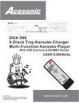
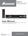
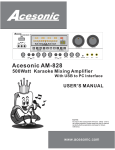
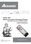
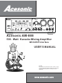
AM-888 500-Watt Dual 32 Bit DSP Karaoke Mixing Amplifier
Acesonic AM-888
500 - Watt Karaoke Mixing Amplifier
With DSP Interface
USER’S MANUAL
NOTE:
To ensure this component will work safely and to
its fullest potential, please read this user’s manual
carefully before operation and keep for future
reference.
www.acesonic.com
Warnings, Cautions and Others
Mises en garde, precautions et indications diverses
For Canada/Pour le Canada
CAUTION
CAUTION: TO PREVENT ELECTRIC SHOCK,
MATCH WIDE BLADE OF PLUG TO WIDE SLOT,AND
FULLY INSERT.
ATTENTION: POUR EVITER LES CHOCS
ELECTRIQUES, INTRODUIRE LA LAME LA PLUS
LARGE DE LA FICHE DANS LA BORNE
CORRESPONDANTE DE LA PRISE ET POUSSER
JUSQUAU FOND.
RISK OF ELECTRIC SHOCK
DO NOT OPEN
CAUTION: TO REDUCE THE RISK OF ELECTRIC SHOCK.
DO NOT REMOVE COVER (OR BACK).
NO USER SERVICEABLE PARTS INSIDE.
REFER SERVICING TO QUALIFIED SERVICE PERSONNEL.
The lightning flash with arrowhead symbol, within an
equilateral triangle is intended to alert the user to the
presence of uninsulated dangerous voltage within the
product's enclosure that may be of sufficient magnitude
to constitute a risk of electric shock to persons.
The exclamation point within an equilateral triangle is
intended to alert the user to the presence of important
operating and maintenance (servicing) instructions in
the literature accompanying the appliance.
For Canada/Pour le Canada
THIS DIGITAL APPARATUS DOES NOT EXCEED
THE CLASS B LIMITS FOR RADIO NOISE
"
AS"SET
EMISSIONS FORM DIGITAL APPARATUS
OUT IN THE INTERFERENCE-CAUSING
"
EQUIPMENT STANDARD "ENTITLED DIGITAL
APPARATUS, ICES-003 OF THE DEPARTMENT OF
COMMUNICATIONS. CET APPAREIL NUMERIQUE
RESPECTE LES LIMITES DE BRUITS RADIO
ELECTRIQUES APPLICABLES AUX APPAREILS
NUMERIQUES DE CLASSE B PRESCRITES DANS
LA NORMESUR LE MATERIEL BROUILLEUR:
APPAREILS NUMERIQUES , NMB-003 EDICTEE
PAR LE MINISTRE DES COMMUNICATIONS.
CAUTION
To reduce the risk of electrical shocks, fire, etc:
1.Do not remove screws, screws, covers or cabinet.
2.Do not expose this appliance to rain or moisture.
FCC INFORMATION (U.S.A.)
1.This equipment has been tested and found to
comply with the limits for a Class B digital device,
pursuant to part 15 of the FCC Rules. These limits
are designed to provide reasonable protection
against harmful interference in a residential
installation.
This equipment generates, uses and can radiate
radio frequency energy and, if not installed and
used in accordance with the instructions, may
cause harmful interference to radio
communications. However, there is no guarantee
that interference will not occur in a particular
installation. If this equipment does cause harmful
interference to radio or television reception, which
can be determined by turning the equipment off and
on, the user is encouraged to try to correct the
interference by one or more of the following
measures:
Reorient or relocate the receiving antenna.
Increase the separation between the equipment
and receiver.
Connect the equipment into an outlet on a circuit
different from that to which the receiver is
connected. Consult the dealer or an experienced
radio/TV technician for help.
Caution
Disconnect the electrical plug to shut off power
completely. The POWER on the unit is not off from the
electrical plug when the POWER button on the front
panel is not pressed in.
IMPORTANT FOR LASER PODUCTS
1. CLASS1 LASER PRODUCT
2. DANGER: Visible laser radiation when open and
interlock failed or defeated. Avoid direct exposure to
beam.
3. CATION: Do not open the top cover. There are no
user service able parts inside the unit. Leave all
servicing to qualified service personnel.
4. REPRODUCTION OF LABEL: CAUTION LABEL,
PLACED INSIDE THE UNIT.
2. IMPORTANT: When connecting this product to
accessories and/or another product use only high
quality shielded cables. Cable(s) supplied with this
product MUST be used. Follow all installation
instructions. Failure to follow instructions could
void your FCC authorization to use product in the
U. S. A.
2
Important Safety instructions
1. Read These Instructions.
2. Keep These Instructions.
3. Heed All Warnings.
4. Follow All Instructions.
5. Do not use this product near water.
6. Clean only with dry cloth.
7. Do not block any ventilation openings.
8. Do not install near any heat sources such as radiators, heat
register, stoves, or other apparatus (including amplifiers)
that produce heat.
9. Do not defeat the safety purpose of the polarized or
grounding-type plug. A polarized plug has two blades with
one wider than the other. A grounding type plug has two
blades and third grounding prong. The wide blade or the
third prong are provided for your safety. If the provided plug
does not fit into your outlet, consult an electrician for
replacement of the obsolete outlet.
10. Protect the power cord from being walked on or pinched
particularly at plugs, convenience receptacles, and the
point where they exit from the apparatus.
11. Only use attachments and accessories specified by the
manufacturer.
12. Use only with the cart, stand, tripod,
bracket, or table specified by the
manufacturer, or sold with the apparatus.
When a cart is used, use caution when
moving the cart.
13. Unplug this apparatus during lightning storms or unused
for long period of time. Apparatus combination to avoid
injury from tip-cover.
14. Refer all servicing to qualified service personnel.
Servicing is required when the apparatus has been
damaged in any way, such as power-supply cord or plug is
damaged, liquid has been spilled or objects have fallen into
the apparatus, the apparatus has been exposed to rain or
moisture, does not operate normally, or has been dropped.
18. Overloading
Do not overload wall outlets, extension cords, or integral
convenience receptacles as this can result in a risk of fire
or electric shock.
19. Object and Liquid Entry
Never push objects of any kind into this product through
openings as they may touch dangerous voltage points or
short-out parts that could result in a fire or electric shock.
Never spill liquid of any kind on the product.
20. Replacement Parts
When replacement parts are required, be sure the service
technician has used replacement parts specified by the
manufacturer or have the same characteristics as the
original part. Unauthorized substitutions may result in fire,
electric shock, or other hazards.
21. Safety Check
Upon completion of any service or repairs to this product,
ask the service technician to perform safety checks to
determine that the product is in proper operating
condition.
22. Wall or Ceiling Mounting
The product should be mounted to a wall or ceiling only as
recommended by the manufacturer. Any mounting of the
product should follow the manufacturer instructions, and
should use a mounting accessory recommended by the
manufacturer.
23. Wet location marking
Apparatus shall not be exposed to dripping or splashing
and no objects filled with liquids, such as vases, shall be
placed on the apparatus.
24. Outdoor Antenna Grounding
If an outside antenna or cable system is connected to the
product, be sure the antenna or cable system is grounded
so as to provide some protection against voltage surges
and built-up static charges. Article 810 of the National
Electrical Code, ANSI/NFPA 70, provides information with
regard to proper grounding of the mast and supporting
structure, grounding of the lead-in wire to an antenna
discharge unit, size of grounding conductors, location of
antenna discharge unit, connection to grounding
electrodes, and requirements for the grounding electrode.
See figure below.
15. This product should be operated only from the type of
power source indicated on the marking label. If you are not
sure of the type of power supply to your home, consult your
product dealer or local power company. For products
intended to operate from battery power, or other sources,
refer to the operating instructions.
16. Protective Attachment Plug
The product is equipped with an attachment plug having
overload protection. This is a safety feature. See
Instruction Manual for replacement or resetting of
protective device. If replacement of the plug is required, be
sure the service technician has used a replacement plug
specified by the manufacturer that has the same overload
protection as the original plug.
17. Power Lines
An outside antenna system should not be located in the
vicinity of overhead power lines or other electric light or
power circuits, or where it can fall into such power lines or
circuits. When installing an outside antenna system,
extreme care should be taken to keep from touching such
power lines or circuits as contact with them might be fatal.
25. Servicing
If your product is not operating correctly or exhibits a
marked change in performance and you are unable to
restore normal operation by following the detailed
procedure in its operating instructions, do not attempt to
service it yourself as operating instructions, do not attempt
to service it yourself as opening or removing covers may
expose you to dangerous voltage or other hazards. Refer
3 all servicing to qualified service personal.
A cesonic AM-888
Thank you for purchasing Acesonic's AM-888. Acesonic takes pride in
providing our costmers with only the most advanced and highest quality
karaoke products on the market. Please read trough this USER’S MANUAL
before operation to ensure proper usage, and keep for future refence. Enjoy!
Table of Contents
Warnings and Caution
Safety Instructions
Table of Contents
Included Accessories
Front Panel Functions and Operation
Rear Panel Functions and Operation
Remote Control Functions
DSP Sound-Effect Setting
Default Volume Setting
Player Connection
Troubleshooting
Specifications
Supplmental User’s Guide
Warranty Information
2
3
4
4
5,6
7,8,9
10
11
12
13,14
15
16
A,B,C,D
17 , 18
Included Accessories
Please check to make sure all accessories are included. If anything
is missing, please contact your dealer immediately.
- 1 Remote Control
- 2 AAA Batteries
- 1 RCA Audio/Video Cable (yellow/red/white)
- 1 AC Power Adapter Cord
- Rack-Mount Kit
- User's Manual
About this Manual
For easy reference, names of all functions and/or
components on the hardware and accessories are denoted
by upper-case letters.
4
Front Panel Function and Operation
EFFECT(ECHO/REVERB) Control
INPUT SELECT
AM-888 500-Watt Dual 32 Bit DSP Karaoke Mixing Amplifier
BBE LEVEL
Low/High Adjustment
MIC Low-Cut Control
1.MUSIC VOL control - Adjusts the volume output for the selected music channels. Turn
counter-clockwise to decrease volume and clock-wise to increase volume.
2.MIC MASTER VOL control - Adjusts the overall volume output for all three microphone
channels, collectively. Turn counter-clockwise to decrease volume and clock-wise to
increase volume.
3.EFFECT VOLUME VOL- Center big knob is used for adjusting the sound effects, echo and
reverberation effects. The two small knobs are used for adjusting high and low frequency
cutting range.
4.INPUT SELECT- Selects the external source connected to DVD INPUT,PDP INPUT,AUX
INPUT or BGM INPUT. Corresponding indicator light will illuminate when selected.
5.KEY CONTROL- These buttons are used for adjusting the music scale. Each step is for1/4
tone adjustment, and the middle button is for the original/standard key. After a song finishes,
or the music has been terminated for more than 4 seconds, the system will automatically
return to the original key.
6.MULTI. - AUDIO(Sound selector)
*CANCEL: The original vocal(usually on the right channel) of the multiplex audio song can be
removed,and only the music(usually on the left channel) would be played.
*PARTNER :If there is no signal detected from Micrphone input(you don’t sing with a
microphone) , the original vocal(right channel) of the multiplex audio song will e automatically
played.Once a signal is detected from Microphone input( you start singing with a
microphone), the original vocal(right channel) will be removed automatically.
*REDUCER: For stero music, only when both left and right channel have vocal, the original
vocal would be removed. This feature might not work very well if the left and right channel
have different voice sound.
*When no indicator light is on, it is the common vocal accompaniment. Nothing changes from
the original audio signal.
7.POWER ON/OFF button - Turns the AM-888 on or off.
8.MIC INPUT jacks (1, A, 2) - 1/4 inch inputs for microphones.
5
Front Panel Function and Operation
EFFECT(ECHO/REVERB) Control
INPUT SELECT
AM-888 500-Watt Dual 32 Bit DSP Karaoke Mixing Amplifier
BBE LEVEL
Low/High Adjustment
MIC Low-Cut Control
9. MIC VOL control (1/A,2/B)- Independently adjusts the signal volume of each
corresponding MICROPHONE INPUT. Turn counter-clockwise to decrease volume and
clockwise to increase volume.
1/A: Adjusts the microphone input level of MIC 1 and MIC A.
2/B: Adjusts the microphone input level of MIC 2 and MIC B*. *MIC B is at the rear of the
machine.
10.MICROPHONE BASS control/MIC TREBLE control- Adjusts the low/high audio
frequency setting from microphone inputs. Turn counter-clockwise to decrease and
clockwise to increase.
11.MUSIC BASS control/MIC TREBLE control- Adjusts the low/high audio frequency
setting from DVD/PDP/AUX/BGM inputs. Turn counter-clockwise to decrease and clockwise
to increase.
12.BALANCE knob- Pans the music output to the stereo left and right channels. Turn
counter-clockwise to gradually pan to the stereo left channel. Turn clockwise to gradually pan
to the stereo right channel. Center the knob for equal output from both stereo left and right
channels. (Please note: the microphone inputs will NOT be affected)
13.MICROPHONE low-cut control- Adjust the low frequency level of microphone input.
14.BBE level adjustment knobs- Adjusts the low/high audio frequency of BBE sound effect.
Turn clockwise to increase and counter-clockwise to decrease.
6
Rear Panel Function and Operation
5
12
6
11
7
8
9
10
1. VOLTAGE SELECTOR- Voltage selection switch. Push the switch right for 115V, and left
for 230V. (Note: Different regions of the world use different voltage strength. Please check to
make sure the correct voltage is selected for your area.). Before switching, please
disconnect the power plug.
2.SPEAKER SYSTEM - Provides audio output to stereo external speakers. Designed to be
used with bare speaker wire as well as banana connectors. The LEFT and RIGHT outputs
each consist of a positive (+, red) and negative (-, black) signal that correspond with the
inputs on each speaker. (Please see connection diagram on page 11 for proper configuration)
*SYSTEM 1: The impedance of speakers should not be lower than 4 Ω.
*SYSTEM 2: The impedance of speakers should not be lower than 4 Ω .
*SYSTEM 1 + 2: The impedance of speakers should not be lower than 8 Ω .
3.SUB OUT jack- This is used for connecting a powered subwoofer, or driving passive
subwoofer via Amplifier.
4.VIDEO OUTPUT 1 &2 jacks - These two VIDEO RCA outputs are used for outputting OSD
video signal and also the video signal which is from DVD/PDP/AUX/BGV. These two VIDEO
output jacks can be use at the same time.
5.VIDEO INPUT jacks (DVD/PDP/AUX/BGV) - VIDEO RCA inputs to receive video signal
from DVD/PDP/AUX/BGV.
6.Microphone B input- Additional microphone input. User can use 2/B MIC VOL control knob
on the front panel to adjust volume.
7.DVD IN AUDIO input- Connect to RCA Audio output jacks of an external component like
DVD(VCD) players.
8.PDP IN AUDIO input- Connect to RCA Audio output jacks of an external component like
Plasma Display Panels.
.8.AUX IN AUDIO input- Connect to RCA Audio output jacks of an external component like
STB AUDIO ouput jacks of CABLE TV .
9.RECORD OUT- Connect to RCA Audio input jacks of an external recording component like
TAPE deck. This Audio output signal is always on even when the external recording
component is not recording.
7
Rear Panel Function and Operation
5
12
6
11
7
8
9
10
11.BGM IN AUDIO input- Connect to RCA Audio output jacks of an external component like
background music devices.
12.PRE-OUT output- Connect to RCA Audio input jacks of an external power amplifier or
Mixing component like Mixer for further signal processing.
13.AC outlet - Female outlet for alternate current adapter. Total power consumption is
300W.Power is always supplied through these outlets regardless of the POWER switch
setting on the front panel, so the power of the connected components should be turn ON/OFF
by using their respective power switches.
14.REMOTE IN - Used for connecting with remote control to increase the signal distance. It
can be connected be wired to the control panel(not included).When it is connected,the
receiver at frontpanel would NOT work.
15.MIC RETURN- Outputs pure microphone signal to external component.
16.MIC SEND- O utputs mixed microphone signal to external component.
17.CENTER OUT- Please refer to the “CENTER OUT” section in the supplemental User’s
Guide.
18.REAR MIC INPUT- the 3rd/C microphone input and volume adjustment knob.
19.DVD SENSITIVITY SWITCH- Sets the sensitivity at which DVD audio input level is
detected and switched automatically.
*L:Set to this position when the input switch does not change to BGM or other mode even if
DVD playback is finished.
*M:Set to this position in normal operating condition.
*H:Set to this position when you want to cange the input switch to other modes even when a
DVD is playing.
20.PDP SENSITIVITY SWITCH- Sets the sensitivity at which PDP audio input level is
detected and switched automatically.
*L:Set to this position when the input switch does not change to BGM or other mode even if
the playback from PDP source is finished
*M:Set to this position in normal operating condition.
*H:Set to this position when you want to cange the input switch to other modes even if PDP
source is playing..
8
Rear Panel Function and Operation
5
12
6
11
7
8
9
10
21.AUX SENSITIVITY SWITCH- Sets the sensitivity at which AUX audio input level is
detected and switched automatically.
*L:Set to this position when the input switch does not change to BGM or other mode even if
the playback from AUX source is finished
*M:Set to this position in normal operating condition.
*H:Set to this position when you want to canges the input switch to other modes even if
AUX source is playing.
22.MONO/BGM STEREO SWITCH- Set this switch to “STEREO” when the BGM input is in
stereo, or to “MONO” when it is in monaural.
23.BGM INPUT LEVEL control- Adjust this control to the volume of background music.
24.GROUND TERMINAL- This is used for grounding under certin conditions. Mainly for
avoiding electric shock or electric leakage.
25.AC POWER Cord- Plug this core into an AC Wall outlet.
26.INPUT LEVEL adjustment- This is used for fine-tuning the audio frequency signals
inputted from DVD,DPD,and AUX.
9
Remote Control:
MIC EFFECT
Select from:
ECHO+REVERB/DELAY+REVERB/REVERB/ECHO
MIC EFFECT
INPUT SELECTOR
INPUT SELECT
Select from:
DVD/PDP/AUD/BGM input audio/video signals
ECHO+REV DEL+REV
1
2
REVERB
ECHO
3
4
#
PARAM
OSD
b
REV
ECHO
VOICE
SUB
MUTE
BBE
SOUND EFFECT
MIC
MUSIC
WOOFER
CENTER
VOLUME
Parameter Adjustment
OSD:Enter the function, sound-effect setting pages. Can
be used to turn pages as well. Use up/down/left/right
arrow key for operation.
EXIT:Exit from the function, sound-effect setting page.
.KEY CONTROL:
1.SHARP button (#)- raises music key by one halftone.
2.NATURAL button ( )- resets music to original key.
3.FLAT button (b)- lowers music key by one half-tone.
VOLUME:
1 . REV : Microphone reverb effect adjustment
2 . ECHO : Microphone echo effect adjustment
3 . MIC : Microphone volume adjustment
4 . MUSIC : Music volume adjustment
5 . WOOFER : Woofer volume adjustment
6 . CENTER : Center volume adjustment
SOUND EFFECT
1.VOICE: Mult . selection on voice and music.
2.MUTE: To enable/disable the sound.
3.SUB: Switch to subwoofer output(need to connect to
active subwoofer)
4.BBE:To enable/disable the dynamic expand effect.
10
Sound-Effect Screen Setting:
B
11
Default Volume Setting:
INPUT SEL
Default Volume and Maximum Volume Setting:
1.Make sure the AM-888 is connect to power and turn POWER SWITCH(#7) OFF.
2.Counterclockwise turns the volume of MUSIC VOLUME(#1) and MIC MASTER VOL(#2) to
minimum.
3.Continually press INPUT SEL(#4), and then press POWER SWTICH(#7). The indicator light
of MIC MASTER VOL (#2) will be on, and “MIC INITIAL” will appear on the OSD.
4. AM-888 is under microphone initial volume setting. The default value would be the initial
value of microphone volume. Clockwise turns the MIC MASTER VOL(#2) to change the initial
volume, and press KEY RETURN(#13) to go to next step.
5.”MIC MAX” now appears on OSD(On-screen Display) . This m eans the AM-888 is under
microphone max. Volume setting. The maximum value means the maximum MIC volume can be
reached by using the remote control or other outside control signals. After finishing setting,
press KEY RETURN(#13) to go to next step.
6.The indicator light of MIC MASTER VOL(#2) is off, and the indicator light of MUSIC MASTER
VOL is on.”MUSIC INITIAL” now appears on OSD(On-screen Display).This means the AM-888
is under MUSIC VOL setting.
7.Turn clockwise at MUSIC VOL(#1) to set up the initial value of the MUSIC VOL, and press
KEY RETURN(#13) to go to the next step.
8.”MUSIC MAX” appears on the OSD(On-screen Display),this means AM-888 is under music
max. Volume setting. The maximum value means the maximum music volume can be reached
by using remote control or other outside control signals. After finishing making changes, press
KEY RETURN(#13) to go to next step.
9.When LED Display of boot appears on the front panel of AM-888, the process of setting is
done.
10. To cancel/exit the set up mode, press the right button of the Key Control(#5).When LED
Displayof boot appears on the front panel of the AM-888, the process of setting has been
canceled.
12
Player Connections
Make sure all power is disconnected from each component before connecting. Plug all cables
and cords securely to prevent unwanted noise.
Karaoke/media player and AM-888:
Karaoke /Media Player
DGX-106
KARAOKE OUTPUT
Acesonic AM-888
M i c r o p h o n e a n d A M -888:
Acesonic AM-888
To Microphone
TV with Audio and AM-888:
Acesonic AM-888
13
Player Connections
Home Stereo Speaker and AM-888:
10
14
Troubleshooting
If you are having problems operating the AM-888, or suspect something is wrong with the unit,
please check the troubleshoot list below to see if the issue is a result of incorrect operation
rather than equipment malfunction. If you are still unable to resolve the problem, please
contact our Acesonic service center at 626-820-0670.
Symptom
Will not turn on
No audio can be
heard, audio signal
meter shows signal
Possible Causes
Check both the AC adapter connection as well as the AC outlet connection.
AC power adapter cord is
incorrectly attached or not
plugged into outlet
Incorrect input source selected Check to make sure the correct corresponding button is pressed on the input
selector in relation to your audio source.
MUTE button is ON, or MUSIC
VOL control is down
No audio can be
heard, audio signal
meter DOES NOT
show signal
No microphone
signal can be heard
Solution
Poor or incorrect output
connection to speakers or other
external units, or bad/defective
cables, wires or connectors
Poor or incorrect input
connection from audio source
unit, or bad/defective cables,
wires or connectors
Microphone controls are turned
down
Press the MUTE button once or check to see if MUSIC VOL control is all the way
down. If so, turn the knob slowly clockwise.
Double check all output connections to speakers or other units. Try using another
set of cables/cords. Make sure to turn POWER OFF before reconnecting cables.
Double check all input connections from audio source units. Try using another set
of cables/cords. Make sure to turn POWER OFF before reconnecting cables.
Check MIC MASTER VOL and all MIC VOL controls to see if they are turned
down. If so, turn the knob slowly clockwise.
Poor or incorrect input
Double check all microphone connections. Try using another cable/cord. Make
connection from microphone, or sure to turn MIC MASTER VOL down before reconnecting cables.
bad/defective cables, wires or
connectors.
Music sounds hollow
or distant
PARTNER function is ON
No vocals present in
source that normally
contains vocals
Unpleasant howling
and screeching heard
from speakers
Press the MULTI AUDIO button once, or press the STEREO button once.
PARTNER button is ON, or
RIGHT channel button selected
on a multiplex* source
Microphone feedback
Place microphones further away from speakers. Face microphones away from
speakers.
Remote control not
functioning
Batteries are exhausted or
positioned incorrectly
Replace with fresh batteries or double check battery positioning.
Remote is out of range or there
is an obstruction
Move closer to the AM-888 or make sure no objects are obstructing your view of
the unit.
If you do not want to eliminate vocals from the source, press the MULTI AUDIO
button once to return music to original characteristics.
* Multiplex refers to karaoke music designed to allow lead vocals to be turned on/off by
isolating them to just the left channel.
15
Specifications
AM-888 Specifications
1 Year Manufacturer Warranty
Lifetime Technical Support
CE/FCC/FDA certified
Design/Made in Taiwan
Technical Support: (626)820-0670
Address:161 South 8th Avenue City Of Industry,
CA 91746-3208, USA
Website: www.acesonic.com
16
Supplemental User’s Guide
volume. Besides, the optimized and
fixed
volume
setting
between
background music and microphone is
convenient for users. It needs no extra
adjustments on volume when turning
on the system. With this function, we
can say goodbye to the unnecessary
troubles resulted by miss-hitting the
volume button.
Co
C ngratulation for you choosing AM-888
Professional Karaoke Amplifier! This is
an absolutely correct decision. If you
are a singing-lover, you will thoroughly
forget the traditional echo karaoke
Amplifier after experiencing The AM-888.TheAM-888
.
is a DSP REVERB work-of-art with
robust and powerful functionalities and
able to make your performance as
elegant and enchanting as professional
singers can reach. Singer’s breathing
or tone-changing can be exactly
visually and acoustically synchronized
and reach an optimized effect. For
Beginners,AM-888 would be able to lead
you to the most correct and proper
manners and skills for signing.
2. SUB
Crossover Point Adjustment for
Subwoofer. The range is between
50Hz ~ 150 Hz. Besides enhancing
the atmosphere and mood, the SUB
function
can
compensate
the
insufficient subwoofer effects on Left /
Right Channels. When we adjust this
function, it would be acceptable when
there is no bass reflection resonance
rumbled in the whole space. It is
suggested to slightly fade the MUSIC
TONE (BASS) of Left/Right Channels.
This can ensure a solider and clearer
performance of subwoofer.
AM-888 Has built-in 32bit Hi-Speed
Digital-Process DSP ECHO and
REVERB – Hi-Power-Output TWO
Channel Amplifier. If the space is
sufficient, it is suggested to connect the
Mid-channel of AM-888 with another
amplifier, and also connect the active
subwoofer. With proper adjustments,
the acoustic range of voice would be
much wider, and the position of human
voice
would
be
much
more
Concentrated. It is suggested to get
more advices from experienced
professionals when considering to
purchase microphone and speakers, in
order to obtain the best performances
Of AM-888. Especially in an airtight space
(Living room, KTV room…etc),AM-888 can
easily overcome various acoustic
problems, and grant you a crystal-clear
voice.
3. Hi-CUT
Eliminate the hiss resulted from
labiodentals and microphone. In some
cases, when we collocate the amplifier
and the microphone, there would be
the protrude Hi-Frequency response
issue, and will lead to the problem of
labiodentals hiss and some feedbacks.
This function can avoid these problems
from occurring.
After the proper
adjustment, we can use MIC-TONE
(TREBLE) function to fine-tune and
compensate.
4. MIC LOW CUT
Eliminate the Low-Frequency feedback
of the microphone. Basically, the
Low-Frequency feedback of the
microphone is a problem that most of
the karaoke systems can’t overcome.
This problem comes from the amplifier
locations at different height, and the
reflection of microphone’s nature. This
is the problem that MIC-TONE(BASS)
can’t handle; however, MIC LOW CUT
Function can help to shot this trouble.
Guide for Major Functions on the
Front Panel
1. MIC MASTER / MUSIC VOL
In addition to function as the volume
adjustment
for
the
usage
of
microphone and karaoke music, users
can enter the max./min. volume
settings by pressing the OSD button on
the remote control. This function is
designed to avoid the instruments from
Damages
resulting
from excessive
A
AM-888
AM-888
effect
REVERB effect is activated, users can
feel the dynamic sound effect.
AM-888
ACESONIC LIMITED WARRANTY
WARRANTY PROCEDURE
TO VALIDATE YOUR WARRANTY: Fill out the attached warranty card, be sure to include the model and serial number of
the unit since this is how warranties are tracked. If your Acesonic product was purchased in the U.S., mail the completed
card directly to Acesonic within 10 days from the date of purchase. If you purchased the product outside the U.S . you
must file your warranty registration card with the Distributor in that country. It is advised that you keep your bill of sale as
proof of purchase, should any difficulties arise concerning the registration of the warranty card.
WARRANTY REGISTRATION is made and tracked by MODEL AND SERIAL NUMBER ONLY, not by the purchaser's or
owner name. Therefore any warranty correspondence or inquiries MUST include the model and serial number of the
product in question. Be sure to fill in the model and serial number in the space provided below and keep this portion of the
warranty card in a safe place for future reference.
WARRANTY SERVICE MUST BE PERFORMED ONLY BY AN AUTHORIZED ACESONIC SERVICE FACILITY LOCATED
IN THE COUNTRY WHERE THE UNIT WAS PURCHASED,OR AT THE ACESONIC HEADQUARTER IN THE U.S.It is
recommended that advance notice be given to the repair facility to avoid needless shipment in case the problem can be
solved over the phone. UNAUTHORIZED SERVICE PERFORMED WILL VOID ANY EXISTING FACTORY WARRANTY
ON THAT PRODUCT.
FACTORY SERVICE: if you wish your product to be serviced at the factory, it must be shipped FULLY INSURED, IN THE
ORIGINAL PACKING OR EQUIVALENT. This warranty will NOT cover repairs on products damaged through improper
packaging. If possible, avoid sending products through the mail. Be sure to include in the package:
1 . Complete return shipping address (P.O. Box numbers are NOT acceptable).
2 . A detailed description of any problems experienced, including the make and model numbers of any other equipment in
the system.
Repaired products will be returned freight C.O.D. unless sufficient return shipment funds are included with the unit.
Products sent to the factory from outside the U.S. MUST include return freight funds, and the sender is fully responsible for
all, customs procedures, duties, tariffs and deposits.
RECORD THE MODEL AND SERIAL NUMBER BELOW AND RETAIN THIS PORTION OF THE WARRANTY
CARD FOR YOUR FILES:
MODEL ACESONIC AM-888
SERIAL NUMBER
DATE OF PURCHASE
---------------------------------------------------------------Detach this portion and mail it to the factory
MODEL ACESONIC AM-888 SERIAL NO.
PURCHASE DATE
OWNER'S NAME
CITY
ADDRESS
STATE
E-MAIL ADDRESS
ZIP
TELEPHONE
The following information is appreciated, but not required:
Dealer's name and address:
What other products and/or product changes would you like to see Manufactured?
Any other comments:
17
LIMITED DOMESTIC WARRANTY
ACESONIC WARRANTS ALL PRODUCTS PURCHASED IN THE U .S . AGAINST DEFECTS IN MATERIAL OR WORK MANSHIP FOR A PERIOD OF ONE(1) YEAR FROM THE INITIAL DATE OF RETAIL PURCHASE FROM AN
AUTHORIZED ACESONIC DEALER, OR, ONE(1) YEAR FROM THE DATE OF MANUFACTURE IF PROOF OF
PURCHASE DATE IS NOT AVAILABLE. This limited warranty extends to all purchasers or owner of the product
during the warranty period beginning with the original retail purchase. Acesonic does not, however, warrant its products
against any and all defects : 1) arising out of material or workmanship not provided or furnished by Acesonic, or 2)
resulting from abnormal use of the product or use in violation of instruction, or 3) in products repaired or serviced by
other than authorized Acesonic repair facilities, or 4) in products with removed or defaced serial numbers, or 5) in
components or parts or products expressly warranted by another manufacturer. Acesonic agrees to supply all parts
and labor to repair or replace defects covered by this limited warranty with parts or products of original or improved
design, at its option in each respect, if the defective product is shipped prior to the end of warranty period to any
authorized warranty repair facility in U.S., or to the Acesonic in the original packaging or a replacement supplied by
Acesonic, with all transportation costs and full insurance paid each way by the purchaser or owner.
LIMITED WARRANTY OUTSIDE THE U.S.
ACESONIC PRODUCTS ARE WARRANTED ONLY IN THE COUNTRY WHERE PURCHASED,THROUGH THE AUTHORIZED ACESONIC DISTRIBUTOR IN THAT COUNTRY, AGAINST DEFECTS IN MATERIAL OR WORKMANSHIP. THE
SPECIFIC PERIOD OF THIS LIMITED WARRANTY SHALL BE THAT WHICH IS DESCRIBED TO THE ORIGINAL RETAIL
PURCHASE BY THE AUTHORIZED DEALER OR DISTRIBUTOR AT THE TIME OF PURCHASE.
Acesonic does not, however, warrant its products against any and all defects: 1) arising out of material or workmanship
not provided or furnished by Acesonic, or 2) resulting from abnormal use of the product or use in violation of instructions,
or 3) in products repaired or serviced by other than authorized Acesonic repair facilities, or 4) in products with removed or
defaced serial numbers, or 5) in components or parts or products expressly warranted by another manufacturer. Acesonic
agrees through the applicable authorized distributor, to repair or replace defects covered by this limited warranty with
parts or product of original or improved design, at its option in each respect, if the defective product is shipped prior to the
end of the warranty period to designated authorized Acesonic warranty repair facility in the country where purchased, or
to Acesonic Headquarters in the U.S., in the original packaging or a replacement supplied by Acesonic , with all
transportation costs and full insurance paid each way by the purchaser or owner.
ALL REMEDIES AND THE MEASURE OF DAMAGES ARE LIMITED TO THE ABOVE SERVICES. IT IS POSSIBLE THAT
ECONOMIC LOSS OR INJURY TO PERSON OR PROPERTY MAY RESULT FROM THE OF THE PRODUCT;
HOWEVER, EVEN IF ACESONIC HAS BEEN ADVISED OF THIS POSSIBILITY, THIS LIMITED WARRANTY DOES NOT
COVER ANY SUCH CONSEQUENTIAL OR INCIDENTAL DAMAGES. SOME STATES OR COUNTRIES DO NOT ALLOW
THE LIMITATIONS OR EXCLUSIONS OF INCIDENTAL OR CONSEQUENTAL DAMAGES, SO THE ABOVE LIMITATION
MAY NOT APPLY TO YOU.
ANY AND ALL WARRANTIES, EXPRESSED OR IMPLIED, ARISING BY LAW, COURSE OF DEALING, COURSE OF
PERFORMANCE, USAGE OF TRADE, OR OTHERWISE, INCLUDING BUT NOT LIMITED TO IMPLIED WARRANTIES
OF MERCHANTABILITY AND FITNESS FOR A PARTICULAR PURPOSE, ARE LIMITED TO A PERIOD OF ONE(1) YEAR
FROM EITHER THE DATE OF ORIGINAL RETAIL PURCHASE OR, IN THE EVENT NO PROOF OF PURCHASE DATE IS
AVAILABLE, THE DATE OF MANUFACTURE, SOME STATES OR COUNTRIES DO NOT ALLOW LIMITATIONS ON HOW
LONG AN IMPLIED WARRANTY LASTS, SO THE ABOVE LIMITATIONS MAY NOT APPLY TO YOU.
THE LIMITED WARRANTY GIVES YOU SPECIFIC LEGAL RIGHTS, AND YOU MAY ALSO HAVE OTHER RIGHTS THAT
VARY FROM STATE TO STATE,COUNTRY TO COUNTRY.
-------------------------------------------------------------------Please Mail To:
Acesonic Corp.
161 S. 8th Ave
City of Industry CA, 91746
USA
18