1
Ethernet Card Software Feature and
Configuration Guide
For the Cisco ONS 15454, Cisco ONS 15454 SDH, and Cisco ONS 15327
Cisco IOS Release 12.2 (29a) sv
CTC and Documentation Release 7.2
Last Updated: January 2009
Corporate Headquarters
Cisco Systems, Inc.
170 West Tasman Drive
San Jose, CA 95134-1706
USA
http://www.cisco.com
Tel: 408 526-4000
800 553-NETS (6387)
Fax: 408 526-4100
Text Part Number: 78-17736-02
THE SPECIFICATIONS AND INFORMATION REGARDING THE PRODUCTS IN THIS MANUAL ARE SUBJECT TO CHANGE WITHOUT NOTICE. ALL
STATEMENTS, INFORMATION, AND RECOMMENDATIONS IN THIS MANUAL ARE BELIEVED TO BE ACCURATE BUT ARE PRESENTED WITHOUT
WARRANTY OF ANY KIND, EXPRESS OR IMPLIED. USERS MUST TAKE FULL RESPONSIBILITY FOR THEIR APPLICATION OF ANY PRODUCTS.
THE SOFTWARE LICENSE AND LIMITED WARRANTY FOR THE ACCOMPANYING PRODUCT ARE SET FORTH IN THE INFORMATION PACKET THAT
SHIPPED WITH THE PRODUCT AND ARE INCORPORATED HEREIN BY THIS REFERENCE. IF YOU ARE UNABLE TO LOCATE THE SOFTWARE LICENSE
OR LIMITED WARRANTY, CONTACT YOUR CISCO REPRESENTATIVE FOR A COPY.
The following information is for FCC compliance of Class A devices: This equipment has been tested and found to comply with the limits for a Class A digital device, pursuant
to part 15 of the FCC rules. These limits are designed to provide reasonable protection against harmful interference when the equipment is operated in a commercial
environment. This equipment generates, uses, and can radiate radio-frequency energy and, if not installed and used in accordance with the instruction manual, may cause
harmful interference to radio communications. Operation of this equipment in a residential area is likely to cause harmful interference, in which case users will be required
to correct the interference at their own expense.
The following information is for FCC compliance of Class B devices: The equipment described in this manual generates and may radiate radio-frequency energy. If it is not
installed in accordance with Cisco’s installation instructions, it may cause interference with radio and television reception. This equipment has been tested and found to
comply with the limits for a Class B digital device in accordance with the specifications in part 15 of the FCC rules. These specifications are designed to provide reasonable
protection against such interference in a residential installation. However, there is no guarantee that interference will not occur in a particular installation.
Modifying the equipment without Cisco’s written authorization may result in the equipment no longer complying with FCC requirements for Class A or Class B digital
devices. In that event, your right to use the equipment may be limited by FCC regulations, and you may be required to correct any interference to radio or television
communications at your own expense.
You can determine whether your equipment is causing interference by turning it off. If the interference stops, it was probably caused by the Cisco equipment or one of its
peripheral devices. If the equipment causes interference to radio or television reception, try to correct the interference by using one or more of the following measures:
• Turn the television or radio antenna until the interference stops.
• Move the equipment to one side or the other of the television or radio.
• Move the equipment farther away from the television or radio.
• Plug the equipment into an outlet that is on a different circuit from the television or radio. (That is, make certain the equipment and the television or radio are on circuits
controlled by different circuit breakers or fuses.)
Modifications to this product not authorized by Cisco Systems, Inc. could void the FCC approval and negate your authority to operate the product.
The Cisco implementation of TCP header compression is an adaptation of a program developed by the University of California, Berkeley (UCB) as part of UCB’s public
domain version of the UNIX operating system. All rights reserved. Copyright © 1981, Regents of the University of California.
NOTWITHSTANDING ANY OTHER WARRANTY HEREIN, ALL DOCUMENT FILES AND SOFTWARE OF THESE SUPPLIERS ARE PROVIDED “AS IS” WITH
ALL FAULTS. CISCO AND THE ABOVE-NAMED SUPPLIERS DISCLAIM ALL WARRANTIES, EXPRESSED OR IMPLIED, INCLUDING, WITHOUT
LIMITATION, THOSE OF MERCHANTABILITY, FITNESS FOR A PARTICULAR PURPOSE AND NONINFRINGEMENT OR ARISING FROM A COURSE OF
DEALING, USAGE, OR TRADE PRACTICE.
IN NO EVENT SHALL CISCO OR ITS SUPPLIERS BE LIABLE FOR ANY INDIRECT, SPECIAL, CONSEQUENTIAL, OR INCIDENTAL DAMAGES, INCLUDING,
WITHOUT LIMITATION, LOST PROFITS OR LOSS OR DAMAGE TO DATA ARISING OUT OF THE USE OR INABILITY TO USE THIS MANUAL, EVEN IF CISCO
OR ITS SUPPLIERS HAVE BEEN ADVISED OF THE POSSIBILITY OF SUCH DAMAGES.
CCDE, CCENT, Cisco Eos, Cisco HealthPresence, the Cisco logo, Cisco Lumin, Cisco Nexus, Cisco StadiumVision, Cisco TelePresence, Cisco WebEx, DCE, and Welcome
to the Human Network are trademarks; Changing the Way We Work, Live, Play, and Learn and Cisco Store are service marks; and Access Registrar, Aironet, AsyncOS,
Bringing the Meeting To You, Catalyst, CCDA, CCDP, CCIE, CCIP, CCNA, CCNP, CCSP, CCVP, Cisco, the Cisco Certified Internetwork Expert logo, Cisco IOS,
Cisco Press, Cisco Systems, Cisco Systems Capital, the Cisco Systems logo, Cisco Unity, Collaboration Without Limitation, EtherFast, EtherSwitch, Event Center, Fast Step,
Follow Me Browsing, FormShare, GigaDrive, HomeLink, Internet Quotient, IOS, iPhone, iQuick Study, IronPort, the IronPort logo, LightStream, Linksys, MediaTone,
MeetingPlace, MeetingPlace Chime Sound, MGX, Networkers, Networking Academy, Network Registrar, PCNow, PIX, PowerPanels, ProConnect, ScriptShare, SenderBase,
SMARTnet, Spectrum Expert, StackWise, The Fastest Way to Increase Your Internet Quotient, TransPath, WebEx, and the WebEx logo are registered trademarks of
Cisco Systems, Inc. and/or its affiliates in the United States and certain other countries.
All other trademarks mentioned in this document or website are the property of their respective owners. The use of the word partner does not imply a partnership relationship
between Cisco and any other company. (0812R)
Any Internet Protocol (IP) addresses used in this document are not intended to be actual addresses. Any examples, command display output, and figures included in the
document are shown for illustrative purposes only. Any use of actual IP addresses in illustrative content is unintentional and coincidental.
Ethernet Card Software Feature and Configuration Guide for the Cisco ONS 15454, Cisco ONS 15454 SDH, and Cisco ONS 15327, Release 7.2
© 2000–2009 Cisco Systems, Inc. All rights reserved.
CONTENTS
About this Guide
xxvii
Revision History
xxvii
Document Objectives xxviii
Audience
xxviii
Document Organization
xxviii
Related Documentation
xxx
Document Conventions
xxxi
Obtaining Optical Networking Information xxxvi
Where to Find Safety and Warning Information xxxvii
Cisco Optical Networking Product Documentation CD-ROM
Obtaining Documentation and Submitting a Service Request
CHAPTER
1
ML-Series Card Overview
CHAPTER
2
CTC Operations
xxxvii
1-1
ML-Series Card Description
ML-Series Feature List
xxxvii
1-1
1-2
2-1
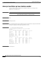
Displaying ML-Series POS And Ethernet Statistics on CTC
2-1
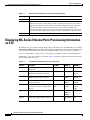
Displaying ML-Series Ethernet Ports Provisioning Information on CTC
Displaying ML-Series POS Ports Provisioning Information on CTC
Provisioning Card Mode
Displaying the FPGA Information
Provisioning SONET/SDH Circuits
CHAPTER
3
2-3
2-4
Managing SONET/SDH Alarms
J1 Path Trace
2-2
2-4
2-4
2-5
2-5
Initial Configuration
3-1
Hardware Installation
3-1
Cisco IOS on the ML-Series Card 3-2
Opening a Cisco IOS Session Using CTC 3-2
Telnetting to the Node IP Address and Slot Number
Telnetting to a Management Port 3-4
3-3
Ethernet Card Software Feature and Configuration Guide, R7.2
January 2009
iii
Contents
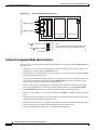
ML-Series IOS CLI Console Port 3-4
RJ-11 to RJ-45 Console Cable Adapter 3-5
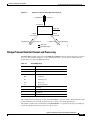
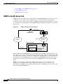
Connecting a PC or Terminal to the Console Port
3-5
Startup Configuration File 3-7
Manually Creating a Startup Configuration File Through the Serial Console Port
Passwords 3-8
Configuring the Management Port 3-8
Configuring the Hostname 3-9
CTC and the Startup Configuration File 3-9
Loading a Cisco IOS Startup Configuration File Through CTC 3-10
Database Restore of the Startup Configuration File 3-11
Multiple Microcode Images
3-11
Changing the Working Microcode Image
CHAPTER
4
Cisco IOS Command Modes
3-13
Using the Command Modes
Exit 3-15
Getting Help 3-15
3-15
Configuring Interfaces
3-7
3-12
4-1
General Interface Guidelines
MAC Addresses 4-2
Interface Port ID 4-2
4-1
Basic Interface Configuration
4-3
Basic Fast Ethernet, Gigabit Ethernet, and POS Interface Configuration 4-4
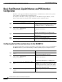
Configuring the Fast Ethernet Interfaces for the ML100T-12 4-4
Configuring the Fast Ethernet Interfaces for the ML100X-8 4-5
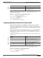
Configuring the Gigabit Ethernet Interface for the ML1000-2 4-6
Configuring Gigabit Ethernet Remote Failure Indication (RFI) 4-7
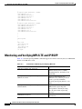
Monitoring and Verifying Gigabit Ethernet Remote Failure Indication (RFI) 4-8
Configuring the POS Interfaces (ML100T-12, ML100X-8 and ML1000-2) 4-10
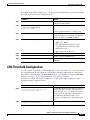
CRC Threshold Configuration
4-11
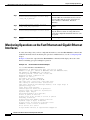
Monitoring Operations on the Fast Ethernet and Gigabit Ethernet Interfaces
CHAPTER
5
Configuring POS
4-12
5-1
POS on the ML-Series Card 5-1
ML-Series SONET and SDH Circuit Sizes
VCAT 5-2
SW-LCAS 5-3
5-1
Ethernet Card Software Feature and Configuration Guide, R7.2
iv
January 2009
Contents
Framing Mode, Encapsulation, and CRC Support 5-4
Configuring POS Interface Framing Mode 5-4
Configuring POS Interface Encapsulation Type 5-4
Configuring POS Interface CRC Size in HDLC Framing 5-5
Setting the MTU Size 5-5
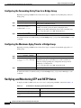
Configuring Keep Alive Messages 5-6
SONET/SDH Alarms 5-6
Configuring SONET/SDH Alarms 5-7
Configuring SONET/SDH Delay Triggers 5-7
Configuring SONET/SDH Alarms 5-7
C2 Byte and Scrambling 5-8
Third-Party POS Interfaces C2 Byte and Scrambling Values 5-9
Configuring SPE Scrambling 5-9
Monitoring and Verifying POS
5-9
POS Configuration Examples 5-11
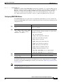
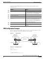
ML-Series Card to ML-Series Card 5-11
ML-Series Card to Cisco 12000 GSR-Series Router 5-12
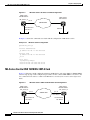
ML-Series Card to G-Series Card 5-13
ML-Series Card to ONS 15310 ML-100T-8 Card 5-14
CHAPTER
6
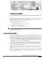
Configuring Bridges
6-1
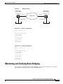
Understanding Basic Bridging
Configuring Basic Bridging
6-1
6-2
Monitoring and Verifying Basic Bridging
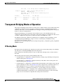
Transparent Bridging Modes of Operation
IP Routing Mode 6-5
6-3
6-5
No IP Routing Mode 6-6
Bridge CRB Mode 6-7
Bridge IRB Mode 6-8
CHAPTER
7
Configuring STP and RSTP
7-1
STP Features 7-1
STP Overview 7-2
Supported STP Instances 7-2
Bridge Protocol Data Units 7-2
Election of the Root Switch 7-3
Bridge ID, Switch Priority, and Extended System ID
Spanning-Tree Timers 7-4
Creating the Spanning-Tree Topology 7-4
7-4
Ethernet Card Software Feature and Configuration Guide, R7.2
January 2009
v
Contents
Spanning-Tree Interface States 7-5
Blocking State 7-6
Listening State 7-7
Learning State 7-7
Forwarding State 7-7
Disabled State 7-7
Spanning-Tree Address Management 7-8
STP and IEEE 802.1Q Trunks 7-8
Spanning Tree and Redundant Connectivity 7-8
Accelerated Aging to Retain Connectivity 7-9
RSTP 7-9
Supported RSTP Instances 7-9
Port Roles and the Active Topology 7-9
Rapid Convergence 7-10
Synchronization of Port Roles 7-12
Bridge Protocol Data Unit Format and Processing 7-13
Processing Superior BPDU Information 7-14
Processing Inferior BPDU Information 7-14
Topology Changes 7-14
Interoperability with IEEE 802.1D STP
7-15
Configuring STP and RSTP Features 7-15
Default STP and RSTP Configuration 7-16
Disabling STP and RSTP 7-16
Configuring the Root Switch 7-17
Configuring the Port Priority 7-17
Configuring the Path Cost 7-18
Configuring the Switch Priority of a Bridge Group 7-19
Configuring the Hello Time 7-19
Configuring the Forwarding-Delay Time for a Bridge Group 7-20
Configuring the Maximum-Aging Time for a Bridge Group 7-20
Verifying and Monitoring STP and RSTP Status
CHAPTER
8
Configuring VLANs
7-20
8-1
Understanding VLANs
8-1
Configuring IEEE 802.1Q VLAN Encapsulation
IEEE 802.1Q VLAN Configuration
8-2
8-3
Monitoring and Verifying VLAN Operation
8-5
Ethernet Card Software Feature and Configuration Guide, R7.2
vi
January 2009
Contents
CHAPTER
9
Configuring IEEE 802.1Q Tunneling and Layer 2 Protocol Tunneling
Understanding IEEE 802.1Q Tunneling
9-1
9-1
Configuring IEEE 802.1Q Tunneling 9-4
IEEE 802.1Q Tunneling and Compatibility with Other Features
Configuring an IEEE 802.1Q Tunneling Port 9-4
IEEE 802.1Q Example 9-5
Understanding VLAN-Transparent and VLAN-Specific Services
9-4
9-6
VLAN-Transparent and VLAN-Specific Services Configuration Example
Understanding Layer 2 Protocol Tunneling
9-7
9-9
Configuring Layer 2 Protocol Tunneling 9-10
Default Layer 2 Protocol Tunneling Configuration 9-10
Layer 2 Protocol Tunneling Configuration Guidelines 9-11
Configuring Layer 2 Tunneling on a Port 9-11
Configuring Layer 2 Tunneling Per-VLAN 9-12
Monitoring and Verifying Tunneling Status 9-12
CHAPTER
10
Configuring Link Aggregation
10-1
Understanding Link Aggregation 10-1
Configuring EtherChannel 10-2
EtherChannel Configuration Example 10-3
Configuring POS Channel 10-4
POS Channel Configuration Example 10-5
Understanding Encapsulation over EtherChannel or POS Channel 10-7
Configuring Encapsulation over EtherChannel or POS Channel 10-7
Encapsulation over EtherChannel Example 10-7
Monitoring and Verifying EtherChannel and POS
CHAPTER
11
Configuring Networking Protocols
10-9
11-1
Basic IP Routing Protocol Configuration
RIP 11-2
EIGRP 11-2
OSPF 11-2
BGP 11-3
Enabling IP Routing 11-3
11-1
Configuring IP Routing 11-4
Configuring RIP 11-4
RIP Authentication 11-7
Summary Addresses and Split Horizon
11-8
Ethernet Card Software Feature and Configuration Guide, R7.2
January 2009
vii
Contents
Configuring OSPF 11-9
OSPF Interface Parameters 11-13
OSPF Area Parameters 11-14
Other OSPF Behavior Parameters 11-16
Change LSA Group Pacing 11-18
Loopback Interface 11-19
Monitoring OSPF 11-19
Configuring EIGRP 11-20
EIGRP Router Mode Commands 11-22
EIGRP Interface Mode Commands 11-23
Configure EIGRP Route Authentication 11-25
Monitoring and Maintaining EIGRP 11-26
Border Gateway Protocol and Classless Interdomain Routing
Configuring BGP 11-27
Verifying the BGP Configuration 11-28
Configuring IS-IS 11-29
Verifying the IS-IS Configuration 11-30
Configuring Static Routes
11-31
Monitoring Static Routes
11-32
Monitoring and Maintaining the IP Network
11-33
Understanding IP Multicast Routing 11-33
Configuring IP Multicast Routing 11-34
Monitoring and Verifying IP Multicast Operation
CHAPTER
12
Configuring IRB
Configuring IRB
12-3
Monitoring and Verifying IRB
Configuring VRF Lite
Configuring VRF Lite
12-4
13-1
Understanding VRF Lite
13-1
13-2
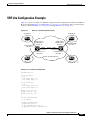
VRF Lite Configuration Example
13-3
Monitoring and Verifying VRF Lite
CHAPTER
14
12-1
12-2
IRB Configuration Example
13
11-35
12-1
Understanding Integrated Routing and Bridging
CHAPTER
11-27
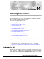
Configuring Quality of Service
Understanding QoS
13-7
14-1
14-1
Ethernet Card Software Feature and Configuration Guide, R7.2
viii
January 2009
Contents
Priority Mechanism in IP and Ethernet 14-2
IP Precedence and Differentiated Services Code Point
Ethernet CoS 14-3
14-2
ML-Series QoS 14-4
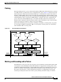
Classification 14-4
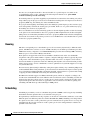
Policing 14-5
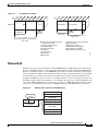
Marking and Discarding with a Policer 14-5
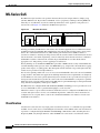
Queuing 14-6
Scheduling 14-6
Control Packets and L2 Tunneled Protocols 14-8
Egress Priority Marking 14-8
Ingress Priority Marking 14-8
QinQ Implementation 14-8
Flow Control Pause and QoS 14-9
QoS on Cisco Proprietary RPR
14-10
Configuring QoS 14-12
Creating a Traffic Class 14-12
Creating a Traffic Policy 14-13
Attaching a Traffic Policy to an Interface
Configuring CoS-Based QoS 14-17
Monitoring and Verifying QoS Configuration
14-16
14-17
QoS Configuration Examples 14-18
Traffic Classes Defined Example 14-19
Traffic Policy Created Example 14-19
class-map match-any and class-map match-all Commands Example
match spr1 Interface Example 14-20
ML-Series VoIP Example 14-21
ML-Series Policing Example 14-21
ML-Series CoS-Based QoS Example 14-22
Understanding Multicast QoS and Priority Multicast Queuing
Default Multicast QoS 14-24
Multicast Priority Queuing QoS Restrictions 14-25
Configuring Multicast Priority Queuing QoS
QoS not Configured on Egress
14-20
14-24
14-25
14-27
ML-Series Egress Bandwidth Example 14-27
Case 1: QoS with Priority and Bandwidth Configured Without Priority Multicast 14-27
Case 2: QoS with Priority and Bandwidth Configured with Priority Multicast 14-28
Understanding CoS-Based Packet Statistics
14-29
Ethernet Card Software Feature and Configuration Guide, R7.2
January 2009
ix
Contents
Configuring CoS-Based Packet Statistics
Understanding IP SLA 14-31
IP SLA on the ML-Series 14-32
IP SLA Restrictions on the ML-Series
CHAPTER
15
14-29
14-32
Configuring the Switching Database Manager
Understanding the SDM
15-1
15-1
Understanding SDM Regions
15-1
Configuring SDM 15-2
Configuring SDM Regions 15-2
Configuring Access Control List Size in TCAM
Monitoring and Verifying SDM
CHAPTER
16
Configuring Access Control Lists
Understanding ACLs
15-3
15-3
16-1
16-1
ML-Series ACL Support 16-1
IP ACLs 16-2
Named IP ACLs 16-2
User Guidelines 16-2
Creating IP ACLs 16-3
Creating Numbered Standard and Extended IP ACLs 16-3
Creating Named Standard IP ACLs 16-4
Creating Named Extended IP ACLs (Control Plane Only) 16-4
Applying the ACL to an Interface 16-4
Modifying ACL TCAM Size
CHAPTER
17
16-5
Configuring Cisco Proprietary Resilient Packet Ring
17-1
Understanding Cisco Proprietary RPR 17-2
Role of SONET/SDH Circuits 17-2
Packet Handling Operations 17-2
Ring Wrapping 17-3
Cisco Proprietary RPR Framing Process 17-5
MAC Address and VLAN Support 17-6
Cisco Proprietary RPR QoS 17-7
CTM and Cisco Proprietary RPR 17-7
Configuring Cisco Proprietary RPR 17-7
Connecting the ML-Series Cards with Point-to-Point STS/STM Circuits
Configuring CTC Circuits for Cisco Proprietary RPR 17-8
17-8
Ethernet Card Software Feature and Configuration Guide, R7.2
x
January 2009
Contents
CTC Circuit Configuration Example for Cisco Proprietary RPR 17-8
Configuring Cisco Proprietary RPR Characteristics and the SPR Interface on the ML-Series
Card 17-12
Assigning the ML-Series Card POS Ports to the SPR Interface 17-14
Creating the Bridge Group and Assigning the Ethernet and SPR Interfaces 17-15
Cisco Proprietary RPR Cisco IOS Configuration Example 17-16
Verifying Ethernet Connectivity Between Cisco Proprietary RPR Ethernet Access Ports 17-18
CRC threshold configuration and detection 17-18
Monitoring and Verifying Cisco Proprietary RPR
17-18
Add an ML-Series Card into a Cisco Proprietary RPR 17-19
Adding an ML-Series Card into a Cisco Proprietary RPR
17-22
Delete an ML-Series Card from a Cisco Proprietary RPR 17-24
Deleting an ML-Series Card from a Cisco Proprietary RPR 17-26
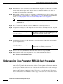
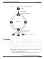
Understanding Cisco Proprietary RPR Link Fault Propagation
LFP Sequence 17-29
Propagation Delays 17-30
17-28
Configuring LFP 17-30
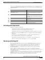
LFP Configuration Requirements 17-31
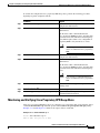
Monitoring and Verifying LFP 17-31
Cisco Proprietary RPR Keep Alive
17-32
Configuring Cisco Proprietary RPR Keep Alive 17-32
Monitoring and Verifying Cisco Proprietary RPR Keep Alives
Cisco Proprietary RPR Shortest Path
17-33
17-34
Configuring Shortest Path and Topology Discovery 17-36
Monitoring and Verifying Topology Discovery and Shortest Path Load Balancing
17-36
Understanding Redundant Interconnect 17-37
Characteristics of RI on the ML-Series Card 17-37
RI for SW RPR Configuration Example 17-38
CHAPTER
18
Configuring Ethernet over MPLS
18-1
Understanding EoMPLS 18-1
EoMPLS Support 18-3
EoMPLS Restrictions 18-3
EoMPLS Quality of Service 18-3
Configuring EoMPLS 18-4
EoMPLS Configuration Guidelines 18-5
VC Type 4 Configuration on PE-CLE Port 18-5
VC Type 5 Configuration on PE-CLE Port 18-6
Ethernet Card Software Feature and Configuration Guide, R7.2
January 2009
xi
Contents
EoMPLS Configuration on PE-CLE SPR Interface 18-8
Bridge Group Configuration on MPLS Cloud-facing Port
Setting the Priority of Packets with the EXP 18-9
EoMPLS Configuration Example
18-8
18-9
Monitoring and Verifying EoMPLS
18-12
Understanding MPLS-TE 18-13
RSVP on the ML-Series Card 18-13
Ethernet FCS Preservation 18-13
Configuring MPLS-TE 18-14
Configuring an ML-Series Card for Tunnels Support 18-14
Configuring an Interface to Support RSVP-Based Tunnel Signalling and IGP Flooding
Configuring OSPF and Refresh Reduction for MPLS-TE 18-15
Configuring an MPLS-TE Tunnel 18-15
MPLS-TE Configuration Example
18-16
Monitoring and Verifying MPLS-TE and IP RSVP
RPRW Alarm
CHAPTER
19
18-14
18-18
18-19
Configuring Security for the ML-Series Card
Understanding Security
19-1
19-1
Disabling the Console Port on the ML-Series Card
Secure Login on the ML-Series Card
19-2
19-2
Secure Shell on the ML-Series Card 19-2
Understanding SSH 19-2
Configuring SSH 19-3
Configuration Guidelines 19-3
Setting Up the ML-Series Card to Run SSH 19-3
Configuring the SSH Server 19-4
Displaying the SSH Configuration and Status 19-5
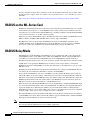
RADIUS on the ML-Series Card
19-6
RADIUS Relay Mode 19-6
Configuring RADIUS Relay Mode
19-7
RADIUS Stand Alone Mode 19-7
Understanding RADIUS 19-8
Configuring RADIUS 19-8
Default RADIUS Configuration 19-9
Identifying the RADIUS Server Host 19-9
Configuring AAA Login Authentication 19-11
Defining AAA Server Groups 19-13
Ethernet Card Software Feature and Configuration Guide, R7.2
xii
January 2009
Contents
Configuring RADIUS Authorization for User Privileged Access and Network Services 19-15
Starting RADIUS Accounting 19-16
Configuring a nas-ip-address in the RADIUS Packet 19-16
Configuring Settings for All RADIUS Servers 19-17
Configuring the ML-Series Card to Use Vendor-Specific RADIUS Attributes 19-18
Configuring the ML-Series Card for Vendor-Proprietary RADIUS Server Communication 19-19
Displaying the RADIUS Configuration 19-20
CHAPTER
20
POS on ONS Ethernet Cards
POS Overview
20-1
20-1
POS Interoperability
20-2
POS Encapsulation Types 20-4
IEEE 802.17b 20-4
LEX 20-5
PPP/BCP 20-6
Cisco HDLC 20-6
E-Series Proprietary 20-7
POS Framing Modes 20-7
HDLC Framing 20-7
GFP-F Framing 20-7
POS Characteristics of Specific ONS Ethernet Cards 20-7
ONS 15327 E-10/100-4 Framing and Encapsulation Options 20-8
ONS 15454 and ONS 15454 SDH E-Series Framing and Encapsulation Options 20-8
G-Series Encapsulation and Framing 20-9
ONS 15454, ONS 15454 SDH, ONS 15310-CL, and and ONS 15310-MA CE-Series Cards Encapsulation
and Framing 20-10
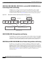
ONS 15310 ML-100T-8 Encapsulation and Framing 20-10
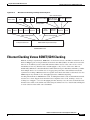
ONS 15454 and ONS 15454 SDH ML-Series Protocol Encapsulation and Framing 20-10
Ethernet Clocking Versus SONET/SDH Clocking
CHAPTER
21
Configuring RMON
20-11
21-1
Understanding RMON
21-1
Configuring RMON 21-2
Default RMON Configuration 21-2
Configuring RMON Alarms and Events 21-2
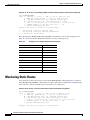
Collecting Group History Statistics on an Interface 21-5
Collecting Group Ethernet Statistics on an Interface 21-6
Understanding ML-Series Card CRC Error Threshold
Threshold and Triggered Actions 21-7
21-6
Ethernet Card Software Feature and Configuration Guide, R7.2
January 2009
xiii
Contents
SONET/GFP Suppression of CRC-ALARM
Clearing of CRC-ALARM 21-7
Unwrap Synchronization 21-8
Unidirectional Errors 21-8
Bidirectional Errors 21-10
21-7
Configuring the ML-Series Card CRC Error Threshold 21-13
Clearing the CRC-ALARM Wrap with the Clear CRC Error Command
21-14
Configuring ML-Series Card RMON for CRC Errors 21-15
Configuration Guidelines for CRC Thresholds on the ML-Series Card 21-15
Accessing CRC Errors Through SNMP 21-15
Configuring an SNMP Trap for the CRC Error Threshold Using Cisco IOS 21-16
Determining the ifIndex Number for an ML-Series Card 21-18
Manually Checking CRC Errors on the ML-Series Card 21-19
Displaying RMON Status
CHAPTER
22
Configuring SNMP
21-20
22-1
Understanding SNMP 22-1
SNMP on the ML-Series Card 22-2
SNMP Versions 22-3
SNMP Manager Functions 22-3
SNMP Agent Functions 22-4
SNMP Community Strings 22-4
Using SNMP to Access MIB Variables
Supported MIBs 22-5
SNMP Notifications 22-5
22-4
Configuring SNMP 22-6
Default SNMP Configuration 22-6
SNMP Configuration Guidelines 22-6
Disabling the SNMP Agent 22-7
Configuring Community Strings 22-7
Configuring SNMP Groups and Users 22-9
Configuring SNMP Notifications 22-10
Setting the Agent Contact and Location Information
Limiting TFTP Servers Used Through SNMP 22-13
SNMP Examples 22-13
Displaying SNMP Status
CHAPTER
23
22-14
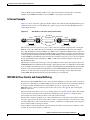
E-Series and G-Series Ethernet Operation
G-Series Application
22-12
23-1
23-1
Ethernet Card Software Feature and Configuration Guide, R7.2
xiv
January 2009
Contents
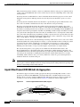
G1K-4 and G1000-4 Comparison 23-2
G-Series Example 23-3
IEEE 802.3z Flow Control and Frame Buffering 23-3
Gigabit EtherChannel/IEEE 802.3ad Link Aggregation 23-4
Ethernet Link Integrity Support 23-5
Administrative and Service States with Soak Time for Ethernet and SONET/SDH Ports
G-Series Circuit Configurations 23-6
G-Series Point-to-Point Ethernet Circuits
G-Series Manual Cross-Connects 23-7
23-6
23-6
G-Series Gigabit Ethernet Transponder Mode 23-8
Two-Port Bidirectional Transponder Mode 23-10
One-Port Bidirectional Transponder Mode 23-10
Two-Port Unidirectional Transponder Mode 23-11
G-Series Transponder Mode Characteristics 23-12
E-Series Application 23-13
E-Series Modes 23-13
E-Series Multicard EtherSwitch Group 23-14
E-Series Single-Card EtherSwitch 23-14
Port-Mapped (Linear Mapper) 23-15
Available Circuit Sizes For E-Series Modes 23-16
Available Total Bandwidth For E-Series Modes 23-16
E-Series IEEE 802.3z Flow Control 23-16
E-Series VLAN Support 23-17
E-Series Q-Tagging (IEEE 802.1Q) 23-18
E-Series Priority Queuing (IEEE 802.1Q) 23-20
E-Series Spanning Tree (IEEE 802.1D) 23-21
E-Series Multi-Instance Spanning Tree and VLANs 23-22
Spanning Tree on a Circuit-by-Circuit Basis 23-22
E-Series Spanning Tree Parameters 23-22
E-Series Spanning Tree Configuration 23-23
E-Series Circuit Configurations 23-23
E-Series Circuit Protection 23-24
E-Series Point-to-Point Ethernet Circuits 23-24
E-Series Shared Packet Ring Ethernet Circuits 23-25
E-Series Hub-and-Spoke Ethernet Circuit Provisioning
E-Series Ethernet Manual Cross-Connects 23-26
Remote Monitoring Specification Alarm Thresholds
23-26
23-26
Ethernet Card Software Feature and Configuration Guide, R7.2
January 2009
xv
Contents
CHAPTER
24
CE-100T-8 Ethernet Operation
CE-100T-8 Overview
24-1
24-1
CE-100T-8 Ethernet Features 24-2
Autonegotiation, Flow Control, and Frame Buffering 24-2
Ethernet Link Integrity Support 24-3
Administrative and Service States with Soak Time for Ethernet and SONET/SDH Ports
IEEE 802.1Q CoS and IP ToS Queuing 24-5
RMON and SNMP Support 24-6
Statistics and Counters 24-6
24-4
CE-100T-8 SONET/SDH Circuits and Features 24-7
Available Circuit Sizes and Combinations 24-7
CE-100T-8 Pools 24-11
Displaying CE-100T-8 Pool Information with the STS/VT Allocation or VC4/VC LO Allocation
Tab 24-11
CE-100T-8 Pool Allocation Example 24-13
CE-100T-8 Pool Provisioning Rules 24-14
CE-100T-8 VCAT Characteristics 24-14
CE-100T-8 POS Encapsulation, Framing, and CRC 24-14
CE-100T-8 Loopback, J1 Path Trace, and SONET/SDH Alarms 24-15
CHAPTER
25
CE-1000-4 Ethernet Operation
CE-1000-4 Overview
25-1
25-1
CE-1000-4 Ethernet Features 25-2
Autonegotiation and Frame Buffering 25-3
Flow Control 25-3
Flow Control Threshold Provisioning 25-4
Ethernet Link Integrity Support 25-4
Administrative and Service States with Soak Time for Ethernet and SONET/SDH Ports
RMON and SNMP Support 25-5
Statistics and Counters 25-6
CE-1000-4 SONET/SDH Circuits and Features 25-6
CE-1000-4 VCAT Characteristics 25-6
CE-1000-4 POS Encapsulation, Framing, and CRC 25-7
CE-1000-4 Loopback, J1 Path Trace, and SONET/SDH Alarms
CHAPTER
26
Configuring IEEE 802.17b Resilient Packet Ring
Understanding RPR-IEEE 26-1
RPR-IEEE Features on the ML-Series Card
Advantages of RPR-IEEE 26-2
25-5
25-8
26-1
26-2
Ethernet Card Software Feature and Configuration Guide, R7.2
xvi
January 2009
Contents
Role of SONET/SDH Circuits 26-2
RPR-IEEE Framing Process 26-3
CTM and RPR-IEEE 26-6
Configuring RPR-IEEE Characteristics 26-6
Configuring the Attribute Discovery Timer 26-7
Configuring the Reporting of SONET Alarms 26-7
Configuring BER Threshold Values 26-8
Configuring RPR-IEEE Protection 26-8
Configuring the Hold-off Timer 26-9
Configuring Jumbo Frames 26-10
Configuring Forced or Manual Switching 26-11
Configuring Protection Timers 26-12
Configuring the Wait-to-Restore Timer 26-13
Configuring a Span Shutdown 26-14
Configuring Keepalive Events 26-14
Configuring Triggers for CRC Errors 26-15
Configuring QoS on RPR-IEEE 26-17
Class A 26-17
ClassB 26-17
ClassC 26-18
MQC -IEEE RPR CLI Characteristics 26-18
Configuring Traffic Rates for Transmission 26-18
Configuring Fairness Weights 26-19
Configuring RPR-IEEE Service Classes Using the Modular QoS CLI
26-19
Configuration Example for RPR-IEEE QoS 26-21
Configuration Example Using MQC to Configure Simple RPR-IEEE QoS 26-21
Configuration Example Using MQC to Configure Complex RPR-IEEE QoS 26-21
Verifying and Monitoring RPR-IEEE
26-22
Configuring RPR-IEEE End-to-End 26-30
Provisioning Card Mode 26-31
Connecting the ML-Series Cards with Point-to-Point STS/STM Circuits 26-31
Guidelines for Connecting the ML-Series Cards with Point-to-Point STS/STM Circuits 26-31
Example of Connecting the ML-Series Cards with Point-to-Point STS/STM Circuits 26-32
Creating the RPR-IEEE Interface and Bridge Group 26-32
Understanding the RPR-IEEE Interface 26-33
Understanding the RPR-IEEE Bridge Group 26-33
Configuration Examples for Cisco IOS CLI Portion of End-to-End RPR-IEEE 26-35
Verifying RPR-IEEE End-to-End Ethernet Connectivity 26-37
Understanding Redundant Interconnect
26-37
Ethernet Card Software Feature and Configuration Guide, R7.2
January 2009
xvii
Contents
Characteristics of RI on the ML-Series Card
RI Configuration Example 26-39
APPENDIX
A
Command Reference
APPENDIX
B
Unsupported CLI Commands
26-38
A-1
B-1
Unsupported Privileged Exec Commands
B-1
Unsupported Global Configuration Commands
B-1
Unsupported POS Interface Configuration Commands
B-3
Unsupported POS Interface Configuration Commands (Cisco Proprietary RPR Virtual Interface)
Unsupported IEEE 802.17 RPR Interface Configuration Commands
B-4
Unsupported FastEthernet or GigabitEthernet Interface Configuration Commands
Unsupported Port-Channel Interface Configuration Commands
Unsupported BVI Interface Configuration Commands
APPENDIX
C
Using Technical Support
B-4
B-5
B-6
B-7
C-1
Gathering Information About Your Internetwork
Getting the Data from Your ML-Series Card
C-1
C-2
Providing Data to Your Technical Support Representative
C-3
INDEX
Ethernet Card Software Feature and Configuration Guide, R7.2
xviii
January 2009
F I G U R E S
Figure 3-1
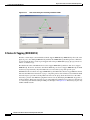
CTC IOS Window
Figure 3-2
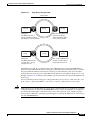
CTC Node View Showing IP Address and Slot Number
Figure 3-3
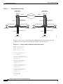
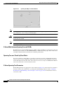
Console Cable Adapter
Figure 3-4
Connecting to the Console Port
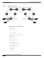
Figure 5-1
ML-Series Card to ML-Series Card POS Configuration
Figure 5-2
ML-Series Card to Cisco 12000 Series Gigabit Switch Router (GSR) POS Configuration
Figure 5-3
ML-Series Card to G-Series Card POS Configuration
Figure 5-4
ML-Series Card to ONS 15310 CE-100T-8 Card Configuration
Figure 6-1
Bridging Example
Figure 7-1
Spanning-Tree Topology
Figure 7-2
Spanning-Tree Interface States
Figure 7-3
Spanning Tree and Redundant Connectivity
Figure 7-4
Proposal and Agreement Handshaking for Rapid Convergence
Figure 7-5
Sequence of Events During Rapid Convergence
Figure 8-1
VLANs Spanning Devices in a Network
Figure 8-2
Bridging IEEE 802.1Q VLANs
Figure 9-1
IEEE 802.1Q Tunnel Ports in a Service-Provider Network
Figure 9-2
Normal, IEEE 802.1Q, and IEEE 802.1Q-Tunneled Ethernet Packet Formats
Figure 9-3
ERMS Example
Figure 10-1
EtherChannel Example
10-3
Figure 10-2
POS Channel Example
10-6
Figure 10-3
Encapsulation over EtherChannel Example
Figure 11-1
IP Routing Protocol Example Using OSPF
Figure 12-1
Configuring IRB
Figure 13-1
VRF Lite—Sample Network Scenario
Figure 14-1
IP Precedence and DSCP
Figure 14-2
Ethernet Frame and the CoS Bit (IEEE 802.1p)
Figure 14-3
ML-Series QoS Flow
Figure 14-4
Dual Leaky Bucket Policer Model
Figure 14-5
Queuing and Scheduling Model
Figure 14-6
QinQ
3-3
3-4
3-5
3-6
5-11
5-12
5-14
5-14
6-3
7-5
7-6
7-8
7-12
7-13
8-2
8-4
9-2
9-3
9-7
10-8
11-11
12-3
13-3
14-3
14-3
14-4
14-5
14-7
14-9
Ethernet Card Software Feature and Configuration Guide, R7.2
January 2009
xix
Figures
Figure 14-7
ML-Series VoIP Example
Figure 14-8
ML-Series Policing Example
Figure 14-9
ML-Series CoS Example
Figure 14-10
QoS not Configured on Egress
Figure 17-1
Cisco Proprietary RPR Packet Handling Operations
Figure 17-2
Cisco proprietary RPR Ring Wrapping
Figure 17-3
Cisco Proprietary RPR Frame for ML-Series Card
Figure 17-4
Cisco Proprietary RPR Frame Fields
Figure 17-5
Three Node Cisco Proprietary RPR
17-9
Figure 17-6
CTC Card View for ML-Series Card
17-10
Figure 17-7
CTC Circuit Creation Wizard
Figure 17-8
Cisco proprietary RPR Bridge Group
Figure 17-9
Two-Node Cisco Proprietary RPR Before the Addition
17-20
Figure 17-10
Three Node Cisco Proprietary RPR After the Addition
17-21
Figure 17-11
Three Node Cisco Proprietary RPR Before the Deletion
Figure 17-12
Two Node Cisco Proprietary RPR After the Deletion
Figure 17-13
Cisco Proprietary RPR Link Fault Propagation Example
Figure 17-14
Shortest and Longest Path
Figure 17-15
RPR RI
Figure 18-1
EoMPLS Service Provider Network
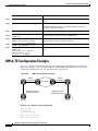
Figure 18-2
EoMPLS Configuration Example
Figure 18-3
MPLS-TE Configuration Example
Figure 20-1
Ethernet to POS Process on ONS Node
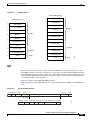
Figure 20-2
RPR Data Frames
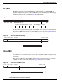
Figure 20-3
LEX Under HDLC Framing
20-5
Figure 20-4
BCP Under HDLC Framing
20-6
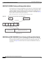
Figure 20-5
PPP Frame Under HDLC Framing
Figure 20-6
Cisco HDLC Under HDLC Framing
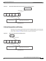
Figure 20-7
ONS 15327 E-Series Encapsulation and Framing Options
Figure 20-8
ONS 15454 and ONS 15454 SDH E-Series Encapsulation and Framing Options
Figure 20-9
ONS G-Series Encapsulation and Framing Options
Figure 20-10
ONS CE-100T-8 and ONS CE-1000-4 Encapsulation and Framing Options
Figure 20-11
ML-Series Card Framing and Encapsulation Options
Figure 21-1
Remote Monitoring Example
Figure 21-2
Wrapped Cisco proprietary RPR with Unidirectional Excessive CRC Errors
14-21
14-22
14-23
14-27
17-3
17-4
17-5
17-6
17-10
17-16
17-25
17-25
17-29
17-35
17-37
18-2
18-10
18-16
20-2
20-5
20-6
20-6
20-8
20-9
20-9
20-10
20-11
21-2
21-9
Ethernet Card Software Feature and Configuration Guide, R7.2
xx
January 2009
Figures
Figure 21-3
Unwrapped Cisco proprietary RPR with Unidirectional Excessive CRC Errors
Figure 21-4
Wrapped Cisco proprietary RPR with Bidirectional Excessive CRC Errors
Figure 21-5
First Stage of Unwrapped Cisco proprietary RPR with Bidirectional Excessive CRC Errors
Figure 21-6
Second Stage of Unwrapped Cisco proprietary RPR with Bidirectional Excessive CRC Errors
Figure 22-1
SNMP on the ML-Series Card Example
Figure 22-2
SNMP Network
Figure 23-1
Data Traffic on a G-Series Point-to-Point Circuit
Figure 23-2
G-Series Gigabit EtherChannel (GEC) Support
Figure 23-3
End-to-End Ethernet Link Integrity Support
Figure 23-4
G-Series Point-to-Point Circuit
Figure 23-5
G-Series Manual Cross-Connects
Figure 23-6
Card Level Overview of G-Series One-Port Transponder Mode Application
Figure 23-7
G-Series in Default SONET/SDH Mode
Figure 23-8
G-Series Card in Transponder Mode (Two-Port Bidirectional)
Figure 23-9
One-Port Bidirectional Transponder Mode
Figure 23-10
Two-Port Unidirectional Transponder
23-12
Figure 23-11
Multicard EtherSwitch Configuration
23-14
Figure 23-12
Single-Card EtherSwitch Configuration
Figure 23-13
E-Series Mapping Ethernet Ports to STS/VC Circuits
Figure 23-14
Edit Circuit Dialog Box Featuring Available VLANs
Figure 23-15
Q-tag Moving Through VLAN
Figure 23-16
Priority Queuing Process
Figure 23-17
STP Blocked Path
Figure 23-18
Spanning Tree Map on Circuit Window
Figure 23-19
Multicard EtherSwitch Point-to-Point Circuit
Figure 23-20
Single-Card EtherSwitch or Port-Mapped Point-to-Point Circuit
Figure 23-21
Shared Packet Ring Ethernet Circuit
Figure 23-22
Hub-and-Spoke Ethernet Circuit
23-26
Figure 24-1
CE-100T-8 Point-to-Point Circuit
24-1
Figure 24-2
Flow Control
Figure 24-3
End-to-End Ethernet Link Integrity Support
Figure 24-4
CE-100T-8 Allocation Tab for SDH
24-12
Figure 24-5
CE-100T-8 STS/VT Allocation Tab
24-13
Figure 25-1
CE-1000-4 Point-to-Point Circuit
Figure 25-2
Flow Control
21-10
21-11
21-12
21-13
22-2
22-4
23-3
23-4
23-5
23-7
23-8
23-8
23-9
23-9
23-11
23-15
23-15
23-18
23-19
23-20
23-21
23-22
23-24
23-25
23-25
24-3
24-3
25-2
25-3
Ethernet Card Software Feature and Configuration Guide, R7.2
January 2009
xxi
Figures
Figure 25-3
End-to-End Ethernet Link Integrity Support
Figure 26-1
Dual-Ring Structure
Figure 26-2
RPR-IEEE Data Frames
Figure 26-3
Topology and Protection Control Frame Formats
Figure 26-4
Fairness Frame Format
Figure 26-5
Each RPR-IEEE Node Responding to a Protection Event by Steering
Figure 26-6
Three Node RPR-IEEE Example
Figure 26-7
RPR-IEEE Bridge Group
Figure 26-8
RPR RI
25-4
26-3
26-4
26-5
26-6
26-9
26-32
26-33
26-38
Ethernet Card Software Feature and Configuration Guide, R7.2
xxii
January 2009
T A B L E S
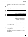
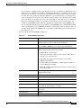
Table 2-1
ML-Series POS and Ethernet Statistics Fields and Buttons
Table 2-2
CTC Display of Ethernet Port Provisioning Status
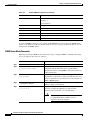
Table 2-3
CTC Display of POS Port Provisioning Status
Table 3-1
RJ-11 to RJ-45 Pin Mapping
Table 3-2
Microcode Image Feature Comparison
Table 3-3
Cisco IOS Command Modes
Table 5-1
SONET STS Circuit Capacity in Line Rate Mbps
Table 5-2
VCAT Circuit Sizes Supported by ML100T-12, ML100X-8, and ML1000-2 Cards
Table 5-3
Supported Encapsulation, Framing, and CRC Sizes for ML-Series Cards on the ONS 15454 and ONS 15454
SDH 5-4
Table 5-4
Default MTU Size
Table 5-5
C2 Byte and Scrambling Default Values
Table 5-6
ML-Series Parameter Configuration for Connection to a Cisco 12000 GSR-Series Router
Table 7-1
Switch Priority Value and Extended System ID
Table 7-2
Spanning-Tree Timers
7-4
Table 7-3
Port State Comparison
7-10
Table 7-4
RSTP BPDU Flags
Table 7-5
Default STP and RSTP Configuration
Table 7-6
Commands for Displaying Spanning-Tree Status
Table 9-1
VLAN-Transparent Service Versus VLAN-Specific Services
Table 9-2
Default Layer 2 Protocol Tunneling Configuration
Table 9-3
Commands for Monitoring and Maintaining Tunneling
Table 11-1
Default RIP Configuration
Table 11-2
Default OSPF Configuration
Table 11-3
Show IP OSPF Statistics Commands
Table 11-4
Default EIGRP Configuration
Table 11-5
IP EIGRP Clear and Show Commands
Table 11-6
BGP Show Commands
11-28
Table 11-7
IS-IS Show Commands
11-30
Table 11-8
Routing Protocol Default Administrative Distances
Table 11-9
Commands to Clear IP Routes or Display Route Status
Table 11-10
IP Multicast Routing Show Commands
2-2
2-2
2-3
3-5
3-12
3-14
5-2
5-3
5-6
5-8
5-13
7-4
7-13
7-16
7-20
9-6
9-11
9-13
11-5
11-10
11-19
11-21
11-26
11-32
11-33
11-35
Ethernet Card Software Feature and Configuration Guide, R7.2
January 2009
xxiii
Tables
Table 12-1
Commands for Monitoring and Verifying IRB
Table 12-2
show interfaces irb Field Descriptions
Table 13-1
Commands for Monitoring and Verifying VRF Lite
Table 14-1
Traffic Class Commands
14-12
Table 14-2
Traffic Policy Commands
14-14
Table 14-3
CoS Commit Command
Table 14-4
Commands for QoS Status
Table 14-5
CoS Multicast Priority Queuing Command
Table 14-6
Packet Statistics on ML-Series Card Interfaces
Table 14-7
CoS-Based Packet Statistics Command
Table 14-8
Commands for CoS-Based Packet Statistics
Table 15-1
Default Partitioning by Application Region
Table 15-2
Partitioning the TCAM Size for ACLs
Table 16-1
Commands for Numbered Standard and Extended IP ACLs
Table 16-2
Applying ACL to Interface
Table 17-1
Definitions of RPR Frame Fields
Table 18-1
Applicable EoMPLS QoS Statements and Actions
Table 18-2
Commands for Monitoring and Maintaining Tunneling
Table 18-3
Commands for Monitoring and Verifying MPLS-TE
Table 18-4
Commands for Monitoring and Verifying IP RSVP
Table 19-1
Commands for Displaying the SSH Server Configuration and Status
Table 20-1
ONS SONET/SDH Ethernet Card Interoperability under HDLC Framing with Encapsulation Type and CRC
Table 20-2
ONS SONET/SDH Ethernet Card Interoperability under GFP-F Framing with Encapsulation Type
Table 21-1
Port Numbers for the Interfaces of ML-Series Cards
21-18
Table 21-2
Port Numbers for the Interfaces of ML-Series Cards
21-19
Table 21-3
Commands for Displaying RMON Status
Table 22-1
SNMP Operations
Table 22-2
Default SNMP Configuration
Table 22-3
ML-Series Card Notification Types
Table 22-4
Commands for Displaying SNMP Information
Table 23-1
ONS 15454 and ONS 15327 E-Series Ethernet Circuit Sizes
Table 23-2
ONS 15454 and ONS 15327 E-Series Total Bandwidth Available
Table 23-3
Priority Queuing
Table 23-4
Spanning Tree Parameters
Table 23-5
Spanning Tree Configuration
12-5
12-6
13-7
14-17
14-18
14-26
14-29
14-30
14-30
15-2
15-3
16-3
16-5
17-6
18-4
18-12
18-18
18-19
19-5
20-3
20-4
21-20
22-3
22-6
22-10
22-14
23-16
23-16
23-20
23-23
23-23
Ethernet Card Software Feature and Configuration Guide, R7.2
xxiv
January 2009
Tables
Table 23-6
Protection for E-Series Circuit Configurations
Table 24-1
IP ToS Priority Queue Mappings
Table 24-2
CoS Priority Queue Mappings
Table 24-3
Supported SONET Circuit Sizes of CE-100T-8 on ONS 15454
Table 24-4
CE-100T-8 Supported SDH Circuit Sizes of CE-100T-8 on ONS 15454 SDH
Table 24-5
Minimum SONET Circuit Sizes for Ethernet Speeds
Table 24-6
SDH Circuit Sizes and Ethernet Services
Table 24-7
CCAT High-Order Circuit Size Combinations for SONET
Table 24-8
CCAT High-Order Circuit Size Combinations for SDH
Table 24-9
VCAT High-Order Circuit Combinations for STS-1-3v and STS-1-2v SONET
Table 24-10
VCAT Circuit Combinations for VC-3-3v and VC-3-2v for SDH
Table 24-11
CE-100T-8 Illustrative Service Densities for SONET
Table 24-12
CE-100T-8 Sample Service Densities for SDH
Table 26-1
Definitions of RPR-IEEE Frame Fields
23-24
24-5
24-5
24-7
24-7
24-7
24-8
24-8
24-8
24-8
24-9
24-9
24-10
26-4
Ethernet Card Software Feature and Configuration Guide, R7.2
January 2009
xxv
Tables
Ethernet Card Software Feature and Configuration Guide, R7.2
xxvi
January 2009
About this Guide
Note
The terms "Unidirectional Path Switched Ring" and "UPSR" may appear in Cisco literature. These terms
do not refer to using Cisco ONS 15xxx products in a unidirectional path switched ring configuration.
Rather, these terms, as well as "Path Protected Mesh Network" and "PPMN," refer generally to Cisco's
path protection feature, which may be used in any topological network configuration. Cisco does not
recommend using its path protection feature in any particular topological network configuration.
This section explains the objectives, intended audience, and organization of this publication and
describes the conventions that convey instructions and other information.
This section provides the following information:
•
Revision History
•
Document Objectives
•
Audience
•
Document Organization
•
Related Documentation
•
Document Conventions
•
Obtaining Optical Networking Information
•
Obtaining Documentation and Submitting a Service Request
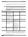
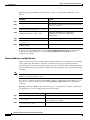
Revision History
Date
Notes
March 2007
Revision History table added.
April 2007
Added server trail information to the “CE-100T-8 VCAT Characteristics” section
in the “CE-100T-8 Ethernet Operation” chapter and the “CE-1000-4 VCAT
Characteristics” section in the “CE-1000-4 Ethernet Operation” chapter.
August 2007
Updated About this Guide chapter.
October 2007
Updated Appendix A, Command Reference with the rpr-ieee tx-traffic
preferred-span command.
Ethernet Card Software Feature and Configuration Guide, R7.2
January 2009
xxvii
About this Guide
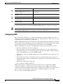
Date
Notes
July 2008
Updated section “Flow Control Pause and QoS” of the Ingress Priority Marking
Topic in Chapter 14, Configuring Quality of Service.
January 2009
Added the following sections in Chapter 14, Configuring Quality of Service:
•
QoS not Configured on Egress
•
ML-Series Egress Bandwidth Example
•
Added a new bullet point in the “IP SLA Restrictions on the ML-Series”
section.
Document Objectives
This guide covers the software features and operations of Ethernet cards for the Cisco ONS 15454,
Cisco ONS 15454 SDH, and Cisco ONS 15327. It explains software features and configuration for
Cisco IOS on the ML-Series card. The ML-Series card is a module in the Cisco ONS 15454 SONET or
Cisco ONS 15454 SDH system. It also explains software feature and configuration for CTC on the
E-Series, G-Series and CE-Series cards. The E-Series cards and G-Series cards are modules in the
Cisco ONS 15454, Cisco ONS 15454 SDH, and Cisco ONS 15327. The CE-Series cards are modules in
the Cisco ONS 15454. The CE-100T-8 is also available as module for the Cisco ONS 15310-CL. The
Cisco ONS 15310-CL version of the card is covered in the Cisco ONS 15310-CL and
Cisco ONS 15310-MA Ethernet Card Software Feature and Configuration Guide. Use this guide in
conjunction with the appropriate publications listed in the Related Documentation section.
Audience
To use the ML-Series card chapters of this publication, you should be familiar with Cisco IOS and
preferably have technical networking background and experience. To use the E-Series, G-Series and
CE-Series card chapters of this publication, you should be familiar with CTC and preferably have
technical networking background and experience.
Document Organization
The Ethernet Card Software Feature and Configuration Guide, R7.2 is organized into the following
chapters:
•
Chapter 1, “ML-Series Card Overview,” provides a description of the ML-Series card, a feature list,
and explanations of key features.
•
Chapter 2, “CTC Operations,”provides details and procedures for using Cisco Transport Controller
(CTC) software with the ML-Series card.
•
Chapter 3, “Initial Configuration,” provides procedures to access the ML-Series card and create and
manage startup configuration files.
•
Chapter 4, “Configuring Interfaces,” provides information on the ML-Series card interfaces and
basic procedures for the interfaces.
•
Chapter 5, “Configuring POS,” provides information on the ML-Series card POS interfaces and
advanced procedures for the POS interfaces.
Ethernet Card Software Feature and Configuration Guide, R7.2
xxviii
January 2009
About this Guide
•
Chapter 6, “Configuring Bridges,” provides bridging examples and procedures for the ML-Series
card.
•
Chapter 7, “Configuring STP and RSTP,” provides spanning tree and rapid spanning tree examples
and procedures for the ML-Series card.
•
Chapter 8, “Configuring VLANs,” provides VLAN examples and procedures for the ML-Series
card.
•
Chapter 9, “Configuring IEEE 802.1Q Tunneling and Layer 2 Protocol Tunneling,” provides
tunneling examples and procedures for the ML-Series card.
•
Chapter 10, “Configuring Link Aggregation,” provides Etherchannel and packet-over-SONET/SDH
(POS) channel examples and procedures for the ML-Series card.
•
Chapter 11, “Configuring Networking Protocols,” provides network protocol examples and
procedures for the ML-Series card.
•
Chapter 12, “Configuring IRB,” provides integrated routing and bridging (IRB) examples and
procedures for the ML-Series card.
•
Chapter 13, “Configuring VRF Lite,” provides VPN Routing and Forwarding Lite (VRF Lite)
examples and procedures for the ML-Series card.
•
Chapter 14, “Configuring Quality of Service,” provides quality of service (QoS) examples and
procedures for the ML-Series card.
•
Chapter 15, “Configuring the Switching Database Manager,” provides switching database manager
examples and procedures for the ML-Series card.
•
Chapter 16, “Configuring Access Control Lists,” provides access control list (ACL) examples and
procedures for the ML-Series card.
•
Chapter 17, “Configuring Cisco Proprietary Resilient Packet Ring,” provides resilient packet ring
(RPR) examples and procedures for the ML-Series card.
•
Chapter 18, “Configuring Ethernet over MPLS,” provides Ethernet over Multiprotocol Label
Switching (EoMPLS) examples and procedures for the ML-Series card.
•
Chapter 19, “Configuring Security for the ML-Series Card,” describes the security features of the
ML-Series card.
•
Chapter 20, “POS on ONS Ethernet Cards,” details and explains POS on Ethernet cards. It also
details Ethernet card interoperability.
•
Chapter 21, “Configuring RMON,” describes how to configure remote network monitoring (RMON)
on the ML-Series card.
•
Chapter 22, “Configuring SNMP,” describes how to configure the ML-Series card for operating with
Simple Network Management Protocol (SNMP).
•
Chapter 23, “E-Series and G-Series Ethernet Operation,” details and explains the features and
operation of E-Series and G-Series Ethernet cards for the ONS 15454, ONS 15454 SDH and
ONS 15327 platform.
•
Chapter 24, “CE-100T-8 Ethernet Operation,” details and explains the features and operation of
CE-100T-8 Ethernet card .
•
Chapter 25, “CE-1000-4 Ethernet Operation,” describes the operation of the CE-1000-4 card.
•
Appendix A, “Command Reference,” is an alphabetical listing of unique ML-Series card Cisco IOS
commands with definitions and examples.
•
Appendix B, “Unsupported CLI Commands,” is a categorized and alphabetized listing of Cisco IOS
commands that the ML-Series card does not support.
Ethernet Card Software Feature and Configuration Guide, R7.2
January 2009
xxix
About this Guide
•
Appendix C, “Using Technical Support,” instructs the user on using the Cisco Technical Assistance
Center (Cisco TAC) for ML-Series card problems.
Related Documentation
Use the Ethernet Card Software Feature and Configuration Guide, R7.2 in conjunction with the
following general ONS 15454 or ONS 15454 SDH system publications:
•
Cisco ONS 15454 Procedure Guide
Provides procedures to install, turn up, provision, and maintain a Cisco ONS 15454 node and
network.
•
Cisco ONS 15454 SDH Procedure Guide
Provides procedures to install, turn up, provision, and maintain a Cisco ONS 15454 SDH node and
network.
•
Cisco ONS 15454 Reference Manual
Provides detailed card specifications, hardware and software feature descriptions, network topology
information, and network element defaults.
•
Cisco ONS 15454 SDH Reference Manual
Provides detailed card specifications, hardware and software feature descriptions, network topology
information, and network element defaults.
•
Cisco ONS 15454 Troubleshooting Guide
Provides alarm descriptions, alarm and general troubleshooting procedures, error messages, and
performance monitoring and SNMP parameters.
•
Cisco ONS 15454 SDH Troubleshooting Guide
Provides general troubleshooting procedures, alarm descriptions and troubleshooting procedures,
error messages, and performance monitoring and SNMP parameters.
•
Cisco ONS SONET TL1 Command Guide
Provides a full TL1 command and autonomous message set including parameters, AIDs, conditions,
and modifiers for the Cisco ONS 15454, ONS 15327, ONS 15600, ONS 15310-CL, and ONS
15310-MA systems.
•
Cisco ONS 15454 SDH TL1 Command Guide
Provides a full TL1 command and autonomous message set including parameters, AIDs, conditions
and modifiers for the Cisco ONS 15454 SDH.
•
Cisco ONS SONET TL1 Reference Guide
Provides general information and procedures for TL1 in the Cisco ONS 15454, ONS 15327, ONS
15600, ONS 15310-CL, and Cisco ONS 15310-MA systems.
•
Cisco ONS 15454 SDH TL1 Reference Guide
Provides general information and procedures for TL1 in the Cisco ONS 15454 SDH.
•
Cisco ONS 15454 SDH TL1 Reference Guide
Provides general information, procedures, and errors for TL1 in the Cisco ONS 15454 SDH.
•
Release Notes for the Cisco ONS 15454 Release 7.0
Provides caveats, closed issues, and new feature and functionality information.
•
Release Notes for the Cisco ONS 15454 SDH Release 7.0
Provides caveats, closed issues, and new feature and functionality information.
•
Release Notes for the Cisco ONS 15327 Release 7.0
Provides caveats, closed issues, and new feature and functionality information.
Ethernet Card Software Feature and Configuration Guide, R7.2
xxx
January 2009
About this Guide
The ML-Series card employs the Cisco IOS Modular QoS CLI (MQC). For more information on general
MQC configuration, refer to the following Cisco IOS documents:
•
Cisco IOS Quality of Service Solutions Configuration Guide, Release 12.2
•
Cisco IOS Quality of Service Solutions Command Reference, Release 12.2
The ML-Series card employs Cisco IOS 12.2. For more general information on Cisco IOS 12.2, refer to
the extensive Cisco IOS documentation at:
•
http://www.cisco.com/
Document Conventions
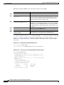
This publication uses the following conventions:
Convention
Application
boldface
Commands and keywords in body text.
italic
Command input that is supplied by the user.
[
Keywords or arguments that appear within square brackets are optional.
]
{x|x|x}
A choice of keywords (represented by x) appears in braces separated by
vertical bars. The user must select one.
Ctrl
The control key. For example, where Ctrl + D is written, hold down the
Control key while pressing the D key.
screen font
Examples of information displayed on the screen.
boldface screen font
Examples of information that the user must enter.
<
Command parameters that must be replaced by module-specific codes.
>
Note
Means reader take note. Notes contain helpful suggestions or references to material not covered in the
document.
Caution
Means reader be careful. In this situation, the user might do something that could result in equipment
damage or loss of data.
Ethernet Card Software Feature and Configuration Guide, R7.2
January 2009
xxxi
About this Guide
Warning
IMPORTANT SAFETY INSTRUCTIONS
This warning symbol means danger. You are in a situation that could cause bodily injury. Before you
work on any equipment, be aware of the hazards involved with electrical circuitry and be familiar
with standard practices for preventing accidents. Use the statement number provided at the end of
each warning to locate its translation in the translated safety warnings that accompanied this
device. Statement 1071
SAVE THESE INSTRUCTIONS
Waarschuwing
BELANGRIJKE VEILIGHEIDSINSTRUCTIES
Dit waarschuwingssymbool betekent gevaar. U verkeert in een situatie die lichamelijk letsel kan
veroorzaken. Voordat u aan enige apparatuur gaat werken, dient u zich bewust te zijn van de bij
elektrische schakelingen betrokken risico's en dient u op de hoogte te zijn van de standaard
praktijken om ongelukken te voorkomen. Gebruik het nummer van de verklaring onderaan de
waarschuwing als u een vertaling van de waarschuwing die bij het apparaat wordt geleverd, wilt
raadplegen.
BEWAAR DEZE INSTRUCTIES
Varoitus
TÄRKEITÄ TURVALLISUUSOHJEITA
Tämä varoitusmerkki merkitsee vaaraa. Tilanne voi aiheuttaa ruumiillisia vammoja. Ennen kuin
käsittelet laitteistoa, huomioi sähköpiirien käsittelemiseen liittyvät riskit ja tutustu
onnettomuuksien yleisiin ehkäisytapoihin. Turvallisuusvaroitusten käännökset löytyvät laitteen
mukana toimitettujen käännettyjen turvallisuusvaroitusten joukosta varoitusten lopussa näkyvien
lausuntonumeroiden avulla.
SÄILYTÄ NÄMÄ OHJEET
Attention
IMPORTANTES INFORMATIONS DE SÉCURITÉ
Ce symbole d'avertissement indique un danger. Vous vous trouvez dans une situation pouvant
entraîner des blessures ou des dommages corporels. Avant de travailler sur un équipement, soyez
conscient des dangers liés aux circuits électriques et familiarisez-vous avec les procédures
couramment utilisées pour éviter les accidents. Pour prendre connaissance des traductions des
avertissements figurant dans les consignes de sécurité traduites qui accompagnent cet appareil,
référez-vous au numéro de l'instruction situé à la fin de chaque avertissement.
CONSERVEZ CES INFORMATIONS
Warnung
WICHTIGE SICHERHEITSHINWEISE
Dieses Warnsymbol bedeutet Gefahr. Sie befinden sich in einer Situation, die zu Verletzungen führen
kann. Machen Sie sich vor der Arbeit mit Geräten mit den Gefahren elektrischer Schaltungen und
den üblichen Verfahren zur Vorbeugung vor Unfällen vertraut. Suchen Sie mit der am Ende jeder
Warnung angegebenen Anweisungsnummer nach der jeweiligen Übersetzung in den übersetzten
Sicherheitshinweisen, die zusammen mit diesem Gerät ausgeliefert wurden.
BEWAHREN SIE DIESE HINWEISE GUT AUF.
Ethernet Card Software Feature and Configuration Guide, R7.2
xxxii
January 2009
About this Guide
Avvertenza
IMPORTANTI ISTRUZIONI SULLA SICUREZZA
Questo simbolo di avvertenza indica un pericolo. La situazione potrebbe causare infortuni alle
persone. Prima di intervenire su qualsiasi apparecchiatura, occorre essere al corrente dei pericoli
relativi ai circuiti elettrici e conoscere le procedure standard per la prevenzione di incidenti.
Utilizzare il numero di istruzione presente alla fine di ciascuna avvertenza per individuare le
traduzioni delle avvertenze riportate in questo documento.
CONSERVARE QUESTE ISTRUZIONI
Advarsel
VIKTIGE SIKKERHETSINSTRUKSJONER
Dette advarselssymbolet betyr fare. Du er i en situasjon som kan føre til skade på person. Før du
begynner å arbeide med noe av utstyret, må du være oppmerksom på farene forbundet med
elektriske kretser, og kjenne til standardprosedyrer for å forhindre ulykker. Bruk nummeret i slutten
av hver advarsel for å finne oversettelsen i de oversatte sikkerhetsadvarslene som fulgte med denne
enheten.
TA VARE PÅ DISSE INSTRUKSJONENE
Aviso
INSTRUÇÕES IMPORTANTES DE SEGURANÇA
Este símbolo de aviso significa perigo. Você está em uma situação que poderá ser causadora de
lesões corporais. Antes de iniciar a utilização de qualquer equipamento, tenha conhecimento dos
perigos envolvidos no manuseio de circuitos elétricos e familiarize-se com as práticas habituais de
prevenção de acidentes. Utilize o número da instrução fornecido ao final de cada aviso para
localizar sua tradução nos avisos de segurança traduzidos que acompanham este dispositivo.
GUARDE ESTAS INSTRUÇÕES
¡Advertencia!
INSTRUCCIONES IMPORTANTES DE SEGURIDAD
Este símbolo de aviso indica peligro. Existe riesgo para su integridad física. Antes de manipular
cualquier equipo, considere los riesgos de la corriente eléctrica y familiarícese con los
procedimientos estándar de prevención de accidentes. Al final de cada advertencia encontrará el
número que le ayudará a encontrar el texto traducido en el apartado de traducciones que acompaña
a este dispositivo.
GUARDE ESTAS INSTRUCCIONES
Varning!
VIKTIGA SÄKERHETSANVISNINGAR
Denna varningssignal signalerar fara. Du befinner dig i en situation som kan leda till personskada.
Innan du utför arbete på någon utrustning måste du vara medveten om farorna med elkretsar och
känna till vanliga förfaranden för att förebygga olyckor. Använd det nummer som finns i slutet av
varje varning för att hitta dess översättning i de översatta säkerhetsvarningar som medföljer denna
anordning.
SPARA DESSA ANVISNINGAR
Ethernet Card Software Feature and Configuration Guide, R7.2
January 2009
xxxiii
About this Guide
Ethernet Card Software Feature and Configuration Guide, R7.2
xxxiv
January 2009
About this Guide
Aviso
INSTRUÇÕES IMPORTANTES DE SEGURANÇA
Este símbolo de aviso significa perigo. Você se encontra em uma situação em que há risco de lesões
corporais. Antes de trabalhar com qualquer equipamento, esteja ciente dos riscos que envolvem os
circuitos elétricos e familiarize-se com as práticas padrão de prevenção de acidentes. Use o
número da declaração fornecido ao final de cada aviso para localizar sua tradução nos avisos de
segurança traduzidos que acompanham o dispositivo.
GUARDE ESTAS INSTRUÇÕES
Advarsel
VIGTIGE SIKKERHEDSANVISNINGER
Dette advarselssymbol betyder fare. Du befinder dig i en situation med risiko for
legemesbeskadigelse. Før du begynder arbejde på udstyr, skal du være opmærksom på de
involverede risici, der er ved elektriske kredsløb, og du skal sætte dig ind i standardprocedurer til
undgåelse af ulykker. Brug erklæringsnummeret efter hver advarsel for at finde oversættelsen i de
oversatte advarsler, der fulgte med denne enhed.
GEM DISSE ANVISNINGER
Ethernet Card Software Feature and Configuration Guide, R7.2
January 2009
xxxv
About this Guide
Obtaining Optical Networking Information
This section contains information that is specific to optical networking products. For information that
pertains to all of Cisco, refer to the Obtaining Documentation and Submitting a Service Request section.
Ethernet Card Software Feature and Configuration Guide, R7.2
xxxvi
January 2009
About this Guide
Where to Find Safety and Warning Information
For safety and warning information, refer to the Cisco Optical Transport Products Safety and
Compliance Information document that accompanied the product. This publication describes the
international agency compliance and safety information for the Cisco ONS 15454 system. It also
includes translations of the safety warnings that appear in the ONS 15454 system documentation.
Cisco Optical Networking Product Documentation CD-ROM
Optical networking-related documentation, including Cisco ONS 15xxx product documentation, is
available in a CD-ROM package that ships with your product. The Optical Networking Product
Documentation CD-ROM is updated periodically and may be more current than printed documentation.
Obtaining Documentation and Submitting a Service Request
For information on obtaining documentation, submitting a service request, and gathering additional
information, see the monthly What’s New in Cisco Product Documentation, which also lists all new and
revised Cisco technical documentation, at:
http://www.cisco.com/en/US/docs/general/whatsnew/whatsnew.html
Subscribe to the What’s New in Cisco Product Documentation as a Really Simple Syndication (RSS) feed
and set content to be delivered directly to your desktop using a reader application. The RSS feeds are a free
service and Cisco currently supports RSS version 2.0.
Ethernet Card Software Feature and Configuration Guide, R7.2
January 2009
xxxvii
About this Guide
Ethernet Card Software Feature and Configuration Guide, R7.2
xxxviii
January 2009
C H A P T E R
1
ML-Series Card Overview
This chapter provides an overview of the ML1000-2, ML100T-12, and ML100X-8 cards for the
ONS 15454 (SONET) and ONS 15454 SDH. It lists Ethernet and SONET/SDH capabilities and
Cisco IOS and Cisco Transport Controller (CTC) software features, with brief descriptions of selected
features.
This chapter contains the following major sections:
•
ML-Series Card Description, page 1-1
•
ML-Series Feature List, page 1-2
ML-Series Card Description
The ML-Series cards are independent Gigabit Ethernet (ML1000-2) or Fast Ethernet (ML100T-12 and
ML100X-8) Layer 3 switches that process up to 5.7 million packets per second (Mpps). The ML-Series
cards are integrated into the ONS 15454 SONET or the ONS 15454 SDH.
The ML-Series card uses Cisco IOS, and the Cisco IOS command-line interface (CLI) is the primary
user interface for the ML-Series card. Most configuration for the card, such as Ethernet port, bridging,
and VLAN, can be done only through the Cisco IOS CLI.
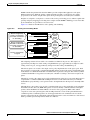
However, CTC, the ONS 15454 SONET/SDH graphical user interface (GUI), also supports the
ML-Series card. SONET/SDH circuits cannot be provisioned through Cisco IOS, but must be configured
through CTC or TL1. CTC offers ML-Series card status information, SONET/SDH alarm management,
Cisco IOS Telnet session initialization, Cisco IOS configuration file management, provisioning,
inventory, and other standard functions.
The ML100T-12 features twelve RJ-45 interfaces, and the ML100X-8 and ML1000-2 features two Small
Form-factor Pluggable (SFP) slots supporting short wavelength (SX) and long wavelength (LX) optical
modules. All three cards use the same hardware and software base and offer similar feature sets. For
detailed card specifications, refer to the “Ethernet Cards” chapter of the Cisco ONS 15454 Reference
Manual or the Cisco ONS 15454 SDH Reference Manual.
The ML-Series card features two virtual packet-over-SONET/SDH (POS) ports, which function in a
manner similar to OC-N/STM-N card ports. The SONET/SDH circuits are provisioned through CTC in
the same manner as standard OC-N/STM-N card circuits. The ML-Series POS ports support virtual
concatenation (VCAT) of SONET/SDH circuits and a software link capacity adjustment scheme
(SW-LCAS).
Ethernet Card Software Feature and Configuration Guide, R7.2
January 2009
1-1
Chapter 1 ML-Series Card Overview
ML-Series Feature List
ML-Series Feature List
The ML100T-12, ML100X-8, and ML1000-2 cards have the following features:
•
Layer 1 data features:
– 10/100BASE-TX half-duplex and full-duplex data transmission
– 100BASE-FX full-duplex data transmission with Auto-MDIX (ML100X-8)
– 1000BASE-SX, 1000BASE-LX full-duplex data transmission
– IEEE 802.3z (Gigabit Ethernet) and IEEE 802.3x (Fast Ethernet) Flow Control
•
SONET/SDH features:
– High-level data link control (HDLC) or frame-mapped generic framing procedure (GFP-F)
framing mechanism for POS
– Two POS virtual ports
– LEX, Cisco HDLC, or Point-to-Point Protocol/Bridging Control Protocol (PPP/BCP)
encapsulation for POS
– VCAT with SW-LCAS
– G-Series card and ONS 15327 E-Series card compatible (with LEX encapsulation only)
•
Layer 2 bridging features:
– Transparent bridging
– MAC address learning, aging, and switching by hardware
– Protocol tunneling
– Multiple Spanning Tree (MST) protocol tunneling
– 255 active bridge group maximum
– 60,000 MAC address maximum per card and 8,000 MAC address maximum per bridge group
– Integrated routing and bridging (IRB)
– IEEE 802.1P/Q-based VLAN trunking
– IEEE 802.1Q VLAN tunneling
– IEEE 802.1D Spanning Tree Protocol (STP) and IEEE 802.1W Rapid Spanning Tree Protocol
(RSTP)
– IEEE 802.1D STP instance per bridge group
– Ethernet over Multiprotocol Label Switching (EoMPLS)
– EoMPLS traffic engineering (EoMPLS-TE) with RSVP
– VLAN-transparent and VLAN-specific services (Ethernet Relay Multipoint Service [ERMS])
•
RPR-IEEE data path features supported:
– Bridging is supported, as specified in the IEEE 802.17b spatially aware sublayer amendment.
– Shortest path forwarding through topology discovery is supported.
– Addressing is supported, including unicast, multicast, and simple broadcast data transfers.
– Bidirectional multicast frames flood around the ring using both east and west ringlets.
– The time to live (TTL) of the multicast frames is set to the equidistant span in a closed ring and
the failed span in an open ring.
Ethernet Card Software Feature and Configuration Guide, R7.2
1-2
January 2009
Chapter 1 ML-Series Card Overview
ML-Series Feature List
•
RPR-IEEE service qualities supported:
– Per-service-quality flow-control protocols regulate traffic introduced by clients.
– Class A allocated or guaranteed bandwidth has low circumference-independent jitter.
– Class B allocated or guaranteed bandwidth has bounded circumference-dependent jitter. This
class allows for transmissions of excess information rate (EIR) bandwidths (with class C
properties).
– Class C provides best-effort services.
•
RPR-IEEE design strategies increase effective bandwidths beyond those of a broadcast ring:
– Clockwise and counterclockwise transmissions can be concurrent.
– Bandwidths can be reallocated on nonoverlapping segments.
– Bandwidth reclamation. Unused bandwidths can be reclaimed by opportunistic services.
– Spatial bandwidth reuse. Opportunistic bandwidths are reused on nonoverlapping segments.
– Temporal bandwidth reuse. Unused opportunistic bandwidth can be consumed by others.
•
RPR-IEEE fairness features ensure proper partitioning of opportunistic traffic:
– Weighted fairness allows a weighted fair access to available ring capacity.
– Aggressive fairness is supported.
– Single Choke Fairness Supports generation, termination, and processing of Single Choke
Fairness frames on both spans.
•
RPR-IEEE plug-and-play automatic topology discovery and advertisement of station capabilities
allow systems to become operational without manual intervention.
•
RPR-IEEE multiple features support robust frame transmissions:
– Service restoration time is less than 60 milliseconds after a station or link failure.
– Queue and shaper specifications avoid frame loss in normal operation.
– Fully distributed control architecture eliminates single points of failure.
– Operations, administration, and maintenance support service provider environments.
•
RPR-IEEE non-supported features:
– EoMPLS is not supported.
– IP forwarding is not supported.
– Wrapping, the optional IEEE 802.17b protection scheme, is not supported. Steering, the
protection scheme mandated by the standard, is supported.
– Layer 3 routing is not supported.
Ethernet Card Software Feature and Configuration Guide, R7.2
January 2009
1-3
Chapter 1 ML-Series Card Overview
ML-Series Feature List
•
Cisco Proprietary RPR:
– Ethernet frame check sequence (FCS) preservation for customers
– Cyclic redundancy check (CRC) error alarm generation
– FCS detection and threshold configuration
– Shortest path determination
– Keep alives
•
Fast EtherChannel (FEC) features (ML100T-12):
– Bundling of up to four Fast Ethernet ports
– Load sharing based on source and destination IP addresses of unicast packets
– Load sharing for bridge traffic based on MAC addresses
– IRB
– IEEE 802.1Q trunking
– Up to 6 active FEC port channels
•
Gigabit EtherChannel (GEC) features (ML1000-2):
– Bundling the two Gigabit Ethernet ports
– Load sharing for bridge traffic based on MAC addresses
– IRB
– IEEE 802.1Q trunking
– Auto-negotiation with Remote Fault Indication (RFI)
•
POS channel:
– Bundling the two POS ports
– LEX encapsulation only
– IRB
– IEEE 802.1Q trunking
•
Layer 3 routing, switching, and forwarding:
– Default routes
– IP unicast and multicast forwarding
– Simple IP access control lists (ACLs) (both Layer 2 and Layer 3 forwarding path)
– Extended IP ACLs in software (control-plane only)
– IP and IP multicast routing and switching between Ethernet ports
– Reverse Path Forwarding (RPF) multicast (not RPF unicast)
– Load balancing among equal cost paths based on source and destination IP addresses
– Up to 18,000 IP routes
– Up to 20,000 IP host entries
– Up to 40 IP multicast groups
– IRB routing mode support
•
Supported routing protocols:
– Virtual Private Network (VPN) Routing and Forwarding Lite (VRF Lite)
Ethernet Card Software Feature and Configuration Guide, R7.2
1-4
January 2009
Chapter 1 ML-Series Card Overview
ML-Series Feature List
– Intermediate System-to-Intermediate System (IS-IS) Protocol
– Routing Information Protocol (RIP and RIP II)
– Enhanced Interior Gateway Routing Protocol (EIGRP)
– Open Shortest Path First (OSPF) Protocol
– Protocol Independent Multicast (PIM)—Sparse, sparse-dense, and dense modes
– Secondary addressing
– Static routes
– Local proxy ARP
– Border Gateway Protocol (BGP)
– Classless interdomain routing (CIDR)
•
Quality of service (QoS) features:
– Multicast priority queuing classes
– Service level agreements (SLAs) with 1-Mbps granularity
– Input policing
– Guaranteed bandwidth (weighted round-robin [WDRR] plus strict priority scheduling)
– Low latency queuing support for unicast Voice-over-IP (VoIP)
– Class of service (CoS) based on Layer 2 priority, VLAN ID, Layer 3 Type of Service/DiffServ
Code Point (TOS/DSCP), and port
– CoS-based packet statistics
•
Security features:
– Cisco IOS login enhancements
– Secure Shell connection (SSH Version 2)
– Disabled console port
– Authentication, Authorization, and Accounting/Remote Authentication Dial-In User Service
(AAA/RADIUS) stand alone mode
– AAA/RADIUS relay mode
•
Additional protocols:
– Cisco Discovery Protocol (CDP) support on Ethernet ports
– Dynamic Host Configuration Protocol (DHCP) relay
– Hot Standby Router Protocol (HSRP) over 10/100 Ethernet, Gigabit Ethernet, FEC, GEC, and
Bridge Group Virtual Interface (BVI)
– Internet Control Message Protocol (ICMP)
•
Management features:
– Cisco IOS
– CTC
– CTM
– Remote monitoring (RMON)
– Simple Network Management Protocol (SNMP)
Ethernet Card Software Feature and Configuration Guide, R7.2
January 2009
1-5
Chapter 1 ML-Series Card Overview
ML-Series Feature List
– Transaction Language 1 (TL1)
•
System features:
– Automatic field programmable gate array (FPGA) Upgrade
– Network Equipment Building Systems 3 (NEBS3) compliant
– Multiple microcode images
•
CTC features:
– Framing Mode Provisioning
– Standard STS/STM and VCAT circuit provisioning for POS virtual ports
– SONET/SDH alarm reporting for path alarms and other ML-Series card specific alarms,
including RPR-WRAP
– Raw port statistics
– Standard inventory and card management functions
– J1 path trace
– Cisco IOS CLI Telnet sessions from CTC
– Cisco IOS startup configuration file management from CTC
Ethernet Card Software Feature and Configuration Guide, R7.2
1-6
January 2009
C H A P T E R
2
CTC Operations
This chapter covers Cisco Transport Controller (CTC) operations of the ML-Series card. All operations
described in the chapter take place at the card-level view of CTC. CTC shows provisioning information
and statistics for both the Ethernet and packet-over-SONET/SDH (POS) ports of the ML-Series card.
For the ML-Series cards, CTC manages SONET/SDH alarms and provisions STS/STM circuits in the
same manner as other ONS 15454 SONET/SDH traffic cards.
Use CTC to load a Cisco IOS configuration file or to open a Cisco IOS command-line interface (CLI)
session. See Chapter 3, “Initial Configuration.”
This chapter contains the following major sections:
•
Displaying ML-Series POS And Ethernet Statistics on CTC, page 2-1
•
Displaying ML-Series Ethernet Ports Provisioning Information on CTC, page 2-2
•
Displaying ML-Series POS Ports Provisioning Information on CTC, page 2-3
•
Provisioning Card Mode, page 2-4
•
Managing SONET/SDH Alarms, page 2-4
•
Displaying the FPGA Information, page 2-4
•
Provisioning SONET/SDH Circuits, page 2-5
•
J1 Path Trace, page 2-5
Displaying ML-Series POS And Ethernet Statistics on CTC
The POS statistics window lists POS port-level statistics. Display the CTC card view for the ML-Series
card and click the Performance > POS Ports tabs to display the window.
The Ethernet statistics window lists Ethernet port-level statistics. It is similar in appearance to the POS
statistics window. The ML-Series Ethernet ports are zero based. Display the CTC card view for the
ML-Series card and click the Performance > Ether Ports tabs to display the window. Table 2-1
describes the buttons in the POS Ports and Ether Ports window.
A different set of statistics appears for the ML-Series card depending on whether the card is using HDLC
or GFP-F framing. For definitions of ML-Series card statistics, refer to the “Performance Monitoring”
chapter of the Cisco ONS 15454 SONET and DWDM Troubleshooting Guide or the Cisco ONS 15454
SDH Troubleshooting Guide.
Ethernet Card Software Feature and Configuration Guide, R7.2
January 2009
2-1
Chapter 2 CTC Operations
Displaying ML-Series Ethernet Ports Provisioning Information on CTC
Table 2-1
ML-Series POS and Ethernet Statistics Fields and Buttons
Button
Description
Refresh
Manually refreshes the statistics.
Baseline
Resets the software counters (in that particular CTC client only) temporarily to zero
without affecting the actual statistics on the card. From that point on, only counters
displaying the change from the temporary baseline are displayed by this CTC client.
These new baselined counters are shown only as long as the user displays the
Performance window. If the user navigates to another CTC window and comes back
to the Performance window, the true actual statistics retained by the card are shown.
Auto-Refresh
Sets a time interval for the automatic refresh of statistics.
Displaying ML-Series Ethernet Ports Provisioning Information
on CTC
The Ethernet port provisioning window displays the provisioning status of the Ethernet ports. Click the
Provisioning > Ether Ports tabs to display this window. For ML-Series cards, only the Port Name field
can be provisioned from CTC. The user must configure ML-Series ports using the Cisco IOS CLI.
Auto in a column indicates the port is set to autonegotiate capabilities with the attached link partner.
All ML-Series cards do not display all columns. Table 2-2 details the information displayed under the
Provisioning > Ether Ports tab:
Table 2-2
CTC Display of Ethernet Port Provisioning Status
Column
Description
ML1000-2
ML100T-12
ML100X-8
Port
The fixed number identifier for the
specific port.
0 or 1
0-11
0-7
Port Name
Configurable 12-character
alphanumeric identifier for the port.
User specific
User specific
User
specific
Admin State Configured port state, which is
administratively active or inactive.
UP and DOWN UP and
DOWN
UP and
DOWN
Link State
Status between signaling points at port UP and DOWN UP and
and attached device.
DOWN
UP and
DOWN
MTU
(Maximum Transmission Unit) Largest Default value is Default value
acceptable packet size configured for
1500
is 1500
that port.
Default
value is
1500
Speed
Ethernet port transmission speed.
100Mbps
Duplex
Setting of the duplex mode for the port. —
—
Auto,
10Mbps, or
100Mbps
Auto, Full, or Full
Half
Ethernet Card Software Feature and Configuration Guide, R7.2
2-2
January 2009
Chapter 2 CTC Operations
Displaying ML-Series POS Ports Provisioning Information on CTC
Table 2-2
CTC Display of Ethernet Port Provisioning Status (continued)
Column
Description
ML1000-2
Flow
Control
Flow control mode negotiated with peer Asymmetrical, Symmetrical
device. These values are displayed but Symmetrical or or None
not configureable in CTC.
None
Symmetrical
or None
Optics
Small form-factor pluggable (SFP)
physical media type.
Unplugged,
100 FX, or
100 LX
Unplugged,
1000 SX, or
1000 LX
ML100T-12
—
ML100X-8
Note
The 100 FX value in the Optics column of the ML100X-8 represent the short wavelength (SX) SFP.
Note
The port name field configured in CTC and the port name configured in Cisco IOS are independent of
each other. The name for the same port under Cisco IOS and CTC does not match, unless the same name
is used to configure the port name in both CTC and Cisco IOS.
Displaying ML-Series POS Ports Provisioning Information on
CTC
The POS ports provisioning window displays the provisioning status of the card’s POS ports. Click the
Provisioning > POS Ports tabs to display this window. For ML-Series cards, only the POS Port Name
field can be provisioned from CTC. The user must configure ML-Series ports through the Cisco IOS
CLI.
Table 2-3 details the information displayed under the Provisioning > POS Ports tab.
Table 2-3
CTC Display of POS Port Provisioning Status
Column
Description
Port
The fixed number identifier for the specific port.
Port Name
Configurable 12-character alphanumeric identifier for the port.
Admin State
Configured port state, which is administratively active or inactive. Possible
values are UP and DOWN. For the UP value to appear, a POS port must be
both administratively active and have a SONET/SDH circuit provisioned.
Link State
Status between signaling points at port and attached device. Possible values
are UP and DOWN.
MTU
The maximum transfer unit, which is the largest acceptable packet size
configured for that port. The maximum setting is 9000. The default size is
1500 for the G-Series card compatible encapsulation (LEX) and 4470 for
Cisco HDLC and Point-to-Point Protocol/Bridging Control Protocol
(PPP/BCP) encapsulation.
Framing Type
HDLC or frame-mapped generic framing procedure (GFP-F) framing type
shows the POS framing mechanism being employed on the port.
Ethernet Card Software Feature and Configuration Guide, R7.2
January 2009
2-3
Chapter 2 CTC Operations
Provisioning Card Mode
Note
The port name field configured in CTC and the port name configured in Cisco IOS are independent of
each other. The name for the same port under Cisco IOS and CTC does not match, unless the same name
is used to configure the port name in both CTC and Cisco IOS.
Provisioning Card Mode
The card mode provisioning window shows the mode currently configured on the ML-Series card and
allows the user to change it to either HDLC, GFP-F, or 802.17 RPR. For more information on HDLC or
GFP-F, see the "POS on ONS Ethernet Cards" chapter.
The user may also pre-provision the card mode of an ML-Series card before the card is physically
installed. The ML-Series card will then boot up into the pre-provisioned mode. If the correct microcode
image is not already loaded, setting the card mode to 802.17 will automatically download and enable the
correct microcode image for IEEE compliant 802.17b.
Caution
The ML-Series card reboots after the card mode is changed.
Click the Provisioning > Card tabs to display this window. Use the Mode drop-down list and then click
Apply to provision the card mode type. Click Yes at the Reset Card dialog box that appears.
Managing SONET/SDH Alarms
CTC manages the ML-Series SONET/SDH alarm behavior in the same manner as it manages alarm
behavior for other ONS 15454 SONET/SDH cards. Refer to the “Manage Alarms” chapter of the
Cisco ONS 15454 Procedure Guide or the Cisco ONS 15454 SDH Procedure Guide for detailed
information. For information on specific alarms, refer to the “Alarm Troubleshooting” chapter of the
Cisco ONS 15454 Troubleshooting Guide or Cisco ONS 15454 SDH Troubleshooting Guide for detailed
information.
To view the window, click the Provisioning > Alarm Profiles tabs for the Ethernet and POS port alarm
profile information.
Displaying the FPGA Information
CTC displays information for the field programmable gate array (FPGA) on the ML-Series card. Click
the Maintenance > Info tabs to display this window.
The FPGA on the ML100T-12, ML100X-8 and ML1000-2 provides the interface and buffering between
the card’s network processor and the SONET/SDH cross-connect. FPGA Image Version 3.x supports
HDLC framing, and FPGA Image Version 4.x supports GFP-F Framing. Both images support virtual
concatenation (VCAT). In Release 5.0 and later, the correct FPGA is automatically loaded when the
framing mode is changed by the user.
Note
ML-Series cards manufactured prior to Software Release 4.6 need an updated version of the FPGA to
support VCAT.
Ethernet Card Software Feature and Configuration Guide, R7.2
2-4
January 2009
Chapter 2 CTC Operations
Provisioning SONET/SDH Circuits
Caution
Do not attempt to use current FPGA images with an earlier CTC software release.
Provisioning SONET/SDH Circuits
CTC provisions and edits STS/STM level circuits for the two virtual SONET/SDH ports of the
ML-Series card in the same manner as it provisions other ONS 15454 SONET/SDH OC-N cards. The
ONS 15454 ML-Series card supports both contiguous concatenation (CCAT) and virtual concatenation
(VCAT) circuits.
For step-by-step instructions to configure an ML-Series card SONET CCAT or VCAT circuit, refer to
the “Create Circuits and VT Tunnels” chapter of the Cisco ONS 15454 Procedure Guide. For
step-by-step instructions to configure an ML-Series card SDH CCAT or VCAT circuit, refer to the
“Create Circuits and Tunnels” chapter of the Cisco ONS 15454 SDH Procedure Guide. For more
general information on VCAT circuits, refer to the “Circuits and Tunnels” chapter of the Cisco ONS
15454 Reference Manual or the Cisco ONS 15454 SDH Reference Manual.
J1 Path Trace
The J1 Path Trace is a repeated, fixed-length string comprised of 64 consecutive J1 bytes. You can use
the string to monitor interruptions or changes to SONET/SDH circuit traffic. For information on J1 Path
Trace, refer to the Cisco ONS 15454 Reference Manual or the Cisco ONS 15454 SDH Reference
Manual.
Ethernet Card Software Feature and Configuration Guide, R7.2
January 2009
2-5
Chapter 2 CTC Operations
J1 Path Trace
Ethernet Card Software Feature and Configuration Guide, R7.2
2-6
January 2009
C H A P T E R
3
Initial Configuration
This chapter describes the initial configuration of the ML-Series card and contains the following major
sections:
•
Hardware Installation, page 3-1
•
Cisco IOS on the ML-Series Card, page 3-2
•
Startup Configuration File, page 3-7
•
Multiple Microcode Images, page 3-11
•
Changing the Working Microcode Image, page 3-12
•
Cisco IOS Command Modes, page 3-13
•
Using the Command Modes, page 3-15
Hardware Installation
This section lists hardware installation tasks, including booting up the ML-Series card. Because
ONS 15454 SONET/SDH card slots can be preprovisioned for an ML-Series line card, the following
physical operations can be performed before or after the provisioning of the slot has taken place.
Note
1.
Install the ML-Series card into the ONS 15454 SONET/SDH. See Chapter 2, “Install Cards and
Fiber-Optic Cable” of the Cisco ONS 15454 Procedure Guide or Cisco ONS 15454 SDH Procedure
Guide for information.
2.
Connect the cables to the front ports of the ML-Series card.
3.
(Optional) Connect the console terminal to the ML-Series card.
A NO-CONFIG condition is reported in CTC under the Alarms pane when an ML-Series card is inserted
and no valid Cisco IOS startup configuration file exists. Loading or creating this file clears the condition.
See the “Startup Configuration File” section on page 3-7 for information on loading or creating the file.
Ethernet Card Software Feature and Configuration Guide, R7.2
January 2009
3-1
Chapter 3 Initial Configuration
Cisco IOS on the ML-Series Card
Cisco IOS on the ML-Series Card
The Cisco IOS software image used by the ML-Series card is not permanently stored on the ML-Series
card but in the flash memory of the TCC2/TCC2P card. During a hard reset, when a card is physically
removed and reinserted or power is otherwise lost to the card, the Cisco IOS software image is downloaded
from the flash memory of the TCC2/TCC2P to the memory cache of the ML-Series card. The cached
image is then decompressed and initialized for use by the ML-Series card.
During a soft reset, when the ML-Series card is reset through CTC or the Cisco IOS command line
interface (CLI) command reload, the ML-Series card checks its cache for a Cisco IOS image. If a valid
and current Cisco IOS image exists, the ML-Series card decompresses and initializes the image. If the
image does not exist, the ML-Series requests a new copy of the Cisco IOS image from the TCC2/TCC2P.
Caching the Cisco IOS image provides a significant time savings when a warm reset is performed.
There are four ways to access the ML-Series card Cisco IOS configuration. The two out-of-band options
are opening a Cisco IOS session on CTC and telnetting to the node IP Address and slot number plus
2000. The two-in-band signalling options are telnetting to a configured management interface and
directly connecting to the console port.
Opening a Cisco IOS Session Using CTC
Users can initiate a Cisco IOS CLI session for the ML-Series card using CTC. Click the IOS tab at the
card-level CTC view, then click the Open IOS Command Line Interface (CLI) button (Figure 3-1). A
window opens and a standard Cisco IOS CLI User EXEC command mode prompt appears.
Note
A Cisco IOS startup configuration file must be loaded and the ML-Series card must be installed and
initialized prior to opening a Cisco IOS CLI session on CTC. See the “Startup Configuration File”
section on page 3-7 for more information.
Ethernet Card Software Feature and Configuration Guide, R7.2
3-2
January 2009
Chapter 3 Initial Configuration
Telnetting to the Node IP Address and Slot Number
Figure 3-1
CTC IOS Window
Telnetting to the Node IP Address and Slot Number
Users can telnet to the Cisco IOS CLI using the IP address and the slot number of the
ONS 15454 SONET/SDH plus 2000.
Note
A Cisco IOS startup configuration file must be loaded and the ML-Series card must be installed and
initialized prior to telnetting to the IP address and slot number plus 2000. See the “Startup Configuration
File” section on page 3-7 for more information.
Note
If the ONS 15454 SONET/SDH node is set up as a proxy server, where one ONS 15454 SONET/SDH
node in the ring acts as a gateway network element (GNE) for the other nodes in the ring, telnetting over
the GNE firewall to the IP address and slot number of a non-GNE or end network element (ENE) requires
the user’s Telnet client to be SOCKS v5 aware (RFC 1928). Configure the Telnet client to recognize the
GNE as the Socks v5 proxy for the Telnet session and to recognize the ENE as the host.
Step 1
Obtain the node IP address from the LCD on the front of the physical ONS 15454 SONET/SDH or the
IP Addr field shown at the CTC node view (Figure 3-2).
Step 2
Identify the slot number containing the targeted ML-Series card from either the physical
ONS 15454 SONET/SDH or the CTC node view (Figure 3-2). For example, Slot 13.
Ethernet Card Software Feature and Configuration Guide, R7.2
January 2009
3-3
Chapter 3 Initial Configuration
Telnetting to a Management Port
Figure 3-2
CTC Node View Showing IP Address and Slot Number
131940
Node IP address
Step 3
Use the IP address and the total of the slot number plus 2000 as the Telnet address in your preferred
communication program. For example, for an IP address of 10.92.18.124 and Slot 13, you would enter
or telnet 10.92.18.124 2013.
Telnetting to a Management Port
Users can access the ML-Series through a standard Cisco IOS management port in the same manner as
other Cisco IOS platforms. For further details about configuring ports and lines for management access,
refer to the Cisco IOS Configuration Fundamentals Configuration Guide.
As a security measure, the vty lines used for Telnet access are not fully configured. In order to gain
Telnet access to the ML-Series card, you must configure the vty lines via the serial console connection
or preload a startup-configuration file that configures the vty lines. A port on the ML-Series must first
be configured as the management port; see “Configuring the Management Port” section on page 3-8.
ML-Series IOS CLI Console Port
The ML-Series card has an RJ-11 serial console port on the card faceplate labeled CONSOLE. The
console port is wired as data circuit-terminating equipment (DCE). It enables communication from the
serial port of a PC or workstation running terminal emulation software to the Cisco IOS CLI on a specific
ML-Series card.
Ethernet Card Software Feature and Configuration Guide, R7.2
3-4
January 2009
Chapter 3 Initial Configuration
ML-Series IOS CLI Console Port
RJ-11 to RJ-45 Console Cable Adapter
Due to space limitations on the ML-Series card faceplate, the console port is an RJ-11 modular jack
instead of the more common RJ-45 modular jack. Cisco supplies an RJ-11 to RJ-45 console cable adapter
(P/N 15454-CONSOLE-02) with each ML-Series card. After connecting the adapter, the console port
functions like the standard Cisco RJ-45 console port. Figure 3-3 shows the RJ-11 to RJ-45 console cable
adapter.
Console Cable Adapter
78970
Figure 3-3
Table 3-1 shows the mapping of the RJ-11 pins to the RJ-45 pins.
Table 3-1
RJ-11 to RJ-45 Pin Mapping
RJ-11 Pin RJ-45 Pin
1
1
2
2
3
3
4
4
None
5
5
6
None
7
6
8
Connecting a PC or Terminal to the Console Port
Use the supplied cable, an RJ-11 to RJ-45 console cable adapter, and a DB-9 adapter to connect a PC to
the ML-Series console port.
The PC must support VT100 terminal emulation. The terminal-emulation software—frequently a PC
application such as HyperTerminal or Procomm Plus—makes communication between the ML-Series
and your PC or terminal possible during the setup program.
Step 1
Step 2
Configure the data rate and character format of the PC or terminal to match these console port default
settings:
•
9600 baud
•
8 data bits
•
1 stop bit
•
No parity
Insert the RJ-45 connector of the supplied cable into the female end of the supplied console cable
adapter.
Ethernet Card Software Feature and Configuration Guide, R7.2
January 2009
3-5
Chapter 3 Initial Configuration
ML-Series IOS CLI Console Port
Step 3
Insert the RJ-11 modular plug end of the supplied console cable adapter into the RJ-11 serial console
port, labeled CONSOLE, on the ML-Series card faceplate. Figure 3-4 shows the ML1000-2 faceplate
with console port. For the ML100T-12 and ML100X-8, the console port is at the bottom of the card
faceplate.
Figure 3-4
Connecting to the Console Port
ML1000
2
FAIL
ACT
CONSOLE
ML1000-2 CONSOLE Port
for RJ-11 Module Plug
TX
1
RX
LINK
ACT
RJ-45 Cable
TX
2
RX
LINK
ACT
78994
RJ-11 to RJ-45
Console Port Adapter Cable
Step 4
Attach the supplied RJ-45-to-DB-9 female DTE adapter to the nine-pin DB-9 serial port on the PC.
Step 5
Insert the other end of the supplied cable in the attached adapter.
Ethernet Card Software Feature and Configuration Guide, R7.2
3-6
January 2009
Chapter 3 Initial Configuration
Startup Configuration File
Startup Configuration File
The ML-Series card needs a startup configuration file in order to configure itself beyond the default
configuration when the card is reset. If no startup configuration file exists in the TCC2/TCC2P flash
memory, then the card boots up to a default configuration. Users can manually set up the startup
configuration file through the serial console port and the Cisco IOS CLI configuration mode or load a
Cisco IOS supplied sample startup configuration file through CTC. A running configuration becomes a
startup configuration file when saved with a copy running-config startup-config command.
It is not possible to establish a Telnet connection to the ML-Series card until a startup configuration filed
is loaded onto the ML-Series card. Access is available through the console port.
Caution
The copy running-config startup-config command saves a startup configuration file to the flash
memory on the ML-Series card. This operation is confirmed by the appearance of [OK] in the Cisco IOS
CLI session. The startup configuration file is also saved to the ONS node’s database restoration file after
approximately 30 additional seconds.
Caution
Accessing the read-only memory monitor mode (ROMMON) on the ML-Series card without the
assistance of Cisco personnel is not recommended. This mode allows actions that can render the
ML-Series card inoperable. The ML-Series card ROMMON is preconfigured to boot the correct Cisco
IOS software image for the ML-Series card.
Caution
The maximum size of the startup configuration file is 98356 bytes (characters).
Note
When the running configuration file is altered, a RUNCFG-SAVENEED condition appears in CTC. This
condition is a reminder to enter a copy running-config startup-config command in the Cisco IOS CLI,
or the changes will be lost when the ML-Series card reboots.
Manually Creating a Startup Configuration File Through the Serial Console Port
Configuration through the serial console port is familiar to those who have worked with other products
using Cisco IOS. At the end of the configuration procedure, the copy running-config startup-config
command saves a startup configuration file.
The serial console port gives the user visibility to the entire booting process of the ML-Series card.
During initialization the ML-Series card first checks for a locally, valid cached copy of Cisco IOS. It
then either downloads the Cisco IOS software image from the TCC2/TCC2P or proceeds directly to
decompressing and initializing the image. Following Cisco IOS initialization the CLI prompt appears,
at which time the user can enter the Cisco IOS CLI configuration mode and setup the basic ML-Series
configuration.
Ethernet Card Software Feature and Configuration Guide, R7.2
January 2009
3-7
Chapter 3 Initial Configuration
Manually Creating a Startup Configuration File Through the Serial Console Port
Passwords
There are two types of passwords that you can configure for an ML-Series card: an enable password and
an enable secret password. For maximum security, make the enable password different from the enable
secret password.
•
Enable password—The enable password is a non-encrypted password. It can contain any number of
uppercase and lowercase alphanumeric characters. Give the enable password only to users permitted
to make configuration changes to the ML-Series card.
•
Enable secret password—The enable secret password is a secure, encrypted password. By setting an
encrypted password, you can prevent unauthorized configuration changes. On systems running
Cisco IOS software, you must enter the enable secret password before you can access global
configuration mode.
An enable secret password can contain from 1 to 25 uppercase and lowercase alphanumeric
characters. The first character cannot be a number. Spaces are valid password characters. Leading
spaces are ignored; trailing spaces are recognized.
Passwords are configured in the “Configuring the Management Port” section on page 3-8.
Configuring the Management Port
Because there is no separate management port on ML-Series cards, any Fast Ethernet interface (0-11 on
the ML100T-12 card and 0-7 on the ML100X-8), any Gigabit Ethernet interface (0-1 on the ML1000-2
card), or any POS interface (0-1 on any ML-Series card) can be configured as a management port. For
the packet over SONET (POS) interface to exist, an STS or STM circuit must first be created through
CTC or TL1.
You can remotely configure the ML-Series card through the management port, but first you must
configure an IP address so that the ML-Series card is reachable or load a startup configuration file. You
can manually configure the management port interface from the Cisco IOS CLI via the serial console
connection.
To configure Telnet for remote management access, perform the following procedure, beginning in user
EXEC mode:
Step 1
Command
Purpose
Router> enable
Router#
Activates user EXEC (or enable) mode.
The # prompt indicates enable mode.
Step 2
Router# configure terminal
Router(config)#
Activates global configuration mode. You can abbreviate
the command to config t. The Router(config)# prompt
indicates that you are in global configuration mode.
Step 3
Router(config)# enable password
password
Sets the enable password. See the “Passwords” section
on page 3-8.
Step 4
Router(config)# enable secret password
Allows you to enter an enable secret password. See the
“Passwords” section on page 3-8. A user must enter the
enable secret password to gain access to global
configuration mode.
Step 5
Router(config)# interface type number
Router(config-if)#
Activates interface configuration mode on the interface.
Step 6
Router(config-if)# ip address
ip-address subnetmask
Allows you to enter the IP address and IP subnet mask
for the interface specified in Step 5.
Ethernet Card Software Feature and Configuration Guide, R7.2
3-8
January 2009
Chapter 3 Initial Configuration
CTC and the Startup Configuration File
Command
Purpose
Step 7
Router(config-if)# no shutdown
Enables the interface.
Step 8
Router(config-if)# exit
Router(config)#
Returns to global configuration mode.
Step 9
Router(config)# line vty line-number
Router(config-line)#
Activates line configuration mode for virtual terminal
connections. Commands entered in this mode control the
operation of Telnet sessions to the ML-Series card.
Step 10 Router(config-line)# password password
Allows you to enter a password for Telnet sessions.
Step 11 Router(config-line)# end
Returns to privileged EXEC mode.
Router#
Step 12 Router# copy running-config
(Optional) Saves your configuration changes to
NVRAM.
startup-config
After you have completed configuring remote management on the management port, you can use Telnet
to remotely assign and verify configurations.
Configuring the Hostname
In addition to the system passwords and enable password, your initial configuration should include a
hostname to easily identify your ML-Series card. To configure the hostname, perform the following task,
beginning in enable mode:
Command
Purpose
Step 1
Router# configure terminal
Router(config)#
Activates global configuration mode.
Step 2
Router(config)# hostname name-string
Allows you to enter a system name. In this
example, we set the hostname to “Router.”
Step 3
Router(config)# end
Router#
Returns to privileged EXEC mode.
Step 4
Router# copy running-config
startup-config
(Optional) Copies your configuration changes
to NVRAM.
CTC and the Startup Configuration File
CTC allows a user to load the startup configuration file required by the ML-Series card. A
Cisco-supplied sample Cisco IOS startup configuration file, named Basic-IOS-startup-config.txt, is
available on the Cisco ONS 15454 SONET/SDH software CD. CISCO15 is the Cisco IOS CLI default
line password and the enable password for this configuration. Users can also create their own startup
configuration file, see the “Manually Creating a Startup Configuration File Through the Serial Console
Port” section on page 3-7.
CTC can load a Cisco IOS startup configuration file into the TCC2/TCC2P card flash before the
ML-Series card is physically installed in the slot. When installed, the ML-Series card downloads and
applies the Cisco IOS software image and the preloaded Cisco IOS startup-configuration file. Preloading
the startup configuration file allows an ML-Series card to immediately operate as a fully configured card
when inserted into the ONS 15454 SONET/SDH.
Ethernet Card Software Feature and Configuration Guide, R7.2
January 2009
3-9
Chapter 3 Initial Configuration
CTC and the Startup Configuration File
If the ML-Series card is booted up prior to the loading of the Cisco IOS startup configuration file into
TCC2/TCC2P card flash, then the ML-Series card must be reset to use the Cisco IOS startup
configuration file or the user can issue the command copy start run at the Cisco IOS CLI to configure
the ML-Series card to use the Cisco IOS startup configuration file.
Loading a Cisco IOS Startup Configuration File Through CTC
This procedure details the initial loading of a Cisco IOS Startup Configuration file through CTC.
Step 1
At the card-level view of the ML-Series card, click the IOS tab.
The CTC IOS window appears (Figure 3-1 on page 3-3).
Step 2
Click the IOS startup config button.
The config file dialog box appears.
Step 3
Click the Local -> TCC button.
Step 4
The sample Cisco IOS startup configuration file can be installed from either the ONS 15454
SONET/SDH software CD or from a PC or network folder:
Step 5
•
To install the Cisco supplied startup config file from the ONS 15454 SONET/SDH software CD,
insert the CD into the CD drive of the PC or workstation. Using the CTC config file dialog, navigate
to the CD drive of the PC or workstation and double-click the Basic-IOS-startup-config.txt file.
•
To install the Cisco supplied config file from a PC or network folder, navigate to the folder
containing the desired Cisco IOS startup config file and double-click the desired Cisco IOS startup
config file.
At the Are you sure? dialog box, click the Yes button.
The Directory and Filename fields on the configuration file dialog update to reflect that the Cisco IOS
startup config file is loaded onto the TCC2/TCC2P.
Step 6
Load the IOS startup config file from the TCC2/TCC2P to the ML-Series card:
a.
If the ML-Series card has already been installed, right-click on the ML-Series card at the node level
or card level CTC view and select Reset Card.
After the reset, the ML-Series card runs under the newly loaded Cisco IOS startup config.
b.
Note
If the ML-Series card is not yet installed, installing the ML-Series card into the slot loads and runs
the newly loaded Cisco IOS startup configuration on the ML-Series card.
When the Cisco IOS startup configuration file is downloaded and parsed at initialization, if there
is an error in the parsing of this file, an ERROR-CONFIG alarm is reported and appears under
the CTC alarms pane or in TL1. No other Cisco IOS error messages regarding the parsing of text
are reported to the CTC or in TL1. An experienced Cisco IOS user can locate and troubleshoot
the line in the startup configuration file that produced the parsing error by opening the Cisco IOS
CLI and entering a copy start run command.
Ethernet Card Software Feature and Configuration Guide, R7.2
3-10
January 2009
Chapter 3 Initial Configuration
Multiple Microcode Images
Note
A standard ONS 15454 SONET/SDH database restore reinstalls the Cisco IOS startup config file
on the TCC2/TCC2P, but does not implement the Cisco IOS startup config on the ML-Series.
See the “Database Restore of the Startup Configuration File” section on page 3-11 for additional
information.
Database Restore of the Startup Configuration File
The ONS 15454 SONET/SDH includes a database restoration feature. Restoring the database will
reconfigure a node and the installed line cards to the saved provisioning, except for the ML-Series card.
The ML-Series card does not automatically restore the startup configuration file saved in the
TCC2/TCC2P database.
A user can load the saved startup configuration file onto the ML-Series card in two ways. He can revert
completely to the saved startup configuration and lose any additional provisioning in the unsaved
running configuration, which is a restoration scheme similar to other ONS cards, or he can install the
saved startup configuration file on top of the current running configuration, which is a merging
restoration scheme used by many Cisco Catalyst devices.
To revert completely to the startup configuration file saved in the restored database, the user needs to
reset the ML-Series card. Right-click the ML-Series card in CTC and choose Reset or use the Cisco IOS
CLI reload command to reset the ML-Series card.
Caution
Resetting the ONS 15454 ML-Series card causes a loss of traffic and closes any Telnet
sessions to the card.
To merge the saved startup configuration file with the running configuration, use the Cisco IOS CLI copy
startup-config running-config command. This restoration scheme should only be used by experienced
users with an understanding of the current running configuration and the Cisco IOS copy command. The
copy startup-config running-config command will not reset the ML-Series card. The user also needs
to use the Cisco IOS CLI copy running-config startup-config command to save the new merged
running configuration to the startup configuration file.
Multiple Microcode Images
The primary packet processing and forwarding on the ML-Series card is done by the network processor,
which is controlled by microcode. This microcode is a set of instructions (software) loaded into the
network processor and executed at high speed. The network processor has limited microcode storage
space.
Some of the ML-Series card features require significant amounts of microcode, and this additional
microcode exceeds the storage capacity of the network processor. These features are added as new
microcode images (separate microcode programs). The network processor can only hold one microcode
image at a time, and changing the loaded microcode image requires resetting the network processor.
The user can choose from several microcode images for the ML-Series card. Table 3-2 compares the
features available with the different microcode images.
Ethernet Card Software Feature and Configuration Guide, R7.2
January 2009
3-11
Chapter 3 Initial Configuration
Changing the Working Microcode Image
Caution
Configuring topology discovery or shortest path load balancing on an ML-Series card with the SW-RPR
microcode image disables support for Cisco Proprietary RPR DRPRI.
Table 3-2
Microcode Image Feature Comparison
Features
Base
Enhanced EoMPLS SW-RPR 802.17
Packet Classification
Yes
Yes
Yes
Yes
Yes
Policing and QoS
Yes
Yes
Yes
Yes
Yes
Layer 2 Bridging
Yes
Yes
Yes
Yes
Yes
IP Unicast Switching
Yes
Yes
Yes
Yes
No
IP Fragmentation
Yes
No
No
No
No
IP Multicast Switching
Yes
No
No
No
No
EoMPLS
No
No
Yes
No
Future
Cisco Proprietary RPR Encapsulation
Yes
Yes
Yes
Yes
No
Cisco Proprietary RPR Resiliency Enhancements: No
No
Yes
Yes
No
•
Cisco Proprietary RPR Keep Alive
•
Cisco Proprietary RPR CRC Threshold
Configuration, Detection, and Wrap
•
Cisco Proprietary RPR Customer Ethernet
FCS Preservation
•
Cisco Proprietary RPR CRC Error Alarm
Generation
•
Cisco Proprietary RPR Shortest Path
Determination and Topology Discovery
PPP/HDLC/LEX Encapsulation Support
Yes
Yes
Yes
No
No
IEEE 802.17b
No
No
No
No
Yes
Enhanced PM
No
Yes
No
Yes
Yes
Redundant Interconnect
No
No
Yes
Yes
Yes
Changing the Working Microcode Image
The user can change the microcode image using Cisco IOS CLI configuration and a reset of the
ML-Series card. Using this configuration method, you can load any microcode image except 802.17. To
automatically download and enable the 802.17 microcode image, use CTC to set the card mode to
802.17. For more information, see the “Provisioning Card Mode” section on page 2-4.
To configure a working microcode image, perform the following procedure, beginning in global
configuration mode:
Ethernet Card Software Feature and Configuration Guide, R7.2
3-12
January 2009
Chapter 3 Initial Configuration
Cisco IOS Command Modes
Step 1
Command
Purpose
Router(config)# microcode {base | enhanced
| fail system-reload | mpls | spr}
Configures the ML-Series card with the selected
microcode image:
base—(Default) Enables base features only. Base
features include Multicast routing and IP
fragmentation.
enhanced—Enables ERMS, enhanced packet
statistics, and enhanced DRPRI. Disables
multicast routing and IP fragmentation.
fail system-reload—This command and feature
are specific to ML-Series card. In the event of a
microcode failure, it configures the ML-Series
card to save information to the flash memory and
then reboot. The information is saved for use by
the Cisco Technical Assistance Center (Cisco
TAC). To contact TAC, see the “Obtaining
Documentation and Submitting a Service
Request” section on page xxxvii.
mpls—Enables MPLS. Disables IP multicast, IP
fragmentation, and ERMS support.
spr—Enables SPR encapsulation, Enhanced
Packet Statistics, DRPRI, and Keepalives.
Disables Multicast routing or IP Fragmentation.
Step 2
Router(config)# exit
Exits global configuration mode.
Step 3
Router# copy running-config startup-config
Saves the configuration changes to Flash memory.
The running configuration file configured with the
new microcode image choice must be saved as a
startup configuration file for the ML-Series card to
reboot with the new microcode image choice.
Step 4
Router# reload
Resets the ML-Series card and loads the new
microcode image.
Caution
Step 5
Router# show microcode
Resetting the ML-Series card causes a
loss of traffic and closes any Telnet
sessions to the card.
Shows the microcode image currently loaded and
the microcode image that loads when the
ML-Series card resets.
Cisco IOS Command Modes
The Cisco IOS user interface has several different modes. The commands available to you depend on
which mode you are in. To get a list of the commands available in a given mode, type a question mark
(?) at the system prompt.
Ethernet Card Software Feature and Configuration Guide, R7.2
January 2009
3-13
Chapter 3 Initial Configuration
Cisco IOS Command Modes
Table 3-3 describes the most commonly used modes, how to enter the modes, and the resulting system
prompts. The system prompt helps you identify which mode you are in and, therefore, which commands
are available to you.
Note
Table 3-3
When a process makes unusually heavy demands on the CPU of the ML-Series card, it may impair CPU
response time and cause a CPUHOG error message to appear on the console. This message indicates
which process used a large number of CPU cycles, such as the updating of the routing table with a large
number of routes due to an event. Seeing this message as a result of card reset or other infrequent events
should not be a cause for concern.
Cisco IOS Command Modes
Mode
What You Use It For
How to Access
Prompt
User EXEC
Connect to remote devices,
change terminal settings on a
temporary basis, perform basic
tests, and display system
information.
Log in.
Router>
Privileged EXEC
(also called Enable
mode)
Set operating parameters. The
From user EXEC mode, enter the
privileged command set includes enable command and the enable
the commands in user EXEC
password.
mode, as well as the configure
command. Use this command
mode to access the other
command modes.
Router#
Global configuration
Configure features that affect the From privileged EXEC mode,
system as a whole.
enter the configure terminal
command.
Router(config)#
Interface configuration Enable features for a particular
interface. Interface commands
enable or modify the operation
of a Fast Ethernet, Gigabit
Ethernet or POS port.
Line configuration
Configure the console port or vty
line from the directly connected
console or the virtual terminal
used with Telnet.
From global configuration mode,
enter the interface type number
command.
Router(config-if)#
For example, enter
interface fastethernet 0 for Fast
Ethernet or
interface gigabitethernet 0 for
Gigabit Ethernet interfaces or
interface pos 0 for Packet over
SONET interfaces.
From global configuration mode,
enter the line console 0
command to configure the
console port or the line vty
line-number command to
configure a vty line.
Router(config-line)#
When you start a session on the ML-Series card, you begin in user EXEC mode. Only a small subset of
the commands are available in user EXEC mode. To have access to all commands, you must enter
privileged EXEC mode, also called Enable mode. From privileged EXEC mode, you can type in any
EXEC command or access global configuration mode. Most of the EXEC commands are single-use
Ethernet Card Software Feature and Configuration Guide, R7.2
3-14
January 2009
Chapter 3 Initial Configuration
Using the Command Modes
commands, such as show commands, which show the current configuration status, and clear commands,
which clear counters or interfaces. The EXEC commands are not saved across reboots of the ML-Series
card.
The configuration modes allow you to make changes to the running configuration. If you later save the
configuration, these commands are stored across ML-Series card reboots. You must start in global
configuration mode. From global configuration mode, you can enter interface configuration mode,
subinterface configuration mode, and a variety of protocol-specific modes.
ROMMON mode is a separate mode used when the ML-Series card cannot boot properly. For example,
your ML-Series card might enter ROM monitor mode if it does not find a valid system image when it is
booting, or if its configuration file is corrupted at startup.
Using the Command Modes
The Cisco IOS command interpreter, called the EXEC, interprets and executes the commands you enter.
You can abbreviate commands and keywords by entering just enough characters to make the command
unique from other commands. For example, you can abbreviate the show command to sh and the
configure terminal command to config t.
Exit
When you type exit, the ML-Series card backs out one level. In general, typing exit returns you to global
configuration mode. Enter end to exit configuration mode completely and return to privileged EXEC
mode.
Getting Help
In any command mode, you can get a list of available commands by entering a question mark (?).
Router> ?
To obtain a list of commands that begin with a particular character sequence, type in those characters
followed immediately by the question mark (?). Do not include a space. This form of help is called word
help, because it completes a word for you.
Router# co?
configure
To list keywords or arguments, enter a question mark in place of a keyword or argument. Include a space
before the question mark. This form of help is called command syntax help, because it reminds you
which keywords or arguments are applicable based on the command, keywords, and arguments you have
already entered.
Router#configure ?
memory
network
overwrite-network
terminal
<cr>
Configure
Configure
Overwrite
Configure
from NV memory
from a TFTP network host
NV memory from TFTP network host
from the terminal
To redisplay a command you previously entered, press the Up Arrow key. You can continue to press the
Up Arrow key to see more of the previously issued commands.
Ethernet Card Software Feature and Configuration Guide, R7.2
January 2009
3-15
Chapter 3 Initial Configuration
Getting Help
Tip
If you are having trouble entering a command, check the system prompt, and enter the question mark (?)
for a list of available commands. You might be in the wrong command mode or using incorrect syntax.
You can press Ctrl-Z or type end in any mode to immediately return to privileged EXEC (enable) mode,
instead of entering exit, which returns you to the previous mode.
Ethernet Card Software Feature and Configuration Guide, R7.2
3-16
January 2009
C H A P T E R
4
Configuring Interfaces
This chapter describes basic interface configuration for the ML-Series card to help you get your
ML-Series card up and running. Advanced packet-over-SONET/SDH (POS) interface configuration is
covered in Chapter 5, “Configuring POS.” For more information about the Cisco IOS commands used in
this chapter, refer to the Cisco IOS Command Reference publication.
This chapter contains the following major sections:
Note
•
General Interface Guidelines, page 4-1
•
Basic Interface Configuration, page 4-3
•
Basic Fast Ethernet, Gigabit Ethernet, and POS Interface Configuration, page 4-4
•
CRC Threshold Configuration, page 4-11
•
Monitoring Operations on the Fast Ethernet and Gigabit Ethernet Interfaces, page 4-12
Complete the initial configuration of your ML-Series card before proceeding with configuring
interfaces.
General Interface Guidelines
The main function of the ML-Series card is to relay packets from one data link to another. Consequently,
you must configure the characteristics of the interfaces that receive and send packets. Interface
characteristics include, but are not limited to, IP address, address of the port, data encapsulation method,
and media type.
Many features are enabled on a per-interface basis. Interface configuration mode contains commands
that modify the interface operation (for example, of an Ethernet port). When you enter the interface
command, you must specify the interface type and number.
The following general guidelines apply to all physical and virtual interface configuration processes:
•
All interfaces have a name that is composed of an interface type (word) and a Port ID (number). For
example, FastEthernet 2.
•
Configure each interface with a bridge-group or IP address and IP subnet mask.
•
VLANs are supported through the use of subinterfaces. The subinterface is a logical interface
configured separately from the associated physical interface.
•
Each physical interface, including the internal POS interfaces, has an assigned MAC address.
Ethernet Card Software Feature and Configuration Guide, R7.2
January 2009
4-1
Chapter 4 Configuring Interfaces
MAC Addresses
MAC Addresses
Every port or device that connects to an Ethernet network needs a MAC address. Other devices in the
network use MAC addresses to locate specific ports in the network and to create and update routing
tables and data structures.
To find MAC addresses for a device, use the show interfaces command, as follows:
Router# sh interfaces fastEthernet 0
FastEthernet0 is up, line protocol is up
Hardware is epif_port, address is 0005.9a39.6634 (bia 0005.9a39.6634)
MTU 1500 bytes, BW 100000 Kbit, DLY 100 usec,
reliability 255/255, txload 1/255, rxload 1/255
Encapsulation ARPA, loopback not set
Keepalive set (10 sec)
Full-duplex, Auto Speed, 100BaseTX
ARP type: ARPA, ARP Timeout 04:00:00
Last input 00:00:01, output 00:00:18, output hang never
Last clearing of "show interface" counters never
Input queue: 0/75/0/0 (size/max/drops/flushes); Total output drops: 0
Queueing strategy: fifo
Output queue :0/40 (size/max)
5 minute input rate 0 bits/sec, 0 packets/sec
5 minute output rate 0 bits/sec, 0 packets/sec
11 packets input, 704 bytes
Received 0 broadcasts, 0 runts, 0 giants, 0 throttles
0 input errors, 0 CRC, 0 frame, 0 overrun, 0 ignored
0 watchdog, 11 multicast
0 input packets with dribble condition detected
3 packets output, 1056 bytes, 0 underruns
0 output errors, 0 collisions, 0 interface resets
0 babbles, 0 late collision, 0 deferred
0 lost carrier, 0 no carrier
0 output buffer failures, 0 output buffers swapped out
Interface Port ID
The interface port ID designates the physical location of the interface within the ML-Series card. It is
the name that you use to identify the interface that you are configuring. The system software uses
interface port IDs to control activity within the ML-Series card and to display status information.
Interface port IDs are not used by other devices in the network; they are specific to the individual
ML-Series card and its internal components and software.
The ML100T-12 port IDs for the twelve Fast Ethernet interfaces are Fast Ethernet 0 through 11. The
ML100X-8 port IDs for the eight Fast Ethernet interfaces are Fast Ethernet 0 through 7. The ML1000-2
port IDs for the two Gigabit Ethernet interfaces are Gigabit Ethernet 0 and 1. Both ML-Series cards
feature two POS ports, and the ML-Series card port IDs for the two POS interfaces are POS 0 and POS 1.
You can use user-defined abbreviations such as f0 to configure the Fast Ethernet interfaces, gi0 or gi1 to
configure the two Gigabit Ethernet interfaces, and POS0 and POS1 to configure the two POS ports.
You can use Cisco IOS show commands to display information about any or all the interfaces of the
ML-Series card.
Caution
Do not use the abbreviations g0 or g1 for Gigabit Ethernet user-defined abbreviations. This creates an
unsupported group asynchronous interface.
Ethernet Card Software Feature and Configuration Guide, R7.2
4-2
January 2009
Chapter 4 Configuring Interfaces
Basic Interface Configuration
Basic Interface Configuration
The following general configuration instructions apply to all interfaces. Before you configure interfaces,
develop a plan for a bridge or routed network.
To configure an interface, do the following:
Step 1
Enter the configure EXEC command at the privileged EXEC prompt to enter global configuration mode.
Router> enable
Password:
Router# configure terminal
Router(config)#
Step 2
Enter the interface command, followed by the interface type (for example, fastethernet, gigabitethernet,
or pos), and its interface port ID (see the “Interface Port ID” section on page 4-2).
For example, to configure a Gigabit Ethernet port, enter this command:
Router(config)# interface gigabitethernet number
Step 3
Follow each interface command with the interface configuration commands required for your particular
interface.
The commands that you enter define the protocols and applications that will run on the interface. The
ML-Series card collects and applies commands to the interface command until you enter another
interface command or a command that is not an interface configuration command. You can also enter
end to return to privileged EXEC mode.
Step 4
Check the status of the configured interface by entering the EXEC show interface command.
Router# sh interface fastEthernet 0
FastEthernet0 is up, line protocol is up
Hardware is epif_port, address is 0005.9a39.6634 (bia 0005.9a39.6634)
MTU 1500 bytes, BW 100000 Bit, DLY 100 use,
reliability 255/255, txload 1/255, rxload 1/255
Encapsulation ARPA, loopback not set
Keepalive set (10 sec)
Full-duplex, Auto Speed, 100BaseTX
ARP type: ARPA, ARP Timeout 04:00:00
Last input 00:00:01, output 00:00:18, output hang never
Last clearing of "show interface" counters never
Input queue: 0/75/0/0 (size/max/drops/flushes); Total output drops: 0
Queueing strategy: fifo
Output queue :0/40 (size/max)
5 minute input rate 0 bits/sec, 0 packets/sec
5 minute output rate 0 bits/sec, 0 packets/sec
11 packets input, 704 bytes
Received 0 broadcasts, 0 runts, 0 giants, 0 throttles
0 input errors, 0 CRC, 0 frame, 0 overrun, 0 ignored
0 watchdog, 11 multicast
0 input packets with dribble condition detected
3 packets output, 1056 bytes, 0 underruns
0 output errors, 0 collisions, 0 interface resets
0 babbles, 0 late collision, 0 deferred
0 lost carrier, 0 no carrier
0 output buffer failures, 0 output buffers swapped out
Ethernet Card Software Feature and Configuration Guide, R7.2
January 2009
4-3
Chapter 4 Configuring Interfaces
Basic Fast Ethernet, Gigabit Ethernet, and POS Interface Configuration
Basic Fast Ethernet, Gigabit Ethernet, and POS Interface
Configuration
ML-Series cards support Fast Ethernet, Gigabit Ethernet, and POS interfaces. This section provides
some examples of configurations for all interface types.
To configure an IP address or bridge-group number on a Fast Ethernet, Gigabit Ethernet, or POS
interface, perform the following procedure, beginning in global configuration mode:
Command
Purpose
Step 1
Router(config)# interface type number
Activates interface configuration mode to
configure either the Gigabit Ethernet interface, the
Fast Ethernet interface, or the POS interface.
Step 2
Router(config-if)# {ip address ip-address
subnet-mask | bridge-group
bridge-group-number}
Sets the IP address and IP subnet mask to be
assigned to the interface.
or
Assigns a network interface to a bridge group.
Step 3
Router(config-if)# no shutdown
Enables the interface by preventing it from
shutting down.
Step 4
Router(config)# end
Returns to privileged EXEC mode.
Step 5
Router# copy running-config startup-config
(Optional) Saves configuration changes to timing
and control card (TCC2/TCC2P) flash database.
Configuring the Fast Ethernet Interfaces for the ML100T-12
To configure the IP address or bridge-group number, speed, duplex, and flow control on an ML100T-12
Fast Ethernet interface, perform the following procedure, beginning in global configuration mode:
Command
Purpose
Step 1
Router(config)# interface fastethernet
number
Activates interface configuration mode to
configure the Fast Ethernet interface.
Step 2
Router(config-if)# {ip address ip-address
subnet-mask | bridge-group
bridge-group-number}
Sets the IP address and IP subnet mask to be
assigned to the interface.
or
Assigns a network interface to a bridge group.
Step 3
Router(config-if)# [no] speed {10 | 100 |
auto}
Step 4
Router(config-if)# [no] duplex {full
| auto}
|
half
Configures the transmission speed for 10 or
100 Mbps. If you set the speed or duplex for auto,
you enable autonegotiation on the system. In this
case, the ML-Series card matches the speed and
duplex mode of the partner node.
Sets full duplex, half duplex, or autonegotiate
mode.
Ethernet Card Software Feature and Configuration Guide, R7.2
4-4
January 2009
Chapter 4 Configuring Interfaces
Configuring the Fast Ethernet Interfaces for the ML100X-8
Step 5
Command
Purpose
Router(config-if)# flowcontrol send {on |
off | desired}
(Optional) Sets the send flow control value for an
interface. Flow control works only with port-level
policing. ML-Series card Fast Ethernet port flow
control is IEEE 802.3x compliant.
Note
Since Fast Ethernet ports support only
symmetric flow control the flowcontrol
send command controls both the receive
and send flow control operations.
Step 6
Router(config-if)# no shutdown
Enables the interface by preventing it from
shutting down.
Step 7
Router(config)# end
Returns to privileged EXEC mode.
Step 8
Router# copy running-config startup-config
(Optional) Saves your configuration changes to
TCC2/TCC2P flash database.
Example 4-1 shows how to do the initial configuration of an ML100T-12 Fast Ethernet interface with an
IP address and autonegotiation.
Example 4-1
Initial Configuration of a ML100T-12 Fast Ethernet Interface
Router(config)# interface fastethernet 1
Router(config-if)# ip address 10.1.2.4 255.0.0.0
Router(config-if)# negotiation auto
Router(config-if)# no shutdown
Router(config-if)# end
Router# copy running-config startup-config
Configuring the Fast Ethernet Interfaces for the ML100X-8
The ML100X-8 supports 100BASE-FX full-duplex data transmission. You cannot configure
autonegotiation or speed on its Fast Ethernet interfaces. The card also features automatic
medium-dependent interface crossover (Auto-MDIX) enabled by default. Auto-MDIX automatically
detects the required cable connection type (straight-through or crossover) and configures the connection
appropriately. To configure the IP address or bridge-group number, or flow control on a Fast Ethernet
interface, perform the following procedure, beginning in global configuration mode:
Command
Purpose
Step 1
Router(config)# interface fastethernet
number
Activates interface configuration mode to
configure the Fast Ethernet interface.
Step 2
Router(config-if)# {ip address ip-address
subnet-mask | bridge-group
bridge-group-number}
Sets the IP address and IP subnet mask to be
assigned to the interface.
or
Assigns a network interface to a bridge group.
Ethernet Card Software Feature and Configuration Guide, R7.2
January 2009
4-5
Chapter 4 Configuring Interfaces
Configuring the Gigabit Ethernet Interface for the ML1000-2
Step 3
Command
Purpose
Router(config-if)# flowcontrol send {on |
off | desired}
(Optional) Sets the send flow control value for an
interface. Flow control works only with port-level
policing. ML-Series card Fast Ethernet port flow
control is IEEE 802.3x compliant.
Note
Since Fast Ethernet ports support only
symmetric flow control the flowcontrol
send command controls both the receive
and send flow control operations.
Step 4
Router(config-if)# no shutdown
Enables the interface by preventing it from
shutting down.
Step 5
Router(config)# end
Returns to privileged EXEC mode.
Step 6
Router# copy running-config startup-config
(Optional) Saves your configuration changes to
TCC2/TCC2P flash database.
Configuring the Gigabit Ethernet Interface for the ML1000-2
To configure IP address or bridge-group number, autonegotiation, and flow control on an ML1000-2
Gigabit Ethernet interface, perform the following procedure, beginning in global configuration mode:
Note
The default setting for the negotiation mode is auto for the Gigabit Ethernet and Fast Ethernet interfaces.
The Gigabit Ethernet port always operates at 1000 Mbps in full-duplex mode.
Command
Purpose
Step 1
Router# interface gigabitethernet number
Activates interface configuration mode to
configure the Gigabit Ethernet interface.
Step 2
Router(config-if)# {ip address ip-address
subnet-mask | bridge-group
bridge-group-number}
Sets the IP address and subnet mask.
or
Assigns a network interface to a bridge group.
Step 3
Router(config-if)# [no] negotiation auto
Sets negotiation mode to auto. The Gigabit
Ethernet port attempts to negotiate the link with
the partner port.
If you want the port to force the link up no matter
what the partner port setting is, set the Gigabit
Ethernet interface to no negotiation auto.
Step 4
Router(config-if)# flowcontrol {send |
receive} {on | off | desired}
(Optional) Sets the send or receive flow control
value for an interface. Flow control works only
with port-level policing. ML-Series card Gigabit
Ethernet port flow control is IEEE 802.3z
compliant.
Step 5
Router(config-if)# no shutdown
Enables the interface by preventing it from
shutting down.
Ethernet Card Software Feature and Configuration Guide, R7.2
4-6
January 2009
Chapter 4 Configuring Interfaces
Configuring Gigabit Ethernet Remote Failure Indication (RFI)
Command
Purpose
Step 6
Router(config)# end
Returns to privileged EXEC mode.
Step 7
Router# copy running-config startup-config
(Optional) Saves configuration changes to
TCC2/TCC2P flash database.
Example 4-2 shows how to do an initial configuration of a Gigabit Ethernet interface with
autonegotiation and an IP address.
Example 4-2
Initial Configuration of a Gigabit Ethernet Interface
Router(config)# interface gigabitethernet 0
Router(config-if)# ip address 10.1.2.3 255.0.0.0
Router(config-if)# negotiation auto
Router(config-if)# no shutdown
Router(config-if)# end
Router# copy running-config startup-config
Configuring Gigabit Ethernet Remote Failure Indication (RFI)
Remote Failure Indication (RFI) is part of the IEEE 802.3z standard and is sent to exchange failure
information as part of link negotiation. This feature improves communication between non-Cisco
equipment and the ML1000-2. RFI is not on by default but can be turned on by the user. Disabling RFI
is sometimes necessary when a non-Cisco piece of equipment does not support the IEEE 802.3z standard
implementation of RFI.
RFI on the ML-Series card supports bi-directional RFI. When there is a a local fault on the ML-Series
card, the ML-Series card will raise a local CARLOSS alarm and send its link partner an RFI. If an
ML-Series card receives an RFI from its link partner, it raises the AUTONEG-RFI alarm and shuts down
the Gigabit Ethernet port.
To enable RFI on a Gigabit Ethernet interface, perform the following procedure, beginning in global
configuration mode:
Command
Purpose
Step 1
Router (config)# interface gigabitethernet
number
Activates interface configuration mode to
configure the Gigabit Ethernet interface.
Step 2
Router(config-if)# [no] rfi auto
Enables IEEE 802.3z standard RFI.
The no form of the command disables RFI.
Step 3
Router(config)# end
Returns to privileged EXEC mode.
Step 4
Router# copy running-config startup-config
(Optional) Saves configuration changes to
TCC2/TCC2P flash database.
Example 4-3 shows how to do an initial configuration of RFI on a Gigabit Ethernet interface.
Example 4-3
RFI Configuration of a Gigabit Ethernet Interface
Router(config)# interface gigabitethernet 0
Router(config-if)# rfi auto
Router(config-if)# end
Ethernet Card Software Feature and Configuration Guide, R7.2
January 2009
4-7
Chapter 4 Configuring Interfaces
Monitoring and Verifying Gigabit Ethernet Remote Failure Indication (RFI)
Router# copy running-config startup-config
Monitoring and Verifying Gigabit Ethernet Remote Failure Indication (RFI)
After RFI is configured, you can verify that RFI is enabled by using the global command show running
configuration. Example 4-4 shows the output from this command, and the “rfi auto” line under each of
the Gigabit Ethernet port’s output signifies RFI is enabled on these ports.
More specific RFI information is revealed with the global show controller gigabit ethernet [ 0 | 1]
command:
Note
•
Example 4-5 shows the full output from this command on a near-end ML-Series card when no faults
are detected at the near-end or far-end. The Remote Fault Indication is 00 or no error, and the Local
Fault Indication is 00 or no error.
•
Example 4-6 shows the partial output from this command on a near-end ML-Series card when a
fault is detected at the near-end. The Remote Fault Indication is 00 or no error, but the Local Fault
Indication is 01 or link error.
•
Example 4-7 shows the partial output from this command on a far-end ML-Series card when a fault
is detected at the near-end. The Remote Fault Indication is 01 or link error, and the Local Fault
Indication is 00 or no error.
If the far-end link partner resets within approximately two minutes of the near-end ML-Series card
sending an RFI signalling link error, the link partner will not display the RFI link error indication when
back up.
Example 4-4
show run Command Output for RFI
Router# show running configuration
Building configuration...
Current configuration : 806 bytes
!
! No configuration change since last restart
!
version 12.2
no service pad
service timestamps debug uptime
service timestamps log uptime
no service password-encryption
!
hostname Interop-261-TOP!
boot-start-marker
boot-end-marker
!
enable password lab
!
clock timezone PST -8
clock summer-time PDT date Apr 2 2006 2:00 Oct 29 2006 2:00
ip subnet-zero
!
no mpls traffic-eng auto-bw timers frequency 0
interface GigabitEthernet0
no ip address
rfi auto
Ethernet Card Software Feature and Configuration Guide, R7.2
4-8
January 2009
Chapter 4 Configuring Interfaces
Monitoring and Verifying Gigabit Ethernet Remote Failure Indication (RFI)
!
interface GigabitEthernet1
no ip address
rfi auto
Example 4-5
show controller Command Output for RFI on near-end card with no faults detected
Near_End# show controller gigabit ethernet 0
IF Name: GigabitEthernet0
Port Status UP
Port rxLosState Signal present
Remote Fault Indication 00 (no error)
Local Fault Indication 00 (no error)
Port 0 Gmac Loopback false
SFP EEPROM information
---------------------0x0 : 03 04 07 00 00 00 02 12 00 01 01 01 0C
0x10: 37 37 00 00 46 49 4E 49 53 41 52 20 43
0x20: 2E 20 20 20 00 00 FFFFFF90 65 46 54 52
0x30: 39 2D 37 44 2D 43 53 43 00 00 00 00 05
00
4F
4A
1E
0A
52
2D
00
64
50
31 33 31
00
GBIC Type: GBIC_1000BASE_LH
Send Flow Control: Enabled (Port level policing required to send pause frames)
Receive Flow Control : Enabled
CRC-ALARM: FALSE
MAC registers:
GCR: 0x0
CMCR : 0x00000803 (Tx Enabled, Rx Enabled)
MII registers of External GMAC:
Control Register
(0x00):
Status Register
(0x01):
Auto Neg. Advt. Register
(0x04):
Auto Neg. Partner Ability Reg (0x05):
TR_IPG_TIME Register
(0x10):
PAUSE_TIME Register
(0x11):
PAUSE_SA1 Register
(0x13):
PAUSE_SA2 Register
(0x14):
PAUSE_SA3 Register
(0x15):
Pause Upper Threshold Reg.
(0x19):
Pause Lower Threshold Reg.
(0x1A):
TX Full Threshold Register
(0x1B):
Memory Address Register
(0x1C):
Sync Status Register
(0x1D):
Sys Status Register
(0x1E):
Sys Control Register
(0x1F):
Auto Neg Ctrl Register
(0xF004):
Rx Uinfo Registerter-GMAC
(0xF006):
RX control Register-GMAC
(0xF009):
RX Oversize Register-GMAC
(0xF00A):
Statistics control register (0xF008):
Counters :
MAC receive conters:
Bytes
pkt64
pkts64to127
pkts128to255
pkts256to511
pkts512to1023
pkts1024to1518
pkts1519to1530
pkts_good_giants
0x1140
0x16D
0x1A0
0x41A0
0x7
0x100
0x0
0x0
0x0
0x80
0xFF
0x40
0xF008
0x40
0x98
0x14
0x7
0x0
0x3
0x5F4
0x1
(Auto negotation Enabled)
(Link Status Up)
(Dir 1, Sym 1)
(Dir 1, Sym 1)
1952660
0
0
0
5485
0
0
0
0
Ethernet Card Software Feature and Configuration Guide, R7.2
January 2009
4-9
Chapter 4 Configuring Interfaces
Configuring the POS Interfaces (ML100T-12, ML100X-8 and ML1000-2)
pkts_error_giants
pkts_good_runts
pkts_error_runts
pkts_ucast
pkts_mcast
pkts_bcast
Rx Sync Loss
Overruns
FCS_errors
GMAC drop count
Symbol error
Rx Pause frames
0
0
0
0
5485
0
0
0
0
0
0
0
MAC Transmit Counters
5d00h: %LINK-3-UPDOWN: Interface GigabitEthernet0, changed state to down
5d00h: %ETHERCHAN-5-MEMREMOVED: GigabitEthernet0 taken out of port-channel1
5d00h: %LINEPROTO-5-UPDOWN: Line protocol on Interface GigabitEthernet0, changed
staBytes
1952660
pkts64
0
pkts65to127
0
pkts128to255
0
pkts256to511
5485
pkts512to1023
0
pkts1024to1518
0
pkts1519to1530
0
Good Giants
0
Unicast packets
0
Multicast packets
5485
Broadcast packets
0
FCS errors
0
Tx Pause frames
0
Ucode drops
0
Example 4-6
show controller Command Output for RFI on Near-end Card with Near-end Fault
Near_End# show controller gigabit ethernet 0
IF Name: GigabitEthernet0
Port Status DOWN
Port rxLosState No signal
Remote Fault Indication 00 (no error)
Local Fault Indication 01 (link error)
Port 0 Gmac Loopback false
Example 4-7
show controller Command Output for RFI on Far-end Card with Near-end Fault
Far_End# show controller gigabit ethernet 0
IF Name: GigabitEthernet0
Port Status DOWN
Port rxLosState Signal present
Remote Fault Indication 01 (link error)
Local Fault Indication 00 (no error)
Port 0 Gmac Loopback false
Configuring the POS Interfaces (ML100T-12, ML100X-8 and ML1000-2)
Encapsulation changes on POS ports are allowed only when the interface is in a manual shutdown
(ADMIN_DOWN). For advanced POS interface configuration, see Chapter 5, “Configuring POS.”
Ethernet Card Software Feature and Configuration Guide, R7.2
4-10
January 2009
Chapter 4 Configuring Interfaces
CRC Threshold Configuration
To configure the IP address, bridge group, or encapsulation for the POS interface, perform the following
procedure, beginning in global configuration mode:
Command
Purpose
Step 1
Router(config)# interface pos number
Activates interface configuration mode to
configure the POS interface.
Step 2
Router(config-if)# {ip address ip-address
subnet-mask | bridge-group
bridge-group-number}
Sets the IP address and subnet mask.
or
Assigns a network interface to a bridge group.
Step 3
Router(config-if)# shutdown
Manually shuts down the interface. Encapsulation
changes on POS ports are allowed only when the
interface is shut down (ADMIN_DOWN).
Step 4
Router(config-if)# encapsulation type
Sets the encapsulation type. Valid values are:
•
hdlc—Cisco HDLC
•
lex—(Default) LAN extension, special
encapsulation for use with Cisco ONS
Ethernet line cards
•
ppp—Point-to-Point Protocol
Step 5
Router(config-if)# no shutdown
Restarts the shutdown interface.
Step 6
Router(config)# end
Returns to privileged EXEC mode.
Step 7
Router# copy running-config startup-config
(Optional) Saves configuration changes to
NVRAM.
CRC Threshold Configuration
You can configure a span shutdown when the ML-Series card receives CRC errors at a rate that exceeds
the configured threshold and configured soak time. ML cards support CRC threshold configuration
functionality on FE / GE / POS and RPR-IEEE interfaces. For configuration sample for RPR IEEE
interfaces, see Chapter 26, “Configuring IEEE 802.17b Resilient Packet Ring.”
To enable and configure the triggers for CRC errors on POS , perform the following procedure,
beginning in global configuration mode:
Command
Purpose
Step 1
Router(config)#int pos0
Router(config-if)#trigger crc-error
threshold <threshold_value>
Sets the CRC threshold value. If the percentage of
CRC errored frames received on this interface is
greater than this value, we consider this interface
as seeing excessive CRC. The valid values are 2, 3
and 4 indicating thresholds of 10e-2 (1%),
10e-3(0.1%) and 10e-4(.01%). The default value
is 3.
Step 2
Router(config-if)#no trigger crc-error
threshold < threshold_value>
Sets the threshold value back to the default value
3.
Ethernet Card Software Feature and Configuration Guide, R7.2
January 2009
4-11
Chapter 4 Configuring Interfaces
Monitoring Operations on the Fast Ethernet and Gigabit Ethernet Interfaces
Command
Purpose
Step 3
Router(config)#int pos0
Router(config-if)#trigger crc-error delay
<soak_time_in_minutes>
Sets the number of consecutive minutes for which
excessive CRC errors should be seen to raise an
excessive CRC indication. The valid values are
from 3 minutes to 10 minutes. Default is
10minutes.
Step 4
Router(config-if)#no trigger crc-error
delay <soak_time_in_minutes>
Sets the soak value back to the default of 10
minutes.
Step 5
Router(config)#int pos0
Router(config-if)#trigger crc-error action
Enable trigger action. This configuration will
bring the interface down on seeing CRC errors
greater than configured <threshold value> for soak
time period.
Step 6
Router(config-if)#no trigger crc-error
action
Disables trigger action.
Monitoring Operations on the Fast Ethernet and Gigabit Ethernet
Interfaces
To verify the settings after you have configured the interfaces, enter the show interface command. For
additional information about monitoring the operations on POS interfaces, see the “Configuring POS”
chapter.
Example 4-8 shows the output from the show interface command, which displays the status of the
interface including port speed and duplex operation.
Example 4-8
show interface Command Output
Router# show interface fastEthernet 0
FastEthernet1 is administratively down, line protocol is down
Hardware is epif_port, address is 000d.bd5c.4c85 (bia 000d.bd5c.4c85)
MTU 1500 bytes, BW 100000 Kbit, DLY 100 usec,
reliability 255/255, txload 1/255, rxload 1/255
Encapsulation ARPA, loopback not set
Keepalive set (10 sec)
Auto-duplex, Auto Speed, 100BaseTX
ARP type: ARPA, ARP Timeout 04:00:00
Last input never, output never, output hang never
Last clearing of "show interface" counters never
Input queue: 0/75/0/0 (size/max/drops/flushes); Total output drops: 0
Queueing strategy: fifo
Output queue: 0/40 (size/max)
5 minute input rate 0 bits/sec, 0 packets/sec
5 minute output rate 0 bits/sec, 0 packets/sec
0 packets input, 0 bytes
Received 0 broadcasts (0 IP multicast)
0 runts, 0 giants, 0 throttles
0 input errors, 0 CRC, 0 frame, 0 overrun, 0 ignored
0 watchdog, 0 multicast
0 input packets with dribble condition detected
0 packets output, 0 bytes, 0 underruns
0 output errors, 0 collisions, 0 interface resets
0 babbles, 0 late collision, 0 deferred
0 lost carrier, 0 no carrier
0 output buffer failures, 0 output buffers swapped out
Ethernet Card Software Feature and Configuration Guide, R7.2
4-12
January 2009
Chapter 4 Configuring Interfaces
Monitoring Operations on the Fast Ethernet and Gigabit Ethernet Interfaces
Enter the show controller command to display information about the Fast Ethernet controller chip.
Example 4-9 shows the output from the show controller command, which shows statistics including
initialization block information.
Example 4-9
show controller Command Output
Router# show controller fastEthernet 0
IF Name: FastEthernet0
Port Status DOWN
Send Flow Control
: Disabled
Receive Flow Control : Enabled
MAC registers
CMCR : 0x0000042D (Tx Enabled, Rx Disabled)
CMPR : 0x150B0A80 (Long Frame Disabled)
FCR : 0x0000A00B (Rx Pause detection Enabled)
MII registers:
Control Register
(0x0): 0x4000 (Auto negotiation disabled)
Status Register
(0x1): 0x7809 (Link status Down)
PHY Identification Register 1 (0x2): 0x40
PHY Identification Register 2 (0x3): 0x61D4
Auto Neg. Advertisement Reg
(0x4): 0x1E1 (Speed 100, Duplex Full)
Auto Neg. Partner Ability Reg (0x5): 0x0
(Speed 10, Duplex Half)
Auto Neg. Expansion Register (0x6): 0x4
100Base-X Aux Control Reg
(0x10): 0x2000
100Base-X Aux Status Register(0x11): 0x0
100Base-X Rcv Error Counter (0x12): 0x0
100Base-X False Carr. Counter(0x13): 0x0
Enter the show run interface [type number] command to display information about the configuration of
the Fast Ethernet interface. The command is useful when there are multiple interfaces and you want to
look at the configuration of a specific interface.
Example 4-10 shows output from the show run interface [type number] command, which includes
information about the IP address or lack of IP address and the state of the interface.
Example 4-10 show run interface Command Output
daytona# show run interface FastEthernet 1
Building configuration...
Current configuration : 56 bytes
!
interface FastEthernet1
no ip address
shutdown
end
Ethernet Card Software Feature and Configuration Guide, R7.2
January 2009
4-13
Chapter 4 Configuring Interfaces
Monitoring Operations on the Fast Ethernet and Gigabit Ethernet Interfaces
Ethernet Card Software Feature and Configuration Guide, R7.2
4-14
January 2009
C H A P T E R
5
Configuring POS
This chapter describes advanced packet-over-SONET/SDH (POS) interface configuration for the
ML-Series card. Basic POS interface configuration is included in Chapter 4, “Configuring Interfaces.”
For more information about the Cisco IOS commands used in this chapter, refer to the Cisco IOS
Command Reference publication. POS operation on ONS Ethernet cards, including the ML-Series card,
is described in Chapter 20, “POS on ONS Ethernet Cards.”
This chapter contains the following major sections:
•
POS on the ML-Series Card, page 5-1
•
Monitoring and Verifying POS, page 5-9
•
POS Configuration Examples, page 5-11
POS on the ML-Series Card
Ethernet and IP data packets need to be framed and encapsulated into SONET/SDH frames for transport
across the SONET/SDH network. This framing and encapsulation process is known as POS and is done
in the ML-Series card. Chapter 20, “POS on ONS Ethernet Cards,” explains POS in greater detail.
The ML-Series card takes the standard Ethernet ports on the front of the card and the virtual POS ports
and includes them all as switch ports. Under Cisco IOS, the POS port is an interface similar to the other
Ethernet interfaces on the ML-Series card. It is usually used as a trunk port. Many standard Cisco IOS
features, such as IEEE 802.1 Q VLAN configuration, are configured on the POS interface in the same
manner as on a standard Ethernet interface. Other features and configurations are done strictly on the
POS interface. The configuration of features limited to POS ports is shown in this chapter.
ML-Series SONET and SDH Circuit Sizes
SONET is an American National Standards Institute (ANSI) standard (T1.1051988) for optical digital
transmission at hierarchical rates from 51.840 Mbps (STS-1) to 2.488 Gbps (STS-48) and greater. SDH
is the international standard for optical digital transmission at hierarchical rates from 155.520 Mbps
(STM-1) to 2.488 Gbps (STM-16) and greater.
Both SONET and SDH are based on a structure that has a basic frame and speed. The frame format used
by SONET is the synchronous transport signal (STS), with STS-1 being the base level signal at
51.84 Mbps. A STS-1 frame can be carried in an OC-1 signal. The frame format used by SDH is the
synchronous transport module (STM), with STM-1 being the base level signal at 155.52 Mbps. A STM-1
frame can be carried in an OC-3 signal.
Ethernet Card Software Feature and Configuration Guide, R7.2
January 2009
5-1
Chapter 5 Configuring POS
VCAT
Both SONET and SDH have a hierarchy of signaling speeds. Multiple lower level signals can be
multiplexed together to form higher level signals. For example, three STS-1 signals can be multiplexed
together to form a STS-3 signal, and four STM-1 signals can be multiplexed together to form a STM-4
signal.
SONET circuit sizes are defined as STS-n, where n is a multiple of 51.84 Mbps and n is equal to or
greater than 1. SDH circuit sizes are defined as STM-n, where n is a multiple of 155.52 Mbps and n is
equal to or greater than 0. Table 5-1 shows STS and STM line rate equivalents.
Table 5-1
SONET STS Circuit Capacity in Line Rate Mbps
SONET Circuit Size
SDH Circuit Size
Line Rate in Mbps
STS-1 (OC-1)
VC-31
52 Mbps
STS-3c (OC-3)
STM-1 (VC4)
156 Mbps
STS-6c (OC-6)
STM-2 (VC4-2c)
311 Mbps
STS-9c (OC-9)
STM-3 (VC4-3c)
466 Mbps
STS-12c (OC-12)
STM-4 (VC4-4c)
622 Mbps
STS-24c (OC-24)
STM-8 (VC4-8c)
1244 Mbps (1.24 Gbps)
1. VC-3 circuit support requires an XCVL card to be installed.
For step-by-step instructions on configuring an ML-Series card SONET STS circuit, refer to the “Create
Circuits and VT Tunnels” chapter of the Cisco ONS 15454 Procedure Guide. For step-by-step
instructions on configuring an ML-Series card SDH STM circuit, refer to the “Create Circuits and
Tunnels” chapter of the Cisco ONS 15454 SDH Procedure Guide.
VCAT
VCAT significantly improves the efficiency of data transport over SONET/SDH by grouping the
synchronous payload envelopes (SPEs) of SONET/SDH frames in a nonconsecutive manner into VCAT
groups. VCAT group circuit bandwidth is divided into smaller circuits called VCAT members. The
individual members act as independent circuits.
Intermediate nodes treat the VCAT members as normal circuits that are independently routed and
protected by the SONET/SDH network. At the terminating nodes, these member circuits are multiplexed
into a contiguous stream of data. VCAT avoids the SONET/SDH bandwidth fragmentation problem and
allows finer granularity for provisioning of bandwidth services.
The ONS 15454 SONET and ONS 15454 SDH ML-Series card VCAT circuits must also be routed over
common fiber and be both bidirectional and symmetric. Only high order (HO) VCAT circuits are
supported. The ML-Series card supports a maximum of two VCAT groups, with each group
corresponding to one of the POS ports. Each VCAT group can contain two circuit members. A VCAT
circuit originating from an ML-Series card must terminate on another ML-Series card or a CE-Series
card. Table 5-2 shows supported VCAT circuit sizes for the ML-Series.
Ethernet Card Software Feature and Configuration Guide, R7.2
5-2
January 2009
Chapter 5 Configuring POS
SW-LCAS
Table 5-2
VCAT Circuit Sizes Supported by ML100T-12, ML100X-8, and ML1000-2 Cards
SONET VCAT Circuit Size
SDH VCAT Circuit Size
STS-1-2v
VC-3-2v
STS-3c-2v
VC-4-2v
STS-12c-2v
VC-4-4c-2v
For step-by-step instructions on configuring an ML-Series card SONET VCAT circuit, refer to the
“Create Circuits and VT Tunnels” chapter of the Cisco ONS 15454 Procedure Guide. For step-by-step
instructions on configuring an ML-Series card SDH VCAT circuit, refer to the “Create Circuits and
Tunnels” chapter of the Cisco ONS 15454 SDH Procedure Guide. For more general information on
VCAT circuits, refer to the “Circuits and Tunnels” chapter of the Cisco ONS 15454 Reference Manual
or the Cisco ONS 15454 SDH Reference Manual.
Note
ML-Series card POS interfaces normally send an alarm for signal label mismatch failure in the ONS
15454 STS path overhead (PDI-P) to the far end when the POS link goes down or when RPR wraps.
ML-Series card POS interfaces do not send PDI-P to the far-end when PDI-P is detected, when a remote
defection indication alarm (RDI-P) is being sent to the far end, or when the only defects detected are
generic framing procedure (GFP)-loss of frame delineation (LFD), GFP client signal fail (CSF), virtual
concatenation (VCAT)-loss of multiframe (LOM), or VCAT-loss of sequence (SQM).
Note
For nodes not connected by DCC (open ended nodes), VCAT must be configured through TL-1.
SW-LCAS
A link capacity adjustment scheme (LCAS) increases VCAT flexibility by allowing the dynamic
reconfiguration of VCAT groups without interrupting the operation of noninvolved members. Software
link capacity adjustment scheme (SW-LCAS) is the software implementation of a LCAS-type feature.
SW-LCAS differs from LCAS because it is not errorless and uses a different handshaking mechanism.
SW-LCAS on the ONS 15454 SONET/SDH ML-Series cards allows the automatic addition or removal
of a VCAT group member in the event of a failure or recovery on a two-fiber bidirectional line switched
ring (BLSR). The protection mechanism software operates based on ML-Series card link events.
SW-LCAS allows service providers to configure VCAT member circuits on the ML-Series as protection
channel access (PCA) circuits. This PCA traffic is dropped in the event of a protection switch, but is
suitable for excess or noncommited traffic and can double the total available bandwidth on the circuit.
For step-by-step instructions on configuring SW-LCAS, refer to the “Create Circuits and VT Tunnels”
chapter of the Cisco ONS 15454 Procedure Guide or the “Create Circuits and Tunnels” chapter of the
Cisco ONS 15454 SDH Procedure Guide. For more general information on SW-LCAS, refer to the
“Circuits and Tunnels” chapter of the Cisco ONS 15454 Reference Manual or the
Cisco ONS 15454 SDH Reference Manual.
Ethernet Card Software Feature and Configuration Guide, R7.2
January 2009
5-3
Chapter 5 Configuring POS
Framing Mode, Encapsulation, and CRC Support
Framing Mode, Encapsulation, and CRC Support
The ML-Series cards on the ONS 15454 and ONS 15454 SDH support two modes of the POS framing
mechanism, GFP-F framing and HDLC framing (default). The framing mode, encapsulation, and CRC
size on source and destination POS ports must match for a POS circuit to function properly. Chapter 20,
“POS on ONS Ethernet Cards,” explains the framing mechanisms, encapsulations, and cyclic
redundancy check (CRC) bit sizes in detail.
Supported encapsulation and CRC sizes for the framing types are detailed in Table 5-3.
Table 5-3
ML-Series
Supported Encapsulation, Framing, and CRC Sizes for ML-Series Cards on the
ONS 15454 and ONS 15454 SDH
Encapsulations for
HDLC Framing
CRC Sizes for HDLC
Framing
Encapsulations for
GFP-F Framing
CRC Sizes for
GFP-F Framing
LEX (default)
16-bit
LEX (default)
32-bit (default)
Cisco HDLC
32-bit (default)
Cisco HDLC
PPP/BCP
Note
PPP/BCP
ML-Series card POS interfaces normally send PDI-P to the far-end when the POS link goes down or RPR
wraps. ML-Series card POS interfaces do not send PDI-P to the far-end when PDI-P is detected, when
RDI-P is being sent to the far-end or when the only defects detected are GFP LFD, GFP CSF, VCAT
LOM or VCAT SQM.
Configuring POS Interface Framing Mode
You configure framing mode on an ML-Series card only through CTC. For more information on
configuring framing mode in CTC, see Chapter 2, “CTC Operations.”
Configuring POS Interface Encapsulation Type
The default Cisco EoS LEX is the primary encapsulation of ONS Ethernet cards. This encapsulation is
used under HDLC framing with the protocol field set to the values specified in Internet Engineering Task
Force (IETF) Request For Comments (RFC) 1841. Under GFP-F framing, the Cisco IOS CLI also uses
the keyword lex. With GFP-F framing, the lex keyword is used to represent standard mapped Ethernet
over GFP-F according to ITU-T G.7041.
To configure the encapsulation type for a ML-Series card, perform the following steps beginning in
global configuration mode:
Command
Purpose
Step 1
Router(config)# interface pos number
Activates interface configuration mode to
configure the POS interface.
Step 2
Router(config-if)# shutdown
Manually shuts down the interface. Encapsulation
changes on POS ports are allowed only when the
interface is shut down (ADMIN_DOWN).
Ethernet Card Software Feature and Configuration Guide, R7.2
5-4
January 2009
Chapter 5 Configuring POS
Framing Mode, Encapsulation, and CRC Support
Step 3
Command
Purpose
Router(config-if)# encapsulation type
Sets the encapsulation type. Valid values are:
•
hdlc—Cisco HDLC
•
lex—(default) LAN extension, special
encapsulation for use with Cisco ONS
Ethernet line cards. When the lex keyword is
used with GFP-F framing it is standard
Mapped Ethernet over GFP-F according to
ITU-T G.7041.
•
ppp—Point-to-Point Protocol
Step 4
Router(config-if)# no shutdown
Restarts the shutdown interface.
Step 5
Router(config)# end
Returns to privileged EXEC mode.
Step 6
Router# copy running-config startup-config
(Optional) Saves configuration changes to
NVRAM.
Configuring POS Interface CRC Size in HDLC Framing
To configure additional properties to match those of the interface at the far end, perform the following
steps, beginning in global configuration mode:
Command
Purpose
Step 1
Router(config)# interface pos number
Activates interface configuration mode to
configure the POS interface.
Step 2
Router(config-if)# crc {16 | 32}
Sets the CRC value for HDLC framing. If the
device to which the POS module is connected does
not support the default CRC value of 32, set both
devices to use a value of 16.
Note
The CRC value is fixed at a value of 32
under GFP-F framing.
Step 3
Router(config-if)# end
Returns to the privileged EXEC mode.
Step 4
Router# copy running-config startup-config
(Optional) Saves configuration changes to
NVRAM.
Setting the MTU Size
To set the maximum transmission unit (MTU) size, perform the following steps, beginning in global
configuration mode:
Command
Purpose
Step 1
Router(config)# interface pos number
Activates interface configuration mode to
configure the POS interface.
Step 2
Router(config-if)# mtu bytes
Configures the MTU size up to a maximum of
9000 bytes. See Table 5-4 for default MTU sizes.
Ethernet Card Software Feature and Configuration Guide, R7.2
January 2009
5-5
Chapter 5 Configuring POS
SONET/SDH Alarms
Command
Purpose
Step 3
Router(config-if)# end
Returns to the privileged EXEC mode.
Step 4
Router# copy running-config startup-config
(Optional) Saves configuration changes to
NVRAM.
Table 5-4 shows the default MTU sizes.
Table 5-4
Default MTU Size
Encapsulation Type
Default Size
LEX (default)
1500
HDLC
4470
PPP
4470
Configuring Keep Alive Messages
To configure keep alive messages for the ML-Series card, perform the following steps beginning in
global configuration mode:
Command
Purpose
Step 1
Router(config)# interface pos
number
Enters interface configuration mode and specifies the POS
interface to configure.
Step 2
Router(config-if)# [no] keepalive
Configures keep alive messages.
Keep alive messages are on by default and are recommended,
but not required.
The no form of this command turns off keep alive messages.
Step 3
Router(config-if)# end
Returns to the privileged EXEC mode.
Step 4
Router# copy running-config
startup-config
(Optional) Saves configuration changes to NVRAM.
SONET/SDH Alarms
The ML-Series cards report SONET/SDH alarms under both Cisco IOS and CTC/TL1. A number of path
alarms are reported in the Cisco IOS console. Configuring Cisco IOS console alarm reporting has no
effect on CTC alarm reporting. The “Configuring SONET/SDH Alarms” procedure specifies the alarms
reported to the Cisco IOS console.
CTC/TL1 has sophisticated SONET/SDH alarm reporting capabilities. As a card in the ONS node, the
ML-Series card reports alarms to CTC/TL-1 like any other ONS card. On the ONS 15454 SONET, the
ML-Series card reports Telcordia GR-253 SONET alarms in the Alarms panel of CTC. For more
information on alarms and alarm definitions, refer to the “Alarm Troubleshooting” chapter of the
Cisco ONS 15454 Troubleshooting Guide, or the Cisco ONS 15454 SDH Troubleshooting Guide.
Ethernet Card Software Feature and Configuration Guide, R7.2
5-6
January 2009
Chapter 5 Configuring POS
SONET/SDH Alarms
CTC/TL1Alarms
has sophisticated SONET/SDH alarm reporting capabilities. As a card in the ONS node, the
Configuring SONET/SDH
ML-Series card reports alarms to CTC/TL-1 like any other ONS card. On the ONS 15454 SONET, the
ML-Series
card reports
alarms inthe
thereporting
Alarms of
panel
of CTC. For
moreon the
All SONET/SDH
alarmsTelcordia
appear byGR-253
default SONET
But to provision
SONET/SDH
alarms
information
on
alarms
and
alarm
definitions,
refer
to
the
“Alarm
Troubleshooting”
chapter
of
the
Cisco IOS CLI, perform the following steps beginning in global configuration mode:
Cisco ONS 15454 Troubleshooting Guide, or the Cisco ONS 15454 SDH Troubleshooting Guide.
Command
ConfiguringStep
SONET/SDH
Alarms
Router(config)# interface
1
Purpose
Enters interface configuration mode and specifies the POS
interface
to configure.
All SONET/SDH alarms are logged on the
Cisco IOS
CLI by default. But to provision or disable the
Router(config-if)#
pos alarms
reporton the Cisco
reporting
of SONET/SDH
IOS
CLI, perform
steps beginning
in global
Permits
console
loggingthe
of following
selected SONET/SDH
alarms.
{all | encapmode:
| pais | plop | ppdi Use the no form of the command to disable reporting of a
configuration
| pplm | prdi | ptim | puneq |
specific alarm.
sd-ber-b3 | sf-ber-b3}
pos
number
Step 2
Command
Step 1
Router(config)# interface pos
number
Step 2
Router(config-if)# pos report
{all | encap | pais | plop | ppdi
| pplm | prdi | ptim | puneq |
sd-ber-b3 | sf-ber-b3}
Step 3
Router(config-if)# end
Step 4
Router# copy running-config
startup-config
Step 3
Step 4
The
alarms are as follows:
Purpose
• all—All
alarms/signals
Enters
interface
configuration mode and specifies the POS
interface
to
configure.
• encap—Path encapsulation mismatch
Permits
logging alarm
of selected
SONET/SDH
• pais—Path
indication
signal alarms. Use the no
form of the command to disable reporting of a specific alarm.
• plop—Path loss of pointer
The alarms are as follows:
• ppdi—Path payload defect indication
• all—All alarms/signals
• pplm—Payload label, C2 mismatch
• encap—Path encapsulation mismatch
• prdi—Path remote defect indication
• pais—Path alarm indication signal
• ptim—Path trace identifier mismatch
• plop—Path loss of pointer
• puneq—Path label equivalent to zero
• ppdi—Path payload defect indication
• sd-ber-b3—PBIP BER in excess of SD threshold
• pplm—Payload label, C2 mismatch
• sf-ber-b3—PBIP BER in excess of SF threshold
• prdi—Path remote defect indication
Returns to the privileged EXEC mode.
• ptim—Path trace identifier mismatch
(Optional) Saves configuration changes to NVRAM.
• puneq—Path label equivalent to zero
• sd-ber-b3—PBIP BER in excess of SD threshold
To determine which alarms are reported on the POS interface and to display the bit error rate (BER)
• sf-ber-b3—PBIP
in “Monitoring
excess of SFand
threshold
thresholds, use the show controllers pos command,
as describedBER
in the
Verifying POS”
Router(config-if)#
section
on page 5-9. end
Returns to the privileged EXEC mode.
Router# copy running-config
startup-config
(Optional) Saves configuration changes to NVRAM.
Cisco IOS alarm reporting commands apply only to the Cisco IOS CLI. SONET/SDH alarms reported
to the TCC2/TCC2P are not affected.
To determine which alarms are reported on the POS interface and to display the bit error rate (BER)
thresholds, use the show controllers pos command, as described in the “Monitoring and Verifying POS”
section onDelay
page 5-9.
Configuring SONET/SDH
Triggers
Note
Note
You can set path alarms listed as triggers to bring down the line protocol of the POS interface. When you
Cisco
IOSthe
alarm
apply
the Cisco
IOSfor
CLI.
configure
pathreporting
alarms ascommands
triggers, you
canonly
alsoto
specify
a delay
theSONET/SDH
triggers usingalarms
the posreported
trigger
to
the
TCC2/TCC2P
are
not
affected.
delay command. You can set the delay from 200 to 2000 ms. If you do not specify a time interval, the
default delay is set to 200 ms.
Ethernet Card Software Feature and Configuration Guide, R7.2
January 2009
5-7
Chapter 5 Configuring POS
C2 Byte and Scrambling
To configure path alarms as triggers and specify a delay, perform the following steps beginning in global
configuration mode:
Command
Purpose
Step 1
Router(config)# interface pos
number
Enters interface configuration mode and specifies the POS
interface to configure.
Step 2
Router(config-if)# pos trigger
defect {all | ber_sf_b3 | encap
| pais | plop | ppdi | pplm |
prdi | ptim | puneq}
Configures certain path defects as triggers to bring down the
POS interface. The configurable triggers are as follows:
•
all—All link down alarm failures
•
ber_sd_b3—PBIP BER in excess of SD threshold
failure
•
ber_sf_b3—PBIP BER in excess of SD threshold failure
(default)
•
encap—Path Signal Label Encapsulation Mismatch
failure (default)
•
pais—Path Alarm Indication Signal failure (default)
•
plop—Path Loss of Pointer failure (default)
•
ppdi—Path Payload Defect Indication failure (default)
•
pplm—Payload label mismatch path (default)
•
prdi—Path Remote Defect Indication failure (default)
•
ptim—Path Trace Indicator Mismatch failure (default)
•
puneq—Path Label Equivalent to Zero failure (default)
Step 3
Router(config-if)# pos trigger
delay millisecond
Sets waiting period before the line protocol of the interface
goes down. Delay can be set from 200 to 2000 ms. If no time
intervals are specified, the default delay is set to 200 ms.
Step 4
Router(config-if)# end
Returns to the privileged EXEC mode.
Step 5
Router# copy running-config
startup-config
(Optional) Saves configuration changes to NVRAM.
C2 Byte and Scrambling
One of the overhead bytes in the SONET/SDH frame is the C2 byte. The SONET/SDH standard defines
the C2 byte as the path signal label. The purpose of this byte is to communicate the payload type being
encapsulated by the SONET framing overhead (FOH). The C2 byte functions similarly to EtherType and
Logical Link Control (LLC)/Subnetwork Access Protocol (SNAP) header fields on an Ethernet network;
it allows a single interface to transport multiple payload types simultaneously. The C2 byte is not
configurable. Table 5-5 provides C2 byte hex values.
Table 5-5
C2 Byte and Scrambling Default Values
Signal Label
SONET/SDH Payload Contents
0x01
LEX Encapsulation with 32-bit CRC with or without scrambling
0x05
LEX Encapsulation with 16-bit CRC with or without scrambling
0xCF
Cisco HDLC or PPP/BCP without scrambling
Ethernet Card Software Feature and Configuration Guide, R7.2
5-8
January 2009
Chapter 5 Configuring POS
Monitoring and Verifying POS
Table 5-5
C2 Byte and Scrambling Default Values (continued)
Signal Label
SONET/SDH Payload Contents
0x16
Cisco HDLC or PPP/BCP with scrambling
0x1B
GFP-F
Third-Party POS Interfaces C2 Byte and Scrambling Values
If a Cisco POS interface fails to come up when connected to a third-party device, confirm the scrambling
and cyclic redundancy check (CRC) settings as well as the advertised value in the C2 byte. On routers
from Juniper Networks, configuring RFC 2615 mode sets the following three parameters:
•
Scrambling enabled
•
C2 value of 0x16
•
CRC-32
Previously, when scrambling was enabled, these third-party devices continued to use a C2 value of 0xCF,
which did not properly reflect the scrambled payload.
Configuring SPE Scrambling
SPE scrambling is on by default. To configure POS SONET/SDH Payload (SPE) scrambling, perform
the following steps, beginning in global configuration mode:
Command
Purpose
Step 1
Router(config)# interface pos
number
Enters interface configuration mode and specifies the POS
interface to configure.
Step 2
Router(config-if)# no pos
scramble-spe
Disables payload scrambling on the interface. Payload
scrambling is on by default.
Step 3
Router(config-if)# no shutdown
Enables the interface with the previous configuration.
Step 4
Router(config-if)# end
Returns to the privileged EXEC mode.
Step 5
Router# copy running-config
startup-config
(Optional) Saves configuration changes to NVRAM.
Monitoring and Verifying POS
The show controller pos [0 | 1] command (Example 5-1) outputs the receive and transmit values and the
C2 value. Thus, changing the value on the local end does not change the value in the show controller
command output.
Example 5-1
show controller pos [0 | 1] Command
ML_Series# sh controllers pos 0
Interface POS0
Hardware is Packet/Ethernet over Sonet
Framing Mode: HDLC
Ethernet Card Software Feature and Configuration Guide, R7.2
January 2009
5-9
Chapter 5 Configuring POS
Monitoring and Verifying POS
Concatenation: CCAT
Alarms reportable to CLI: PAIS PLOP PUNEQ PTIM PPLM ENCAP PRDI PPDI BER_SF_B3 BER_SD_B3
VCAT_OOU_TPT LOM SQM
Link state change defects: PAIS PLOP PUNEQ PTIM PPLM ENCAP PRDI PPDI BER_SF_B3
Link state change time
: 200 (msec)
*************** Path ***************
Circuit state: IS
PAIS
= 0
PLOP
= 0
PRDI
= 0
PTIM = 0
PPLM
= 0
PUNEQ
= 0
PPDI
= 0
PTIU = 0
BER_SF_B3 = 0
BER_SD_B3 = 0
BIP(B3) = 0
REI = 0
NEWPTR
= 0
PSE
= 0
NSE
= 0
ENCAP = 0
Active Alarms : PAIS
Demoted Alarms: None
Active Defects: PAIS
DOS FPGA channel number : 0
Starting STS (0 based)
: 0
VT ID (if any) (0 based) : 255
Circuit size
: STS-3c
RDI Mode
: 1 bit
C2 (tx / rx)
: 0x01 / 0x01
Framing
: SONET
Path Trace
Mode
: off
Transmit String :
Expected String :
Received String :
Buffer
: Stable
Remote hostname :
Remote interface:
Remote IP addr :
B3 BER thresholds:
SFBER = 1e-4,
SDBER = 1e-7
0 total input packets, 0 post-HDLC bytes
0 input short packets, 0 pre-HDLC bytes
0 input long packets , 0 input runt packets
0 input CRCerror packets , 0 input drop packets
0 input abort packets
0 input packets dropped by ucode
0 total output packets, 0 output pre-HDLC bytes
0 output post-HDLC bytes
Carrier delay is 200 msec
The show interface pos {0 | 1} command (Example 5-2) shows scrambling.
Example 5-2
show interface pos [0 | 1] Command
ML_Series# show interface pos 0
POS0 is administratively down, line protocol is down
Hardware is Packet/Ethernet over Sonet, address is 0011.2130.b340 (bia 0011.2130.b340)
MTU 1500 bytes, BW 145152 Kbit, DLY 100 usec,
reliability 255/255, txload 1/255, rxload 1/255
Encapsulation: Cisco-EoS-LEX, crc 32, loopback not set
Keepalive set (10 sec)
Scramble enabled
ARP type: ARPA, ARP Timeout 04:00:00
Last input 01:21:02, output never, output hang never
Last clearing of "show interface" counters 00:12:01
Input queue: 0/75/0/0 (size/max/drops/flushes); Total output drops: 0
Queueing strategy: fifo
Output queue: 0/40 (size/max)
5 minute input rate 0 bits/sec, 0 packets/sec
5 minute output rate 0 bits/sec, 0 packets/sec
0 packets input, 0 bytes
Ethernet Card Software Feature and Configuration Guide, R7.2
5-10
January 2009
Chapter 5 Configuring POS
POS Configuration Examples
Received 0 broadcasts (0 IP multicast)
0 runts, 0 giants, 0 throttles
0 parity
0 input errors, 0 CRC, 0 frame, 0 overrun, 0 ignored
0 input packets with dribble condition detected
0 packets output, 0 bytes, 0 underruns
0 output errors, 0 applique, 0 interface resets
0 babbles, 0 late collision, 0 deferred
0 lost carrier, 0 no carrier
0 output buffer failures, 0 output buffers swapped out
0 carrier transitions
POS Configuration Examples
The following sections show ML-Series card POS configuration examples for connecting to other ONS
Ethernet cards and POS-capable routers. These examples are only some of the ML-Series card
configurations available to connect to other ONS Ethernet cards and POS-capable routers. For more
specifics about the POS characteristics of ONS Ethernet cards, see Chapter 20, “POS on ONS Ethernet
Cards.”
ML-Series Card to ML-Series Card
Figure 5-1 illustrates a POS configuration between two ONS 15454 or ONS 15454 SDH ML-Series
cards.
Figure 5-1
ML-Series Card to ML-Series Card POS Configuration
ONS 15454
with ML100T-12
ML_Series_A
ONS 15454
with ML100T-12
ML_Series_B
pos 0
192.168.2.1
pos 0
SONET/SDH
fast ethernet 0
192.168.3.1
83127
fast ethernet 0
192.168.1.1
192.168.2.2
Example 5-3 shows the commands associated with the configuration of ML-Series card A.
Example 5-3
ML-Series Card A Configuration
hostname ML_Series_A
!
interface FastEthernet0
ip address 192.168.1.1 255.255.255.0
!
interface POS0
ip address 192.168.2.1 255.255.255.0
crc 32
pos flag c2 1
!
router ospf 1
Ethernet Card Software Feature and Configuration Guide, R7.2
January 2009
5-11
Chapter 5 Configuring POS
ML-Series Card to Cisco 12000 GSR-Series Router
log-adjacency-changes
network 192.168.1.0 0.0.0.255 area 0
network 192.168.2.0 0.0.0.255 area 0
Example 5-4 shows the commands associated with the configuration of ML Series B.
Example 5-4
ML-Series Card B Configuration
hostname ML_Series_B
!
interface FastEthernet0
ip address 192.168.3.1 255.255.255.0
!
interface POS0
ip address 192.168.2.2 255.255.255.0
crc 32
pos flag c2 1
!
router ospf 1
log-adjacency-changes
network 192.168.2.0 0.0.0.255 area 0
network 192.168.3.0 0.0.0.255 area 0
!
ML-Series Card to Cisco 12000 GSR-Series Router
Figure 5-2 illustrates a POS configuration between an ML-Series card and a Cisco 12000 GSR-Series
router. PPP/BCP encapsulation or Cisco HDLC encapsulation may be used for interoperation.
Figure 5-2
ML-Series Card to Cisco 12000 Series Gigabit Switch Router (GSR) POS Configuration
ONS 15454
with ML100T-12
Cisco 12000 Series
Gigabit Switch Router
(GSR)
pos 1/0
ML_Series_A
pos 0
192.168.2.1
SONET/SDH
fast ethernet 0
192.168.3.1
83126
fast ethernet 0
192.168.1.1
192.168.2.2
Example 5-5 shows the commands associated with configuration of ML-Series card A.
Example 5-5
ML-Series Card A Configuration
hostname ML_Series_A
!
interface FastEthernet0
ip address 192.168.1.1 255.255.255.0
!
!
interface POS0
ip address 192.168.2.1 255.255.255.0
encapsulation ppp
Ethernet Card Software Feature and Configuration Guide, R7.2
5-12
January 2009
Chapter 5 Configuring POS
ML-Series Card to G-Series Card
crc 32
!
router ospf 1
log-adjacency-changes
network 192.168.1.0 0.0.0.255 area 0
network 192.168.2.0 0.0.0.255 area 0
Example 5-6 shows the commands associated with the configuration of the GSR-12000.
Example 5-6
GSR-12000 Configuration
hostname GSR
!
interface FastEthernet1/0
ip address 192.168.3.1 255.255.255.0
!
interface POS2/0
ip address 192.168.2.2 255.255.255.0
crc 32
encapsulation PPP
pos scramble-atm
!
router ospf 1
log-adjacency-changes
network 192.168.2.0 0.0.0.255 area 0
network 192.168.3.0 0.0.0.255 area 0
!
The default encapsulation for the ML-Series card is LEX and the corresponding default MTU is
1500 bytes. When connecting to an external POS device, it is important to ensure that both the
ML-Series switch and the external device uses the same configuration for the parameters listed in
Table 5-6.
Table 5-6
ML-Series Parameter Configuration for Connection to a Cisco 12000 GSR-Series
Router
Command
Parameter
Router(config-if)# encapsulation ppp
Encapsulation—Default encapsulation on the Cisco
12000 GSR Series is HDLC, which is supported by the
ML-Series. PPP is also supported by both the ML-Series
card and the Cisco 12000 GSR Series.
or
Router(config-if)# encapsulation hdlc
The Cisco 12000 GSR Series does not support LEX,
which is the default encapsulation on the ML-Series
card.
Router(config-if)# show controller
pos
C2 Byte—Use the show controller pos command to
verify that the transmit and receive C2 values are the
same.
Router(config-if)# pos flag c2 value
Sets the C2 byte value. Valid choices are 0 to 255
(decimal). The default value is 0x01 (hex) for LEX.
ML-Series Card to G-Series Card
Figure 5-3 illustrates a POS configuration between an ML-Series card and a G-Series card.
Ethernet Card Software Feature and Configuration Guide, R7.2
January 2009
5-13
Chapter 5 Configuring POS
ML-Series Card to ONS 15310 ML-100T-8 Card
Figure 5-3
ML-Series Card to G-Series Card POS Configuration
ONS 15454
with ML100T-12
ONS 15454
with G-Series
ML_Series_A
pos 0
192.168.2.1
SONET/SDH
fast ethernet 0
192.168.1.1
83125
Ethernet
Example 5-7 shows the commands associated with the configuration of ML-Series card A.
Example 5-7
ML-Series Card A Configuration
hostname ML_Series_A
!
interface FastEthernet0
ip address 192.168.1.1 255.255.255.0
!
interface POS0
ip address 192.168.2.1 255.255.255.0
crc 32
!
router ospf 1
log-adjacency-changes
network 192.168.1.0 0.0.0.255 area 0
network 192.168.2.0 0.0.0.255 area 0
ML-Series Card to ONS 15310 ML-100T-8 Card
Figure 5-4 illustrates a POS configuration between an ML-Series card and an ONS 15310 ML-100T-8
card. For step-by-step circuit configuration procedures for the connected ML-100T-8 card, refer to the
Cisco ONS 15310-CL and Cisco ONS 15310-MA Ethernet Card Software Feature and Configuration
Guide.
Figure 5-4
ML-Series Card to ONS 15310 CE-100T-8 Card Configuration
ONS 15454
with ML100T-12
ML_Series_A
ONS 15310
with ML-100T-8
ML_Series_B
pos 0
192.168.2.1
pos 0
SONET/SDH
fast ethernet 0
192.168.3.1
115725
fast ethernet 0
192.168.1.1
192.168.2.2
Ethernet Card Software Feature and Configuration Guide, R7.2
5-14
January 2009
Chapter 5 Configuring POS
ML-Series Card to ONS 15310 ML-100T-8 Card
Example 5-8 shows the commands associated with the configuration of ML-Series card A.
Example 5-8
ML-Series Card A Configuration
hostname ML_Series_A
!
interface FastEthernet0
ip address 192.168.1.1 255.255.255.0
!
interface POS0
ip address 192.168.2.1 255.255.255.0
crc 32
!
router ospf 1
log-adjacency-changes
network 192.168.1.0 0.0.0.255 area 0
network 192.168.2.0 0.0.0.255 area 0
Ethernet Card Software Feature and Configuration Guide, R7.2
January 2009
5-15
Chapter 5 Configuring POS
ML-Series Card to ONS 15310 ML-100T-8 Card
Ethernet Card Software Feature and Configuration Guide, R7.2
5-16
January 2009
C H A P T E R
6
Configuring Bridges
This chapter describes how to configure bridging for the ML-Series card. For more information about
the Cisco IOS commands used in this chapter, refer to the Cisco IOS Command Reference publication.
This chapter includes the following major sections:
Caution
•
Understanding Basic Bridging, page 6-1
•
Configuring Basic Bridging, page 6-2
•
Monitoring and Verifying Basic Bridging, page 6-3
•
Transparent Bridging Modes of Operation, page 6-5
Cisco Inter-Switch Link (ISL) and Cisco Dynamic Trunking Protocol (DTP) are not supported by the
ML-Series cards, but the ML-Series broadcast forwards these formats. Using ISL or DTP on connecting
devices is not recommended. Some Cisco devices attempt to use ISL or DTP by default.
Understanding Basic Bridging
The ML-Series card supports transparent bridging for Fast Ethernet, Gigabit Ethernet and POS ports. It
supports a maximum of 255 active bridge groups. For information on the modes of transparent bridging,
see the “Transparent Bridging Modes of Operation” section on page 6-5.
To configure bridging, you must perform the following tasks in the modes indicated:
•
In global configuration mode:
– Enable bridging of IP packets.
– Select the type of Spanning Tree Protocol (STP) (optional).
•
In interface configuration mode:
– Determine which interfaces belong to the same bridge group.
The ML-Series card bridges all nonrouted traffic among the network interfaces comprising the
bridge group. If spanning tree is enabled, the interfaces became part of the same spanning tree.
Interfaces not participating in a bridge group cannot forward bridged traffic.
If the destination address of the packet is known in the bridge table, the packet is forwarded on
a single interface in the bridge group. If the packet’s destination is unknown in the bridge table,
the packet is flooded on all forwarding interfaces in the bridge group. The bridge places source
addresses in the bridge table as it learns them during the process of bridging.
Ethernet Card Software Feature and Configuration Guide, R7.2
January 2009
6-1
Chapter 6 Configuring Bridges
Configuring Basic Bridging
Spanning tree is not mandatory for an ML-Series card bridge group. But if it is configured, a
separate spanning-tree process runs for each configured bridge group. A bridge group
establishes a spanning tree based on the bridge protocol data units (BPDUs) it receives on only
its member interfaces.
Configuring Basic Bridging
Use the following steps to configure bridging:
Command
Purpose
Step 1
Router(config)# no ip routing
Enables bridging of IP packets. This command needs to be
executed once per card, not once per bridge-group. This step is
not done for integrated routing and bridging (IRB).
Step 2
Router(config)# bridge
bridge-group-number [protocol
{drpi-rstp | rstp | ieee}]
Assigns a bridge group number and defines the appropriate
spanning-tree type:
bridge-group-number can range from 1 to 4096.
•
drpri-rstp is the protocol used to interconnect dual RPR
interconnect to protect from node failure
•
rstp is the IEEE 802.1W Rapid Spanning Tree.
•
ieee is the IEEE 802.1D Spanning Tree Protocol.
Note
Spanning tree is not mandatory for an ML-Series card
bridge group. But configuring spanning tree blocks
network loops.
Step 3
Router(config)# bridge
bridge-group-number priority
number
(Optional) Assigns a specific priority to the bridge, to assist in
the spanning-tree root definition. Lowering the priority of a
bridge makes it more likely the bridge is selected as the root.
Step 4
Router(config)# interface type
number
Enters interface configuration mode to configure the interface of
the ML-Series card.
Step 5
Router(config-if)# bridge-group
bridge-group-number
Assigns a network interface to a bridge group.
Step 6
Router(config-if)# no shutdown
Changes the shutdown state to up and enables the interface.
Step 7
Router(config-if)# end
Returns to privileged EXEC mode.
Step 8
Router# copy running-config
startup-config
(Optional) Saves your entries in the configuration file.
Figure 6-1 shows a bridging example. Example 6-1 shows the configuration of ML-Series card A.
Example 6-2 shows the configuration of ML-Series card B.
Ethernet Card Software Feature and Configuration Guide, R7.2
6-2
January 2009
Chapter 6 Configuring Bridges
Monitoring and Verifying Basic Bridging
Figure 6-1
Bridging Example
ONS 15454
with ML100T-12
ONS 15454
with ML100T-12
ML_Series_B
ML_Series_A
pos 0
pos 0
SONET/SDH
fast ethernet 0
78972
fast ethernet 0
Example 6-1
Router A Configuration
bridge 1 protocol ieee
!
!
interface FastEthernet0
no ip address
bridge-group 1
!
interface POS0
no ip address
crc 32
bridge-group 1
pos flag c2 1
Example 6-2
Router B Configuration
bridge 1 protocol ieee
!
!
interface FastEthernet0
no ip address
bridge-group 1
!
interface POS0
no ip address
crc 32
bridge-group 1
pos flag c2 1
Monitoring and Verifying Basic Bridging
After you have set up the ML-Series card for bridging, you can monitor and verify its operation by
performing the following procedure in privileged EXEC mode:
Ethernet Card Software Feature and Configuration Guide, R7.2
January 2009
6-3
Chapter 6 Configuring Bridges
Monitoring and Verifying Basic Bridging
Command
Purpose
Step 1
Router# clear bridge
bridge-group-number
Removes any learned entries from the forwarding database of a
particular bridge group, clears the transmit, and receives counts
for any statically configured forwarding entries.
Step 2
Router# show bridge
{bridge-group-number |
interface-address}
Displays classes of entries in the bridge forwarding database.
Step 3
Router# show bridge verbose
Displays detailed information about configured bridge groups.
Step 4
ML_Series# show spanning-tree
[bridge-group-number][brief]
Displays detailed information about spanning tree.
bridge-group-number restricts the spanning tree information to
specific bridge groups.
brief displays summary information about spanning tree.
Example 6-3 shows an example of the monitoring and verifying bridging.
Example 6-3
Monitoring and Verifying Bridging
ML-Series# show bridge
Total of 300 station blocks, 298 free
Codes: P - permanent, S - self
Bridge Group 1:
Maximum dynamic entries allowed: 1000
Current dynamic entry count: 2
Address
0000.0001.6000
0000.0001.6100
Action
forward
forward
Interface
FastEthernet0
POS0
ML-Series# show bridge verbose
Total of 300 station blocks, 298 free
Codes: P - permanent, S - self
Maximum dynamic entries allowed: 1000
Current dynamic entry count: 2
BG Hash
unt
1 60/0
1 61/0
Address
Action
0000.0001.6000 forward
0000.0001.6100 forward
Interface
FastEthernet0
POS0
VC
Age
RX count
TX co
-
Flood ports
FastEthernet0
POS0
ML-Series# show spanning-tree brief
Bridge group 1
Spanning tree enabled protocol ieee
Root ID
Priority
32769
Address
0005.9a39.6634
This bridge is the root
Ethernet Card Software Feature and Configuration Guide, R7.2
6-4
January 2009
Chapter 6 Configuring Bridges
Transparent Bridging Modes of Operation
Hello Time
Bridge ID
2 sec
Max Age 20 sec
Forward Delay 15 sec
Priority
32769 (priority 32768 sys-id-ext 1)
Address
0005.9a39.6634
Hello Time
2 sec Max Age 20 sec Forward Delay 15 sec
Aging Time 300
Interface
---------------Fa0
PO0
Role
---Desg
Desg
Sts
--FWD
FWD
Cost
--------19
9
Prio.Nbr
-------128.3
128.20
Type
-------------------------------P2p
P2p
Transparent Bridging Modes of Operation
The transparent bridging feature in the Cisco IOS software combines bridge-groups and IP routing. This
combination provides the speed of an adaptive spanning-tree bridge, along with the functionality,
reliability, and security of a router. The ML-Series card supports transparent bridging in the same general
manner as other Cisco IOS platforms.
Transparent bridging processes IP frames in four distinct modes, each with different rules and
configuration options. The modes are IP routing, no IP routing, bridge crb, and bridge irb. This section
covers the configuration and operation of these four modes on the ML-Series card.
For additional general Cisco IOS user documentation on configuring transparent bridging, see the
“Configuring Transparent Bridging” chapter of the Cisco IOS Bridging and IBM Networking
Configuration Guide, Release 12.2 at:
http://www.cisco.com/en/US/products/sw/iosswrel/ps1835/products_configuration_guide_chapter0918
6a00800ca767.html
IP Routing Mode
IP routing mode is the default mode. It disables the other modes (no IP routing, bridge crb, and bridge
irb). The global command ip routing enables IP routing mode.
In IP routing mode, the bridge-groups do not process IP packets. The IP packets are either routed or
discarded.
The following rules help describe packet handling in this mode:
•
An input interface or subinterface configured with only a bridge-group will bridge non-IP packets
and discard IP packets (Example 6-4).
•
An input interface or subinterface configured with only an IP address will route IP packets and
discard non-IP packets (Example 6-5).
•
An input interface or subinterface configured with both an IP address and a bridge-group routes IP
packets and bridges non-IP packets (Example 6-6). This configuration is sometimes referred to as
fallback bridging. If a protocol cannot be routed, then the interface falls back to bridging.
•
All of the interfaces or subinterfaces belonging to a specific bridge-group need consistent
configuration with regards to configuring or not configuring IP addresses. Mixing interfaces
configured with IP addresses and interfaces not configured with IP addresses in the same bridge
group can cause inconsistent or unpredictable routing at the network level.
Ethernet Card Software Feature and Configuration Guide, R7.2
January 2009
6-5
Chapter 6 Configuring Bridges
No IP Routing Mode
•
All the interfaces and subinterface belonging to the same bridge-group need consistent configuration
with regard to IP addresses. Either all of the bridge group’s interfaces should be configured with IP
addresses or none of the bridge group’s interfaces should be configured with IP addresses.
Example 6-4 shows ML-Series card interfaces configured in a bridge group with no IP addresses.
Example 6-4
Bridge Group with No IP Address
ip routing
bridge 1 proto rstp
int f0
bridge-group 1
int pos 0
bridge-group 1
Example 6-5 shows ML-Series card interfaces configured with IP addresses but not in a bridge group.
Example 6-5
IP Addresses with No Bridge Group
ip routing
int f0
ip address 10.10.10.2 255.255.255.0
int pos 0
ip address 20.20.20.2 255.255.255.0
Example 6-6 shows ML-Series card interfaces configured with IP addresses and in a bridge group.
Example 6-6
IP Addresses with Bridge Group
ip routing
bridge 1 proto rstp
int f0
ip address 10.10.10.2 255.255.255.0
bridge-group 1
int pos 0
ip address 20.20.20.2 255.255.255.0
bridge-group 1
No IP Routing Mode
The no IP routing mode bridges all packets, both IP and non-IP, and prevents routing. Although Cisco
IOS can use the IP addresses for interfaces configured as management ports, it will not route between
these IP addresses.
The global command no ip routing enables this feature, and enabling no ip routing disables the other
modes.
The following rules help describe packet handling in this mode:
•
An input interface or subinterface configured with only a bridge-group and no ip addresses bridges
all packets (Example 6-7).
Ethernet Card Software Feature and Configuration Guide, R7.2
6-6
January 2009
Chapter 6 Configuring Bridges
Bridge CRB Mode
•
An input interface or subinterface configured with only an IP address discards all packets, except
packets with the destination MAC and IP address of the input interface, which are processed by
Cisco IOS. This is not a valid configuration.
•
An input interface or subinterface configured with both an IP address and a bridge group bridges all
packets, except packets sent to the input interface MAC address. Packets sent to the input interface
MAC address and the interface IP address are processed by Cisco IOS. Other packets sent to the
input interface MAC address are discarded. This is not a valid configuration for the IP addresses.
•
All of the interfaces or subinterfaces belonging to a specific bridge-group need consistent
configuration in regards to configuring or not configuring IP addresses. Mixing interfaces
configured with IP addresses and interfaces not configured with IP addresses in the same bridge
group can cause inconsistent or unpredictable routing at the network level.
Example 6-7 shows ML-Series card interfaces configured in a bridge group with no IP addresses.
Example 6-7
Bridge Group with No IP Address
no ip routing
bridge 1 proto rstp
int f0
bridge-group 1
int pos 0
bridge-group 1
Bridge CRB Mode
In bridge crb mode, the default sub-mode for every bridge group is to bridge but not route the IP packets.
This is similar to the no ip routing mode behavior. But with bridge crb, packet handling is configured
not globally but for the specific bridge group. You can selectively disable bridge groups to block IP
packets or configure fallback bridging for a group of routed interfaces.
Concurrent routing and bridging is enabled with the global command bridge crb. Enabling bridge crb
disables the other modes.
The following rules help describe packet handling in this mode:
•
The command bridge x bridge ip (where x is a bridge-group number) configures a bridge-group to
bridge IP packets. Input interfaces and sub-interfaces belonging to the bridge-group will follow the
rules for no IP routing mode.
•
The command bridge x route IP (where x is a bridge-group number) configures a bridge-group to
ignore IP packets. Input interfaces and sub-interfaces belonging to this bridge-group will follow the
rules for IP routing mode (Example 6-8).
•
When you enable bridge crb with pre-existing bridge groups, it will generate a bridge x route IP
configuration command for any pre-existing bridge groups with an interface configured for routing
(configured with an IP address). This is a precaution when crb is first enabled.
•
All of the interfaces or subinterfaces belonging to a specific bridge-group need consistent
configuration in regards to configuring or not configuring IP addresses. Mixing interfaces
configured with IP addresses and interfaces not configured with IP addresses in the same bridge
group can cause inconsistent or unpredictable routing at the network level.
•
Routing between interfaces or subinterfaces that do not belong to the same bridge group could result
in inconsistent network behavior. This mode is for routing between members of a bridge-group, but
never for routing into or out of a bridge group.
Ethernet Card Software Feature and Configuration Guide, R7.2
January 2009
6-7
Chapter 6 Configuring Bridges
Bridge IRB Mode
Example 6-8 shows ML-Series card interfaces configured with IP addresses and multiple bridge groups.
Example 6-8
bridge
bridge
bridge
bridge
IP Addresses and Multiple Bridge Group
crb
1 proto rstp
1 route ip
2 proto rstp
int f0
ip address 10.10.10.2 255.255.255.0
bridge-group 1
int pos 0
ip address 20.20.20.2 255.255.255.0
bridge-group 1
int f1
bridge-group 2
int pos 1
bridge-group 2
Tip
When troubleshooting a bridge crb configuration, make sure the interfaces are not assigned IP addresses
belonging to the same subnet. Routing requires IP addresses to be in different subnets.
Bridge IRB Mode
The integrated routing and bridging mode is enabled with the global command bridge irb. Enabling
bridge irb disables the other modes.
Bridge irb mode is a super-set of the bridge crb mode. Only IRB mode supports a bridged virtual
interface (BVI), which is a virtual Layer 3 interface belonging to a specific bridge-group. A BVI requires
an IP address to function and is visible to all member interfaces of that bridge-group. The only proper
way to route into and out of a bridge-group is with a BVI.
Bridge irb behaves like bridge crb with the following additions:
•
If a BVI interface is configured for a bridge-group, the BVI IP address should be the only one
configured on any member of that bridge-group (Example 6-9).
•
If both an IP address and a bridge-group are configured on a single interface, enable either IP
bridging or IP routing, but not both (Example 6-10).
•
If IP routing is disabled in a bridge-group, all packets will be bridged, and BVI interfaces will not
route IP. This is the default for each bridge-group.
•
If IP bridging and IP routing are both enabled in a bridge-group with a BVI, then IP packets can be
bridged between bridge-group members (bridging within the same subnet), and they can be routed
in and out of the bridge-group via the BVI.
•
If IP bridging is disabled, but IP routing is enabled in a bridge-group, IP packets can be routed in
and out of the bridge-group through the BVI but cannot be bridged between the Layer 2 interfaces.
The global command bridge x route ip in combination with the global command no bridge x
bridge ip disables IP bridging while enabling IP routing.
Example 6-9 shows ML-Series card interfaces configured in a bridge group and the BVI configured with
an IP address. Both bridging and routing are enabled.
Ethernet Card Software Feature and Configuration Guide, R7.2
6-8
January 2009
Chapter 6 Configuring Bridges
Bridge IRB Mode
Example 6-9
Bridge irb with Routing and Bridging Enabled
bridge irb
bridge 1 proto rstp
bridge 1 route ip
int f0
bridge-group 1
int pos 0
bridge-group 1
int bvi 1
ip address 10.10.10.1 255.255.255.0
Example 6-10 shows ML-Series card interfaces configured with both an IP address and a bridge-group.
IP routing is enabled and IP bridging is disabled.
Example 6-10 IP Addresses and Multiple Bridge Group
bridge irb
bridge 1 proto rstp
bridge 1 route ip
no bridge 1 bridge ip
int f0
ip address 10.10.10.1 255.255.255.0
bridge-group 1
int pos 0
ip address 20.20.20.2 255.255.255.0
bridge-group 2
Tip
When troubleshooting bridge irb, make sure the BVI is configured with an IP address and the BVI bridge
members are not configured with IP addresses.
Ethernet Card Software Feature and Configuration Guide, R7.2
January 2009
6-9
Chapter 6 Configuring Bridges
Bridge IRB Mode
Ethernet Card Software Feature and Configuration Guide, R7.2
6-10
January 2009
C H A P T E R
7
Configuring STP and RSTP
This chapter describes the IEEE 802.1D Spanning Tree Protocol (STP) and the ML-Series
implementation of the IEEE 802.1W Rapid Spanning Tree Protocol (RSTP). It also explains how to
configure STP and RSTP on the ML-Series card.
This chapter consists of these sections:
•
STP Features, page 7-1
•
RSTP, page 7-9
•
Interoperability with IEEE 802.1D STP, page 7-15
•
Configuring STP and RSTP Features, page 7-15
•
Verifying and Monitoring STP and RSTP Status, page 7-20
STP Features
These sections describe how the spanning-tree features work:
•
STP Overview, page 7-2
•
Supported STP Instances, page 7-2
•
Bridge Protocol Data Units, page 7-2
•
Election of the Root Switch, page 7-3
•
Bridge ID, Switch Priority, and Extended System ID, page 7-4
•
Spanning-Tree Timers, page 7-4
•
Creating the Spanning-Tree Topology, page 7-4
•
Spanning-Tree Interface States, page 7-5
•
Spanning-Tree Address Management, page 7-8
•
STP and IEEE 802.1Q Trunks, page 7-8
•
Spanning Tree and Redundant Connectivity, page 7-8
•
Accelerated Aging to Retain Connectivity, page 7-9
Ethernet Card Software Feature and Configuration Guide, R7.2
January 2009
7-1
Chapter 7 Configuring STP and RSTP
STP Overview
STP Overview
STP is a Layer 2 link management protocol that provides path redundancy while preventing loops in the
network. For a Layer 2 Ethernet network to function properly, only one active path can exist between
any two stations. Spanning-tree operation is transparent to end stations, which cannot detect whether
they are connected to a single LAN segment or a switched LAN of multiple segments.
When you create fault-tolerant internetworks, you must have a loop-free path between all nodes in a
network. The spanning-tree algorithm calculates the best loop-free path throughout a switched Layer 2
network. Switches send and receive spanning-tree frames, called bridge protocol data units (BPDUs), at
regular intervals. The switches do not forward these frames, but use the frames to construct a loop-free
path.
Multiple active paths among end stations cause loops in the network. If a loop exists in the network, end
stations might receive duplicate messages. Switches might also learn end-station MAC addresses on
multiple Layer 2 interfaces. These conditions result in an unstable network.
Spanning tree defines a tree with a root switch and a loop-free path from the root to all switches in the
Layer 2 network. Spanning tree forces redundant data paths into a standby (blocked) state. If a network
segment in the spanning tree fails and a redundant path exists, the spanning-tree algorithm recalculates
the spanning-tree topology and activates the standby path.
When two interfaces on a switch are part of a loop, the spanning-tree port priority and path cost settings
determine which interface is put in the forwarding state and which is put in the blocking state. The port
priority value represents the location of an interface in the network topology and how well it is located
to pass traffic. The path cost value represents media speed.
Supported STP Instances
The ML-Series card supports the per-VLAN spanning tree (PVST+) and a maximum of
255 spanning-tree instances.
Bridge Protocol Data Units
The stable, active, spanning-tree topology of a switched network is determined by these elements:
•
Unique bridge ID (switch priority and MAC address) associated with each VLAN on each switch
•
Spanning-tree path cost to the root switch
•
Port identifier (port priority and MAC address) associated with each Layer 2 interface
When the switches in a network are powered up, each functions as the root switch. Each switch sends a
configuration BPDU through all of its ports. The BPDUs communicate and compute the spanning-tree
topology. Each configuration BPDU contains this information:
•
Unique bridge ID of the switch that the sending switch identifies as the root switch
•
Spanning-tree path cost to the root
•
Bridge ID of the sending switch
•
Message age
•
Identifier of the sending interface
•
Values for the hello, forward delay, and max-age protocol timers
Ethernet Card Software Feature and Configuration Guide, R7.2
7-2
January 2009
Chapter 7 Configuring STP and RSTP
Election of the Root Switch
When a switch receives a configuration BPDU that contains superior information (lower bridge ID,
lower path cost, etc.), it stores the information for that port. If this BPDU is received on the root port of
the switch, the switch also forwards it with an updated message to all attached LANs for which it is the
designated switch.
If a switch receives a configuration BPDU that contains inferior information to that currently stored for
that port, it discards the BPDU. If the switch is a designated switch for the LAN from which the inferior
BPDU was received, it sends that LAN a BPDU containing the up-to-date information stored for that
port. In this way, inferior information is discarded, and superior information is propagated on the
network.
A BPDU exchange results in these actions:
•
One switch in the network is elected as the root switch.
•
A root port is selected for each switch (except the root switch). This port provides the best path
(lowest cost) when the switch forwards packets to the root switch.
•
The shortest distance to the root switch is calculated for each switch based on the path cost.
•
A designated switch for each LAN segment is selected. The designated switch incurs the lowest path
cost when forwarding packets from that LAN to the root switch. The port through which the
designated switch is attached to the LAN is called the designated port.
•
Interfaces included in the spanning-tree instance are selected. Root ports and designated ports are
put in the forwarding state.
•
All interfaces not included in the spanning tree are blocked.
Election of the Root Switch
All switches in the Layer 2 network participating in the spanning tree gather information about other
switches in the network through an exchange of BPDU data messages. This exchange of messages results
in these actions:
•
Election of a unique root switch for each spanning-tree instance
•
Election of a designated switch for every switched LAN segment
•
Removal of loops in the switched network by blocking Layer 2 interfaces connected to redundant
links
For each VLAN, the switch with the highest switch priority (the lowest numerical priority value) is
elected as the root switch. If all switches are configured with the default priority (32768), the switch with
the lowest MAC address in the VLAN becomes the root switch. The switch priority value occupies the
most significant bits of the bridge ID.
When you change the switch priority value, you change the probability that the switch will be elected as
the root switch. Configuring a higher value decreases the probability; a lower value increases the
probability.
The root switch is the logical center of the spanning-tree topology in a switched network. All paths that
are not needed to reach the root switch from anywhere in the switched network are placed in the
spanning-tree blocking mode.
BPDUs contain information about the sending switch and its ports, including switch and MAC
addresses, switch priority, port priority, and path cost. Spanning tree uses this information to elect the
root switch and root port for the switched network and the root port and designated port for each
switched segment.
Ethernet Card Software Feature and Configuration Guide, R7.2
January 2009
7-3
Chapter 7 Configuring STP and RSTP
Bridge ID, Switch Priority, and Extended System ID
Bridge ID, Switch Priority, and Extended System ID
The IEEE 802.1D standard requires that each switch has an unique bridge identifier (bridge ID), which
determines the selection of the root switch. Because each VLAN is considered as a different
logical bridge with PVST+, the same switch must have as many different bridge IDs as VLANs
configured on it. Each VLAN on the switch has a unique 8-byte bridge ID; the two most-significant bytes
are used for the switch priority, and the remaining six bytes are derived from the switch MAC address.
The ML-Series card supports the IEEE 802.1T spanning-tree extensions, and some of the bits previously
used for the switch priority are now used as the bridge ID. The result is that fewer MAC addresses are
reserved for the switch, and a larger range of VLAN IDs can be supported, all while maintaining the
uniqueness of the bridge ID. As shown in Table 7-1, the two bytes previously used for the switch priority
are reallocated into a 4-bit priority value and a 12-bit extended system ID value equal to the bridge ID.
In earlier releases, the switch priority is a 16-bit value.
Table 7-1
Switch Priority Value and Extended System ID
Switch Priority Value
Extended System ID (Set Equal to the Bridge ID)
Bit 16
Bit 15
Bit 14
Bit 13
Bit 12
Bit 11
Bit 10
Bit 9
Bit 8
Bit 7
Bit 6
Bit 5
Bit 4
Bit 3
Bit 2
Bit 1
32768
16384
8192
4096
2048
1024
512
256
128
64
32
16
8
4
2
1
Spanning tree uses the extended system ID, the switch priority, and the allocated spanning-tree MAC
address to make the bridge ID unique for each VLAN. With earlier releases, spanning tree used one MAC
address per VLAN to make the bridge ID unique for each VLAN.
Spanning-Tree Timers
Table 7-2 describes the timers that affect the entire spanning-tree performance.
Table 7-2
Spanning-Tree Timers
Variable
Description
Hello timer
When this timer expires, the interface sends out a Hello message to the
neighboring nodes.
Forward-delay timer
Determines how long each of the listening and learning states last before the
interface begins forwarding.
Maximum-age timer
Determines the amount of time the switch stores protocol information
received on an interface.
Creating the Spanning-Tree Topology
In Figure 7-1, Switch A is elected as the root switch because the switch priority of all the switches is set
to the default (32768) and Switch A has the lowest MAC address. However, because of traffic patterns,
number of forwarding interfaces, or link types, Switch A might not be the ideal root switch. By
increasing the priority (lowering the numerical value) of the ideal switch so that it becomes the root
switch, you force a spanning-tree recalculation to form a new topology with the ideal switch as the root.
Ethernet Card Software Feature and Configuration Guide, R7.2
7-4
January 2009
Chapter 7 Configuring STP and RSTP
Spanning-Tree Interface States
Figure 7-1
Spanning-Tree Topology
ONS 15454
with ML100T-12
DP
A
DP
ONS 15454
with ML100T-12
D
DP
RP DP DP
DP
B
ONS 15454
with ML100T-12
RP
DP
C
ONS 15454
with ML100T-12
83803
RP
RP = root port
DP = designated port
When the spanning-tree topology is calculated based on default parameters, the path between source and
destination end stations in a switched network might not be ideal. For instance, connecting higher-speed
links to an interface that has a higher number than the root port can cause a root-port change. The goal
is to make the fastest link the root port.
Spanning-Tree Interface States
Propagation delays can occur when protocol information passes through a switched LAN. As a result,
topology changes can take place at different times and at different places in a switched network. When
an interface transitions directly from nonparticipation in the spanning-tree topology to the forwarding
state, it can create temporary data loops. Interfaces must wait for new topology information to propagate
through the switched LAN before starting to forward frames. They must allow the frame lifetime to
expire for forwarded frames that have used the old topology.
Each Layer 2 interface on a switch using spanning tree exists in one of these states:
•
Blocking—The interface does not participate in frame forwarding.
•
Listening—The first transitional state after the blocking state when the spanning tree determines
that the interface should participate in frame forwarding.
•
Learning—The interface prepares to participate in frame forwarding.
•
Forwarding—The interface forwards frames.
•
Disabled—The interface is not participating in spanning tree because of a shutdown port, no link on
the port, or no spanning-tree instance running on the port.
An interface moves through these states:
1.
From initialization to blocking
2.
From blocking to listening or to disabled
3.
From listening to learning or to disabled
4.
From learning to forwarding or to disabled
5.
From forwarding to disabled
Ethernet Card Software Feature and Configuration Guide, R7.2
January 2009
7-5
Chapter 7 Configuring STP and RSTP
Spanning-Tree Interface States
Figure 7-2 illustrates how an interface moves through the states.
Figure 7-2
Spanning-Tree Interface States
Power-on
initialization
Blocking
state
Listening
state
Disabled
state
Forwarding
state
43569
Learning
state
When you power up the switch, STP is enabled by default, and every interface in the switch, VLAN, or
network goes through the blocking state and the transitory states of listening and learning. Spanning tree
stabilizes each interface at the forwarding or blocking state.
When the spanning-tree algorithm places a Layer 2 interface in the forwarding state, this process occurs:
1.
The interface is in the listening state while spanning tree waits for protocol information to transition
the interface to the blocking state.
2.
While spanning tree waits for the forward-delay timer to expire, it moves the interface to the
learning state and resets the forward-delay timer.
3.
In the learning state, the interface continues to block frame forwarding as the switch learns
end-station location information for the forwarding database.
4.
When the forward-delay timer expires, spanning tree moves the interface to the forwarding state,
where both learning and frame forwarding are enabled.
Blocking State
A Layer 2 interface in the blocking state does not participate in frame forwarding. After initialization, a
BPDU is sent to each interface in the switch. A switch initially functions as the root until it exchanges
BPDUs with other switches. This exchange establishes which switch in the network is the root or root
switch. If there is only one switch in the network, no exchange occurs, the forward-delay timer expires,
and the interfaces move to the listening state. An interface always enters the blocking state after switch
initialization.
An interface in the blocking state performs as follows:
•
Discards frames received on the port
•
Discards frames switched from another interface for forwarding
•
Does not learn addresses
•
Receives BPDUs
Ethernet Card Software Feature and Configuration Guide, R7.2
7-6
January 2009
Chapter 7 Configuring STP and RSTP
Spanning-Tree Interface States
Listening State
The listening state is the first state a Layer 2 interface enters after the blocking state. The interface enters
this state when the spanning tree determines that the interface should participate in frame forwarding.
An interface in the listening state performs as follows:
•
Discards frames received on the port
•
Discards frames switched from another interface for forwarding
•
Does not learn addresses
•
Receives BPDUs
Learning State
A Layer 2 interface in the learning state prepares to participate in frame forwarding. The interface enters
the learning state from the listening state.
An interface in the learning state performs as follows:
•
Discards frames received on the port
•
Discards frames switched from another interface for forwarding
•
Learns addresses
•
Receives BPDUs
Forwarding State
A Layer 2 interface in the forwarding state forwards frames. The interface enters the forwarding state
from the learning state.
An interface in the forwarding state performs as follows:
•
Receives and forwards frames received on the port
•
Forwards frames switched from another port
•
Learns addresses
•
Receives BPDUs
Disabled State
A Layer 2 interface in the disabled state does not participate in frame forwarding or in the spanning tree.
An interface in the disabled state is nonoperational.
A disabled interface performs as follows:
•
Forwards frames switched from another interface for forwarding
•
Learns addresses
•
Does not receive BPDUs
Ethernet Card Software Feature and Configuration Guide, R7.2
January 2009
7-7
Chapter 7 Configuring STP and RSTP
Spanning-Tree Address Management
Spanning-Tree Address Management
IEEE 802.1D specifies 17 multicast addresses, ranging from 0x00180C2000000 to 0x0180C2000010, to
be used by different bridge protocols. These addresses are static addresses that cannot be removed.
The ML-Series card switches supported BPDUs (0x0180C2000000 and 01000CCCCCCD) when they
are being tunneled via the protocol tunneling feature.
STP and IEEE 802.1Q Trunks
When you connect a Cisco switch to a non-Cisco device through an IEEE 802.1Q trunk, the Cisco switch
uses PVST+ to provide spanning-tree interoperability. PVST+ is automatically enabled on IEEE 802.1Q
trunks after users assign a protocol to a bridge group. The external spanning-tree behavior on access
ports and Inter-Switch Link (ISL) trunk ports is not affected by PVST+.
For more information on IEEE 802.1Q trunks, see Chapter 8, “Configuring VLANs.”
Spanning Tree and Redundant Connectivity
You can create a redundant backbone with spanning tree by connecting two switch interfaces to another
device or to two different devices. Spanning tree automatically disables one interface but enables it if
the other one fails, as shown in Figure 7-3. If one link is high speed and the other is low speed, the
low-speed link is always disabled. If the speeds are the same, the port priority and port ID are added
together, and spanning tree disables the link with the lowest value.
Figure 7-3
Spanning Tree and Redundant Connectivity
ONS 15454
with ML100T-12
ONS 15454
with ML100T-12
Active link
Blocked link
Workstations
83651
ONS 15454
with ML100T-12
You can also create redundant links between switches by using EtherChannel groups. For more
information, see Chapter 10, “Configuring Link Aggregation.”
Ethernet Card Software Feature and Configuration Guide, R7.2
7-8
January 2009
Chapter 7 Configuring STP and RSTP
Accelerated Aging to Retain Connectivity
Accelerated Aging to Retain Connectivity
The default for aging dynamic addresses is 5 minutes, which is the default setting of the bridge
bridge-group-number aging-time global configuration command. However, a spanning-tree
reconfiguration can cause many station locations to change. Because these stations could be unreachable
for 5 minutes or more during a reconfiguration, the address-aging time is accelerated so that station
addresses can be dropped from the address table and then relearned.
Because each VLAN is a separate spanning-tree instance, the switch accelerates aging on a per-VLAN
basis. A spanning-tree reconfiguration on one VLAN can cause the dynamic addresses learned on that
VLAN to be subject to accelerated aging. Dynamic addresses on other VLANs can be unaffected and
remain subject to the aging interval entered for the switch.
RSTP
RSTP provides rapid convergence of the spanning tree. It improves the fault tolerance of the network
because a failure in one instance (forwarding path) does not affect other instances (forwarding paths).
The most common initial deployment of RSTP is in the backbone and distribution layers of a Layer 2
switched network; this deployment provides the highly available network required in a service-provider
environment.
RSTP improves the operation of the spanning tree while maintaining backward compatibility with
equipment that is based on the (original) IEEE 802.1D spanning tree.
RSTP takes advantage of point-to-point wiring and provides rapid convergence of the spanning tree.
Reconfiguration of the spanning tree can occur in less than 2 second (in contrast to 50 seconds with the
default settings in the IEEE 802.1D spanning tree), which is critical for networks carrying
delay-sensitive traffic such as voice and video.
These sections describe how RSTP works:
•
Supported RSTP Instances, page 7-9
•
Port Roles and the Active Topology, page 7-9
•
Rapid Convergence, page 7-10
•
Synchronization of Port Roles, page 7-12
•
Bridge Protocol Data Unit Format and Processing, page 7-13
•
Topology Changes, page 7-14
Supported RSTP Instances
The ML Series supports per-VLAN rapid spanning tree (PVRST) and a maximum of 255 rapid
spanning-tree instances.
Port Roles and the Active Topology
The RSTP provides rapid convergence of the spanning tree by assigning port roles and by determining
the active topology. The RSTP builds upon the IEEE 802.1D STP to select the switch with the highest
switch priority (lowest numerical priority value) as the root switch as described in “Election of the Root
Switch” section on page 7-3. Then the RSTP assigns one of these port roles to individual ports:
Ethernet Card Software Feature and Configuration Guide, R7.2
January 2009
7-9
Chapter 7 Configuring STP and RSTP
Rapid Convergence
•
Root port—Provides the best path (lowest cost) when the switch forwards packets to the root switch.
•
Designated port—Connects to the designated switch, which incurs the lowest path cost when
forwarding packets from that LAN to the root switch. The port through which the designated switch
is attached to the LAN is called the designated port.
•
Alternate port—Offers an alternate path toward the root switch to that provided by the current root
port.
•
Backup port—Acts as a backup for the path provided by a designated port toward the leaves of the
spanning tree. A backup port can exist only when two ports are connected together in a loopback by
a point-to-point link or when a switch has two or more connections to a shared LAN segment.
•
Disabled port—Has no role within the operation of the spanning tree.
A port with the root or a designated port role is included in the active topology. A port with the alternate
or backup port role is excluded from the active topology.
In a stable topology with consistent port roles throughout the network, the RSTP ensures that every root
port and designated port immediately transition to the forwarding state while all alternate and backup
ports are always in the discarding state (equivalent to blocking in IEEE 802.1D). The port state controls
the operation of the forwarding and learning processes. Table 7-3 provides a comparison of
IEEE 802.1D and RSTP port states.
Table 7-3
Port State Comparison
Operational Status
STP Port State
RSTP Port State
Is Port Included in the
Active Topology?
Enabled
Blocking
Discarding
No
Enabled
Listening
Discarding
No
Enabled
Learning
Learning
Yes
Enabled
Forwarding
Forwarding
Yes
Disabled
Disabled
Discarding
No
Caution
STP edge ports are bridge ports that do not need STP enabled, where loop protection is not needed out
of that port or an STP neighbor does not exist out of that port. For RSTP, it is important to disable STP
on edge ports, which are typically front-side Ethernet ports, using the command bridge
bridge-group-number spanning-disabled on the appropriate interface. If RSTP is not disabled on edge
ports, convergence times will be excessive for packets traversing those ports.
Note
To be consistent with Cisco STP implementations, Table 7-3 describes the port state as blocking instead
of discarding. Designated ports start in the listening state.
Rapid Convergence
The RSTP provides for rapid recovery of connectivity following the failure of switch, a switch port, or
a LAN. It provides rapid convergence for new root ports, and ports connected through point-to-point
links as follows:
Ethernet Card Software Feature and Configuration Guide, R7.2
7-10
January 2009
Chapter 7 Configuring STP and RSTP
Rapid Convergence
•
Root ports—If the RSTP selects a new root port, it blocks the old root port and immediately
transitions the new root port to the forwarding state.
•
Point-to-point links—If you connect a port to another port through a point-to-point link and the local
port becomes a designated port, it negotiates a rapid transition with the other port by using the
proposal-agreement handshake to ensure a loop-free topology.
As shown in Figure 7-4, Switch A is connected to Switch B through a point-to-point link, and all of
the ports are in the blocking state. Assume that the priority of Switch A is a smaller numerical value
than the priority of Switch B. Switch A sends a proposal message (a configuration BPDU with the
proposal flag set) to Switch B, proposing itself as the designated switch.
After receiving the proposal message, Switch B selects as its new root port the port from which the
proposal message was received, forces all non edge ports to the blocking state, and sends an
agreement message (a BPDU with the agreement flag set) through its new root port.
After receiving an agreement message from Switch B, Switch A also immediately transitions its
designated port to the forwarding state. No loops in the network are formed because Switch B
blocked all of its non edge ports and because there is a point-to-point link between Switches A
and B.
When Switch C is connected to Switch B, a similar set of handshaking messages are exchanged.
Switch C selects the port connected to Switch B as its root port, and both ends immediately
transition to the forwarding state. With each iteration of this handshaking process, one more switch
joins the active topology. As the network converges, this proposal-agreement handshaking
progresses from the root toward the leaves of the spanning tree.
The switch determines the link type from the port duplex mode: a full-duplex port is considered to
have a point-to-point connection; a half-duplex port is considered to have a shared connection.
Ethernet Card Software Feature and Configuration Guide, R7.2
January 2009
7-11
Chapter 7 Configuring STP and RSTP
Synchronization of Port Roles
Figure 7-4
Proposal and Agreement Handshaking for Rapid Convergence
ONS 15454
with ML100T-12
Proposal
Switch A
ONS 15454
with ML100T-12
Switch B
Root
F
DP
Agreement
Switch A
ONS 15454
with ML100T-12
F
RP
Switch B
F
DP
Switch A
Proposal
Switch B
Root
F
DP
Switch A
ONS 15454
with ML100T-12
F
F
RP
DP
Switch B
DP = designated port
RP = root port
F = forwarding
ONS 15454
with ML100T-12
Switch B
Agreement
ONS 15454
with ML100T-12
F
RP
Switch B
92178
Root
ONS 15454
with ML100T-12
F
RP
Synchronization of Port Roles
When the switch receives a proposal message on one of its ports and that port is selected as the new root
port, the RSTP forces all other ports to synchronize with the new root information. The switch is
synchronized with superior root information received on the root port if all other ports are synchronized.
If a designated port is in the forwarding state, it transitions to the blocking state when the RSTP forces
it to synchronize with new root information. In general, when the RSTP forces a port to synchronize with
root information and the port does not satisfy any of the above conditions, its port state is set to blocking.
After ensuring all of the ports are synchronized, the switch sends an agreement message to the designated
switch corresponding to its root port. When the switches connected by a point-to-point link are in agreement
about their port roles, the RSTP immediately transitions the port states to forwarding. The sequence of events
is shown in Figure 7-5.
Ethernet Card Software Feature and Configuration Guide, R7.2
7-12
January 2009
Chapter 7 Configuring STP and RSTP
Bridge Protocol Data Unit Format and Processing
Figure 7-5
Sequence of Events During Rapid Convergence
4. Agreement
1. Proposal
5. Forward
Edge port
8. Agreement
3. Block
11. Forward
6. Proposal
7. Proposal
Root port
Designated port
10. Agreement
74008
2. Block
9. Forward
Bridge Protocol Data Unit Format and Processing
The RSTP BPDU format is the same as the IEEE 802.1D BPDU format except that the protocol version
is set to 2. A new Length field is set to zero, which means that no version 1 protocol information is
present. Table 7-4 shows the RSTP flag fields.
Table 7-4
RSTP BPDU Flags
Bit
Function
0
Topology change (TC)
1
Proposal
2–3:
Port role:
00
Unknown
01
Alternate port
10
Root port
11
Designated port
4
Learning
5
Forwarding
6
Agreement
7
Topology change acknowledgement
The sending switch sets the proposal flag in the RSTP BPDU to propose itself as the designated switch
on that LAN. The port role in the proposal message is always set to the designated port.
The sending switch sets the agreement flag in the RSTP BPDU to accept the previous proposal. The port
role in the agreement message is always set to the root port.
Ethernet Card Software Feature and Configuration Guide, R7.2
January 2009
7-13
Chapter 7 Configuring STP and RSTP
Topology Changes
The RSTP does not have a separate topology change notification (TCN) BPDU. It uses the topology
change (TC) flag to show the topology changes. However, for interoperability with IEEE 802.1D
switches, the RSTP switch processes and generates TCN BPDUs.
The learning and forwarding flags are set according to the state of the sending port.
Processing Superior BPDU Information
If a port receives superior root information (lower bridge ID, lower path cost, etc.) than currently stored
for the port, the RSTP triggers a reconfiguration. If the port is proposed and is selected as the new root
port, RSTP forces all the other ports to synchronize.
If the BPDU received is an RSTP BPDU with the proposal flag set, the switch sends an agreement
message after all of the other ports are synchronized. If the BPDU is an IEEE 802.1D BPDU, the switch
does not set the proposal flag and starts the forward-delay timer for the port. The new root port requires
twice the forward-delay time to transition to the forwarding state.
If the superior information received on the port causes the port to become a backup or alternate port,
RSTP sets the port to the blocking state but does not send the agreement message. The designated port
continues sending BPDUs with the proposal flag set until the forward-delay timer expires, at which time
the port transitions to the forwarding state.
Processing Inferior BPDU Information
If a designated port receives an inferior BPDU (higher bridge ID, higher path cost, etc.) than currently
stored for the port with a designated port role, it immediately replies with its own information.
Topology Changes
This section describes the differences between the RSTP and the IEEE 802.1D in handling spanning-tree
topology changes.
•
Detection—Unlike IEEE 802.1D in which any transition between the blocking and the forwarding
state causes a topology change, only transitions from the blocking to the forwarding state cause a
topology change with RSTP. (Only an increase in connectivity is considered a topology change.)
State changes on an edge port do not cause a topology change. When an RSTP switch detects a
topology change, it flushes the learned information on all of its non edge ports.
•
Notification—Unlike IEEE 802.1D, which uses TCN BPDUs, the RSTP does not use them.
However, for IEEE 802.1D interoperability, an RSTP switch processes and generates TCN BPDUs.
•
Acknowledgement—When an RSTP switch receives a TCN message on a designated port from an
IEEE 802.1D switch, it replies with an IEEE 802.1D configuration BPDU with the topology change
acknowledgement bit set. However, if the TC-while timer (the same as the topology-change timer in
IEEE 802.1D) is active on a root port connected to an IEEE 802.1D switch and a configuration
BPDU with the topology change acknowledgement bit set is received, the TC-while timer is reset.
This behavior is only required to support IEEE 802.1D switches. The RSTP BPDUs never have the
topology change acknowledgement bit set.
•
Propagation—When an RSTP switch receives a TC message from another switch through a
designated or root port, it propagates the topology change to all of its non edge, edge, designated
ports, and root port (excluding the port on which it is received). The switch starts the TC-while timer
for all such ports and flushes the information learned on them.
Ethernet Card Software Feature and Configuration Guide, R7.2
7-14
January 2009
Chapter 7 Configuring STP and RSTP
Interoperability with IEEE 802.1D STP
•
Protocol migration—For backward compatibility with IEEE 802.1D switches, RSTP selectively
sends IEEE 802.1D configuration BPDUs and TCN BPDUs on a per-port basis.
When a port is initialized, the timer is started (which specifies the minimum time during which
RSTP BPDUs are sent), and RSTP BPDUs are sent. While this timer is active, the switch processes
all BPDUs received on that port and ignores the protocol type.
If the switch receives an IEEE 802.1D BPDU after the port’s migration-delay timer has expired, it
assumes that it is connected to an IEEE 802.1D switch and starts using only IEEE 802.1D BPDUs.
However, if the RSTP switch is using IEEE 802.1D BPDUs on a port and receives an RSTP BPDU
after the timer has expired, it restarts the timer and starts using RSTP BPDUs on that port.
Interoperability with IEEE 802.1D STP
A switch running RSTP supports a built-in protocol migration mechanism that enables it to interoperate
with legacy IEEE 802.1D switches. If this switch receives a legacy IEEE 802.1D configuration BPDU
(a BPDU with the protocol version set to 0), it sends only IEEE 802.1D BPDUs on that port.
However, the switch does not automatically revert to the RSTP mode if it no longer receives
IEEE 802.1D BPDUs because it cannot determine whether the legacy switch has been removed from the
link unless the legacy switch is the designated switch. Also, a switch might continue to assign a boundary
role to a port when the switch to which this switch is connected has joined the region.
Configuring STP and RSTP Features
These sections describe how to configure spanning-tree features:
•
Default STP and RSTP Configuration, page 7-16
•
Disabling STP and RSTP, page 7-16
•
Configuring the Root Switch, page 7-17
•
Configuring the Port Priority, page 7-17
•
Configuring the Path Cost, page 7-18
•
Configuring the Switch Priority of a Bridge Group, page 7-19
•
Configuring the Hello Time, page 7-19
•
Configuring the Forwarding-Delay Time for a Bridge Group, page 7-20
•
Configuring the Maximum-Aging Time for a Bridge Group, page 7-20
Ethernet Card Software Feature and Configuration Guide, R7.2
January 2009
7-15
Chapter 7 Configuring STP and RSTP
Default STP and RSTP Configuration
Default STP and RSTP Configuration
Table 7-5 shows the default STP and RSTP configuration.
Table 7-5
Default STP and RSTP Configuration
Feature
Default Setting
Enable state
Up to 255 spanning-tree instances
can be enabled.
Switch priority
32768 + Bridge ID
Spanning-tree port priority (configurable on a per-interface
128
basis—used on interfaces configured as Layer 2 access ports)
Spanning-tree port cost (configurable on a per-interface basis) 1000 Mbps: 4
100 Mbps: 19
10 Mbps: 100
STS-1: 37
STS-3c: 14
STS-6c: 9
STS-9c: 7
STS-12c: 6
STS-24c: 3
Hello time
2 seconds
Forward-delay time
15 seconds
Maximum-aging time
20 seconds
Disabling STP and RSTP
STP is enabled by default on native VLAN 1 and on all newly created VLANs up to the specified
spanning-tree limit of 255. Disable STP only if you are sure there are no loops in the network topology.
Caution
STP edge ports are bridge ports that do not need STP enabled, where loop protection is not needed out
of that port or an STP neighbor does not exist out of that port. For RSTP, it is important to disable STP
on edge ports, which are typically front-side Ethernet ports, using the command bridge
bridge-group-number spanning-disabled on the appropriate interface. If RSTP is not disabled on edge
ports, convergence times will be excessive for packets traversing those ports.
Caution
When STP is disabled and loops are present in the topology, excessive traffic and indefinite packet
duplication can drastically reduce network performance.
Ethernet Card Software Feature and Configuration Guide, R7.2
7-16
January 2009
Chapter 7 Configuring STP and RSTP
Configuring the Root Switch
Beginning in privileged EXEC mode, follow these steps to disable STP or RSTP on a per-VLAN basis:
Command
Purpose
Step 1
Router# configure terminal
Enters the global configuration mode.
Step 2
Router(config)# interface interface-id
Enters the interface configuration mode.
Step 3
Router(config-if)# bridge-group
bridge-group-number spanning disabled
Disables STP or RSTP on a per-interface basis.
Step 4
Router(config-if)# end
Returns to privileged EXEC mode.
To reenable STP, use the no bridge-group bridge-group-number spanning disabled interface-level
configuration command.
Configuring the Root Switch
The switch maintains a separate spanning-tree instance for each active VLAN configured on it. A
bridge ID, consisting of the switch priority and the switch MAC address, is associated with each
instance. For each VLAN, the switch with the lowest bridge ID becomes the root switch for that VLAN.
Note
If your network consists of switches that both do and do not support the extended system ID, it is unlikely
that the switch with the extended system ID support will become the root switch. The extended system
ID increases the switch priority value every time the bridge ID is greater than the priority of the
connected switches that are running older software.
Configuring the Port Priority
If a loop occurs, spanning tree uses the port priority when selecting an interface to put into the
forwarding state. You can assign higher priority values (lower numerical values) to interfaces that you
want selected first, and lower priority values (higher numerical values) that you want selected last. If all
interfaces have the same priority value, spanning tree puts the interface with the lowest interface number
in the forwarding state and blocks the other interfaces.
Beginning in privileged EXEC mode, follow these steps to configure the port priority of an interface:
Command
Purpose
Step 1
Router# configure terminal
Enters the global configuration mode.
Step 2
Router(config)# interface
interface-id
Enters the interface configuration mode, and specifies an
interface to configure.
Valid interfaces include physical interfaces and
port-channel logical interfaces (port-channel
port-channel-number).
Ethernet Card Software Feature and Configuration Guide, R7.2
January 2009
7-17
Chapter 7 Configuring STP and RSTP
Configuring the Path Cost
Step 3
Command
Purpose
Router(config-if)# bridge-group
bridge-group-number priority-value
Configures the port priority for an interface that is an
access port.
For the priority-value, the range is 0 to 255; the default is
128 in increments of 16. The lower the number, the higher
the priority.
Step 4
Return to privileged EXEC mode.
Router(config-if)# end
To return the interface to its default setting, use the no bridge-group id bridge-group-number priorityvalue command.
Configuring the Path Cost
The spanning-tree path cost default value is derived from the media speed of an interface. If a loop
occurs, spanning tree uses cost when selecting an interface to put in the forwarding state. You can assign
lower cost values to interfaces that you want selected first and higher cost values to interfaces that you
want selected last. If all interfaces have the same cost value, spanning tree puts the interface with the
lowest interface number in the forwarding state and blocks the other interfaces.
Beginning in privileged EXEC mode, follow these steps to configure the cost of an interface:
Command
Purpose
Step 1
Router# configure terminal
Enters the global configuration mode.
Step 2
Router(config)# interface
interface-id
Enters the interface configuration mode and specifies an
interface to configure.
Valid interfaces include physical interfaces and port-channel
logical interfaces (port-channel port-channel-number).
Step 3
Router(config-if)# bridge-group
bridge-group-number path-cost
cost
Configures the cost for an interface that is an access port.
If a loop occurs, spanning tree uses the path cost when selecting
an interface to place into the forwarding state. A lower path cost
represents higher-speed transmission.
For cost, the range is 0 to 65535; the default value is derived
from the media speed of the interface.
Step 4
Router(config-if)# end
Note
The show spanning-tree interface interface-id privileged EXEC command displays information only
for ports that are in a link-up operative state. Otherwise, you can use the show running-config privileged
EXEC command to confirm the configuration.
Returns to the privileged EXEC mode.
To return the interface to its default setting, use the no bridge-group bridge-group-number path-cost
cost command.
Ethernet Card Software Feature and Configuration Guide, R7.2
7-18
January 2009
Chapter 7 Configuring STP and RSTP
Configuring the Switch Priority of a Bridge Group
Configuring the Switch Priority of a Bridge Group
You can configure the switch priority and make it more likely that the switch will be chosen as the root
switch.
Beginning in privileged EXEC mode, follow these steps to configure the switch priority of a bridge
group:
Command
Purpose
Step 1
Router# configure terminal
Enters the global configuration mode.
Step 2
Router(config)# bridge
bridge-group-number priority
priority
Configures the switch priority of a bridge group.
For priority, the range is 0 to 61440 in increments of 4096; the
default is 32768. The lower the number, the more likely the switch
will be chosen as the root switch.
The value entered is rounded to the lower multiple of 4096. The
actual number is computed by adding this number to the bridge
group number.
Step 3
Router(config)# end
Return to the privileged EXEC mode.
To return the switch to its default setting, use the no bridge bridge-group-number priority priority
command.
Configuring the Hello Time
You can configure the interval between the generation of configuration messages by the root switch by
changing the hello time.
Beginning in privileged EXEC mode, follow these steps to configure the hello time of a bridge group:
Command
Purpose
Step 1
Router# configure terminal
Enters global configuration mode.
Step 2
Router(config)# bridge
bridge-group-number hello-time
seconds
Configures the hello time of a bridge group. The hello time is
the interval between the generation of configuration
messages by the root switch. These messages mean that the
switch is alive.
For seconds, the range is 1 to 10; the default is 2.
Step 3
Router(config)# end
Returns to privileged EXEC mode.
To return the switch to its default setting, use the no bridge bridge-group-number hello-time seconds
command.
Ethernet Card Software Feature and Configuration Guide, R7.2
January 2009
7-19
Chapter 7 Configuring STP and RSTP
Configuring the Forwarding-Delay Time for a Bridge Group
Configuring the Forwarding-Delay Time for a Bridge Group
Beginning in privileged EXEC mode, follow these steps to configure the forwarding-delay time for a
bridge group:
Command
Purpose
Step 1
Router# configure terminal
Enters global configuration mode.
Step 2
Router(config)# bridge
bridge-group-number
forward-time seconds
Configures the forward time of a VLAN. The forward delay is the
number of seconds a port waits before changing from its
spanning-tree learning and listening states to the forwarding state.
For seconds, the range is 4 to 200; the default is 15.
Step 3
Router(config)# end
Returns to privileged EXEC mode.
To return the switch to its default setting, use the no bridge bridge-group-number forward-time seconds
command.
Configuring the Maximum-Aging Time for a Bridge Group
Beginning in privileged EXEC mode, follow these steps to configure the maximum-aging time for a
bridge group:
Command
Purpose
Step 1
Router# configure terminal
Enters global configuration mode.
Step 2
Router(config)# bridge
bridge-group-number max-age
seconds
Configures the maximum-aging time of a bridge group. The
maximum-aging time is the number of seconds a switch waits
without receiving spanning-tree configuration messages before
attempting a reconfiguration.
For seconds, the range is 6 to 200; the default is 20.
Step 3
Router(config)# end
Returns to privileged EXEC mode.
To return the switch to its default setting, use the no bridge bridge-group-number max-age seconds
command.
Verifying and Monitoring STP and RSTP Status
To display the STP or RSTP status, use one or more of the privileged EXEC commands in Table 7-6:
Table 7-6
Commands for Displaying Spanning-Tree Status
Command
Purpose
ML_Series# show spanning-tree
Displays detailed STP or RSTP information.
ML_Series# show spanning-tree
brief
Displays summary of STP or RSTP information.
Ethernet Card Software Feature and Configuration Guide, R7.2
7-20
January 2009
Chapter 7 Configuring STP and RSTP
Verifying and Monitoring STP and RSTP Status
Table 7-6
Note
Commands for Displaying Spanning-Tree Status (continued)
Command
Purpose
ML_Series# show spanning-tree
interface interface-id
Displays STP or RSTP information for the specified interface.
ML_Series# show spanning-tree
summary [totals]
Displays a summary of port states or displays the total lines of
the STP or RSTP state section.
The show spanning-tree interface interface-id privileged EXEC command displays information only
if the port is in a link-up operative state. Otherwise, you can use the show running-config interface
privileged EXEC command to confirm the configuration.
Examples of the show spanning-tree privileged EXEC command commands are shown here:
Example 7-1
show spanning-tree Commands
Router# show spanning-tree brief
Bridge group 1
Spanning tree enabled protocol ieee
Root ID
Priority
32769
Address
0005.9a39.6634
This bridge is the root
Hello Time
2 sec Max Age 20 sec
Bridge ID
Forward Delay 15 sec
Priority
32769 (priority 32768 sys-id-ext 1)
Address
0005.9a39.6634
Hello Time
2 sec Max Age 20 sec Forward Delay 15 sec
Aging Time 300
Interface
---------------Fa0
PO0
Role
---Desg
Desg
Sts
--FWD
FWD
Cost
--------19
3
Prio.Nbr
-------128.3
128.20
Type
-------------------------------P2p
P2p
Router# show spanning-tree detail
Bridge group 1 is executing the ieee compatible Spanning Tree protocol
Bridge Identifier has priority 32768, sysid 1, address 0005.9a39.6634
Configured hello time 2, max age 20, forward delay 15
We are the root of the spanning tree
Topology change flag not set, detected flag not set
Number of topology changes 2 last change occurred 00:16:45 ago
from POS0
Times: hold 1, topology change 35, notification 2
hello 2, max age 20, forward delay 15
Timers: hello 0, topology change 0, notification 0, aging 300
Port 3 (FastEthernet0) of Bridge group 1 is forwarding
Port path cost 19, Port priority 128, Port Identifier 128.3.
Designated root has priority 32769, address 0005.9a39.6634
Designated bridge has priority 32769, address 0005.9a39.6634
Designated port id is 128.3, designated path cost 0
Timers: message age 0, forward delay 0, hold 0
Number of transitions to forwarding state: 1
Link type is point-to-point by default
BPDU: sent 641, received 0
Ethernet Card Software Feature and Configuration Guide, R7.2
January 2009
7-21
Chapter 7 Configuring STP and RSTP
Verifying and Monitoring STP and RSTP Status
Port 20 (POS0) of Bridge group 1 is forwarding
Port path cost 3, Port priority 128, Port Identifier 128.20.
Designated root has priority 32769, address 0005.9a39.6634
Designated bridge has priority 32769, address 0005.9a39.6634
Designated port id is 128.20, designated path cost 0
Timers: message age 0, forward delay 0, hold 0
Number of transitions to forwarding state: 6
Link type is point-to-point by default
BPDU: sent 582, received 15
Router# show spanning-tree interface fast 0
Bridge Group
Role Sts Cost
Prio.Nbr Type
---------------- ---- --- --------- -------- -------------------------------Bridge group 1
Desg FWD 19
128.3
P2p
Router# show spanning-tree interface pos 0
Bridge Group
Role Sts Cost
Prio.Nbr Type
---------------- ---- --- --------- -------- -------------------------------Bridge group 1
Desg FWD 3
128.20
P2p
Router# show spanning-tree summary totals
Switch is in pvst mode
Root bridge for: Bridge group 1
Name
Blocking Listening Learning Forwarding STP Active
---------------------- -------- --------- -------- ---------- ---------1 bridge
0
0
0
2
2
Ethernet Card Software Feature and Configuration Guide, R7.2
7-22
January 2009
C H A P T E R
8
Configuring VLANs
This chapter describes VLAN configurations for the ML-Series card. It describes how to configure
IEEE 802.1Q VLAN encapsulation. For more information about the Cisco IOS commands used in this
chapter, refer to the Cisco IOS Command Reference publication.
This chapter contains the following major sections:
Note
•
Understanding VLANs, page 8-1
•
Configuring IEEE 802.1Q VLAN Encapsulation, page 8-2
•
IEEE 802.1Q VLAN Configuration, page 8-3
•
Monitoring and Verifying VLAN Operation, page 8-5
Configuring VLANs is optional. Complete general interface configurations before proceeding with
configuring VLANs as an optional step.
Understanding VLANs
VLANs enable network managers to group users logically rather than by physical location. A VLAN is
an emulation of a standard LAN that allows secure intra-group data transfer and communication to occur
without the traditional restraints placed on the network. It can also be considered a broadcast domain set
up within a switch. With VLANs, switches can support more than one subnet (or VLAN) on each switch
and give routers and switches the opportunity to support multiple subnets on a single physical link. A
group of devices that belong to the same VLAN, but are part of different LAN segments, are configured
to communicate as if they were part of the same LAN segment.
VLANs enable efficient traffic separation and provide excellent bandwidth utilization. VLANs also
alleviate scaling issues by logically segmenting the physical LAN structure into different subnetworks
so that packets are switched only between ports within the same VLAN. This can be very useful for
security, broadcast containment, and accounting.
ML-Series software supports port-based VLANs and VLAN trunk ports, which are ports that carry the
traffic of multiple VLANs. Each frame transmitted on a trunk link is tagged as belonging to only one
VLAN.
ML-Series card software supports VLAN frame encapsulation through the IEEE 802.1Q standard. The
Cisco Inter-Switch Link (ISL) VLAN frame encapsulation is not supported. ISL frames are broadcast at
Layer 2 or dropped at Layer 3.
Ethernet Card Software Feature and Configuration Guide, R7.2
January 2009
8-1
Chapter 8 Configuring VLANs
Configuring IEEE 802.1Q VLAN Encapsulation
ML-Series switching supports up to 900 VLAN subinterfaces per card (for example, 200 VLANs on four
interfaces uses 800 VLAN subinterfaces). A maximum of 255 logical VLANs can be bridged per card
(limited by the number of bridge-groups). Each VLAN subinterface can be configured for any VLAN ID
in the full 1 to 4095 range. Figure 8-1 shows a network topology in which two VLANs span two
ONS 15454s with ML-Series cards.
Figure 8-1
VLANs Spanning Devices in a Network
Host station
Host station
VLAN 10
VLAN 10
Fast Ethernet 1
Fast Ethernet 4
POS 0.10
VLAN 10
POS 0. 2
ONS 15454
with ML100T-12
ONS 15454
with ML100T-12
VLAN 2
Fast Ethernet 2
Fast Ethernet 3
Host station
VLAN 2
Host station
83338
VLAN 2
Configuring IEEE 802.1Q VLAN Encapsulation
You can configure IEEE 802.1Q VLAN encapsulation on either type of ML-Series card interfaces,
Ethernet or Packet over SONET/SDH (POS). VLAN encapsulation is not supported on POS interfaces
configured with HDLC encapsulation.
The native VLAN is always VLAN ID 1 on ML-Series cards. Frames on the native VLAN are normally
transmitted and received untagged. On an trunk port, all frames from VLANs other than the native
VLAN are transmitted and received tagged.
To configure VLANs using IEEE 802.1Q VLAN encapsulation, perform the following procedure,
beginning in global configuration mode:
Command
Purpose
Step 1
Router(config)# bridge bridge-group-number
protocol type
Assigns a bridge group (VLAN) number and
define the appropriate spanning tree type.
Step 2
Router(config)# interface type number
Enters interface configuration mode to configure
the interface.
Step 3
Router(config-if)# no ip address
Disables IP processing.
Step 4
Router(config)# interface type
number.subinterface-number
Enters subinterface configuration mode to
configure the subinterface.
Ethernet Card Software Feature and Configuration Guide, R7.2
8-2
January 2009
Chapter 8 Configuring VLANs
IEEE 802.1Q VLAN Configuration
Command
Purpose
Step 5
Router(config-subif)# encap dot1q
vlan-number
Sets the encapsulation on the VLAN to IEEE
802.1Q.
Step 6
Router(config-subif)# bridge-group
bridge-group-number
Assigns a network interface to a bridge group.
Step 7
Router(config-subif)# end
Returns to privileged EXEC mode.
Step 8
Router# copy running-config startup-config
(Optional) Saves your configuration changes to
NVRAM.
Note
In a bridge group on the ML-Series card, the VLAN ID does not have to be uniform across interfaces
that belong to that bridge group. For example, a bridge-group can connect from a VLAN ID subinterface
to a subinterface with a different VLAN ID, and then frames entering with one VLAN ID can be changed
to exit with a different VLAN ID. This is know as VLAN translation.
Note
IP routing is enabled by default. To enable bridging, enter the no ip routing or bridge IRB command.
Note
Native VLAN frames transmitted on the interface are normally untagged. All untagged frames received
on the interface are associated with the native VLAN, which is always VLAN 1. Use the command
encapsulation dot1q 1 native.
IEEE 802.1Q VLAN Configuration
The VLAN configuration example for the ML100T-12 shown in Figure 8-2 depicts the following
VLANs:
•
Fast Ethernet subinterface 0.1 is in the IEEE 802.1Q native VLAN 1.
•
Fast Ethernet subinterface 0.2 is in the IEEE 802.1Q VLAN 2.
•
Fast Ethernet subinterface 0.3 is in the IEEE 802.1Q VLAN 3.
•
Fast Ethernet subinterface 0.4 is in the IEEE 802.1Q VLAN 4.
Ethernet Card Software Feature and Configuration Guide, R7.2
January 2009
8-3
Chapter 8 Configuring VLANs
IEEE 802.1Q VLAN Configuration
Figure 8-2
Bridging IEEE 802.1Q VLANs
ONS 15454
with ML100T-12
ONS 15454
with ML100T-12
Router_B
Router_A
POS 0
POS 0
SONET/SDH
Native VLAN 1
Fast Ethernet 0.1
802.1.Q
Fast Ethernet 0.2
Fast Ethernet 0.4
802.1.Q
Fast Ethernet 0.2
Fast Ethernet 0.4
Switch
Switch
VLAN 4
VLAN 2
Host station
Host station
VLAN 4
VLAN 2
Fast Ethernet 0.3
VLAN 3
Host station
Fast Ethernet 0.3
VLAN 3
Host station
83002
Host station
Native VLAN 1
Fast Ethernet 0.1
Host station
Example 8-1 shows how to configure VLANs for IEEE 802.1Q VLAN encapsulation. Use this
configuration for both router A and router B. The example is shown in Figure 8-2:
Example 8-1
Configure VLANs for IEEE 802.1Q VLAN Encapsulation
bridge 1 protocol ieee
bridge 2 protocol ieee
bridge 3 protocol ieee
bridge 4 protocol ieee
!
!
interface FastEthernet0
no ip address
!
interface FastEthernet0.1
encapsulation dot1Q 1 native
bridge-group 1
!
interface FastEthernet0.2
encapsulation dot1Q 2
bridge-group 2
!
interface FastEthernet0.3
encapsulation dot1Q 3
bridge-group 3
!
interface FastEthernet0.4
encapsulation dot1Q 4
bridge-group 4
!
interface POS0
no ip address
crc 32
Ethernet Card Software Feature and Configuration Guide, R7.2
8-4
January 2009
Chapter 8 Configuring VLANs
Monitoring and Verifying VLAN Operation
pos flag c2 1
!
interface POS0.1
encapsulation dot1Q
bridge-group 1
!
interface POS0.2
encapsulation dot1Q
bridge-group 2
!
interface POS0.3
encapsulation dot1Q
bridge-group 3
!
interface POS0.4
encapsulation dot1Q
bridge-group 4
1 native
2
3
4
Monitoring and Verifying VLAN Operation
After the VLANs are configured on the ML-Series card, you can monitor their operation by entering the
privileged EXEC command show vlans vlan-id. This command displays information on all configured
VLANs or on a specific VLAN (by VLAN ID number).
An example of the show vlans privileged EXEC command commands are shown here:
Example 8-2
show vlans Commands
ML1000-121#show vlans
Virtual LAN ID: 1 (IEEE 802.1Q Encapsulation)
vLAN Trunk Interfaces: POS1
GigabitEthernet0
This is configured as native Vlan for the following interface(s) :
POS1
GigabitEthernet0
Protocols Configured:
Address:
Received:
Transmitted:
Virtual LAN ID: 5 (IEEE 802.1Q Encapsulation)
vLAN Trunk Interfaces: POS1.1
GigabitEthernet0.1
Protocols Configured:
Address:
Received:
Transmitted:
Bridging
Bridge Group 2
157
0
Bridging
Bridge Group 2
157
0
Ethernet Card Software Feature and Configuration Guide, R7.2
January 2009
8-5
Chapter 8 Configuring VLANs
Monitoring and Verifying VLAN Operation
Ethernet Card Software Feature and Configuration Guide, R7.2
8-6
January 2009
C H A P T E R
9
Configuring IEEE 802.1Q Tunneling and Layer 2
Protocol Tunneling
Virtual private networks (VPNs) provide enterprise-scale connectivity on a shared infrastructure, often
Ethernet-based, with the same security, prioritization, reliability, and manageability requirements of
private networks. Tunneling is a feature designed for service providers who carry traffic of multiple
customers across their networks and are required to maintain the VLAN and Layer 2 protocol
configurations of each customer without impairing the traffic of other customers. The ML-Series cards
support IEEE 802.1Q tunneling and Layer 2 protocol tunneling.
This chapter contains the following sections:
•
Understanding IEEE 802.1Q Tunneling, page 9-1
•
Configuring IEEE 802.1Q Tunneling, page 9-4
•
Understanding VLAN-Transparent and VLAN-Specific Services, page 9-6
•
Understanding Layer 2 Protocol Tunneling, page 9-9
•
Configuring Layer 2 Protocol Tunneling, page 9-10
Understanding IEEE 802.1Q Tunneling
Business customers of service providers often have specific requirements for VLAN IDs and the number
of supported VLANs. The VLAN ranges required by different customers in the same service-provider
network might overlap, and traffic of customers through the infrastructure might be mixed. Assigning a
unique range of VLAN IDs to each customer would restrict customer configurations and could easily
exceed the IEEE 802.1Q specification VLAN limit of 4096.
Using the IEEE 802.1Q tunneling (QinQ) feature, service providers can use a single VLAN to support
customers who have multiple VLANs. Customer VLAN IDs are preserved and traffic from different
customers is segregated within the service-provider infrastructure even when they appear to be on the
same VLAN. The IEEE 802.1Q tunneling expands VLAN space by using a VLAN-in-VLAN hierarchy
and tagging the tagged packets. A port configured to support IEEE 802.1Q tunneling is called a tunnel
port. When you configure tunneling, you assign a tunnel port to a VLAN that is dedicated to tunneling.
Each customer requires a separate VLAN, but that VLAN supports all of the customer’s VLANs.
Customer traffic tagged in the normal way with appropriate VLAN IDs comes from an IEEE 802.1Q
trunk port on the customer device and into a tunnel port on the ML-Series card. The link between the
customer device and the ML-Series card is an asymmetric link because one end is configured as an
IEEE 802.1Q trunk port and the other end is configured as a tunnel port. You assign the tunnel port
interface to an access VLAN ID unique to each customer (Figure 9-1).
Ethernet Card Software Feature and Configuration Guide, R7.2
January 2009
9-1
Chapter 9 Configuring IEEE 802.1Q Tunneling and Layer 2 Protocol Tunneling
Understanding IEEE 802.1Q Tunneling
Figure 9-1
IEEE 802.1Q Tunnel Ports in a Service-Provider Network
Customer A
VLANs 1 to 100
Customer A
VLANs 1 to 100
ONS 15454
with ML100T-12
Router_B
ONS 15454
with ML100T-12
Router_A
Tunnel port
Fast Ethernet 0
VLAN 30
POS 0
POS 0
Fast Ethernet 0
Tunnel port
VLAN 30
SONET STS-N
Customer B
VLANs 1 to 200
Trunk
Asymmetric link
Fast Ethernet 1
Customer B
VLANs 1 to 200
83233
Fast Ethernet 1
Tunnel port
VLAN 40
Tunnel port
VLAN 40
Packets coming from the customer trunk port into the tunnel port on the ML-Series card are normally
IEEE 802.1Q-tagged with an appropriate VLAN ID. The tagged packets remain intact inside the
ML-Series card, and when they exit the trunk port into the service provider network, they are
encapsulated with another layer of an IEEE 802.1Q tag (called the metro tag) that contains the VLAN
ID unique to the customer. The original IEEE 802.1Q tag from the customer is preserved in the
encapsulated packet. Therefore, packets entering the service-provider infrastructure are double-tagged,
with the outer tag containing the customer’s access VLAN ID, and the inner VLAN ID being the VLAN
of the incoming traffic.
When the double-tagged packet enters another trunk port in a service provider ML-Series card, the outer
tag is stripped as the packet is processed inside the switch. When the packet exits another trunk port on
the same core switch, the same metro tag is again added to the packet. Figure 9-2 shows the structure of
the double-tagged packet.
Ethernet Card Software Feature and Configuration Guide, R7.2
9-2
January 2009
Chapter 9 Configuring IEEE 802.1Q Tunneling and Layer 2 Protocol Tunneling
Understanding IEEE 802.1Q Tunneling
Normal, IEEE 802.1Q, and IEEE 802.1Q-Tunneled Ethernet Packet Formats
Source
address
Destination
Length/
address
EtherType
DA
SA
Len/Etype
DA
SA
Etype
DA
SA
Etype
Frame Check
Sequence
Data
Tag
Tag
FCS
Len/Etype
Etype
Tag
Original Ethernet frame
Data
Len/Etype
FCS
IEE 802.1Q frame from
customer network
Data
FCS
74072
Figure 9-2
Double-tagged
frame in service
provider
infrastructure
When the packet enters the trunk port of the service-provider egress switch, the outer tag is again
stripped as the packet is processed internally on the switch. However, the metro tag is not added when it
is sent out the tunnel port on the edge switch into the customer network, and the packet is sent as a normal
IEEE 802.1Q-tagged frame to preserve the original VLAN numbers in the customer network.
In Figure 9-1 on page 9-2, Customer A was assigned VLAN 30, and Customer B was assigned VLAN
40. Packets entering the ML-Series card tunnel ports with IEEE 802.1Q tags are double-tagged when
they enter the service-provider network, with the outer tag containing VLAN ID 30 or 40, appropriately,
and the inner tag containing the original VLAN number, for example, VLAN 100. Even if both
Customers A and B have VLAN 100 in their networks, the traffic remains segregated within the
service-provider network because the outer tag is different. With IEEE 802.1Q tunneling, each customer
controls its own VLAN numbering space, which is independent of the VLAN numbering space used by
other customers and the VLAN numbering space used by the service-provider network.
At the outbound tunnel port, the original VLAN numbers on the customer’s network are recovered. If
the traffic coming from a customer network is not tagged (native VLAN frames), these packets are
bridged or routed as if they were normal packets, and the metro tag is added (as a single-level tag) when
they exit toward the service provider network.
If the native VLAN (VLAN 1) is used in the service provider network as a metro tag, this tag must always
be added to the customer traffic, even though the native VLAN ID is not normally added to transmitted
frames. If the VLAN 1 metro tag is not added on frames entering the service provider network, then the
customer VLAN tag appears to be the metro tag, with disastrous results. The global configuration vlan
dot1q tag native command must be used to prevent this by forcing a tag to be added to VLAN 1.
Avoiding the use of VLAN 1 as a metro tag transporting customer traffic is recommended to reduce the
risk of misconfiguration. A best practice is to use VLAN 1 as a private management VLAN in the service
provider network.
The IEEE 802.1Q class of service (COS) priority field on the added metro tag is set to zero by default,
but can be modified by input or output policy maps.
Ethernet Card Software Feature and Configuration Guide, R7.2
January 2009
9-3
Chapter 9 Configuring IEEE 802.1Q Tunneling and Layer 2 Protocol Tunneling
Configuring IEEE 802.1Q Tunneling
Configuring IEEE 802.1Q Tunneling
This section includes the following information about configuring IEEE 802.1Q tunneling:
Note
•
IEEE 802.1Q Tunneling and Compatibility with Other Features, page 9-4
•
Configuring an IEEE 802.1Q Tunneling Port, page 9-4
•
IEEE 802.1Q Example, page 9-5
By default, IEEE 802.1Q tunneling is not configured on the ML-Series.
IEEE 802.1Q Tunneling and Compatibility with Other Features
Although IEEE 802.1Q tunneling works well for Layer 2 packet switching, there are incompatibilities
with some Layer 2 features and with Layer 3 switching:
•
A tunnel port cannot be a routed port.
•
Tunnel ports do not support IP access control lists (ACLs).
•
Layer 3 quality of service (QoS) ACLs and other QoS features related to Layer 3 information are
not supported on tunnel ports. MAC-based QoS is supported on tunnel ports.
•
EtherChannel port groups are compatible with tunnel ports as long as the IEEE 802.1Q
configuration is consistent within an EtherChannel port group.
•
Port Aggregation Protocol (PAgP) and Unidirectional Link Detection (UDLD) Protocol are not
supported on IEEE 802.1Q tunnel ports.
•
Dynamic Trunking Protocol (DTP) is not compatible with IEEE 802.1Q tunneling because you must
manually configure asymmetric links with tunnel ports and trunk ports.
•
Loopback detection is supported on IEEE 802.1Q tunnel ports.
•
When a port is configured as an IEEE 802.1Q tunnel port, spanning tree bridge protocol data unit
(BPDU) filtering is automatically disabled on the interface.
Configuring an IEEE 802.1Q Tunneling Port
Beginning in privileged EXEC mode, follow these steps to configure a port as an IEEE 802.1Q tunnel
port:
Command
Purpose
Step 1
Router# configure terminal
Enters global configuration mode.
Step 2
Router(config)# bridge bridge-number
protocol bridge-protocol
Creates a bridge number and specifies a protocol.
Step 3
Router(config)# interface fastethernet
number
Enters the interface configuration mode and the interface to be
configured as a tunnel port. This should be the edge port in the
service-provider network that connects to the customer switch. Valid
interfaces include physical interfaces and port-channel logical
interfaces (port channels 1 to 64).
Ethernet Card Software Feature and Configuration Guide, R7.2
9-4
January 2009
Chapter 9 Configuring IEEE 802.1Q Tunneling and Layer 2 Protocol Tunneling
IEEE 802.1Q Example
Command
Purpose
Step 4
Router(config-if)# bridge-group number
Assigns the tunnel port to a bridge-group. All traffic from the port
(tagged and untagged) will be switched based on this bridge-group.
Other members of the bridge-group should be VLAN subinterfaces on
a provider trunk interface.
Step 5
Router(config-if)# mode dot1q-tunnel
Sets the interface as an IEEE 802.1Q tunnel port.
Step 6
Router(config)# end
Returns to privileged EXEC mode.
Step 7
Router# show dot1q-tunnel
Displays the tunnel ports on the switch.
Step 8
Router# copy running-config
startup-config
(Optional) Saves your entries in the configuration file.
Note
The VLAN ID (VID) range of 2 to 4095 is recommended for IEEE 802.1Q tunneling on the ML-Series
card.
Note
If VID 1 is required to be used as a metro tag, use the following command:
Router (config)# VLAN dot1Q tag native
Use the no mode dot1q-tunnel interface configuration command to remove the IEEE 802.1Q tunnel
from the interface.
IEEE 802.1Q Example
The following examples show how to configure the example in Figure 9-1 on page 9-2. Example 9-1
applies to Router A, and Example 9-2 applies to Router B.
Example 9-1
Router A Configuration
bridge 30 protocol ieee
bridge 40 protocol ieee
!
!
interface FastEthernet0
no ip routing
no ip address
mode dot1q-tunnel
bridge-group 30
!
interface FastEthernet1
no ip address
mode dot1q-tunnel
bridge-group 40
!
interface POS0
no ip address
crc 32
pos flag c2 1
!
interface POS0.1
encapsulation dot1Q 30
bridge-group 30
Ethernet Card Software Feature and Configuration Guide, R7.2
January 2009
9-5
Chapter 9 Configuring IEEE 802.1Q Tunneling and Layer 2 Protocol Tunneling
Understanding VLAN-Transparent and VLAN-Specific Services
!
interface POS0.2
encapsulation dot1Q 40
bridge-group 40
Example 9-2
Router B Configuration
bridge 30 protocol ieee
bridge 40 protocol ieee
!
!
interface FastEthernet0
no ip routing
no ip address
mode dot1q-tunnel
bridge-group 30
!
interface FastEthernet1
no ip address
mode dot1q-tunnel
bridge-group 40
!
interface POS0
no ip address
crc 32
pos flag c2 1
!
interface POS0.1
encapsulation dot1Q 30
bridge-group 30
!
interface POS0.2
encapsulation dot1Q 40
bridge-group 40
Understanding VLAN-Transparent and VLAN-Specific Services
The ML-Series card supports combining VLAN-transparent services and one or more VLAN-specific
services on the same port. All of these VLAN-transparent and VLAN-specific services can be
point-to-point or multipoint-to-multipoint.
This allows a service provider to combine a VLAN-transparent service, such as IEEE 802.1Q tunneling
(QinQ), with VLAN-specific services, such as bridging specific VLANs, on the same customer port. For
example, one customer VLAN can connect to Internet access and the other customer VLANs can be
tunneled over a single provider VLAN to another customer site, all over a single port at each site.
Table 9-1 outlines the differences between VLAN-transparent and VLAN-specific services.
Table 9-1
VLAN-Transparent Service Versus VLAN-Specific Services
VLAN-Transparent Services
VLAN-Specific Services
Bridging only
Bridging or routing
One service per port
Up to 254 VLAN-specific services per port
Applies indiscriminately to all VLANs on the
physical interface
Applies only to specified VLANs
Ethernet Card Software Feature and Configuration Guide, R7.2
9-6
January 2009
Chapter 9 Configuring IEEE 802.1Q Tunneling and Layer 2 Protocol Tunneling
VLAN-Transparent and VLAN-Specific Services Configuration Example
Note
VLAN-transparent service is also referred to as Ethernet Wire Service (EWS). VLAN-specific service
is also referred to as QinQ tunneling trunk UNI in Metro Ethernet terminology.
A VLAN-specific service on a subinterface coexists with the VLAN-transparent service, often
IEEE 802.1Q tunneling, on a physical interface. VLANs configured for a VLAN-transparent service and
a VLAN-specific service follow the VLAN-specific service configuration. If you need to configure
802.1Q tunneling, configure this VLAN-transparent service in the normal manner, see the “Configuring
IEEE 802.1Q Tunneling” section on page 9-4.
A VLAN-specific service can be any service normally applicable to a VLAN. To configure an ERMS
VLAN-specific service, configure the service in the normal manner.
VLAN-Transparent and VLAN-Specific Services Configuration
Example
In this example, the Gigabit Ethernet interfaces 0 on both the ML-Series card A and ML-Series card C
are the trunk ports in an IEEE 802.1Q tunnel, a VLAN-transparent service. VLAN 10 is used for the
VLAN-transparent service, which would normally transport all customer VLANs on the ML-Series card
A’s Gigabit Ethernet interface 0. All unspecified VLANs and VLAN 1 would also be tunneled across
VLAN 10.
VLAN 30 is prevented from entering the VLAN-transparent service and is instead forwarded on a
specific-VLAN service, bridging Gigabit Ethernet interface 0 on ML-Series card A and Gigabit Ethernet
interface 0 on ML-Series card B. Figure 9-3 is used as an example to performing configuration examples
9-3, 9-4, and 9-5.
Figure 9-3
ERMS Example
802.1Q Tunnel on VLAN 10
GigabitEthernet Interface 0
ML-Series Card A
802.1Q Tunnel on VLAN 10
GigabitEthernet Interface 0
ML-Series Card C
VLANs 0-29 and 31-4095
VLANs 0-29 and 31-4095
VLAN 30
VLAN 30
96891
ML-Series Card B
Example 9-3 applies to ML-Series card A.
Example 9-3
ML-Series Card A Configuration
hostname ML-A
bridge 10 protocol rstp
Ethernet Card Software Feature and Configuration Guide, R7.2
January 2009
9-7
Chapter 9 Configuring IEEE 802.1Q Tunneling and Layer 2 Protocol Tunneling
VLAN-Transparent and VLAN-Specific Services Configuration Example
bridge 30 protocol ieee
!
!
interface GigabitEthernet0
no ip address
no ip route-cache
mode dot1q-tunnel
bridge-group 10
bridge-group 10 spanning-disabled
!
interface GigabitEthernet0.3
encapsulation dot1Q 30
no ip route-cache
bridge-group 30
!
interface POS0
no ip address
no ip route-cache
crc 32
!
interface POS0.1
encapsulation dot1Q 10
no ip route-cache
bridge-group 10
!
interface POS0.3
encapsulation dot1Q 30
no ip route-cache
bridge-group 30
Example 9-4 applies to ML-Series card B.
Example 9-4
ML-Series Card B Configuration
hostname ML-B
!
bridge 10 protocol rstp
bridge 30 protocol ieee
!
!
interface GigabitEthernet0
no ip address
!
interface GigabitEthernet0.3
encapsulation dot1Q 30
bridge-group 30
!
interface GigabitEthernet1
no ip address
shutdown
!
interface POS0
no ip address
crc 32
!
interface POS0.1
encapsulation dot1Q 10
bridge-group 10
!
interface POS0.3
encapsulation dot1Q 30
bridge-group 30
!
Ethernet Card Software Feature and Configuration Guide, R7.2
9-8
January 2009
Chapter 9 Configuring IEEE 802.1Q Tunneling and Layer 2 Protocol Tunneling
Understanding Layer 2 Protocol Tunneling
interface POS1
no ip address
crc 32
!
interface POS1.1
encapsulation dot1Q 10
bridge-group 10
!
interface POS1.3
encapsulation dot1Q 30
bridge-group 30
Example 9-5 applies to ML-Series card C.
Example 9-5
ML-Series Card C Configuration
hostname ML-C
bridge 10 protocol rstp
!
!
interface GigabitEthernet0
no ip address
no ip route-cache
mode dot1q-tunnel
bridge-group 10
bridge-group 10 spanning-disabled
!
interface POS0
no ip address
no ip route-cache
crc 32
!
interface POS0.1
encapsulation dot1Q 10
no ip route-cache
bridge-group 10
Understanding Layer 2 Protocol Tunneling
Customers at different sites connected across a service-provider network need to run various Layer 2
protocols to scale their topology to include all remote sites, as well as the local sites. Spanning Tree
Protocol (STP) must run properly, and every VLAN should build a proper spanning tree that includes the
local site and all remote sites across the service-provider infrastructure. Cisco Discovery Protocol (CDP)
must discover neighboring Cisco devices from local and remote sites. VLAN Trunking Protocol (VTP)
must provide consistent VLAN configuration throughout all sites in the customer network.
When protocol tunneling is enabled, edge switches on the inbound side of the service-provider
infrastructure encapsulate Layer 2 protocol packets with a special MAC address and send them across
the service-provider network. Core switches in the network do not process these packets, but forward
them as normal packets. CDP, STP, or VTP Layer 2 protocol data units (PDUs) cross the
service-provider infrastructure and are delivered to customer switches on the outbound side of the
service-provider network. Identical packets are received by all customer ports on the same VLANs with
the following results:
•
Users on each of a customer’s sites are able to properly run STP and every VLAN can build a correct
spanning tree based on parameters from all sites and not just from the local site.
Ethernet Card Software Feature and Configuration Guide, R7.2
January 2009
9-9
Chapter 9 Configuring IEEE 802.1Q Tunneling and Layer 2 Protocol Tunneling
Configuring Layer 2 Protocol Tunneling
•
CDP discovers and shows information about the other Cisco devices connected through the
service-provider network.
•
VTP provides consistent VLAN configuration throughout the customer network, propagating
through the service provider to all switches.
Layer 2 protocol tunneling can be used independently or to enhance IEEE 802.1Q tunneling. If protocol
tunneling is not enabled on IEEE 802.1Q tunneling ports or on specific VLANs, remote switches at the
receiving end of the service-provider network do not receive the PDUs and cannot properly run STP,
CDP, and VTP. When protocol tunneling is enabled, Layer 2 protocols within each customer’s network
are totally separate from those running within the service-provider network. Customer switches on
different sites that send traffic through the service-provider network with IEEE 802.1Q tunneling
achieve complete knowledge of the customer’s VLAN. If IEEE 802.1Q tunneling is not used, you can
still enable Layer 2 protocol tunneling by connecting to the customer switch through access ports and
enabling tunneling on the service-provider access port.
Configuring Layer 2 Protocol Tunneling
Layer 2 protocol tunneling (by protocol) is enabled on the tunnel ports or on specific tunnel VLANs that
are connected to the customer by the edge switches of the service-provider network. ML-Series card
tunnel ports are connected to customer IEEE 802.1Q trunk ports. The ML-Series card supports Layer 2
protocol tunneling for CDP, STP, and VTP at the interface and subinterface level. Multiple STP (MSTP)
Tunneling support is achieved through subinterface protocol tunneling. The ML-Series cards connected
to the customer switch perform the tunneling process.
When the Layer 2 PDUs that entered the inbound ML-Series switch through the tunnel port exit the
switch through the trunk port into the service-provider network, the switch overwrites the customer
PDU-destination MAC address with a well-known Cisco proprietary multicast address
(01-00-0c-cd-cd-d0). If IEEE 802.1Q tunneling is enabled, packets are also double-tagged; the outer tag
is the customer metro tag and the inner tag is the customer VLAN tag. The core switches ignore the inner
tags and forward the packet to all trunk ports in the same metro VLAN. The ML-Series switches on the
outbound side restore the proper Layer 2 protocol and MAC address information and forward the
packets. Therefore, the Layer 2 PDUs are kept intact and delivered across the service-provider
infrastructure to the other side of the customer network.
This section contains the following information about configuring Layer 2 protocol tunneling:
•
Default Layer 2 Protocol Tunneling Configuration, page 9-10
•
Layer 2 Protocol Tunneling Configuration Guidelines, page 9-11
•
Configuring Layer 2 Tunneling on a Port, page 9-11
•
Configuring Layer 2 Tunneling Per-VLAN, page 9-12
•
Monitoring and Verifying Tunneling Status, page 9-12
Default Layer 2 Protocol Tunneling Configuration
Table 9-2 shows the default Layer 2 protocol tunneling configuration.
Ethernet Card Software Feature and Configuration Guide, R7.2
9-10
January 2009
Chapter 9 Configuring IEEE 802.1Q Tunneling and Layer 2 Protocol Tunneling
Layer 2 Protocol Tunneling Configuration Guidelines
Table 9-2
Default Layer 2 Protocol Tunneling Configuration
Feature
Default Setting
Layer 2 protocol tunneling
Disabled for CDP, STP, and VTP.
Class of service (CoS) value
If a CoS value is configured on the interface for data
packets, that value is the default used for Layer 2 PDUs. If
none is configured, there is no default. This allows existing
CoS values to be maintained, unless the user configures
otherwise.
Layer 2 Protocol Tunneling Configuration Guidelines
These are some configuration guidelines and operating characteristics of Layer 2 protocol tunneling:
•
The ML-Series card supports Per-VLAN Protocol Tunneling (PVPT), which allows protocol
tunneling to be configured and run on a specific subinterface (VLAN). PVPT configuration is done
at the subinterface level.
•
PVPT should be configured on VLANs that carry multi-session transport (MST) BPDUs on the
connected devices.
•
The ML-Series card supports tunneling of CDP, STP (including MSTP and VTP protocols). Protocol
tunneling is disabled by default but can be enabled for the individual protocols on IEEE 802.1Q
tunnel ports or on specific VLANs.
•
Tunneling is not supported on trunk ports. If you enter the l2protocol-tunnel interface configuration
command on a trunk port, the command is accepted, but Layer 2 tunneling does not take affect unless
you change the port to a tunnel port.
•
EtherChannel port groups are compatible with tunnel ports as long as the IEEE 802.1Q
configuration is configured within an EtherChannel port group.
•
If an encapsulated PDU (with the proprietary destination MAC address) is received from a tunnel
port or access port with Layer 2 tunneling enabled, the tunnel port is shut down to prevent loops.
•
Only decapsulated PDUs are forwarded to the customer network. The spanning tree instance running
on the service-provider network does not forward BPDUs to tunnel ports. No CDP packets are
forwarded from tunnel ports.
•
Because tunneled PDUs (especially STP BPDUs) must be delivered to all remote sites for the
customer virtual network to operate properly, you can give PDUs higher priority within the
service-provider network than data packets received from the same tunnel port. By default, the
PDUs use the same CoS value as data packets.
•
Protocol tunneling has to be configured symmetrically at both the ingress and egress point. For
example, if you configure the entry point to tunnel STP, CDP, VTP, then you must configure the
egress point in the same way.
Configuring Layer 2 Tunneling on a Port
Beginning in privileged EXEC mode, follow these steps to configure a port as a Layer 2 tunnel port:
Ethernet Card Software Feature and Configuration Guide, R7.2
January 2009
9-11
Chapter 9 Configuring IEEE 802.1Q Tunneling and Layer 2 Protocol Tunneling
Configuring Layer 2 Tunneling Per-VLAN
Command
Purpose
Step 1
Router# configuration terminal
Enters global configuration mode.
Step 2
Router(config)# bridge
bridge-group-number protocol type
Creates a bridge group number and specifies a protocol.
Step 3
Router(config)# l2protocol-tunnel cos
cos-value
Associates a CoS value with the Layer 2 tunneling port. Valid numbers
for a cos-value range from 0 to 7.
Step 4
Router(config)# interface type number
Enters interface configuration mode for the interface to be configured
as a tunnel port.
Step 5
Router(config-if)# bridge-group
bridge-group-number
Assigns a bridge group to the interface.
Step 6
Router(config-if)# mode dot1q tunnel
Sets the interface as an IEEE 802.1Q tunnel VLAN.
Step 7
Router(config-if)# l2protocol-tunnel
{all | cdp | stp | vtp]}
Sets the interface as a Layer 2 protocol tunnel port and enables all
three protocols or specifically enables CDP, STP, or VTP. These
protocols are off by default.
Step 8
Router(config-if)# end
Returns to privileged EXEC mode.
Step 9
Router# show dot1q-tunnel
Displays the tunnel ports on the switch.
Step 10
Router# copy running-config
startup-config
(Optional) Saves your entries in the configuration file.
Configuring Layer 2 Tunneling Per-VLAN
Beginning in privileged EXEC mode, follow these steps to configure a VLAN as a Layer 2 tunnel
VLAN:
Command
Purpose
Step 1
Router# configuration terminal
Enters global configuration mode.
Step 2
Router(config)# bridge
bridge-group-number protocol type
Creates a bridge group number and specifies a protocol.
Step 3
Router(config)# l2protocol-tunnel cos
cos-value
Associates a CoS value with the Layer 2 tunneling VLAN. Valid
numbers for a cos-value range from 0 to 7.
Step 4
Router(config)# interface type
number.subinterface-number
Enters subinterface configuration mode and the subinterface to be
configured as a tunnel VLAN.
Step 5
Router(config-subif)# encapsulation
dot1q bridge-group-number
Sets the subinterface as an IEEE 802.1Q tunnel VLAN.
Step 6
Router(config-subif)# bridge-group
bridge-group-number
Assigns a bridge group to the interface.
Step 7
Router(config-subif)# end
Returns to privileged EXEC mode.
Step 8
Router# copy running-config
startup-config
(Optional) Saves your entries in the configuration file.
Monitoring and Verifying Tunneling Status
Table 9-3 shows the privileged EXEC commands for monitoring and maintaining IEEE 802.1Q and
Layer 2 protocol tunneling.
Ethernet Card Software Feature and Configuration Guide, R7.2
9-12
January 2009
Chapter 9 Configuring IEEE 802.1Q Tunneling and Layer 2 Protocol Tunneling
Monitoring and Verifying Tunneling Status
Table 9-3
Commands for Monitoring and Maintaining Tunneling
Command
Purpose
show dot1q-tunnel
Displays IEEE 802.1Q tunnel ports on the switch.
show dot1q-tunnel interface interface-id
Verifies if a specific interface is a tunnel port.
show l2protocol-tunnel
Displays information about Layer 2 protocol
tunneling ports.
show vlan dot1q tag native
Displays IEEE 802.1Q tunnel information.
Ethernet Card Software Feature and Configuration Guide, R7.2
January 2009
9-13
Chapter 9 Configuring IEEE 802.1Q Tunneling and Layer 2 Protocol Tunneling
Monitoring and Verifying Tunneling Status
Ethernet Card Software Feature and Configuration Guide, R7.2
9-14
January 2009
C H A P T E R
10
Configuring Link Aggregation
This chapter describes how to configure link aggregation for the ML-Series cards, both EtherChannel
and packet-over-SONET/SDH (POS) channel. For additional information about the Cisco IOS
commands used in this chapter, refer to the Cisco IOS Command Reference publication.
This chapter contains the following major sections:
•
Understanding Link Aggregation, page 10-1
•
Understanding Encapsulation over EtherChannel or POS Channel, page 10-7
•
Monitoring and Verifying EtherChannel and POS, page 10-9
Understanding Link Aggregation
The ML-Series card offers both EtherChannel and POS channel. Traditionally EtherChannel is a
trunking technology that groups together multiple full-duplex IEEE 802.3 Ethernet interfaces to provide
fault-tolerant high-speed links between switches, routers, and servers. EtherChannel forms a single
higher bandwidth routing or bridging endpoint and was designed primarily for host-to-switch
connectivity. The ML-Series card extends this link aggregation technology to bridged POS interfaces.
POS channel is only supported with LEX encapsulation.
Link aggregation provides the following benefits:
•
Logical aggregation of bandwidth
•
Load balancing
•
Fault tolerance
Port channel is a term for both POS channel and EtherChannel. The port channel interface is treated as
a single logical interface although it consists of multiple interfaces. Each port channel interfaces consists
of one type of interface, either Fast Ethernet, Gigabit Ethernet, or POS. You must perform all port
channel configurations on the port channel (EtherChannel or POS channel) interface rather than on the
individual member Ethernet or POS interfaces. You can create the port channel interface by entering the
interface port-channel interface configuration command.
Port channel connections are fully compatible with IEEE 802.1Q trunking and routing technologies.
IEEE 802.1Q trunking can carry multiple VLANs across a port channel.
Each ML100T-12, ML100X-8, or ML1000-2 card supports one POS channel, a port channel made up of
the two POS ports. A POS channel combines the two POS port capacities into a maximum aggregate
capacity of STS-48c or VC4-16c.
Ethernet Card Software Feature and Configuration Guide, R7.2
January 2009
10-1
Chapter 10 Configuring Link Aggregation
Configuring EtherChannel
Each ML100T-12 supports up to six FECs and one POS channel. Each ML100X-8 supports up to four
FECs and one POS channel. A maximum of four Fast Ethernet ports can bundle into one Fast Ethernet
Channel (FEC) and provide bandwidth scalability up to 400-Mbps full-duplex Fast Ethernet.
Each ML1000-2 supports up to two port channels, including the POS channel. A maximum of two
Gigabit Ethernet ports can bundle into one Gigabit Ethernet Channel (FEC) and provide 2-Gbps
full-duplex aggregate capacity on the ML1000-2.
Caution
The EtherChannel interface is the Layer 2/Layer 3 interface. Do not enable Layer 3 addresses on the
physical interfaces. Do not assign bridge groups on the physical interfaces because doing so creates
loops.
Caution
Before a physical interface is removed from an EtherChannel (port channel) interface, the physical
interface must be disabled. To disable a physical interface, use the shutdown command in interface
configuration mode.
Note
Link aggregation across multiple ML-Series cards is not supported.
Note
Policing is not supported on port channel interfaces.
Note
The ML-Series does not support the routing of Subnetwork Access Protocol (SNAP) or Inter-Switch
Link (ISL) encapsulated frames.
Configuring EtherChannel
You can configure an FEC or a GEC by creating an EtherChannel interface (port channel) and assigning
a network IP address. All interfaces that are members of a FEC or a GEC should have the same link
parameters, such as duplex and speed.
To create an EtherChannel interface, perform the following procedure, beginning in global configuration
mode:
Command
Purpose
Step 1
Router(config)# interface port-channel
channel-number
Creates the EtherChannel interface. You can
configure up to 6 FECs on the ML100T-12, 4
FECs on the ML100X-8, and 1 GEC on the
ML1000-2.
Step 2
Router(config-if)# ip address ip-address
subnet-mask
Assigns an IP address and subnet mask to the
EtherChannel interface (required only for Layer 3
EtherChannel).
Step 3
Router(config-if)# end
Exits to privileged EXEC mode.
Step 4
Router# copy running-config startup-config
(Optional) Saves configuration changes to
NVRAM.
Ethernet Card Software Feature and Configuration Guide, R7.2
10-2
January 2009
Chapter 10 Configuring Link Aggregation
EtherChannel Configuration Example
For information on other configuration tasks for the EtherChannel, refer to the
Cisco IOS Configuration Fundamentals Configuration Guide.
To assign Ethernet interfaces to the EtherChannel, perform the following procedure, beginning in global
configuration mode:
Step 1
Command
Purpose
Router(config)# interface fastethernet
number
Enters one of the interface configuration modes to
configure the Fast Ethernet or Gigabit Ethernet
interface that you want to assign to the
EtherChannel. You can assign any Ethernet
interface on the system to the EtherChannel, but
both interfaces must be either FEC or GEC.
or
Router(config)# interface gigabitethernet
number
Step 2
Router(config-if)# channel-group
channel-number
Assigns the Fast Ethernet or Gigabit Ethernet
interfaces to the EtherChannel. The channel
number must be the same channel number you
assigned to the EtherChannel interface.
Step 3
Router(config-if)# end
Exits to privileged EXEC mode.
Step 4
Router# copy running-config startup-config
(Optional) Saves configuration changes to
NVRAM.
EtherChannel Configuration Example
Figure 10-1 shows an example of EtherChannel. The associated commands are provided in
Example 10-1 (Switch A) and Example 10-2 (Switch B).
Figure 10-1
EtherChannel Example
ONS 15454
with ML100T-12
ONS 15454
with ML100T-12
Switch_A
Switch_B
POS 0
SONET STS-N
bridge-group 1
POS 0
bridge-group 1
Fast Ethernet 1
Fast Ethernet 1
Fast Ethernet 0
Port Channel
bridge-group 1
83234
Port-Channel
bridge-group 1
Fast Ethernet 0
Example 10-1 Switch A Configuration
hostname Switch A
!
bridge 1 protocol ieee
!
interface Port-channel 1
no ip address
Ethernet Card Software Feature and Configuration Guide, R7.2
January 2009
10-3
Chapter 10 Configuring Link Aggregation
Configuring POS Channel
bridge-group 1
hold-queue 150 in
!
interface FastEthernet 0
no ip address
channel-group 1
!
interface FastEthernet 1
no ip address
channel-group 1
!
interface POS 0
no ip routing
no ip address
crc 32
bridge-group 1
pos flag c2 1
Example 10-2 Switch B Configuration
hostname Switch B
!
bridge 1 protocol ieee
!
interface Port-channel 1
no ip routing
no ip address
bridge-group 1
hold-queue 150 in
!
interface FastEthernet 0
no ip address
channel-group 1
!
interface FastEthernet 1
no ip address
channel-group 1
!
interface POS 0
no ip address
crc 32
bridge-group 1
pos flag c2 1
!
Configuring POS Channel
You can configure a POS channel by creating a POS channel interface (port channel) and optionally
assigning an IP address. All POS interfaces that are members of a POS channel should have the same
port properties and be on the same ML-Series card.
Note
POS channel is only supported with LEX encapsulation.
Ethernet Card Software Feature and Configuration Guide, R7.2
10-4
January 2009
Chapter 10 Configuring Link Aggregation
POS Channel Configuration Example
To create a POS channel interface, perform the following procedure, beginning in global configuration
mode:
Command
Purpose
Step 1
Router(config)# interface port-channel
channel-number
Creates the POS channel interface. You can
configure one POS channel on the ML-Series card.
Step 2
Router(config-if)# ip address ip-address
subnet-mask
Assigns an IP address and subnet mask to the POS
channel interface (required only for the Layer 3
POS channel).
Step 3
Router(config-if)# end
Exits to privileged EXEC mode.
Step 4
Router# copy running-config startup-config
(Optional) Saves configuration changes to
NVRAM.
Caution
The POS channel interface is the routed interface. Do not enable Layer 3 addresses on any physical
interfaces. Do not assign bridge groups on any physical interfaces because doing so creates loops.
To assign POS interfaces to the POS channel, perform the following procedure, beginning in global
configuration mode:
Command
Purpose
Step 1
Router(config)# interface pos number
Enters the interface configuration mode to
configure the POS interface that you want to
assign to the POS channel.
Step 2
Router(config-if)# channel-group
channel-number
Assigns the POS interface to the POS channel. The
channel number must be the same channel number
that you assigned to the POS channel interface.
Step 3
Router(config-if)# end
Exits to privileged EXEC mode.
Step 4
Router# copy running-config startup-config
(Optional) Saves the configuration changes to
NVRAM.
POS Channel Configuration Example
Figure 10-2 shows an example of POS channel configuration. The associated code is provided in
Example 10-3 (Switch A) and Example 10-4 (Switch B).
Ethernet Card Software Feature and Configuration Guide, R7.2
January 2009
10-5
Chapter 10 Configuring Link Aggregation
POS Channel Configuration Example
Figure 10-2
POS Channel Example
ML_Series A
port-channel 1
bridge-group 1
ML_Series B
pos 0
bridge-group 1
pos 0
SONET STS-N
pos 1
bridge-group 1
port-channel 1
bridge-group 1
pos 1
bridge-group 1
83447
bridge-group 1
Example 10-3 Switch A Configuration
bridge irb
bridge 1 protocol ieee
!
!
interface Port-channel1
no ip address
no keepalive
bridge-group 1
!
interface FastEthernet0
no ip address
bridge-group 1
!
interface POS0
no ip address
channel-group 1
crc 32
pos flag c2 1
!
interface POS1
no ip address
channel-group 1
crc 32
pos flag c2 1
Example 10-4 Switch B Configuration
bridge irb
bridge 1 protocol ieee
!
!
interface Port-channel1
no ip address
no keepalive
bridge-group 1
!
interface FastEthernet0
no ip address
bridge-group 1
!
interface POS0
no ip address
channel-group 1
crc 32
Ethernet Card Software Feature and Configuration Guide, R7.2
10-6
January 2009
Chapter 10 Configuring Link Aggregation
Understanding Encapsulation over EtherChannel or POS Channel
pos flag c2 1
!
interface POS1
no ip address
channel-group 1
crc 32
pos flag c2 1
Understanding Encapsulation over EtherChannel or POS
Channel
When configuring encapsulation over FEC, GEC, or POS, be sure to configure IEEE 802.1Q on the
port-channel interface, not its member ports. However, certain attributes of port channel, such as duplex
mode, need to be configured at the member port levels. Also make sure that you do not apply
protocol-level configuration (such as an IP address or a bridge group assignment) to the member
interfaces. All protocol-level configuration should be on the port channel or on its subinterface. You
must configure IEEE 802.1Q encapsulation on the partner system of the EtherChannel as well.
Configuring Encapsulation over EtherChannel or POS Channel
To configure encapsulation over the EtherChannel or POS channel, perform the following procedure,
beginning in global configuration mode:
Command
Purpose
Step 1
Router(config)# interface port-channel
channel-number.subinterface-number
Configures the subinterface on the created port
channel.
Step 2
Router(config-subif)# encapsulation dot1q
vlan-id
Assigns the IEEE 802.1Q encapsulation to the
subinterface.
Step 3
Router(config-subif)# bridge-group
bridge-group-number
Assigns the subinterface to a bridge group.
Step 4
Router(config-subif)# end
Exits to privileged EXEC mode.
Note
Step 5
Router# copy running-config startup-config
Optionally, you can remain in interface
configuration mode and enable other
supported interface commands to meet
your requirements.
(Optional) Saves the configuration changes to
NVRAM.
Encapsulation over EtherChannel Example
Figure 10-3 shows an example of encapsulation over EtherChannel. The associated code is provided in
Example 10-5 (Switch A) and Example 10-6 (Switch B).
Ethernet Card Software Feature and Configuration Guide, R7.2
January 2009
10-7
Chapter 10 Configuring Link Aggregation
Encapsulation over EtherChannel Example
Figure 10-3
Encapsulation over EtherChannel Example
ONS 15454
with ML100T-12
Switch_A
ONS 15454
with ML100T-12
Switch_B
POS 0
Fast Ethernet 0
802.1Q Trunking
VLANs 1 & 2
POS 0
Fast Ethernet 0
802.1Q Trunking
VLANs 1 & 2
Fast Ethernet 1
83122
Fast Ethernet 1
SONET STS-1
This encapsulation over EtherChannel example shows how to set up two ONS 15454s with ML100T-12
cards (Switch A and Switch B) to interoperate with two switches that also support IEEE 802.1Q
encapsulation over EtherChannel. To set up this example, use the configurations in the following
sections for both Switch A and Switch B.
Example 10-5 Switch A Configuration
hostname Switch A
!
bridge irb
bridge 1 protocol ieee
bridge 2 protocol ieee
!
interface Port-channel1
no ip address
hold-queue 150 in
!
interface Port-channel1.1
encapsulation dot1Q 1 native
bridge-group 1
!
interface Port-channel1.2
encapsulation dot1Q 2
bridge-group 2
!
interface FastEthernet0
no ip address
channel-group 1
!
interface FastEthernet1
no ip address
channel-group 1
!
interface POS0
no ip address
crc 32
pos flag c2 1
!
interface POS0.1
encapsulation dot1Q 1 native
bridge-group 1
!
interface POS0.2
Ethernet Card Software Feature and Configuration Guide, R7.2
10-8
January 2009
Chapter 10 Configuring Link Aggregation
Monitoring and Verifying EtherChannel and POS
encapsulation dot1Q 2
bridge-group 2
Example 10-6 Switch B Configuration
hostname Switch B
!
bridge irb
bridge 1 protocol ieee
bridge 2 protocol ieee
!
interface Port-channel1
no ip address
hold-queue 150 in
!
interface Port-channel1.1
encapsulation dot1Q 1 native
bridge-group 1
!
interface Port-channel1.2
encapsulation dot1Q 2
bridge-group 2
!
interface FastEthernet0
no ip address
channel-group 1
!
interface FastEthernet1
no ip address
channel-group 1
!
interface POS0
no ip address
crc 32
pos flag c2 1
!
interface POS0.1
encapsulation dot1Q 1 native
bridge-group 1
!
interface POS0.2
encapsulation dot1Q 2
bridge-group 2
!
Monitoring and Verifying EtherChannel and POS
After FEC, GEC, or POS is configured, you can monitor its status using the show interfaces
port-channel command.
Example 10-7 show interfaces port-channel Command
Router# show int port-channel 1
Port-channel1 is up, line protocol is up
Hardware is FEChannel, address is 0005.9a39.6634 (bia 0000.0000.0000)
MTU 1500 bytes, BW 200000 Kbit, DLY 100 usec,
reliability 255/255, txload 1/255, rxload 1/255
Ethernet Card Software Feature and Configuration Guide, R7.2
January 2009
10-9
Chapter 10 Configuring Link Aggregation
Monitoring and Verifying EtherChannel and POS
Encapsulation ARPA, loopback not set
Keepalive set (10 sec)
Unknown duplex, Unknown Speed
ARP type: ARPA, ARP Timeout 04:00:00
No. of active members in this channel: 2
Member 0 : FastEthernet0 , Full-duplex, Auto Speed
Member 1 : FastEthernet1 , Full-duplex, Auto Speed
Last input 00:00:01, output 00:00:23, output hang never
Last clearing of "show interface" counters never
Input queue: 0/150/0/0 (size/max/drops/flushes); Total output drops: 0
Queueing strategy: fifo
Output queue :0/80 (size/max)
5 minute input rate 0 bits/sec, 0 packets/sec
5 minute output rate 0 bits/sec, 0 packets/sec
820 packets input, 59968 bytes
Received 0 broadcasts, 0 runts, 0 giants, 0 throttles
0 input errors, 0 CRC, 0 frame, 0 overrun, 0 ignored
0 watchdog, 0 multicast
0 input packets with dribble condition detected
32 packets output, 11264 bytes, 0 underruns
0 output errors, 0 collisions, 0 interface resets
0 babbles, 0 late collision, 0 deferred
0 lost carrier, 0 no carrier
0 output buffer failures, 0 output buffers swapped out.
Ethernet Card Software Feature and Configuration Guide, R7.2
10-10
January 2009
C H A P T E R
11
Configuring Networking Protocols
This chapter describes how to configure the ML-Series card for supported IP routing protocols. It is
intended to provide enough information for a network administrator to get the protocols up and running.
However, this section does not provide in-depth configuration detail for each protocol. For detailed
information, refer to the Cisco IOS IP and IP Routing Configuration Guide and the Cisco IOS IP and IP
Routing Command Reference publications.
This chapter contains the following major sections:
•
Basic IP Routing Protocol Configuration, page 11-1
•
Configuring IP Routing, page 11-4
•
Monitoring Static Routes, page 11-32
•
Monitoring and Maintaining the IP Network, page 11-33
•
Understanding IP Multicast Routing, page 11-33
•
Configuring IP Multicast Routing, page 11-34
•
Monitoring and Verifying IP Multicast Operation, page 11-35
Basic IP Routing Protocol Configuration
IP routing is enabled by default on the ML-Series card.
For IP routing, you need the following to configure your interface:
•
IP address
•
IP subnet mask
You also need to do the following:
•
Select a routing protocol.
•
Assign IP network numbers to be advertised.
The ML Series supports the routing protocols listed and described in the following sections.
To configure IP routing protocols to run on a Fast Ethernet, Gigabit Ethernet, or
Packet-over-SONET/SDH (POS) interface, perform one of the following procedures, depending on the
protocol you are configuring.
Ethernet Card Software Feature and Configuration Guide, R7.2
January 2009
11-1
Chapter 11 Configuring Networking Protocols
RIP
RIP
To configure the Routing Information Protocol (RIP), perform the following procedure, beginning in
global configuration mode:
Command
Purpose
Step 1
Router(config)# router rip
Enters router configuration mode, defines RIP as the
routing protocol, and starts the RIP routing process.
Step 2
Router(config-router)# network
net-number
Specifies a directly connected network based on the
Internet Network Information Center (InterNIC) network
number—not a subnet number or individual address. The
routing process associates interfaces with the appropriate
addresses and begins processing packets on the specified
network.
Step 3
Router(config-router)# exit
Returns to global configuration mode.
EIGRP
To configure the Enhanced Interior Gateway Routing Protocol (EIGRP), perform the following
procedure, beginning in global configuration mode:
Step 1
Command
Purpose
Router(config)# router eigrp
autonomous-system-number
Defines EIGRP as the IP routing protocol.
The autonomous system number is the
autonomous system to which this ML-Series card
belongs.
Step 2
Router(config-router)# network
net-number
Defines the directly connected networks that run
EIGRP.
The network number is the number of the network
that is advertised by this ML-Series card.
Step 3
Router(config-router)# exit
Returns to global configuration mode.
OSPF
To configure the Open Shortest Path First (OSPF) protocol, perform the following procedure, beginning
in global configuration mode:
Ethernet Card Software Feature and Configuration Guide, R7.2
11-2
January 2009
Chapter 11 Configuring Networking Protocols
BGP
Step 1
Command
Purpose
Router(config)# router ospf process-ID
Defines OSPF as the IP routing protocol.
The process ID identifies a unique OSPF router
process. This number is internal to the ML-Series
card only; the process ID here does not have to
match the process IDs on other routers.
Step 2
Step 3
Router(config-router)# network
net-address wildcard-mask area area-ID
Router(config-router)# end
Assigns an interface to a specific area.
•
The net-address is the address of directly
connected networks or subnets.
•
The wildcard-mask is an inverse mask that
compares a given address with interface
addressing to determine whether OSPF uses this
interface.
•
The area parameter identifies the interface as
belonging to an area.
•
The area-ID specifies the area associated with
the network address.
Returns to privileged EXEC mode.
BGP
To configure the Border Gateway Protocol (BGP), perform the following procedure, beginning in global
configuration mode:
Step 1
Command
Purpose
Router(config)# router bgp
autonomous-system-number
Defines BGP as the IP routing protocol.
The autonomous system number is the autonomous
system to which this ML-Series card belongs.
Step 2
Router(config-router) # network
net-number
Defines the directly connected networks that run
BGP.
The network number is the number of the network
that is advertised by this ML-Series card.
Step 3
Router(config-router)# exit
Returns to global configuration mode.
Enabling IP Routing
Beginning in privileged EXEC mode, follow this procedure to enable IP routing:
Note
By default, IP routing is already enabled.
Ethernet Card Software Feature and Configuration Guide, R7.2
January 2009
11-3
Chapter 11 Configuring Networking Protocols
Configuring IP Routing
Command
Purpose
Step 1
Router# configure terminal
Enters global configuration mode.
Step 2
Router(config)# ip routing
Enables IP routing (default).
Step 3
Router(config)# router
ip-routing-protocol
Specifies an IP routing protocol. This step might include
other commands, such as specifying the networks to route
with the network (RIP) router configuration command. For
information about specific protocols, refer to sections later
in this chapter and to the Cisco IOS IP and IP Routing
Configuration Guide.
Step 4
Router(config-router)# end
Returns to privileged EXEC mode.
Step 5
Router(config)# show running-config
Verifies your entries.
Step 6
Router(config)# copy running-config
startup-config
(Optional) Saves your entries in the configuration file.
Use the no ip routing global configuration command (Example 11-1) to disable routing.
Example 11-1 Enabling IP Routing Using RIP as the Routing Protocol
Router# configure terminal
Router(config)# ip routing
Router(config)# router rip
Router(config-router)# network 10.0.0.0
Router(config-router)# end
Configuring IP Routing
You can now set up parameters for the selected routing protocols as described in these sections:
•
Configuring RIP, page 11-4
•
Configuring OSPF, page 11-9
•
Configuring EIGRP, page 11-20
•
Configuring BGP, page 11-27
•
Configuring IS-IS, page 11-29
•
Configuring Static Routes, page 11-31
Configuring RIP
The Routing Information Protocol (RIP) is an Interior Gateway Protocol (IGP) created for use in small,
homogeneous networks. It is a distance-vector routing protocol that uses broadcast User Datagram
Protocol (UDP) data packets to exchange routing information. The protocol is documented in RFC 1058.
You can find detailed information about RIP in IP Routing Fundamentals, published by Cisco Press.
Ethernet Card Software Feature and Configuration Guide, R7.2
11-4
January 2009
Chapter 11 Configuring Networking Protocols
Configuring RIP
Using RIP, the switch sends routing information updates (advertisements) every 30 seconds. If a router
does not receive an update from another router for 180 seconds or more, it marks the routes served by
that router as unusable. If there is still no update after 240 seconds, the router removes all routing table
entries for the nonupdating router.
RIP uses hop counts to rate the value of different routes. The hop count is the number of routers that can
be traversed in a route. A directly connected network has a hop count of zero; a network with a hop count
of 16 is unreachable. This small range (0 to 15) makes RIP unsuitable for large networks.
If the router has a default network path, RIP advertises a route that links the router to the pseudo network
0.0.0.0. The 0.0.0.0 network does not exist; it is treated by RIP as a network to implement the default
routing feature. The switch advertises the default network if a default was learned by RIP or if the router
has a gateway of last resort and RIP is configured with a default metric. RIP sends updates to the
interfaces in specified networks. If an interface’s network is not specified, it is not advertised in any
RIP update.
Table 11-1 shows the default RIP configuration.
Table 11-1
Default RIP Configuration
Feature
Default Setting
Auto summary
Enabled
Default-information originate
Disabled
Default metric
Built-in; automatic metric translations
IP RIP authentication key-chain
No authentication
Authentication mode: clear text
IP RIP receive version
According to the version router configuration command
IP RIP send version
According to the version router configuration command
IP RIP triggered
According to the version router configuration command
IP split horizon
Varies with media
Neighbor
None defined
Network
None specified
Offset list
Disabled
Output delay
0 milliseconds
Timers basic
Update: 30 seconds
Invalid: 180 seconds
Hold-down: 180 seconds
Flush: 240 seconds
Validate-update-source
Enabled
Version
Receives RIP Version 1 and Version 2 packets;
sends Version 1 packets
To configure RIP, enable RIP routing for a network and optionally configure other parameters.
Beginning in privileged EXEC mode, follow this procedure to enable and configure RIP:
Ethernet Card Software Feature and Configuration Guide, R7.2
January 2009
11-5
Chapter 11 Configuring Networking Protocols
Configuring RIP
Command
Purpose
Step 1
Router# configure terminal
Enters global configuration mode.
Step 2
Router(config)# ip routing
Enables IP routing. (Required only if IP routing is disabled.)
Step 3
Router(config)# router rip
Enables a RIP routing process, and enters router configuration mode.
Step 4
Router(config-router)# network
network-number
Associates a network with a RIP routing process. You can specify
multiple network commands. RIP routing updates are sent and received
through interfaces only on these networks.
Step 5
Router(config-router)# neighbor
ip-address
(Optional) Defines a neighboring router with which to exchange routing
information. This step allows routing updates from RIP (normally a
broadcast protocol) to reach nonbroadcast networks.
Step 6
Router(config-router)# offset list
{[access-list-number | name]} { in |
out} offset [type-number]
(Optional) Applies an offset list to routing metrics to increase incoming
and outgoing metrics to routes learned through RIP. You can limit the
offset list with an access list or an interface.
Step 7
Router(config-router)# timers basic
update invalid holddown flush
(Optional) Adjusts routing protocol timers. Valid ranges for all timers are
0 to 4294967295 seconds.
•
update—The time (in seconds) between sending of routing updates.
The default is 30 seconds.
•
invalid—The timer interval (in seconds) after which a route is
declared invalid. The default is 180 seconds.
•
holddown—The time (in seconds) that must pass before a route is
removed from the routing table. The default is 180 seconds.
•
flush—The amount of time (in seconds) for which routing updates
are postponed. The default is 240 seconds.
Step 8
Router(config-router)# version {1 |
2}
(Optional) Configures the switch to receive and send only RIP Version 1
or RIP Version 2 packets. By default, the switch receives Version 1 and 2
but sends only Version 1.
You can also use the interface commands ip rip {send | receive} version
{1 | 2 | 1 2} to control what versions are used for sending and receiving
on interfaces.
Step 9
Router(config-router)# no auto
summary
(Optional) Disables automatic summarization. By default, the switch
summarizes subprefixes when crossing classful network boundaries.
Disables summarization (RIP Version 2 only) to advertise subnet and host
routing information to classful network boundaries.
Step 10
Router(config-router)# no
validate-update-source
(Optional) Disables validation of the source IP address of incoming RIP
routing updates. By default, the switch validates the source IP address of
incoming RIP routing updates and discards the update if the source
address is not valid. Under normal circumstances, disabling this feature
is not recommended. However, if you have a router that is off-network
and you want to receive its updates, you can use this command.
Step 11
Router(config-router)# output-delay
delay
(Optional) Adds interpacket delay for RIP updates sent. By default,
packets in a multiple-packet RIP update have no delay added between
packets. If you are sending packets to a lower-speed device, you can add
an interpacket delay in the range of 8 to 50 milliseconds.
Step 12
Router(config-router)# end
Returns to privileged EXEC mode.
Ethernet Card Software Feature and Configuration Guide, R7.2
11-6
January 2009
Chapter 11 Configuring Networking Protocols
Configuring RIP
Command
Purpose
Step 13
Router# show ip protocols
Verifies your entries.
Step 14
Router# copy running-config
startup-config
(Optional) Saves your entries in the configuration file.
To turn off the RIP routing process, use the no router rip global configuration command.
To display the parameters and current state of the active routing protocol process, use the show ip
protocols privileged EXEC command (Example 11-2).
Example 11-2 show ip protocols Command Output (Showing RIP Processes)
Router# show ip protocols
Routing Protocol is "rip"
Sending updates every 30 seconds, next due in 15 seconds
Invalid after 180 seconds, hold down 180, flushed after 240
Outgoing update filter list for all interfaces is not set
Incoming update filter list for all interfaces is not set
Redistributing: rip
Default version control: send version 1, receive any version
Interface
Send Recv Triggered RIP Key-chain
FastEthernet0
1
1 2
POS0
1
1 2
Automatic network summarization is in effect
Maximum path: 4
Routing for Networks:
192.168.2.0
192.168.3.0
Routing Information Sources:
Gateway
Distance
Last Update
192.168.2.1
120
00:00:23
Distance: (default is 120)
Use the show ip rip database privileged EXEC command to display summary address entries in the RIP
database (Example 11-3).
Example 11-3 show ip rip database Command Output
Router# show ip rip database
192.168.1.0/24
auto-summary
192.168.1.0/24
[1] via 192.168.2.1, 00:00:24, POS0
192.168.2.0/24
auto-summary
192.168.2.0/24
directly connected, POS0
192.168.3.0/24
auto-summary
192.168.3.0/24
directly connected, FastEthernet0
RIP Authentication
RIP Version 1 does not support authentication. If you are sending and receiving RIP Version 2 packets,
you can enable RIP authentication on an interface. The key chain determines the set of keys that can be
used on the interface. If a key chain is not configured, no authentication is performed, not even the
default.
The switch supports two modes of authentication on interfaces for which RIP authentication is enabled:
plain text and message-digest key (MD5). The default is plain text.
Ethernet Card Software Feature and Configuration Guide, R7.2
January 2009
11-7
Chapter 11 Configuring Networking Protocols
Configuring RIP
Beginning in privileged EXEC mode, follow this procedure to configure RIP authentication on an
interface:
Command
Purpose
Step 1
Router# configure terminal
Enters global configuration mode.
Step 2
Router(config)# interface interface-id
Enters interface configuration mode, and specifies the
interface to configure.
Step 3
Router(config-if)# ip rip
authentication key-chain name-of-chain
Enables RIP authentication.
Step 4
Router(config-if)# ip rip
authentication mode {text | md5}
Configures the interface to use plain text
authentication (the default) or MD5 digest
authentication.
Step 5
Router(config-if)# end
Returns to privileged EXEC mode.
Step 6
Router# show running-config interface
[interface-id]
Verifies your entries.
Step 7
Router# copy running-config
startup-config
(Optional) Saves your entries in the configuration file.
To restore clear text authentication, use the no ip rip authentication mode interface configuration
command. To prevent authentication, use the no ip rip authentication key-chain interface
configuration command.
Summary Addresses and Split Horizon
Routers connected to broadcast-type IP networks and using distance-vector routing protocols normally
use the split-horizon mechanism to reduce the possibility of routing loops. Split horizon blocks
information about routes from being advertised by a router on any interface from which that information
originated. This feature usually optimizes communication among multiple routers, especially when links
are broken.
Note
In general, disabling split horizon is not recommended unless you are certain that your application
requires it to properly advertise routes.
If you want to configure an interface running RIP to advertise a summarized local IP address pool on a
network access server for dial-up clients, use the ip summary-address rip interface configuration
command.
Beginning in privileged EXEC mode, follow these steps to set an interface to advertise a summarized
local IP address pool and to disable split horizon on the interface:
Command
Purpose
Step 1
Router# configure terminal
Enters global configuration mode.
Step 2
Router(config)# interface
interface-id
Enters interface configuration mode, and specifies the
Layer 3 interface to configure.
Step 3
Router(config-if)# ip address
ip-address subnet-mask
Configures the IP address and IP subnet.
Ethernet Card Software Feature and Configuration Guide, R7.2
11-8
January 2009
Chapter 11 Configuring Networking Protocols
Configuring OSPF
Command
Purpose
Step 4
Router(config-if)# ip
summary-address rip ip-address
ip-network-mask
Configures the IP address to be summarized and the IP
network mask.
Step 5
Router(config-if)# no ip split
horizon
Disables split horizon on the interface.
Step 6
Router(config-if)# end
Returns to privileged EXEC mode.
Step 7
Router# show ip interface
interface-id
Verifies your entries.
Step 8
Router# copy running-config
startup-config
(Optional) Saves your entries in the configuration file.
To disable IP summarization, use the no ip summary-address rip router configuration command.
Note
If split horizon is enabled, neither autosummary nor interface summary addresses (those configured with
the ip summary-address rip router configuration command) are advertised.
Configuring OSPF
This section briefly describes how to configure the Open Shortest Path First (OSPF) protocol. For a
complete description of the OSPF commands, refer to the “OSPF Commands” chapter of the Cisco IOS
IP and IP Routing Command Reference publication.
OSPF is an IGP designed expressly for IP networks, supporting IP subnetting and tagging of externally
derived routing information. OSPF also allows packet authentication and uses IP multicast when sending
and receiving packets. The Cisco implementation supports RFC 1253, the OSPF MIB.
The Cisco implementation conforms to the OSPF Version 2 specifications with these key features:
•
Stub areas—Definition of stub areas is supported.
•
Route redistribution—Routes learned through any IP routing protocol can be redistributed into
another IP routing protocol. At the intradomain level, this means that OSPF can import and export
routes learned through protocols such as EIGRP and RIP.
•
Authentication—Plain text and MD5 authentication among neighboring routers within an area are
supported.
•
Routing interface parameter—Configurable parameters supported include interface output cost,
retransmission interval, interface transmit delay, router priority, router dead and hello intervals, and
authentication key.
•
Virtual links—Virtual links are supported.
•
Not-so-stubby-area (NSSA)—RFC 1587.
OSPF typically requires coordination among many internal routers, area border routers (ABRs)
connected to multiple areas, and autonomous system boundary routers (ASBRs). The minimum
configuration would use all default parameter values, no authentication, and interfaces assigned to areas.
If you customize your environment, you must ensure coordinated configuration of all routers.
Table 11-2 shows the default OSPF configuration.
Ethernet Card Software Feature and Configuration Guide, R7.2
January 2009
11-9
Chapter 11 Configuring Networking Protocols
Configuring OSPF
Table 11-2
Default OSPF Configuration
Feature
Default Setting
Interface parameters
Cost: No default cost predefined.
Retransmit interval: 5 seconds.
Transmit delay: 1 second.
Priority: 1.
Hello interval: 10 seconds.
Dead interval: 4 times the hello interval.
No authentication.
No password specified.
MD5 authentication disabled.
Area
Authentication type: 0 (no authentication).
Default cost: 1.
Range: Disabled.
Stub: No stub area defined.
NSSA: No NSSA area defined.
Auto cost
100 Mbps.
Default-information originate
Disabled. When enabled, the default metric setting is 10, and the
external route type default is Type 2.
Default metric
Built-in, automatic metric translation, as appropriate for each
routing protocol.
Distance OSPF
dist1 (all routes within an area): 110
dist2 (all routes from one area to another): 110
dist3 (routes from other routing domains): 110
OSPF database filter
Disabled. All outgoing link-state advertisements (LSAs) are
flooded to the interface.
IP OSPF name lookup
Disabled.
Log adjacency changes
Enabled.
Neighbor
None specified.
Neighbor database filter
Disabled. All outgoing LSAs are flooded to the neighbor.
Network area
Disabled.
Router ID
No OSPF routing process defined.
Summary address
Disabled.
Timers LSA group pacing
240 seconds.
Ethernet Card Software Feature and Configuration Guide, R7.2
11-10
January 2009
Chapter 11 Configuring Networking Protocols
Configuring OSPF
Table 11-2
Default OSPF Configuration (continued)
Feature
Default Setting
Timers shortest path first (spf)
spf delay: 5 seconds.
spf-holdtime: 10 seconds.
Virtual link
No area ID or router ID defined.
Hello interval: 10 seconds.
Retransmit interval: 5 seconds.
Transmit delay: 1 second.
Dead interval: 40 seconds.
Authentication key: No key predefined.
MD5: No key predefined.
Figure 11-1 shows an example of an IP routing protocol using OSPF.
Figure 11-1
IP Routing Protocol Example Using OSPF
OSPF Area
ONS 15454
with ML100T-12
ONS 15454
with ML100T-12
ML_Series_A 192.168.2.1/24
ML_Series_B 192.168.2.2/24
SONET/SDH
POS 0
Fast Ethernet 0
192.168.3.1/24
78971
Fast Ethernet 0
192.168.1.1/24
POS 0
Enabling OSPF requires that you create an OSPF routing process, specify the range of IP addresses to
be associated with the routing process, and assign area IDs to be associated with that range.
Ethernet Card Software Feature and Configuration Guide, R7.2
January 2009
11-11
Chapter 11 Configuring Networking Protocols
Configuring OSPF
Beginning in privileged EXEC mode, follow this procedure to enable OSPF:
Command
Purpose
Step 1
Router# configure terminal
Enters global configuration mode.
Step 2
Router(config)# router ospf
process-id
Enables OSPF routing, and enters router configuration mode.
The process ID is an internally used identification parameter
that is locally assigned and can be any positive integer. Each
OSPF routing process has a unique value.
Step 3
Router(config)# network address
wildcard-mask area area-id
Defines an interface on which OSPF runs and the area ID for
that interface. Use the wildcard-mask to use a single command
to define one or more multiple interfaces to be associated with
a specific OSPF area. The area ID can be a decimal value or an
IP address.
Step 4
Router(config)# end
Returns to privileged EXEC mode.
Step 5
Router# show ip protocols
Verifies your entries.
Step 6
Router# copy running-config
startup-config
(Optional) Saves your entries in the configuration file.
To terminate an OSPF routing process, use the no router ospf process-id global configuration command.
Example 11-4 shows an example of configuring an OSPF routing process. In the example, a process
number of 1 is assigned. Example 11-5 shows the output of the command used to verify the OSPF
process ID.
Example 11-4 Configuring an OSPF Routing Process
Router(config)# router ospf 1
Router(config-router)# network 192.168.1.0 0.0.0.255 area 0
Example 11-5 show ip protocols Privileged EXEC Command Output
Router# show ip protocols
Routing Protocol is "ospf 1"
Outgoing update filter list for all interfaces is not set
Incoming update filter list for all interfaces is not set
Router ID 192.168.3.1
Number of areas in this router is 1. 1 normal 0 stub 0 nssa
Maximum path: 4
Routing for Networks:
192.168.2.0 0.0.0.255 area 0
192.168.3.0 0.0.0.255 area 0
Routing Information Sources:
Gateway
Distance
Last Update
192.168.3.1
110
00:03:34
192.168.2.1
110
00:03:34
Distance: (default is 110)
Ethernet Card Software Feature and Configuration Guide, R7.2
11-12
January 2009
Chapter 11 Configuring Networking Protocols
Configuring OSPF
OSPF Interface Parameters
You can use the ip ospf interface configuration commands to modify interface-specific OSPF
parameters. You are not required to modify any of these parameters, but some interface parameters (hello
interval, dead interval, and authentication key) must be consistent across all routers in an attached
network. If you modify these parameters, be sure all routers in the network have compatible values.
Note
The ip ospf interface configuration commands are all optional.
Beginning in privileged EXEC mode, follow these steps to modify OSPF interface parameters:
Command
Purpose
Step 1
Router# configure terminal
Enters global configuration mode.
Step 2
Router(config)# interface
interface-id
Enters interface configuration mode, and specifies the
Layer 3 interface to configure.
Step 3
Router(config-if)# ip ospf cost
(Optional) Explicitly specifies the cost of sending a packet
on the interface.
Step 4
Router(config-if)# ip ospf
retransmit-interval seconds
(Optional) Specifies the number of seconds between link
state advertisement transmissions. The range is 1 to 65535
seconds. The default is 5 seconds.
Step 5
Router(config-if)# ip ospf
transmit-delay seconds
(Optional) Sets the estimated number of seconds to wait
before sending a link state update packet. The range is
1 to 65535 seconds. The default is 1 second.
Step 6
Router(config-if)# ip ospf priority
number
(Optional) Sets priority to help determine the OSPF
designated router for a network. The range is from 0 to 255.
The default is 1.
Step 7
Router(config-if)# ip ospf
hello-interval seconds
(Optional) Sets the number of seconds between hello
packets sent on an OSPF interface. The value must be the
same for all nodes on a network. The range is
1 to 65535 seconds. The default is 10 seconds.
Step 8
Router(config-if)# ip ospf
dead-interval seconds
(Optional) Sets the number of seconds after the last device
hello packet was seen before its neighbors declare the
OSPF router to be down. The value must be the same for all
nodes on a network. The range is 1 to 65535 seconds. The
default is 4 times the hello interval.
Step 9
Router(config-if)# ip ospf
authentication-key key
(Optional) Assigns a password to be used by neighboring
OSPF routers. The password can be any string of
keyboard-entered characters up to 8 bytes in length. All
neighboring routers on the same network must have the
same password to exchange OSPF information.
Step 10
Router(config-if)# ip ospf message
digest-key keyid md5 key
(Optional) Enables authentication.
•
keyid—Identifier from 1 to 255.
•
key—Alphanumeric password of up to 16 bytes.
Ethernet Card Software Feature and Configuration Guide, R7.2
January 2009
11-13
Chapter 11 Configuring Networking Protocols
Configuring OSPF
Command
Purpose
Step 11
Router(config-if)# ip ospf
database-filter all out
(Optional) Blocks flooding of OSPF LSA packets to the
interface. By default, OSPF floods new LSAs over all
interfaces in the same area, except the interface on which
the LSA arrives.
Step 12
Router(config-if)# end
Returns to privileged EXEC mode.
Step 13
Router# show ip ospf interface
[interface-name]
Displays OSPF-related interface information.
Step 14
Router# copy running-config
startup-config
(Optional) Saves your entries in the configuration file.
Use the no form of these commands to remove the configured parameter value or return to the
default value. Example 11-6 shows the output of the show ip ospf interface privileged EXEC command.
Example 11-6 show ip ospf interface Privileged EXEC Command Output
Router# show ip ospf interface
FastEthernet0 is up, line protocol is up
Internet Address 192.168.3.1/24, Area 0
Process ID 1, Router ID 192.168.3.1, Network Type BROADCAST, Cost: 1
Transmit Delay is 1 sec, State DR, Priority 1
Designated Router (ID) 192.168.3.1, Interface address 192.168.3.1
No backup designated router on this network
Timer intervals configured, Hello 10, Dead 40, Wait 40, Retransmit 5
Hello due in 00:00:01
Index 2/2, flood queue length 0
Next 0x0(0)/0x0(0)
Last flood scan length is 0, maximum is 0
Last flood scan time is 0 msec, maximum is 0 msec
Neighbor Count is 0, Adjacent neighbor count is 0
Suppress hello for 0 neighbor(s)
POS0 is up, line protocol is up
Internet Address 192.168.2.2/24, Area 0
Process ID 1, Router ID 192.168.3.1, Network Type BROADCAST, Cost: 1
Transmit Delay is 1 sec, State DR, Priority 1
Designated Router (ID) 192.168.3.1, Interface address 192.168.2.2
Backup Designated router (ID) 192.168.2.1, Interface address 192.168.2.1
Timer intervals configured, Hello 10, Dead 40, Wait 40, Retransmit 5
Hello due in 00:00:05
Index 1/1, flood queue length 0
Next 0x0(0)/0x0(0)
Last flood scan length is 2, maximum is 2
Last flood scan time is 0 msec, maximum is 0 msec
Neighbor Count is 1, Adjacent neighbor count is 1
Adjacent with neighbor 192.168.2.1 (Backup Designated Router)
Suppress hello for 0 neighbor(s)
OSPF Area Parameters
You can optionally configure several OSPF area parameters. These parameters include authentication for
password-based protection against unauthorized access to an area, stub areas, and NSSAs. Stub areas are
areas into which information about external routes is not sent. Instead, the ABR generates a default
external route into the stub area for destinations outside the autonomous system (AS). An NSSA does
not flood all LSAs from the core into the area, but can import AS external routes within the area by
redistribution.
Ethernet Card Software Feature and Configuration Guide, R7.2
11-14
January 2009
Chapter 11 Configuring Networking Protocols
Configuring OSPF
Route summarization is the consolidation of advertised addresses into a single summary route to be
advertised by other areas. If network numbers are contiguous, you can use the area range router
configuration command to configure the ABR to advertise a summary route that covers all networks in
the range.
Note
The OSPF area router configuration commands are all optional.
Beginning in privileged EXEC mode, follow these steps to configure area parameters:
Command
Purpose
Step 1
Router# configure terminal
Enters global configuration mode.
Step 2
Router(config)# router ospf
process-id
Enables OSPF routing, and enters router configuration
mode.
Step 3
Router(config)# area area-id
authentication
(Optional) Allows password-based protection against
unauthorized access to the identified area. The identifier
can be either a decimal value or an IP address.
Step 4
Router(config)# area area-id
authentication message-digest
(Optional) Enables MD5 authentication on the area.
Step 5
Router(config)# area area-id stub
[no-summary]
(Optional) Defines an area as a stub area. The no-summary
keyword prevents an ABR from sending summary link
advertisements into the stub area.
Step 6
Router(config)# area area-id nssa
{no-redistribution |
default-information-originate |
no-summary}
(Optional) Defines an area as a not-so-stubby-area. Every
router within the same area must agree that the area is
NSSA. Select one of these keywords:
•
no-redistribution—Select when the router is an
NSSA ABR and you want the redistribute command
to import routes into normal areas, but not into the
NSSA.
•
default-information-originate—Select on an ABR to
allow importing type 7 LSAs into the NSSA.
•
no-redistribution—Select to not send summary LSAs
into the NSSA.
Step 7
Router(config)# area area-id range
address-mask
(Optional) Specifies an address range for which a single
route is advertised. Use this command only with area
border routers.
Step 8
Router(config)# end
Returns to privileged EXEC mode.
Step 9
Router# show ip ospf [process-id]
Displays information about the OSPF routing process in
general or for a specific process ID to verify configuration.
Step 10
Router# copy running-config
startup-config
(Optional) Saves your entries in the configuration file.
Use the no form of these commands to remove the configured parameter value or to return to the
default value. Example 11-7 shows the output of the show ip ospf database and the show ip ospf
privileged EXEC commands.
Ethernet Card Software Feature and Configuration Guide, R7.2
January 2009
11-15
Chapter 11 Configuring Networking Protocols
Configuring OSPF
Example 11-7 show ip ospf database and show ip ospf Privileged EXEC Command Ouputs
Router# show ip ospf database
OSPF Router with ID (192.168.3.1) (Process ID 1)
Router Link States (Area 0)
Link ID
192.168.2.1
192.168.3.1
ADV Router
192.168.2.1
192.168.3.1
Age
428
428
Seq#
Checksum Link count
0x80000003 0x004AB8 2
0x80000003 0x006499 2
Net Link States (Area 0)
Link ID
192.168.2.2
ADV Router
192.168.3.1
Age
428
Seq#
Checksum
0x80000001 0x00A4E0
Router# show ip ospf
Routing Process "ospf 1" with ID 192.168.3.1
Supports only single TOS(TOS0) routes
Supports opaque LSA
SPF schedule delay 5 secs, Hold time between two SPFs 10 secs
Minimum LSA interval 5 secs. Minimum LSA arrival 1 secs
Number of external LSA 0. Checksum Sum 0x000000
Number of opaque AS LSA 0. Checksum Sum 0x000000
Number of DCbitless external and opaque AS LSA 0
Number of DoNotAge external and opaque AS LSA 0
Number of areas in this router is 1. 1 normal 0 stub 0 nssa
External flood list length 0
Area BACKBONE(0)
Number of interfaces in this area is 2
Area has no authentication
SPF algorithm executed 4 times
Area ranges are
Number of LSA 3. Checksum Sum 0x015431
Number of opaque link LSA 0. Checksum Sum 0x000000
Number of DCbitless LSA 0
Number of indication LSA 0
Number of DoNotAge LSA 0
Flood list length 0
Other OSPF Behavior Parameters
You can optionally configure other OSPF parameters in router configuration mode:
•
Route summarization—When redistributing routes from other protocols, each route is advertised
individually in an external LSA. To help decrease the size of the OSPF link state database, you can
use the summary-address router configuration command to advertise a single router for all the
redistributed routes included in a specified network address and mask.
•
Virtual links—In OSPF, all areas must be connected to a backbone area. You can establish a virtual
link in case of a backbone-continuity break by configuring two ABRs as endpoints of a virtual link.
Configuration information includes the identity of the other virtual endpoint (the other ABR) and
the nonbackbone link that the two routers have in common (the transit area). Virtual links cannot be
configured through a stub area.
•
Default route—When you specifically configure redistribution of routes into an OSPF routing
domain, the route automatically becomes an ASBR. You can force the ASBR to generate a default
route into the OSPF routing domain.
Ethernet Card Software Feature and Configuration Guide, R7.2
11-16
January 2009
Chapter 11 Configuring Networking Protocols
Configuring OSPF
•
Domain Name Server (DNS) names for use in all OSPF show privileged EXEC command displays
make it easier to identify a router than displaying it by router ID or neighbor ID.
•
Default metrics—OSPF calculates the OSPF metric for an interface according to the bandwidth of
the interface. The metric is calculated as ref-bw divided by bandwidth, where ref is 10 by default,
and bandwidth (bw) is determined by the bandwidth interface configuration command. For multiple
links with high bandwidth, you can specify a larger number to differentiate the cost on those links.
•
Administrative distance—This is a rating of the trustworthiness of a routing information source, an
integer between 0 and 255, with a higher value meaning a lower trust rating. An administrative
distance of 255 means that the routing information source cannot be trusted at all and should be
ignored. OSPF uses three different administrative distances: routes within an area (intra-area),
routes to another area (interarea), and routes from another routing domain learned through
redistribution (external). You can change any of the distance values.
•
Passive interfaces—Because interfaces between two devices on an Ethernet represent only one
network segment, to prevent OSPF from sending hello packets for the sending interface, you must
configure the sending device to be a passive interface. Both devices can identify each other through
the hello packet for the receiving interface.
•
Route calculation timers—You can configure the delay time between when OSPF receives a
topology change and when it starts the shortest path first (SPF) calculation. You can also configure
the hold time between two SPF calculations.
•
Log neighbor changes—You can configure the router to send a syslog message when an OSPF
neighbor state changes, providing a high-level view of changes in the router.
Beginning in privileged EXEC mode, follow this procedure to configure these OSPF parameters:
Command
Purpose
Step 1
Router# configure terminal
Enters global configuration mode.
Step 2
Router(config)# router ospf process-id
Enables OSPF routing, and enters router configuration
mode.
Step 3
Router(config)# summary-address
address-mask
(Optional) Specifies an address and IP subnet mask for
redistributed routes so that only one summary route is
advertised.
Step 4
Router(config)# area area-id
virtual-link router-id [hello-interval
seconds] [retransmit-interval seconds]
[trans] {[authentication-key key] |
[message-digest-key key-id md5 key]}
(Optional) Establishes a virtual link and set its
parameters. See the “OSPF Interface Parameters”
section on page 11-13 for parameter definitions and
Table 11-2 on page 11-10 for virtual link defaults.
Step 5
Router(config)# default-information
originate [always] [metric
metric-value] [metric-type type-value]
[route-map map-name]
(Optional) Forces the ASBR to generate a default route
into the OSPF routing domain. Parameters are all
optional.
Step 6
Router(config)# ip ospf name-lookup
(Optional) Configures DNS name lookup. The default
is disabled.
Step 7
Router(config)# ip auto-cost
reference-bandwidth ref-bw
(Optional) Specifies an address range for which a
single route will be advertised. Use this command only
with area border routers.
Step 8
Router(config)# distance ospf
{[inter-area dist1] | [inter-area
dist2] | [external dist3]}
(Optional) Changes the OSPF distance values. The
default distance for each type of route is 110. The range
is 1 to 255.
Ethernet Card Software Feature and Configuration Guide, R7.2
January 2009
11-17
Chapter 11 Configuring Networking Protocols
Configuring OSPF
Command
Purpose
Step 9
Router(config)# passive-interface type
number
(Optional) Suppresses the sending of hello packets
through the specified interface.
Step 10
Router(config)# timers spf spf-delay
spf-holdtime
(Optional) Configures route calculation timers.
•
spf-delay—Enter an integer from 0 to 65535. The
default is 5 seconds; 0 means no delay.
•
spf-holdtime—Enter an integer from 0 to 65535.
The default is 10 seconds; 0 means no delay.
Step 11
Router(config)# ospf log-adj-changes
(Optional) Sends syslog message when a neighbor state
changes.
Step 12
Router(config)# end
Returns to privileged EXEC mode.
Step 13
Router# show ip ospf [process-id
[area-id]] database
Displays lists of information related to the OSPF
database for a specific router. For some of the keyword
options, see to the “Monitoring OSPF” section on
page 11-19.
Step 14
Router# copy running-config
startup-config
(Optional) Saves your entries in the configuration file.
Change LSA Group Pacing
The OSPF LSA group pacing feature allows the router to group OSPF LSAs and pace the refreshing,
check-summing, and aging functions for more efficient router use. This feature is enabled by default with
a four-minute default pacing interval, and you do not usually need to modify this parameter. The
optimum group pacing interval is inversely proportional to the number of LSAs the router is refreshing,
check-summing, and aging. For example, if you have approximately 10,000 LSAs in the database,
decreasing the pacing interval would benefit you. If you have a very small database (40 to 100 LSAs),
increasing the pacing interval to 10 to 20 minutes might benefit you slightly.
Beginning in privileged EXEC mode, follow this procedure to configure OSPF LSA pacing:
Command
Purpose
Step 1
Router# configure terminal
Enters global configuration mode.
Step 2
Router(config)# router ospf
process-id
Enables OSPF routing, and enters router configuration mode.
Step 3
Router(config)# timers
lsa-group-pacing seconds
Changes the group pacing of LSAs.
Step 4
Router(config)# end
Returns to privileged EXEC mode.
Step 5
Router# show running-config
Verifies your entries.
Step 6
Router# copy running-config
startup-config
(Optional) Saves your entries in the configuration file.
To return to the default value, use the no timers lsa-group-pacing router configuration command.
Ethernet Card Software Feature and Configuration Guide, R7.2
11-18
January 2009
Chapter 11 Configuring Networking Protocols
Configuring OSPF
Loopback Interface
OSPF uses the highest IP address configured on the interfaces as its router ID. If this interface is down
or removed, the OSPF process must recalculate a new router ID and resend all its routing information
out of its interfaces. If a loopback interface is configured with an IP address, OSPF uses this IP address
as its router ID, even if other interfaces have higher IP addresses. Because loopback interfaces never fail,
this provides greater stability. OSPF automatically prefers a loopback interface over other interfaces, and
it chooses the highest IP address among all loopback interfaces.
Beginning in privileged EXEC mode, follow this procedure to configure a loopback interface:
Command
Purpose
Step 1
Router# configure terminal
Enters global configuration mode.
Step 2
Router(config)# interface loopback
0
Creates a loopback interface, and enters interface
configuration mode.
Step 3
Router(config)# ip address address
mask
Assigns an IP address to this interface.
Step 4
Router(config)# end
Returns to privileged EXEC mode.
Step 5
Router# show ip interface
Verifies your entries.
Step 6
Router# copy running-config
startup-config
(Optional) Saves your entries in the configuration file.
Use the no interface loopback 0 global configuration command to disable the loopback interface.
Monitoring OSPF
You can display specific statistics such as the contents of IP routing tables, caches, and databases.
Table 11-3 lists some of the privileged EXEC commands for displaying statistics. For more show ip ospf
database privileged EXEC command options and for explanations of fields in the resulting display, refer
to the Cisco IOS IP and IP Routing Command Reference.
Table 11-3
Show IP OSPF Statistics Commands
Command
Purpose
Router(config)# show ip ospf [process-id]
Displays general information about OSPF routing
processes.
Router(config)# show ip ospf [process-id] database [router]
[link-state-id]
Displays lists of information related to the OSPF
database.
Router(config)# show ip ospf border-routes
Displays the internal OSPF routing ABR and
ASBR table entries.
Router(config)# show ip ospf interface [interface-name]
Displays OSPF-related interface information.
Router(config)# show ip ospf neighbor [interface-name]
[neighbor-id] detail
Displays OSPF interface neighbor information.
Router(config)# show ip ospf virtual-links
Displays OSPF-related virtual links information.
Ethernet Card Software Feature and Configuration Guide, R7.2
January 2009
11-19
Chapter 11 Configuring Networking Protocols
Configuring EIGRP
Configuring EIGRP
Enhanced IGRP (EIGRP) is a Cisco proprietary enhanced version of the Interior Gateway Routing
Protocol (IGRP). Enhanced IGRP uses the same distance vector algorithm and distance information as
IGRP; however, the convergence properties and the operating efficiency of Enhanced IGRP are
significantly improved.
The convergence technology employs an algorithm referred to as the Diffusing Update Algorithm
(DUAL), which guarantees loop-free operation at every instant throughout a route computation and
allows all devices involved in a topology change to synchronize at the same time. Routers that are not
affected by topology changes are not involved in recomputations.
IP EIGRP provides increased network width. With RIP, the largest possible width of your network is
15 hops. When IGRP is enabled, the largest possible width is 224 hops. Because the EIGRP metric is
large enough to support thousands of hops, the only barrier to expanding the network is the
transport-layer hop counter. EIGRP increments the transport control field only when an IP packet has
traversed 15 routers and the next hop to the destination was learned through EIGRP. When a RIP route
is used as the next hop to the destination, the transport control field is incremented as usual.
EIGRP offers the following features:
•
Fast convergence
•
Incremental updates when the state of a destination changes, instead of sending the entire contents
of the routing table, minimizing the bandwidth required for EIGRP packets
•
Less CPU usage than IGRP because full update packets do not need to be processed each time they
are received
•
Protocol-independent neighbor discovery mechanism to learn about neighboring routers
•
Variable-length subnet masks (VLSMs)
•
Arbitrary route summarization
•
EIGRP scales to large networks
EIGRP has four basic components:
•
Neighbor discovery and recovery is the process that routers use to dynamically learn of other routers
on their directly attached networks. Routers must also discover when their neighbors become
unreachable or inoperative. Neighbor discovery and recovery is achieved with low overhead by
periodically sending small hello packets. As long as hello packets are received, the Cisco IOS
software can determine that a neighbor is alive and functioning. When this status is determined, the
neighboring routers can exchange routing information.
•
The reliable transport protocol is responsible for guaranteed, ordered delivery of EIGRP packets to
all neighbors. It supports intermixed transmission of multicast and unicast packets. Some EIGRP
packets must be sent reliably, and others need not be. For efficiency, reliability is provided only
when necessary. For example, on a multiaccess network that has multicast capabilities (such as
Ethernet), it is not necessary to send hellos reliably to all neighbors individually. Therefore, EIGRP
sends a single multicast hello with an indication in the packet informing the receivers that the packet
need not be acknowledged. Other types of packets (such as updates) require acknowledgment, which
is shown in the packet. The reliable transport has a provision to send multicast packets quickly when
there are unacknowledged packets pending. Doing so helps ensure that convergence time remains
low in the presence of varying speed links.
•
The DUAL finite state machine embodies the decision process for all route computations. It tracks
all routes advertised by all neighbors. DUAL uses the distance information (known as a metric) to
select efficient, loop-free paths. DUAL selects routes to be inserted into a routing table based on
feasible successors. A successor is a neighboring router used for packet forwarding that has a
Ethernet Card Software Feature and Configuration Guide, R7.2
11-20
January 2009
Chapter 11 Configuring Networking Protocols
Configuring EIGRP
least-cost path to a destination that is guaranteed not to be part of a routing loop. When there are no
feasible successors, but there are neighbors advertising the destination, a recomputation must occur.
This is the process whereby a new successor is determined. The amount of time it takes to recompute
the route affects the convergence time. Recomputation is processor-intensive; it is advantageous to
avoid recomputation if it is not necessary. When a topology change occurs, DUAL tests for feasible
successors. If there are feasible successors, it uses any it finds to avoid unnecessary recomputation.
•
The protocol-dependent modules are responsible for network layer protocol-specific tasks. An
example is the IP EIGRP module, which is responsible for sending and receiving EIGRP packets
that are encapsulated in IP. It is also responsible for parsing EIGRP packets and informing DUAL
of the new information received. EIGRP asks DUAL to make routing decisions, but the results are
stored in the IP routing table. EIGRP is also responsible for redistributing routes learned by other
IP routing protocols.
Table 11-4 shows the default EIGRP configuration.
Table 11-4
Default EIGRP Configuration
Feature
Default Setting
Auto summary
Enabled. Subprefixes are summarized to the classful network
boundary when crossing classful network boundaries.
Default-information
Exterior routes are accepted and default information is passed
between IGRP or EIGRP processes when doing redistribution.
Default metric
Only connected routes and interface static routes can be redistributed
without a default metric. The metric includes:
Distance
•
Bandwidth: 0 or greater kbps.
•
Delay (tens of microseconds): 0 or any positive number that is a
multiple of 39.1 nanoseconds.
•
Reliability: Any number between 0 and 255 (255 means
100 percent reliability).
•
Loading: Effective bandwidth as a number between 0 and 255
(255 is 100 percent loading).
•
MTU: Maximum transmission unit size of the route in bytes. 0 or
any positive integer.
Internal distance: 90.
External distance: 170.
EIGRP log-neighbor changes
Disabled. No adjacency changes logged.
IP authentication key-chain
No authentication provided.
IP authentication mode
No authentication provided.
IP bandwidth-percent
50 percent.
IP hello interval
For low-speed nonbroadcast multiaccess (NBMA) networks:
60 seconds; all other networks: 5 seconds.
IP hold-time
For low-speed NBMA networks: 180 seconds; all other networks:
15 seconds.
IP split-horizon
Enabled.
IP summary address
No summary aggregate addresses are predefined.
Ethernet Card Software Feature and Configuration Guide, R7.2
January 2009
11-21
Chapter 11 Configuring Networking Protocols
Configuring EIGRP
Table 11-4
Default EIGRP Configuration (continued)
Feature
Default Setting
Metric weights
tos: 0
k1 and k3: 1
k2, k4, and k5: 0
Network
None specified.
Offset-list
Disabled.
Router EIGRP
Disabled.
Set metric
No metric set in the route map.
Traffic-share
Distributed proportionately to the ratios of the metrics.
Variance
1 (equal-cost load balancing).
To create an EIGRP routing process, you must enable EIGRP and associate networks. EIGRP sends
updates to the interfaces in the specified networks. If you do not specify an interface network, it is not
advertised in any EIGRP update.
EIGRP Router Mode Commands
Beginning in privileged EXEC mode, follow these steps to configure EIGRP. Configuring the routing
process is required; other steps are optional.
Command
Purpose
Step 1
Router# configure terminal
Enters global configuration mode.
Step 2
Router(config)# router eigrp
autonomous-system-number
Enables an EIGRP routing process, and enters router
configuration mode. The autonomous system number
identifies the routes to other EIGRP routers and is used to tag
routing information.
Step 3
Router(config)# network
network-number
Associates networks with an EIGRP routing process. EIGRP
sends updates to the interfaces in the specified networks. If an
interface’s network is not specified, it is not advertised in any
IGRP or EIGRP update.
Step 4
Router(config)# eigrp
log-neighbor-changes
(Optional) Enables logging of EIGRP neighbor changes to
monitor routing system stability.
Step 5
Router(config)# metric weights tos
k1 k2 k3 k4 k5
(Optional) Adjusts the EIGRP metric. Although the defaults
have been carefully determined to provide excellent
operation in most networks, you can adjust them.
Caution
Determining metrics is complex and is not
recommended without guidance from an
experienced network designer.
Ethernet Card Software Feature and Configuration Guide, R7.2
11-22
January 2009
Chapter 11 Configuring Networking Protocols
Configuring EIGRP
Command
Purpose
Step 6
Router(config)# offset list
[{access-list-number | name}]
out } offset [type-number]
Step 7
Router(config)# no auto-summary
(Optional) Disables automatic summarization of subnet
routes into network-level routes.
Step 8
Router(config)# ip summary-address
eigrp autonomous-system-number
address-mask
(Optional) Configures a summary aggregate.
Step 9
Router(config)# end
Returns to privileged EXEC mode.
Step 10
Router# show ip protocols
Verifies your entries.
Step 11
Router# copy running-config
startup-config
(Optional) Saves your entries in the configuration file.
(Optional) Applies an offset list to routing metrics to increase
{ in | incoming and outgoing metrics to routes learned through
EIGRP. You can limit the offset list with an access list or an
interface.
Use the no forms of these commands to disable the feature or return the setting to the default value.
Example 11-8 shows the output for the show ip protocols privileged EXEC command.
Example 11-8 show ip protocols privileged EXEC Command Output (for EIGRP)
Router# show ip protocols
Routing Protocol is "eigrp 1"
Outgoing update filter list for all interfaces is not set
Incoming update filter list for all interfaces is not set
Default networks flagged in outgoing updates
Default networks accepted from incoming updates
EIGRP metric weight K1=1, K2=0, K3=1, K4=0, K5=0
EIGRP maximum hopcount 100
EIGRP maximum metric variance 1
Redistributing: eigrp 1
Automatic network summarization is in effect
Automatic address summarization:
192.168.3.0/24 for POS0
192.168.2.0/24 for FastEthernet0
Maximum path: 4
Routing for Networks:
192.168.2.0
192.168.3.0
Routing Information Sources:
Gateway
Distance
Last Update
192.168.2.1
90
00:03:16
Distance: internal 90 external 170
EIGRP Interface Mode Commands
Other optional EIGRP parameters can be configured on an interface basis.
Beginning in privileged EXEC mode, follow these steps:
Ethernet Card Software Feature and Configuration Guide, R7.2
January 2009
11-23
Chapter 11 Configuring Networking Protocols
Configuring EIGRP
Command
Purpose
Step 1
Router# configure terminal
Enters global configuration mode.
Step 2
Router(config)# interface interface-id
Enters interface configuration mode, and specifies the
Layer 3 interface to configure.
Step 3
Router(config)# ip bandwidth-percent
eigrp autonomous-system-number percent
(Optional) Configures the maximum percentage of
bandwidth that can be used by EIGRP on an interface.
The default is 50 percent.
Step 4
Router(config)# ip summary-address
eigrp autonomous-system-number address
mask
(Optional) Configures a summary aggregate address
for a specified interface (not usually necessary if
autosummary is enabled).
Step 5
Router(config)# ip hello-interval eigrp
autonomous-system-number seconds
(Optional) Changes the hello time interval for an
EIGRP routing process. The range is 1 to 65535
seconds. The default is 60 seconds for low-speed
NBMA networks and 5 seconds for all other networks.
Step 6
Router(config)# ip hold-time eigrp
autonomous-system-number seconds
(Optional) Changes the hold time interval for an
EIGRP routing process. The range is 1 to 65535
seconds. The default is 180 seconds for low-speed
NBMA networks and 15 seconds for all other
networks.
Caution
Do not adjust the hold time without
consulting Cisco technical support.
Step 7
Router(config)# no ip split-horizon
eigrp autonomous-system-number
(Optional) Disables split horizon to allow route
information to be advertised by a router out any
interface from which that information originated.
Step 8
Router# end
Returns to privileged EXEC mode.
Step 9
Router# show ip eigrp interface
Displays the interfaces that EIGRP is active on and
information about EIGRP relating to those interfaces.
Step 10
Router# copy running-config
startup-config
(Optional) Saves your entries in the configuration file.
Use the no forms of these commands to disable the feature or return the setting to the default value.
Example 11-9 shows the output of the show ip eigrp interface privileged EXEC command.
Example 11-9 show ip eigrp interface Privileged EXEC Command Output
Router# show ip eigrp interface
IP-EIGRP interfaces for process 1
Interface
PO0
Fa0
Peers
1
0
Xmit Queue
Un/Reliable
0/0
0/0
Mean
SRTT
20
0
Pacing Time
Un/Reliable
0/10
0/10
Multicast
Flow Timer
50
0
Pending
Routes
0
0
Ethernet Card Software Feature and Configuration Guide, R7.2
11-24
January 2009
Chapter 11 Configuring Networking Protocols
Configure EIGRP Route Authentication
Configure EIGRP Route Authentication
EIGRP route authentication provides MD5 authentication of routing updates from the EIGRP routing
protocol to prevent the introduction of unauthorized or false routing messages from unapproved sources.
Beginning in privileged EXEC mode, follow these steps to enable authentication:
Command
Purpose
Step 1
Router# configure terminal
Enters global configuration mode.
Step 2
Router(config)# interface interface-id
Enters interface configuration mode, and specifies the
Layer 3 interface to configure.
Step 3
Router(config-if)# ip authentication
mode eigrp autonomous-system-number md5
Enables MD5 authentication in IP EIGRP packets.
Step 4
Router(config-if)# ip authentication
key-chain eigrp autonomous-system-number
key-chain
Enables authentication of IP EIGRP packets.
Step 5
Router(config-if)# exit
Returns to global configuration mode.
Step 6
Router(config)# key chain name-of-chain
Identifies a key chain and enter key-chain
configuration mode. Match the name configured in
Step 4.
Step 7
Router(config-keychain)# key number
In key-chain configuration mode, identifies the key
number.
Step 8
Router(config-keychain)# key-string text
In key-chain key configuration mode, identifies the
key string.
Step 9
Router(config-keychain-key)#
accept-lifetime start-time {infinite |
end-time | duration seconds}
(Optional) Specifies the time period during which the
key can be received.
The start-time and end-time syntax can be either
hh:mm:ss Month date year or hh:mm:ss date Month
year. The default start-time (and earliest acceptable
day) is January 1, 1993. The default end-time and
duration is infinite.
Step 10
Router(config-keychain-key)#
send-lifetime start-time {infinite |
end-time | duration seconds}
(Optional) Specifies the time period during which the
key can be sent.
The start-time and end-time syntax can be either
hh:mm:ss Month day year or hh:mm:ss day Month
year. The default start-time (and earliest acceptable
day) is January 1, 1993. The default end-time and
duration is infinite.
Step 11
Router(config)# end
Returns to privileged EXEC mode.
Step 12
Router# show key chain
Displays authentication key information.
Step 13
Router# copy running-config
startup-config
(Optional) Saves your entries in the configuration file.
Use the no forms of these commands to disable the feature or to return the setting to the default value.
Ethernet Card Software Feature and Configuration Guide, R7.2
January 2009
11-25
Chapter 11 Configuring Networking Protocols
Configure EIGRP Route Authentication
Monitoring and Maintaining EIGRP
You can delete neighbors from the neighbor table. You can also display various EIGRP routing statistics.
Table 11-5 lists the privileged EXEC commands for deleting neighbors and displaying statistics. For
explanations of fields in the resulting display, refer to the Cisco IOS IP and IP Routing Command
Reference publication.
Table 11-5
IP EIGRP Clear and Show Commands
Command
Purpose
Router# clear ip eigrp neighbors
{ip-address | interface}
Deletes neighbors from the neighbor table.
Router# show ip eigrp interface
[interface] [as-number]
Displays information about interfaces configured for
EIGRP.
Router# show ip eigrp neighbors
[type-number]
Displays EIGRP discovered neighbors.
Router# show ip eigrp topology
{autonomous-system-number |
[ip-address] mask}
Displays the EIGRP topology table for a given process.
Router# show ip eigrp traffic
[autonomous-system-number]
Displays the number of packets sent and received for all
or a specified EIGRP process.
Example 11-10 shows the output
Example 11-11 shows the output
Example 11-12 shows the output
Example 11-13 shows the output
of the show ip eigrp interface privileged EXEC command.
of the show ip eigrp neighbors privileged EXEC command.
of the show ip eigrp topology privileged EXEC command.
of the show ip eigrp traffic privileged EXEC command.
Example 11-10 show ip eigrp interface Privileged EXEC Command Output
Router# show ip eigrp interface
IP-EIGRP interfaces for process 1
Interface
PO0
Fa0
Peers
1
0
Xmit Queue
Un/Reliable
0/0
0/0
Mean
SRTT
20
0
Pacing Time
Un/Reliable
0/10
0/10
Multicast
Flow Timer
50
0
Pending
Routes
0
0
Example 11-11 show ip eigrp neighbors Privileged EXEC Command Output
Router# show ip eigrp neighbors
IP-EIGRP neighbors for process 1
H
Address
Interface
0
192.168.2.1
PO0
Hold Uptime
SRTT
(sec)
(ms)
13 00:08:15
20
RTO
Q Seq Type
Cnt Num
200 0 2
Example 11-12 show ip eigrp topology Privileged EXEC Command Output
Router# show ip eigrp topology
IP-EIGRP Topology Table for AS(1)/ID(192.168.3.1)
Codes: P - Passive, A - Active, U - Update, Q - Query, R - Reply,
r - reply Status, s - sia Status
Ethernet Card Software Feature and Configuration Guide, R7.2
11-26
January 2009
Chapter 11 Configuring Networking Protocols
Border Gateway Protocol and Classless Interdomain Routing
P 192.168.1.0/24, 1 successors, FD is 30720
via 192.168.2.1 (30720/28160), POS0
P 192.168.2.0/24, 1 successors, FD is 10752
via Connected, POS0
P 192.168.3.0/24, 1 successors, FD is 28160
via Connected, FastEthernet0
Example 11-13 show ip eigrp traffic Privileged EXEC Command Output
Router# show ip eigrp traffic
IP-EIGRP Traffic Statistics for process 1
Hellos sent/received: 273/136
Updates sent/received: 5/2
Queries sent/received: 0/0
Replies sent/received: 0/0
Acks sent/received: 1/2
Input queue high water mark 1, 0 drops
SIA-Queries sent/received: 0/0
SIA-Replies sent/received: 0/0
Border Gateway Protocol and Classless Interdomain Routing
Border Gateway Protocol (BGP) is an Exterior Gateway Protocol (EGP) that allows you to set up an
interdomain routing system to automatically guarantee the loop-free exchange of routing information
between autonomous systems. In BGP, each route consists of a network number, a list of autonomous
systems that information has passed through (called the autonomous system path), and a list of other path
attributes.
Layer 3 switching supports BGP version 4, including CIDR. CIDR lets you reduce the size of your
routing tables by creating aggregate routes resulting in supernets. CIDR eliminates the concept of
network classes within BGP and supports the advertising of IP prefixes. CIDR routes can be carried by
OSPF, EIGRP, and RIP.
Configuring BGP
To configure BGP routing, perform the following steps, beginning in global configuration mode:
Command
Purpose
Step 1
Router(config)# ip routing
Enables IP routing (default).
Step 2
Router(config)# router bgp autonomous-system
Defines BGP as the routing protocol and starts
the BGP routing process.
Step 3
Router(config-router)# network network-number
[mask network-mask] [route-map route-map-name]
Flags a network as local to this autonomous
system and enters it in the BGP table.
Step 4
Router(config-router)# end
Returns to privileged EXEC mode.
Example 11-14 shows and example of configuring BGP routing.
Example 11-14 Configuring BGP Routing
Router(config)# ip routing
Ethernet Card Software Feature and Configuration Guide, R7.2
January 2009
11-27
Chapter 11 Configuring Networking Protocols
Border Gateway Protocol and Classless Interdomain Routing
Router(config)# router
Router(config-router)#
Router(config-router)#
Router(config-router)#
bgp 30
network 192.168.1.1
neighbor 192.168.2.1
end
For more information about configuring BGP routing, refer to the “Configuring BGP” chapter in the
Cisco IOS IP and IP Routing Configuration Guide.
Verifying the BGP Configuration
Table 11-6 lists some common EXEC commands used to view the BGP configuration. Example 11-15
shows the output of the commands listed in Table 11-6.
Table 11-6
BGP Show Commands
Command
Purpose
Router# show ip protocols [summary]
Displays the protocol configuration.
Router# show ip bgp neighbor
Displays detailed information about the BGP and TCP
connections to individual neighbors.
Router# show ip bgp summary
Displays the status of all BGP connections.
Router# show ip bgp
Displays the content of the BGP routing table.
Example 11-15 BGP Configuration Information
Router# show ip protocols
Routing Protocol is "bgp 1"
Outgoing update filter list for all interfaces is not set
Incoming update filter list for all interfaces is not set
IGP synchronization is enabled
Automatic route summarization is enabled
Redistributing: connected
Neighbor(s):
Address
FiltIn FiltOut DistIn DistOut Weight RouteMap
192.168.2.1
Maximum path: 1
Routing for Networks:
Routing Information Sources:
Gateway
Distance
Last Update
Distance: external 20 internal 200 local 200
Router# show ip bgp neighbor
BGP neighbor is 192.168.2.1, remote AS 1, internal link
BGP version 4, remote router ID 192.168.2.1
BGP state = Established, up for 00:08:46
Last read 00:00:45, hold time is 180, keepalive interval is 60 seconds
Neighbor capabilities:
Route refresh: advertised and received(new)
Address family IPv4 Unicast: advertised and received
Received 13 messages, 0 notifications, 0 in queue
Sent 13 messages, 0 notifications, 0 in queue
Route refresh request: received 0, sent 0
Default minimum time between advertisement runs is 5 seconds
For address family: IPv4 Unicast
BGP table version 3, neighbor version 3
Index 1, Offset 0, Mask 0x2
2 accepted prefixes consume 72 bytes
Ethernet Card Software Feature and Configuration Guide, R7.2
11-28
January 2009
Chapter 11 Configuring Networking Protocols
Configuring IS-IS
Prefix advertised 2, suppressed 0, withdrawn 0
Number of NLRIs in the update sent: max 2, min 0
Connections established 1; dropped 0
Last reset never
Connection state is ESTAB, I/O status: 1, unread input bytes: 0
Local host: 192.168.2.2, Local port: 179
Foreign host: 192.168.2.1, Foreign port: 11001
Enqueued packets for retransmit: 0, input: 0
Event Timers (current time is 0x45B7B4):
Timer
Starts
Wakeups
Retrans
13
0
TimeWait
0
0
AckHold
13
9
SendWnd
0
0
KeepAlive
0
0
GiveUp
0
0
PmtuAger
0
0
DeadWait
0
0
iss: 3654396253
irs: 3037331955
snduna: 3654396567
rcvnxt: 3037332269
mis-ordered: 0 (0 bytes)
Next
0x0
0x0
0x0
0x0
0x0
0x0
0x0
0x0
sndnxt: 3654396567
rcvwnd:
16071
sndwnd:
delrcvwnd:
16071
313
SRTT: 247 ms, RTTO: 663 ms, RTV: 416 ms, KRTT: 0 ms
minRTT: 4 ms, maxRTT: 300 ms, ACK hold: 200 ms
Flags: passive open, nagle, gen tcbs
Datagrams (max data segment is 1460 bytes):
Rcvd: 15 (out of order: 0), with data: 13, total data bytes: 313
Sent: 22 (retransmit: 0), with data: 12, total data bytes: 313
Router# show ip bgp summary
BGP router identifier 192.168.3.1, local AS number 1
BGP table version is 3, main routing table version 3
3 network entries and 4 paths using 435 bytes of memory
2 BGP path attribute entries using 120 bytes of memory
0 BGP route-map cache entries using 0 bytes of memory
0 BGP filter-list cache entries using 0 bytes of memory
BGP activity 3/6 prefixes, 4/0 paths, scan interval 60 secs
Neighbor
192.168.2.1
V
4
AS MsgRcvd MsgSent
1
14
14
TblVer
3
InQ OutQ Up/Down State/PfxRcd
0
0 00:09:45
2
Router# show ip bgp
BGP table version is 3, local router ID is 192.168.3.1
Status codes: s suppressed, d damped, h history, * valid, > best, i - internal
Origin codes: i - IGP, e - EGP, ? - incomplete
Network
* i192.168.1.0
* i192.168.2.0
*>
*> 192.168.3.0
Next Hop
192.168.2.1
192.168.2.1
0.0.0.0
0.0.0.0
Metric LocPrf Weight Path
0
100
0 ?
0
100
0 ?
0
32768 ?
0
32768 ?
Configuring IS-IS
To configure Intermediate System-to-Intermediate System (IS-IS) routing, perform the following steps,
beginning in global configuration mode:
Ethernet Card Software Feature and Configuration Guide, R7.2
January 2009
11-29
Chapter 11 Configuring Networking Protocols
Verifying the IS-IS Configuration
Command
Purpose
Step 1
Router(config)# router isis [tag]
Defines IS-IS as the IP routing protocol.
Step 2
Router(config-router)# net
network-entity-title
Configures network entity titles (NETs) for the
routing process; you can specify a name for a
NET as well as an address.
Step 3
Router(config-router)# interface
interface-type interface-id
Enters interface configuration mode.
Step 4
Router(config-if)# ip address ip-address
mask
Assigns an IP address to the interface.
Step 5
Router(config-if)# ip router isis [tag]
Specifies that this interface should run IS-IS.
Step 6
Router(config-if)# end
Returns to privileged EXEC mode.
Example 11-16 shows an example of IS-IS routing configuration.
Example 11-16 Configuring IS-IS Routing
Router(config)# router isis
Router(config-router)# net 49.0001.0000.0000.000a.00
Router(config-router)# interface gigabitethernet 0
Router(config-if)# ip router isis
Router(config-if)# end
For more information about configuring IS-IS routing, refer to the “Configuring Integrated IS-IS”
chapter in the Cisco IOS IP and IP Routing Configuration Guide.
Verifying the IS-IS Configuration
To verify the IS-IS configuration, use the EXEC commands listed in Table 11-7. Example 11-17 shows
examples of the commands in Table 11-7 and their output.
Table 11-7
Note
IS-IS Show Commands
Command
Purpose
Router# show ip protocols [summary]
Displays the protocol configuration.
Router# show isis database
Displays the IS-IS link-state database.
Router# show clns neighbor
Displays the ES and IS neighbors.
The ML Series does not support Connectionless Network Service Protocol (CLNS) routing.
Example 11-17 IS-IS Configuration
Router# show ip protocols
Routing Protocol is "isis"
Invalid after 0 seconds, hold down 0, flushed after 0
Outgoing update filter list for all interfaces is not set
Incoming update filter list for all interfaces is not set
Redistributing: isis
Ethernet Card Software Feature and Configuration Guide, R7.2
11-30
January 2009
Chapter 11 Configuring Networking Protocols
Configuring Static Routes
Address Summarization:
None
Maximum path: 4
Routing for Networks:
FastEthernet0
POS0
Routing Information Sources:
Gateway
Distance
192.168.2.1
115
Distance: (default is 115)
Last Update
00:06:48
Router# show isis database
IS-IS Level-1 Link State Database:
LSPID
LSP Seq Num LSP Checksum
Router_A.00-00
0x00000003
0xA72F
Router_A.02-00
0x00000001
0xA293
Router.00-00
* 0x00000004
0x79F9
IS-IS Level-2 Link State Database:
LSPID
LSP Seq Num LSP Checksum
Router_A.00-00
0x00000004
0xF0D6
Router_A.02-00
0x00000001
0x328C
Router.00-00
* 0x00000004
0x6A09
LSP Holdtime
581
581
582
ATT/P/OL
0/0/0
0/0/0
0/0/0
LSP Holdtime
589
581
586
ATT/P/OL
0/0/0
0/0/0
0/0/0
Router# show clns neighbors
System Id
Router_A
Interface
PO0
SNPA
0005.9a39.6790
State
Up
Holdtime
7
Type Protocol
L1L2 IS-IS
Configuring Static Routes
Static routes are user-defined routes that cause packets moving between a source and a destination to
take a specified path. Static routes can be important if the router cannot build a route to a particular
destination. They are also useful for specifying a gateway of last resort to which all unroutable packets
are sent.
Beginning in privileged EXEC mode, follow these steps to configure a static route:
Command
Purpose
Step 1
Router# configure terminal
Enters global configuration mode.
Step 2
Router(config)# ip route prefix mask
{ address | interface } [distance]
Establishes a static route. Illustrated in
Example 11-18.
Step 3
Router(config)# end
Returns to privileged EXEC mode.
Step 4
Router# copy running-config startup-config
(Optional) Saves your entries in the
configuration file.
Example 11-18 Static Route
Router(config)# ip route 0.0.0.0 0.0.0.0 192.168.2.1
Use the no ip route prefix mask {address | interface} global configuration command to remove a static
route. Use the show ip route privileged EXEC command to view information about the static IP route
(Example 11-19).
Ethernet Card Software Feature and Configuration Guide, R7.2
January 2009
11-31
Chapter 11 Configuring Networking Protocols
Monitoring Static Routes
Example 11-19 show ip route Privileged EXEC Command Output (with a Static Route Configured)
Router# show ip route
Codes: C - connected, S - static, I - IGRP, R - RIP, M - mobile, B - BGP
D - EIGRP, EX - EIGRP external, O - OSPF, IA - OSPF inter area
N1 - OSPF NSSA external type 1, N2 - OSPF NSSA external type 2
E1 - OSPF external type 1, E2 - OSPF external type 2, E - EGP
i - IS-IS, L1 - IS-IS level-1, L2 - IS-IS level-2, ia - IS-IS inter area
* - candidate default, U - per-user static route, o - ODR
P - periodic downloaded static route
Gateway of last resort is 192.168.2.1 to network 0.0.0.0
C
C
S*
192.168.2.0/24 is directly connected, POS0
192.168.3.0/24 is directly connected, FastEthernet0
0.0.0.0/0 [1/0] via 192.168.2.1
The output from the show ip route privileged EXEC command lists codes for the routing protocols.
Table 11-8 shows the default administrative distances for these routing protocols.
Table 11-8
Routing Protocol Default Administrative Distances
Route Source
Default Distance
Connected interface
0
Static route
1
EIRGP summary route
5
External BGP
20
Internal EIGRP
90
OSPF
110
RIP
120
External EIGRP
170
Internal BGP
200
Unknown
225
Monitoring Static Routes
You can display statistics about static routes with the show ip route command (Example 11-20). For
more show ip privileged EXEC command options and for explanations of fields in the resulting display,
refer to the Cisco IOS IP and IP Routing Command Reference publication.
Example 11-20 show ip route Command Output (with a Static Route Configured)
Router# show ip route
Codes: C - connected, S - static, I - IGRP, R - RIP, M - mobile, B - BGP
D - EIGRP, EX - EIGRP external, O - OSPF, IA - OSPF inter area
N1 - OSPF NSSA external type 1, N2 - OSPF NSSA external type 2
E1 - OSPF external type 1, E2 - OSPF external type 2, E - EGP
i - IS-IS, L1 - IS-IS level-1, L2 - IS-IS level-2, ia - IS-IS inter area
* - candidate default, U - per-user static route, o - ODR
P - periodic downloaded static route
Gateway of last resort is 192.168.2.1 to network 0.0.0.0
Ethernet Card Software Feature and Configuration Guide, R7.2
11-32
January 2009
Chapter 11 Configuring Networking Protocols
Monitoring and Maintaining the IP Network
C
C
S*
192.168.2.0/24 is directly connected, POS0
192.168.3.0/24 is directly connected, FastEthernet0
0.0.0.0/0 [1/0] via 192.168.2.1
Monitoring and Maintaining the IP Network
You can remove all contents of a particular cache, table, or database. You can also display specific
statistics. Use the privileged EXEC commands in Table 11-9 to clear routes or display status.
Table 11-9
Commands to Clear IP Routes or Display Route Status
Command
Purpose
Router# clear ip route {network [mask |
*]}
Clears one or more routes from the IP routing table.
Router# show ip protocols
Displays the parameters and state of the active routing
protocol process.
Router# show ip route [{address [mask]
[longer-prefixes] | [protocol
[process-id]}]
Displays the current state of the routing table.
Router# show ip interface interface
Displays detailed information about the interface.
Router# show ip interface brief
Displays summary status information about all
interfaces.
Router# show ip route summary
Displays the current state of the routing table in
summary form.
Router# show ip route supernets-only
Displays supernets.
Router# show ip cache
Displays the routing table used to switch IP traffic.
Router# show route-map [map-name]
Displays all route maps configured or only the one
specified.
Understanding IP Multicast Routing
As networks increase in size, multicast routing becomes critically important as a means to determine
which segments require multicast traffic and which do not. IP multicasting allows IP traffic to be
propagated from one source to a number of destinations, or from many sources to many destinations.
Rather than sending one packet to each destination, one packet is sent to the multicast group identified
by a single IP destination group address.
A principal component of IP multicasting is the Internet Group Management Protocol (IGMP). Hosts
identify their multicast group membership by sending IGMP messages to the ML-Series card. Traffic is
sent to all members of a multicast group. A host can be a member of more than one group at a time. In
addition, a host does not need to be a member of a group to send data to that group. When you enable
Protocol Independent Multicast (PIM) on an interface, you will have enabled IGMP operation on that
same interface.
The ML-Series cards support the protocol independent multicast (PIM) routing protocol and the
Auto-RP configuration.
PIM includes three different modes of behavior for dense and sparse traffic environments. These are
referred to as dense mode, sparse mode, and sparse-dense mode.
Ethernet Card Software Feature and Configuration Guide, R7.2
January 2009
11-33
Chapter 11 Configuring Networking Protocols
Configuring IP Multicast Routing
PIM dense mode assumes that the downstream networks want to receive the datagrams forwarded to
them. The ML-Series card forwards all packets on all outgoing interfaces until pruning and truncating
occur. Interfaces that have PIM dense mode enabled receive the multicast data stream until it times out.
PIM dense mode is most useful under these conditions:
•
When senders and receivers are in close proximity to each other
•
When the internetwork has fewer senders than receivers
•
When the stream of multicast traffic is constant
PIM sparse mode assumes that the downstream networks do not want to forward multicast packets for a
group unless there is an explicit request for the traffic. PIM sparse mode defines a rendezvous point,
which is used as a registration point to facilitate the proper routing of packets.
When a sender wants to send data, it first sends the data to the rendezvous point. When a ML-Series card
is ready to receive data, it registers with the rendezvous point. After the data stream begins to flow from
the sender to the rendezvous point and then to the receiver, ML-Series cards in the data path optimize
the path by automatically removing any unnecessary hops, including the rendezvous point.
PIM sparse mode is optimized for environments in which there are many multipoint data streams and
each multicast stream goes to a relatively small number of LANs in the internetwork. PIM sparse mode
is most useful under these conditions:
Note
•
When there are few receivers in the group
•
When senders and receivers are separated by WAN links
•
When the stream of multicast traffic is intermittent
The ML-Series card support Reverse Path Forwarding (RPF) multicast, but not RPF unicast.
Configuring IP Multicast Routing
To configure IP multicast routing, perform the following procedure, beginning in global configuration
mode:
Command
Purpose
Step 1
Router(config)# ip multicast-routing
Enables IP multicasting on the ML-Series card.
Step 2
Router(config)# interface type number
Enters interface configuration mode to configure
any interface.
Step 3
Router(config-if)# ip pim { dense-mode
sparse mode | sparse-dense-mode}
Step 4
Router(config)# ip pim rp-address
rendezvous-point ip-address
Configures a rendezvous point for the multicast
group.
Step 5
Router(config-if)# end
Returns to privileged EXEC mode.
Step 6
Router# copy running-config startup-config
(Optional) Saves your configuration changes to
NVRAM.
|
Runs IP multicast routing on each interface on
which you enter this command. You must indicate
dense mode, sparse mode, or sparse-dense mode.
Ethernet Card Software Feature and Configuration Guide, R7.2
11-34
January 2009
Chapter 11 Configuring Networking Protocols
Monitoring and Verifying IP Multicast Operation
Monitoring and Verifying IP Multicast Operation
After IP multicast routing is configured, you can monitor and verify its operation by performing the
commands listed in Table 11-10, from privileged EXEC mode.
Table 11-10
IP Multicast Routing Show Commands
Command
Purpose
Router# show ip mroute
Shows the complete multicast routing table and the combined
statistics of packets processed.
Router# show ip pim neighbor
When used in EXEC mode, lists the PIM neighbors
discovered by the Cisco IOS software.
Router# show ip pim interface
Displays information about interfaces configured for PIM.
Router# show ip pim rp
When used in EXEC mode, displays the active rendezvous
points (RPs) that are cached with associated multicast routing
entries.
Ethernet Card Software Feature and Configuration Guide, R7.2
January 2009
11-35
Chapter 11 Configuring Networking Protocols
Monitoring and Verifying IP Multicast Operation
Ethernet Card Software Feature and Configuration Guide, R7.2
11-36
January 2009
C H A P T E R
12
Configuring IRB
This chapter describes how to configure integrated routing and bridging (IRB) for the ML-Series card.
For more information about the Cisco IOS commands used in this chapter, refer to the
Cisco IOS Command Reference publication.
This chapter includes the following major sections:
Caution
•
Understanding Integrated Routing and Bridging, page 12-1
•
Configuring IRB, page 12-2
•
IRB Configuration Example, page 12-3
•
Monitoring and Verifying IRB, page 12-4
Cisco Inter-Switch Link (ISL) and Cisco Dynamic Trunking Protocol (DTP) are not supported by the
ML-Series, but the ML-Series broadcast forwards these formats. Using ISL or DTP on connecting
devices is not recommended. Some Cisco devices attempt to use ISL or DTP by default.
Understanding Integrated Routing and Bridging
Your network might require you to bridge local traffic within several segments and have hosts on the
bridged segments reach the hosts or ML-Series card on routed networks. For example, if you are
migrating bridged topologies into routed topologies, you might want to start by connecting some of the
bridged segments to the routed networks.
Using the integrated routing and bridging (IRB) feature, you can route a given protocol between routed
interfaces and bridge groups within a single ML-Series card. Specifically, local or unroutable traffic is
bridged among the bridged interfaces in the same bridge group, while routable traffic is routed to other
routed interfaces or bridge groups.
Because bridging is in the data link layer and routing is in the network layer, they have different protocol
configuration models. With IP, for example, bridge group interfaces belong to the same network and have
a collective IP network address. In contrast, each routed interface represents a distinct network and has
its own IP network address. Integrated routing and bridging uses the concept of a Bridge Group Virtual
Interface (BVI) to enable these interfaces to exchange packets for a given protocol.
A BVI is a virtual interface within the ML-Series card that acts like a normal routed interface. A BVI
does not support bridging but actually represents the corresponding bridge group to routed interfaces
within the ML-Series card. The interface number is the link between the BVI and the bridge group.
Before configuring IRB, consider the following:
Ethernet Card Software Feature and Configuration Guide, R7.2
January 2009
12-1
Chapter 12 Configuring IRB
Configuring IRB
•
The default routing/bridging behavior in a bridge group (when IRB is enabled) is to bridge all
packets. Make sure that you explicitly configure routing on the BVI for IP traffic.
•
Packets of unroutable protocols such as local-area transport (LAT) are always bridged. You cannot
disable bridging for the unroutable traffic.
•
Protocol attributes should not be configured on the bridged interfaces when you are using IRB to
bridge and route a given protocol. You can configure protocol attributes on the BVI, but you cannot
configure bridging attributes on the BVI.
•
A bridge links several network segments into one large, flat network. To bridge a packet coming
from a routed interface among bridged interfaces, the bridge group should be represented by one
interface.
•
All ports in a BVI group must have matching maximum transmission unit (MUTT) settings.
Configuring IRB
The process of configuring integrated routing and bridging consists of the following tasks:
1.
Configure bridge groups and routed interfaces.
a. Enable bridging.
b. Assign interfaces to the bridge groups.
c. Configure the routing.
2.
Enable IRB.
3.
Configure the BVI.
a. Enable the BVI to accept routed packets.
b. Enable routing on the BVI.
4.
Configure IP addresses on the routed interfaces.
5.
Verify the IRB configuration.
When you configure the BVI and enable routing on it, packets that come in on a routed interface destined
for a host on a segment that is in a bridge group are routed to the BVI and forwarded to the bridging
engine. From the bridging engine, the packet exits through a bridged interface. Similarly, packets that
come in on a bridged interface but are destined for a host on a routed interface go first to the BVI. The
BVI forwards the packets to the routing engine that sends them out on the routed interface.
To configure a bridge group and an interface in the bridge group, perform the following procedure,
beginning in global configuration mode:
Command
Purpose
Step 1
Router(config)# bridge bridge-group
protocol {ieee | rstp}
Defines one or more bridge groups.
Step 2
Router(config)# interface type number
Enters interface configuration mode.
Step 3
Router(config-if)# bridge-group
bridge-group
Assigns the interface to the specified bridge
group.
Step 4
Router(config-if)# end
Returns to privileged EXEC mode.
Ethernet Card Software Feature and Configuration Guide, R7.2
12-2
January 2009
Chapter 12 Configuring IRB
IRB Configuration Example
To enable and configure IRB and BVI, perform the following procedure, beginning in global
configuration mode:
Command
Purpose
Step 1
Router(config)# bridge irb
Enables IRB. Allows bridging of traffic.
Step 2
Router(config)# interface bvi bridge-group
Configures the BVI by assigning the number of the
corresponding bridge group to the BVI. Each bridge
group can have only one corresponding BVI.
Step 3
Router(config-if)# ip address ip-address
ip-address-subnet-mask
Configures IP addresses on routed interfaces.
Step 4
Router(config-if)# exit
Exits the interface configuration mode.
Step 5
Router(config)# bridge bridge-group route
protocol
Enables a BVI to accept and route routable packets
received from its corresponding bridge group.
Enter this command for each protocol that you want
the BVI to route from its corresponding bridge
group to other routed interfaces.
Step 6
Router(config)# end
Returns to the privileged EXEC mode.
Step 7
Router# copy running-config startup-config
(Optional) Saves your configuration changes to
NVRAM.
IRB Configuration Example
Figure 12-1 shows an example of IRB configuration. Example 12-1 shows the configuration code for
Router A, and Example 12-2 shows the configuration code for Router B.
Figure 12-1
Configuring IRB
ONS 15454
with ML100T-12
BVI 1 192.168.1.2/24
ONS 15454
with ML100T-12
BVI 1 192.168.1.1/24
Router_A
pos 0
bridge 1
pos 0
bridge 1
Router_B
SONET/SDH
pos 1
bridge 1
fast ethernet 0
fast ethernet 0
192.168.3.1/24
83446
192.168.2.1/24
pos 1
bridge 1
Example 12-1 Configuring Router A
bridge irb
bridge 1 protocol ieee
bridge 1 route ip
!
!
interface FastEthernet0
ip address 192.168.2.1 255.255.255.0
Ethernet Card Software Feature and Configuration Guide, R7.2
January 2009
12-3
Chapter 12 Configuring IRB
Monitoring and Verifying IRB
!
interface POS0
no ip address
crc 32
bridge-group 1
pos flag c2 1
!
interface POS1
no ip address
crc 32
bridge-group 1
pos flag c2 1
!
interface BVI1
ip address 192.168.1.1 255.255.255.0
!
router ospf 1
log-adjacency-changes
network 192.168.1.0 0.0.0.255 area 0
network 192.168.2.0 0.0.0.255 area 0
Example 12-2 Configuring Router B
bridge irb
bridge 1 protocol ieee
bridge 1 route ip
!
!
interface FastEthernet0
ip address 192.168.3.1 255.255.255.0
!
interface POS0
no ip address
crc 32
bridge-group 1
pos flag c2 1
!
interface POS1
no ip address
crc 32
bridge-group 1
pos flag c2 1
!
interface BVI1
ip address 192.168.1.2 255.255.255.0
!
router ospf 1
log-adjacency-changes
network 192.168.1.0 0.0.0.255 area 0
network 192.168.3.0 0.0.0.255 area 0
Monitoring and Verifying IRB
Table 12-1 shows the privileged EXEC commands for monitoring and verifying IRB.
Ethernet Card Software Feature and Configuration Guide, R7.2
12-4
January 2009
Chapter 12 Configuring IRB
Monitoring and Verifying IRB
Table 12-1
Commands for Monitoring and Verifying IRB
Command
Purpose
Router# show interfaces bvi
bvi-interface-number
Shows BVI information, such as the BVI MAC
address and processing statistics. The
bvi-interface-number is the number of the
bridge group assigned to the BVI interface.
Router# show interfaces [type-number] irb
Shows BVI information for the following:
•
Protocols that this bridged interface can
route to the other routed interface (if this
packet is routable).
•
Protocols that this bridged interface bridges
The following is sample output from the show interfaces bvi and show interfaces irb commands:
Example 12-3 Monitoring and Verifying IRB
Router# show interfaces bvi1
BVI1 is up, line protocol is up
Hardware is BVI, address is 0011.2130.b340 (bia 0000.0000.0000)
Internet address is 100.100.100.1/24
MTU 1500 bytes, BW 145152 Kbit, DLY 5000 usec,
reliability 255/255, txload 1/255, rxload 1/255
Encapsulation ARPA, loopback not set
ARP type: ARPA, ARP Timeout 04:00:00
Last input 03:35:28, output never, output hang never
Last clearing of "show interface" counters never
Input queue: 0/75/0/0 (size/max/drops/flushes); Total output drops: 0
Queueing strategy: fifo
Output queue: 0/0 (size/max)
5 minute input rate 0 bits/sec, 0 packets/sec
5 minute output rate 0 bits/sec, 0 packets/sec
0 packets input, 0 bytes, 0 no buffer
Received 0 broadcasts (0 IP multicast)
0 runts, 0 giants, 0 throttles
0 input errors, 0 CRC, 0 frame, 0 overrun, 0 ignored, 0 abort
1353 packets output, 127539 bytes, 0 underruns
0 output errors, 0 collisions, 0 interface resets
0 output buffer failures, 0 output buffers swapped out
Router# show interfaces irb
BVI1
Software MAC address filter on BVI1
Hash Len
Address
Matches Act
Type
0x00: 0 ffff.ffff.ffff
0 RCV Physical broadcast
GigabitEthernet0
Bridged protocols on GigabitEthernet0:
clns
ip
Software MAC address filter on GigabitEthernet0
Hash Len
Address
Matches Act
Type
0x00: 0 ffff.ffff.ffff
0 RCV Physical broadcast
0x58: 0 0100.5e00.0006
0 RCV IP multicast
0x5B: 0 0100.5e00.0005
0 RCV IP multicast
0x65: 0 0011.2130.b344
0 RCV Interface MAC address
0xC0: 0 0100.0ccc.cccc
0 RCV CDP
0xC2: 0 0180.c200.0000
0 RCV IEEE spanning tree
POS0
Ethernet Card Software Feature and Configuration Guide, R7.2
January 2009
12-5
Chapter 12 Configuring IRB
Monitoring and Verifying IRB
Routed protocols on POS0:
ip
Bridged protocols on POS0:
clns
ip
Software MAC address filter on POS0
Hash Len
Address
Matches
0x00: 0 ffff.ffff.ffff
9
0x58: 0 0100.5e00.0006
0
0x5B: 0 0100.5e00.0005
1313
0x61: 0 0011.2130.b340
38
0x61: 1 0011.2130.b340
0
0x65: 0 0011.2130.b344
0
0xC0: 0 0100.0ccc.cccc
224
0xC2: 0 0180.c200.0000
0
POS1
SPR1
Bridged protocols on SPR1:
clns
ip
Software MAC address filter on SPR1
Hash Len
Address
Matches
0x00: 0 ffff.ffff.ffff
0
0x60: 0 0011.2130.b341
0
0x65: 0 0011.2130.b344
0
0xC0: 0 0100.0ccc.cccc
0
0xC2: 0 0180.c200.0000
0
Act
RCV
RCV
RCV
RCV
RCV
RCV
RCV
RCV
Type
Physical broadcast
IP multicast
IP multicast
Interface MAC address
Bridge-group Virtual Interface
Interface MAC address
CDP
IEEE spanning tree
Act
RCV
RCV
RCV
RCV
RCV
Type
Physical broadcast
Interface MAC address
Interface MAC address
CDP
IEEE spanning tree
Table 12-1 describes significant fields shown in the display.
Table 12-2
show interfaces irb Field Descriptions
Field
Description
Routed protocols on…
List of the routed protocols configured for the specified interface.
Bridged protocols on…
List of the bridged protocols configured for the specified interface.
Software MAC address filter on…
Table of software MAC address filter information for
the specified interface.
Hash
Hash key/relative position in the keyed list for this
MAC-address entry.
Len
Length of this entry to the beginning element of this
hash chain.
Address
Canonical (Ethernet ordered) MAC address.
Matches
Number of received packets matched to this MAC
address.
Routed protocols on…
List of the routed protocols configured for the specified interface.
Bridged protocols on…
List of the bridged protocols configured for the specified interface.
Ethernet Card Software Feature and Configuration Guide, R7.2
12-6
January 2009
C H A P T E R
13
Configuring VRF Lite
This chapter describes how to configure VPN Routing and Forwarding Lite (VRF Lite) for the
ML-Series cards. For additional information about the Cisco IOS commands used in this chapter, refer
to the Cisco IOS Command Reference publication. This chapter contains the following major sections:
Note
•
Understanding VRF Lite, page 13-1
•
Configuring VRF Lite, page 13-2
•
VRF Lite Configuration Example, page 13-3
•
Monitoring and Verifying VRF Lite, page 13-7
If you have already configured bridging, you may now proceed with configuring VRF Lite as an optional
step.
Understanding VRF Lite
VRF is an extension of IP routing that provides multiple routing instances. It provides a separate IP
routing and forwarding table to each VPN and is used in concert with MP-iBGP (Multi-Protocol internal
BGP) between provider equipment (PE) routers to provide Layer 3 MPLS-VPN. However, ML-Series
VRF implementation is without MP-iBGP. With VRF Lite, the ML Series is considered a PE-extension
or a customer equipment (CE)-extension. VRF Lite is considered a PE-extension since its has VRF (but
without MP-iBGP), and it is considered a CE-extension since this CE can have multiple VRFs and serves
many customer with one CE box.
Under VRF Lite, an ML-Series CE can have multiple interfaces/subinterfaces with PE for different
customers (while a normal CE is only for one customer). It holds VRFs (routing information) locally and
it does not distribute the VRFs to its connected PE. It uses VRF information to direct traffic to the correct
interfaces/subinterfaces when it receives traffic from customers’ routers or from Internet service
provider (ISP) PE router(s).
Ethernet Card Software Feature and Configuration Guide, R7.2
January 2009
13-1
Chapter 13 Configuring VRF Lite
Configuring VRF Lite
Configuring VRF Lite
Perform the following procedure to configure VRF Lite:
Command
Purpose
Step 1
Router(config)# ip vrf vrf-name
Enters VRF configuration mode and assigns a VRF
name.
Step 2
Router(config-vrf)# rd
route-distinguisher
Creates a VPN route distinguisher (RD). An RD
creates routing and forwarding tables and specifies
the default route distinguisher for a VPN. The RD is
added to the beginning of the customer's IPv4
prefixes to change them into globally unique
VPN-IPv4 prefixes.
Either RD is an ASN-relative RD, in which case it is
composed of an autonomous system number and an
arbitrary number, or it is an IP-address-relative RD,
in which case it is composed of an IP address and an
arbitrary number.
You can enter a route-distinguisher in either of
these formats:
16-bit AS number: your 32-bit number
For example, 101:3.
32-bit IP address: your 16-bit number
For example, 192.168.122.15:1.
Step 3
Router(config-vrf)# route-target {import
| export | both} route-distinguisher
Creates a list of import and/or export route target
communities for the specified VRF.
Step 4
Router(config-vrf)# import map route-map
(Optional) Associates the specified route map with
the VRF.
Step 5
Router(config-vrf)# exit
Exits the current configuration mode and enters
global configuration mode.
Step 6
Router(config)# interface type number
Specifies an interface and enters interface
configuration mode.
Step 7
Router(config-vrf)# ip vrf forwarding
vrf-name
Associates a VRF with an interface or subinterface.
Step 8
Router(config-if)# end
Exits to privileged EXEC mode.
Step 9
Router# copy running-config
startup-config
(Optional) Saves configuration changes to NVRAM.
Example 13-1 shows an example of configuring a VRF. In the example, the VRF name is customer_a,
the route-distinguisher is 1:1, and the interface type is Fast Ethernet, number 0.1.
Example 13-1 Configuring a VRF
Router(config)# ip vrf customer_a
Router(config-vrf)# rd 1:1
Router(config-vrf)# route-target both 1:1
Router(config)# interface fastEthernet 0.1
Router(config-subif)# ip vrf forwarding customer_a
Ethernet Card Software Feature and Configuration Guide, R7.2
13-2
January 2009
Chapter 13 Configuring VRF Lite
VRF Lite Configuration Example
VRF Lite Configuration Example
Figure 13-1 shows an example of a VRF Lite configuration. The configurations for Router A and Router
B are provided in Example 13-2 and Example 13-3 on page 13-4, respectively. The associated routing
tables are shown in Example 13-4 on page 13-6 through Example 13-9 on page 13-7.
Figure 13-1
VRF Lite—Sample Network Scenario
Customer A
Customer A
ONS 15454
ONS 15454
with ML100T-12
with ML100T-12
Router_B
Router_A
Fast Ethernet 0.1
192.168.1.1.
POS 0 STS-N POS 0
192.168.3.1
192.168.3.2
Fast Ethernet 1.1
192.168.5.1
Fast Ethernet 0.1
192.168.4.1
Fast Ethernet 1.1
192.168.2.1
Customer B
Customer B
83244
Service Provider Network
Example 13-2 Router A Configuration
hostname Router_A
!
ip vrf customer_a
rd 1:1
route-target export 1:1
route-target import 1:1
!
ip vrf customer_b
rd 2:2
route-target export 2:2
route-target import 2:2
!
bridge 1 protocol ieee
bridge 2 protocol ieee
bridge 3 protocol ieee
!
!
interface FastEthernet0
no ip address
!
interface FastEthernet0.1
encapsulation dot1Q 2
ip vrf forwarding customer_a
ip address 192.168.1.1 255.255.255.0
Ethernet Card Software Feature and Configuration Guide, R7.2
January 2009
13-3
Chapter 13 Configuring VRF Lite
VRF Lite Configuration Example
bridge-group 2
!
interface FastEthernet1
no ip address
!
interface FastEthernet1.1
encapsulation dot1Q 3
ip vrf forwarding customer_b
ip address 192.168.2.1 255.255.255.0
bridge-group 3
!
interface POS0
no ip address
crc 32
no cdp enable
pos flag c2 1
!
interface POS0.1
encapsulation dot1Q 1 native
ip address 192.168.50.1 255.255.255.0
bridge-group 1
!
interface POS0.2
encapsulation dot1Q 2
ip vrf forwarding customer_a
ip address 192.168.100.1 255.255.255.0
bridge-group 2
!
interface POS0.3
encapsulation dot1Q 3
ip vrf forwarding customer_b
ip address 192.168.200.1 255.255.255.0
bridge-group 3
!
router ospf 1
log-adjacency-changes
network 192.168.50.0 0.0.0.255 area 0
!
router ospf 2 vrf customer_a
log-adjacency-changes
network 192.168.1.0 0.0.0.255 area 0
network 192.168.100.0 0.0.0.255 area 0
!
router ospf 3 vrf customer_b
log-adjacency-changes
network 192.168.2.0 0.0.0.255 area 0
network 192.168.200.0 0.0.0.255 area 0
!
Example 13-3 Router_B Configuration
hostname Router_B
!
ip vrf customer_a
rd 1:1
route-target export
route-target import
!
ip vrf customer_b
rd 2:2
route-target export
route-target import
1:1
1:1
2:2
2:2
Ethernet Card Software Feature and Configuration Guide, R7.2
13-4
January 2009
Chapter 13 Configuring VRF Lite
VRF Lite Configuration Example
!
bridge 1 protocol ieee
bridge 2 protocol ieee
bridge 3 protocol ieee
!
!
interface FastEthernet0
no ip address
!
interface FastEthernet0.1
encapsulation dot1Q 2
ip vrf forwarding customer_a
ip address 192.168.4.1 255.255.255.0
bridge-group 2
!
interface FastEthernet1
no ip address
!
interface FastEthernet1.1
encapsulation dot1Q 3
ip vrf forwarding customer_b
ip address 192.168.5.1 255.255.255.0
bridge-group 3
!
interface POS0
no ip address
crc 32
no cdp enable
pos flag c2 1
!
interface POS0.1
encapsulation dot1Q 1 native
ip address 192.168.50.2 255.255.255.0
bridge-group 1
!
interface POS0.2
encapsulation dot1Q 2
ip vrf forwarding customer_a
ip address 192.168.100.2 255.255.255.0
bridge-group 2
!
interface POS0.3
encapsulation dot1Q 3
ip vrf forwarding customer_b
ip address 192.168.200.2 255.255.255.0
bridge-group 3
!
router ospf 1
log-adjacency-changes
network 192.168.50.0 0.0.0.255 area 0
!
router ospf 2 vrf customer_a
log-adjacency-changes
network 192.168.4.0 0.0.0.255 area 0
network 192.168.100.0 0.0.0.255 area 0
!
router ospf 3 vrf customer_b
log-adjacency-changes
network 192.168.5.0 0.0.0.255 area 0
network 192.168.200.0 0.0.0.255 area 0
!
Ethernet Card Software Feature and Configuration Guide, R7.2
January 2009
13-5
Chapter 13 Configuring VRF Lite
VRF Lite Configuration Example
Example 13-4 Router_A Global Routing Table
Router_A# sh ip route
Codes: C - connected, S - static, I - IGRP, R - RIP, M - mobile, B - BGP
D - EIGRP, EX - EIGRP external, O - OSPF, IA - OSPF inter area
N1 - OSPF NSSA external type 1, N2 - OSPF NSSA external type 2
E1 - OSPF external type 1, E2 - OSPF external type 2, E - EGP
i - IS-IS, L1 - IS-IS level-1, L2 - IS-IS level-2, ia - IS-IS inter area
* - candidate default, U - per-user static route, o - ODR
P - periodic downloaded static route
Gateway of last resort is not set
C
192.168.50.0/24 is directly connected, POS0.1
Example 13-5 Router_A customer_a VRF Routing Table
Router_A# show ip route vrf customer_a
Codes: C - connected, S - static, I - IGRP, R - RIP, M - mobile, B - BGP
D - EIGRP, EX - EIGRP external, O - OSPF, IA - OSPF inter area
N1 - OSPF NSSA external type 1, N2 - OSPF NSSA external type 2
E1 - OSPF external type 1, E2 - OSPF external type 2, E - EGP
i - IS-IS, L1 - IS-IS level-1, L2 - IS-IS level-2, ia - IS-IS inter area
* - candidate default, U - per-user static route, o - ODR
P - periodic downloaded static route
Gateway of last resort is not set
O
C
C
192.168.4.0/24 [110/2] via 192.168.100.2, 00:15:35, POS0.2
192.168.1.0/24 is directly connected, FastEthernet0.1
192.168.100.0/24 is directly connected, POS0.2
Example 13-6 Router_A customer_b VRF Routing Table
Router_A# show ip route vrf customer_b
Codes: C - connected, S - static, I - IGRP, R - RIP, M - mobile, B - BGP
D - EIGRP, EX - EIGRP external, O - OSPF, IA - OSPF inter area
N1 - OSPF NSSA external type 1, N2 - OSPF NSSA external type 2
E1 - OSPF external type 1, E2 - OSPF external type 2, E - EGP
i - IS-IS, L1 - IS-IS level-1, L2 - IS-IS level-2, ia - IS-IS inter area
* - candidate default, U - per-user static route, o - ODR
P - periodic downloaded static route
Gateway of last resort is not set
C
O
C
192.168.200.0/24 is directly connected, POS0.3
192.168.5.0/24 [110/2] via 192.168.200.2, 00:10:32, POS0.3
192.168.2.0/24 is directly connected, FastEthernet1.1
Example 13-7 Router_B Global Routing Table
Router_B# sh ip route
Codes: C - connected, S - static, I - IGRP, R - RIP, M - mobile, B - BGP
D - EIGRP, EX - EIGRP external, O - OSPF, IA - OSPF inter area
N1 - OSPF NSSA external type 1, N2 - OSPF NSSA external type 2
E1 - OSPF external type 1, E2 - OSPF external type 2, E - EGP
i - IS-IS, L1 - IS-IS level-1, L2 - IS-IS level-2, ia - IS-IS inter area
* - candidate default, U - per-user static route, o - ODR
P - periodic downloaded static route
Ethernet Card Software Feature and Configuration Guide, R7.2
13-6
January 2009
Chapter 13 Configuring VRF Lite
Monitoring and Verifying VRF Lite
Gateway of last resort is not set
C
192.168.50.0/24 is directly connected, POS0.1
Example 13-8 Router_B customer_a VRF Routing Table
Router_B# sh ip route vrf customer_a
Codes: C - connected, S - static, I - IGRP, R - RIP, M - mobile, B - BGP
D - EIGRP, EX - EIGRP external, O - OSPF, IA - OSPF inter area
N1 - OSPF NSSA external type 1, N2 - OSPF NSSA external type 2
E1 - OSPF external type 1, E2 - OSPF external type 2, E - EGP
i - IS-IS, L1 - IS-IS level-1, L2 - IS-IS level-2, ia - IS-IS inter area
* - candidate default, U - per-user static route, o - ODR
P - periodic downloaded static route
Gateway of last resort is not set
C
O
C
192.168.4.0/24 is directly connected, FastEthernet0.1
192.168.1.0/24 [110/2] via 192.168.100.1, 00:56:24, POS0.2
192.168.100.0/24 is directly connected, POS0.2
Example 13-9 Router_B customer_b VRF Routing Table
Router_B# show ip route vrf customer_b
Codes: C - connected, S - static, I - IGRP, R - RIP, M - mobile, B - BGP
D - EIGRP, EX - EIGRP external, O - OSPF, IA - OSPF inter area
N1 - OSPF NSSA external type 1, N2 - OSPF NSSA external type 2
E1 - OSPF external type 1, E2 - OSPF external type 2, E - EGP
i - IS-IS, L1 - IS-IS level-1, L2 - IS-IS level-2, ia - IS-IS inter area
* - candidate default, U - per-user static route, o - ODR
P - periodic downloaded static route
Gateway of last resort is not set
C
C
O
192.168.200.0/24 is directly connected, POS0.3
192.168.5.0/24 is directly connected, FastEthernet1.1
192.168.2.0/24 [110/2] via 192.168.200.1, 00:10:51, POS0.3
Monitoring and Verifying VRF Lite
Table 13-1 shows the privileged EXEC commands for monitoring and verifying VRF Lite.
Table 13-1
Commands for Monitoring and Verifying VRF Lite
Command
Purpose
Router# show ip vrf
Displays the set of VRFs and interfaces.
Router# show ip route vrf vrf-name
Displays the IP routing table for a VRF.
Router# show ip protocols vrf vrf-name
Displays the routing protocol information for a VRF.
Router# ping vrf vrf-name ip ip-address
Pings an ip address that has a specific VRF.
Ethernet Card Software Feature and Configuration Guide, R7.2
January 2009
13-7
Chapter 13 Configuring VRF Lite
Monitoring and Verifying VRF Lite
Ethernet Card Software Feature and Configuration Guide, R7.2
13-8
January 2009
C H A P T E R
14
Configuring Quality of Service
This chapter describes the quality of service (QoS) features built into your ML-Series card and how to
map QoS scheduling at both the system and interface levels.
This chapter contains the following major sections:
•
Understanding QoS, page 14-1
•
ML-Series QoS, page 14-4
•
QoS on Cisco Proprietary RPR, page 14-10
•
Configuring QoS, page 14-12
•
Monitoring and Verifying QoS Configuration, page 14-17
•
QoS Configuration Examples, page 14-18
•
Understanding Multicast QoS and Priority Multicast Queuing, page 14-24
•
Configuring Multicast Priority Queuing QoS, page 14-25
•
QoS not Configured on Egress, page 14-27
•
ML-Series Egress Bandwidth Example, page 14-27
•
Understanding CoS-Based Packet Statistics, page 14-29
•
Configuring CoS-Based Packet Statistics, page 14-29
•
Understanding IP SLA, page 14-31
The ML-Series card employs the Cisco IOS Modular QoS command-line interface (CLI), known as the
MQC. For more information on general MQC configuration, refer to the following Cisco IOS
documents:
•
Cisco IOS Quality of Service Solutions Configuration Guide, Release 12.2 at this URL:
http://www.cisco.com/univercd/cc/td/doc/product/software/ios122/122mindx/l22index.htm
•
Cisco IOS Quality of Service Solutions Command Reference, Release 12.2 at this URL:
http://www.cisco.com/univercd/cc/td/doc/product/software/ios122/122cgcr/fqos_r/index.htm
Understanding QoS
QoS is the ability of the network to provide better or special treatment to a set of services to the detriment
of less critical services. The ML-Series card uses QoS to dynamically allocate transmission bandwidth
for the different services it multiplexes onto the SONET/SDH circuit. Through QoS, you can configure
Ethernet Card Software Feature and Configuration Guide, R7.2
January 2009
14-1
Chapter 14 Configuring Quality of Service
Priority Mechanism in IP and Ethernet
the ML-Series card to provide different levels of treatment to the different services. The different levels
are defined through the service elements of bandwidth, including loss and delay. A service-level
agreement (SLA) is a guaranteed level of these service elements.
The QoS mechanism has three basic steps. It classifies types of traffic, specifies what action to take
against a type of traffic, and specifies where the action should take place. The following sections explain
how the ML-Series card accomplishes these steps for unicast traffic. QoS for priority-multicast traffic
and traffic with unknown destination addresses is handled with a different mechanism, detailed in the
“Understanding Multicast QoS and Priority Multicast Queuing” section on page 14-24.
Priority Mechanism in IP and Ethernet
For any QoS service to be applied to data, there must be a way to mark or identify an IP packet or an
Ethernet frame. When identified, a specific priority can be assigned to each individual IP packet or
Ethernet frame. The IP Precedence field or the IP Differentiated Services Code Point (DSCP) field
prioritizes the IP packets, and the Ethernet class of service (IEEE 802.1p defined class of service [CoS])
is used for the Ethernet frames. IP precedence and Ethernet CoS are further described in the following
sections.
IP Precedence and Differentiated Services Code Point
IP precedence uses the three precedence bits in the IPv4 header’s ToS (type of service) field to specify
class of service for each IP packet (IETF RFC 1122). The most significant three bits on the IPv4 ToS
field provides up to eight distinct classes, of which six are used for classifying services and the remaining
two are reserved. On the edge of the network, the IP precedence is assigned by the client device or the
router, so that each subsequent network element can provide services based on the determined policy or
the SLA.
IP DSCP uses the six bits in the IPv4 header to specify class of service for each IP packet (IETF RFC
2474). Figure 14-1 illustrates IP precedence and DSCP. The DSCP field classifies packets into any of
the 64 possible classes. On the network edge, the IP DSCP is assigned by the client device or the router,
so that each subsequent network element can provide services based on the determined policy or the
SLA.
Ethernet Card Software Feature and Configuration Guide, R7.2
14-2
January 2009
Chapter 14 Configuring Quality of Service
Ethernet CoS
Figure 14-1
IP Precedence and DSCP
0
Bits
1
DS-Field
2
3
4
5
DSCP
6
Bits
7
CU
Class Selector
Codepoints
0
1
Precedence
2
3
4
5
Type of Service
DTR-Bits
Currently
Unused
RFC 1122
6
7
MBZ
Must
be
zero
RFC 1349
Bits (0-2): IP-Precedence Defined
111 (Network Control)
110 (Internetwork Control)
101 (CRITIC/ECP)
100 (Flash Override)
011 (Flash)
101 (Immediate)
001 (Priority)
000 (Routine)
Bits (3-6): Type of Service Defined
0000 (all normal)
1000 (minimize delay)
0100 (maximize throughput)
0010 (maximize reliability)
0001 (minimize monetary cost)
96499
Differentiated Services Code Point
AFC 2474
Ethernet CoS
Ethernet CoS refers to three bits within a four byte IEEE 802.1Q (VLAN) header used to indicate the
priority of the Ethernet frame as it passes through a switched network. The CoS bits in the IEEE 802.1Q
header are commonly referred to as the IEEE 802.1p bits. There are three CoS bits that provide eight
classes, matching the number delivered by IP precedence. In many real-world networks, a packet might
traverse both Layer 2 and Layer 3 domains. To maintain QoS across the network, the IP ToS can be
mapped to the Ethernet CoS and vice versa, for example, in linear or one-to-one mapping, because each
mechanism supports eight classes. Similarly, a set of DSCP values (64 classes) can be mapped into each
of the eight individual Ethernet CoS values. Figure 14-2 shows an IEEE 802.1Q Ethernet frame, which
consists of a 2-byte Ethertype and a 2-byte tag (IEEE 802.1Q tag) on the Ethernet protocol header.
Ethernet Frame and the CoS Bit (IEEE 802.1p)
CoS
CFI
VLAN ID
IEEE 802.1Q Tag
6
Destination Address
6
Source Address
2
Type=8100
2
Tag Control Information
2
Type/Length
4
MAC DATA
PAD
FCS
96496
IEEE 802.1p
(3 bits)
42~1500
Figure 14-2
Ethernet Card Software Feature and Configuration Guide, R7.2
January 2009
14-3
Chapter 14 Configuring Quality of Service
ML-Series QoS
ML-Series QoS
The ML-Series QoS classifies each packet in the network based on its input interface, bridge group
(VLAN), Ethernet CoS, IP precedence, IP DSCP, or Cisco proprietary resilient packet ring RPR-CoS.
After they are classified into class flows, further QoS functions can be applied to each packet as it
traverses the card. Figure 14-3 illustrates the ML-Series QoS flow.
Figure 14-3
ML-Series QoS Flow
QoS Actions at Ingress
Policing & Marking
Classification
Queueing & Scheduleing
96498
Classification
QoS Actions at Egress
Policing provided by the ML-Series card ensures that attached equipment does not submit more than a
predefined amount of bandwidth (Rate Limiting) into the network. The policing feature can be used to
enforce the committed information rate (CIR) and the peak information rate (PIR) available to a
customer at an interface. Policing also helps characterize the statistical nature of the information allowed
into the network so that traffic engineering can more effectively ensure that the amount of committed
bandwidth is available on the network, and that the peak bandwidth is over-subscribed with an
appropriate ratio. The policing action is applied per classification.
Priority marking can set the Ethernet IEEE 802.1p CoS bits or RPR-CoS bits as they exit the ML-Series
card. The marking feature operates on the outer IEEE 802.1p tag, and provides a mechanism for tagging
packets at the ingress of a QinQ packet. The subsequent network elements can provide QoS based only
on this service-provider-created QoS indicator.
Per-class flow queuing enables fair access to excess network bandwidth, allows allocation of bandwidth
to support SLAs, and ensures that applications with high network resource requirements are adequately
served. Buffers are allocated to queues dynamically from a shared resource pool. The allocation process
incorporates the instantaneous system load as well as the allocated bandwidth to each queue to optimize
buffer allocation. Congestion management on the ML-Series is performed through a tail drop mechanism
along with discard eligibility on the egress scheduler.
The ML-Series uses a Weighted Deficit Round Robin (WDRR) scheduling process to provide fair access
to excess bandwidth as well as guaranteed throughput to each class flow.
Admission control is a process that is invoked each time that service is configured on the ML-Series card
to ensure that QoS resources are not overcommitted. In particular, admission control ensures that no
configurations are accepted, where a sum of the committed bandwidths on an interface exceeds total
bandwidth on the interface.
Classification
Classification can be based on any single packet classification criteria or a combination (logical AND
and OR). A total of 254 classes, not including the class default, can be defined on the card. Classification
of packets is configured using the Modular CLI class-map command. For traffic transiting the Cisco
Proprietary RPR, only the input interface and/or the RPR-CoS can be used as classification criteria.
Ethernet Card Software Feature and Configuration Guide, R7.2
14-4
January 2009
Chapter 14 Configuring Quality of Service
Policing
Policing
Dual leaky bucket policer is a process where the first bucket (CIR bucket) is filled with tokens at a known
rate (CIR), which is a parameter that can be configured by the operator. Figure 14-4 illustrates the dual
leaky bucket policer model. The tokens fill the bucket up to a maximum level, which is the amount of
burstable committed (BC) traffic on the policer. The nonconforming packets of the first bucket are the
overflow packets, which are passed to the second leaky bucket (the PIR bucket). The second leaky bucket
is filled with these tokens at a known rate (PIR), which is a parameter that can be configured by the
operator. The tokens fill the PIR bucket up to a maximum level (BP), which is the amount of peak
burstable traffic on the policer. The nonconform packets of the second bucket are the overflow packets,
which can be dropped or marked according to the policer definition.
On the dual leaky bucket policer, the packets conforming to the CIR are conform packets, the packets
not conforming to CIR but conforming to PIR are exceed packets, and the packets not conforming to
either the PIR or CIR are violate packets.
Figure 14-4
Dual Leaky Bucket Policer Model
Tokens
OverflowTokens
OverflowTokens
Bc
Bp
Size<Tc
No
Size>=Tc+Tp
No
Size>=Tc+Tp
Yes
Yes
Conform
Exceed
Violate
Transmit
Remark
Set DE bit
Drop
Queued
Packets
96497
Ingress
Packets
Yes
Marking and Discarding with a Policer
On the ML-Series card’s policer, the conform packets can be transmitted or marked and transmitted. The
exceed packets can be transmitted, marked and transmitted, or dropped. The violating packets can be
transmitted, marked and transmitted, or dropped. The primary application of the dual-rate or three-color
policer is to mark the conform packets with CoS bit 2l, mark the exceed packet with CoS bit 1, and
discard the violated packets so all the subsequent network devices can implement the proper QoS
treatment per frame/packet basis based on these priority marking without knowledge of each SLA.
Ethernet Card Software Feature and Configuration Guide, R7.2
January 2009
14-5
Chapter 14 Configuring Quality of Service
Queuing
In some cases, it might be desirable to discard all traffic of a specific ingress class. This can be
accomplished by using a police command of the following form with the class: police 96000
conform-action drop exceed-action drop.
If a marked packet has a provider-supplied Q-tag inserted before transmission, the marking only affects
the provider Q-tag. If a Q-tag is received, it is re-marked. If a marked packet is transported over the Cisco
proprietary RPR ring, the marking also affects the RPR-CoS bit.
If a Q-tag is inserted (QinQ), the marking affects the added Q-tag. If the ingress packet contains a Q-tag
and is transparently switched, the existing Q-tag is marked. In the case of a packet without any Q-tag,
the marking does not have any significance.
The local scheduler treats all nonconforming packets as discard eligible regardless of their CoS setting
or the global CoS commit definition. For Cisco proprietary RPR implementation, the discard eligible
(DE) packets are marked using the DE bit on the Cisco proprietary RPR header. The discard eligibility
based on the CoS commit or the policing action is local to the ML-Series card scheduler, but it is global
for the Cisco proprietary RPR ring.
Queuing
ML-Series card queuing uses a shared buffer pool to allocate memory dynamically to different traffic
queues. The ML-Series card uses a total of 12 MB of memory for the buffer pool. Ethernet ports share
6 MB of the memory, and packet-over-SONET/SDH (POS) ports share the remaining 6 MBs of memory.
Memory space is allocated in 1500-byte increments.
Each queue has an upper limit on the allocated number of buffers based on the class bandwidth
assignment of the queue and the number of queues configured. This upper limit is typically 30 percent
to 50 percent of the shared buffer capacity. Dynamic buffer allocation to each queue can be reduced
based on the number of queues that need extra buffering. The dynamic allocation mechanism provides
fairness in proportion to service commitments as well as optimization of system throughput over a range
of system traffic loads.
The Low Latency Queue (LLQ) is defined by setting the weight to infinity or by committing 100 percent
of the bandwidth. When a LLQ is defined, a policer should also be defined on the ingress for that specific
class to limit the maximum bandwidth consumed by the LLQ; otherwise there is a potential risk of LLQ
occupying the whole bandwidth and starving the other unicast queues.
The ML-Series includes support for 400 user-definable queues, which are assigned according to the
classification and bandwidth allocation definition. The classification used for scheduling classifies the
frames/packet after the policing action, so if the policer is used to mark or change the CoS bits of the
ingress frames/packet, the new values are applicable for the classification of traffic for queuing and
scheduling. The ML-Series provides buffering for 4000 packets.
Scheduling
Scheduling is provided by a series of schedulers that perform a WDRR as well as by priority scheduling
mechanisms from the queued traffic associated with each egress port.
Though ordinary round robin servicing of queues can be done in constant time, unfairness occurs when
different queues use different packet sizes. Deficit Round Robin (DRR) scheduling solves this problem.
If a queue was not able to send a packet in its previous round because its packet size was too large, the
remainder from the previous amount of credits a queue gets in each round (quantum) is added to the
quantum for the next round.
Ethernet Card Software Feature and Configuration Guide, R7.2
14-6
January 2009
Chapter 14 Configuring Quality of Service
Scheduling
WDRR extends the quantum idea from the DRR to provide weighted throughput for each queue.
Different queues have different weights, and the quantum assigned to each queue in its round is
proportional to the relative weight of the queue among all the queues serviced by that scheduler.
Weights are assigned to each queue as a result of the service provisioning process. When coupled with
policing and policy mapping provisioning, these weights and the WDRR scheduling process ensure that
QoS commitments are provided to each service flow.
Figure 14-5 illustrates the ML-Series card’s queuing and scheduling.
Queuing and Scheduling Model
Queues assigned by
"Priority" Command for
associated Classification
for Scheduling
Queues assigned by
"Bandwith" Command for
associated Classification
for Scheduling
Queues automatically
assigned
Low Latency Queues
Weighted
Deficit
Round
Robin
Unicast Queues
Weighted
Deficit
Round
Robin
Multi/Broadcast Queues
Weighted
Deficit
Round
Robin
Weighted
Deficit
Round
Robin
96502
Figure 14-5
The weighting structure allows traffic to be scheduled at 1/2048 of the port rate. This equates to
approximately 488 kbps for traffic exiting a Gigabit Ethernet port, approximately 293 kbps for traffic
exiting an OC-12c port, and approximately 49 kbps for traffic exiting a FastEthernet port.
The unicast queues are created as the output service policy implementation on the egress ports. Each
unicast queue is assigned with a committed bandwidth and the weight of the queue is determined by the
normalization of committed bandwidth of all defined unicast queues for that port. The traffic beyond the
committed bandwidth on any queue is treated by the scheduler according to the relative weight of the
queue.
The LLQ is created as the output service policy implementation on the egress ports. Each LLQ queue is
assigned with a committed bandwidth of 100 percent and is served with lower latency. To limit the
bandwidth usage by the LLQ, a strict policer needs to be implemented on the ingress for the LLQ traffic
classes.
The DE allows some packets to be treated as committed and some as discard-eligible on the scheduler.
For Ethernet frames, the CoS (IEEE 802.1p) bits are used to identify committed and discard eligible
packets, where the RPR-CoS and the DE bits are used for Cisco proprietary RPR traffic. When
congestion occurs and a queue begins to fill, the DE packets hit a lower tail-drop threshold than the
committed packets. Committed packets are not dropped until the total committed load exceeds the
interface output. The tail-drop thresholds adjust dynamically in the card to maximize use of the shared
buffer pool while guaranteeing fairness under all conditions.
Ethernet Card Software Feature and Configuration Guide, R7.2
January 2009
14-7
Chapter 14 Configuring Quality of Service
Control Packets and L2 Tunneled Protocols
Control Packets and L2 Tunneled Protocols
The control packets originated by the ML-Series card have a higher priority than data packets. The
external Layer 2 and Layer 3 control packets are handled as data packets and assigned to broadcast
queues. Bridge protocol data unit (BPDU) prioritization in the ML-Series card gives Layer 2-tunneled
BPDU sent out the multicast/broadcast queue a higher discard value and therefore a higher priority than
than other packets in the multicast/broadcast queue. The Ethernet CoS (IEEE 802.1p) for
Layer 2-tunneled protocols can be assigned by the ML-Series card.
Egress Priority Marking
Egress priority marking allows the operator to assign the IEEE 802.1p CoS bits of packets that exit the
card. This marking allows the operator to use the CoS bits as a mechanism for signaling to downstream
nodes the QoS treatment the packet should be given. This feature operates on the outer-most
IEEE 802.1p CoS field. When used with the QinQ feature, priority marking allows the user traffic (inner
Q-tag) to traverse the network transparently, while providing a means for the network to internally signal
QoS treatment at Layer 2.
Priority marking follows the classification process, and therefore any of the classification criteria
identified earlier can be used as the basis to set the outgoing IEEE 802.1p CoS field. For example, a
specific CoS value can be mapped to a specific bridge group.
Priority marking is configured using the MQC set-cos command. If packets would otherwise leave the
card without an IEEE 802.1Q tag, then the set-cos command has no effect on that packet. If an
IEEE 802.1Q tag is inserted in the packet (either a normal tag or a QinQ tag), the inserted tag has the
set-cos priority. If an IEEE 802.1Q tag is present on packet ingress and retained on packet egress, the
priority of that tag is modified. If the ingress interface is a QinQ access port and the set-cos policy-map
classifies based on ingress tag priority, this classifies based on the user priority. This is a way to allow
the user-tag priority to determine the SP tag priority. When a packet does not match any set-cos
policy-map, the priority of any preserved tag is unchanged and the priority of any inserted IEEE 802.1Q
tag is set to 0.
The set-cos command on the output service policy is only applied to unicast traffic. Priority marking for
multicast/broadcast traffic can only be achieved by the set-cos action of the policing process on the input
service policy.
Ingress Priority Marking
Ingress priority marking can be done for all input packets of a port, for all input packets matching a
classification, or based on a measured rate. Marking of all packets of an input class can also be done with
a policing command of the form police 96000 conform-action set-cos-transmit exceed-action
set-cos-transmit. Using this command with a policy map that contains only the "class-default" will mark
all ingress packets to the value. Rate based priority marking is discussed in the section “Marking and
Discarding with a Policer” section on page 14-5.
QinQ Implementation
The hierarchical VLAN or IEEE 802.1Q tunneling feature enables the service provider to transparently
carry the customer VLANs coming from any specific port (UNI) and transport them over the service
provider network. This feature is also known as QinQ, which is performed by adding an additional
IEEE 802.1Q tag on every customer frame.
Ethernet Card Software Feature and Configuration Guide, R7.2
14-8
January 2009
Chapter 14 Configuring Quality of Service
Ingress Priority Marking
Using the QinQ feature, service providers can use a single VLAN to support customers with multiple
VLANs. QinQ preserves customer VLAN IDs and segregates traffic from different customers within the
service-provider infrastructure, even when traffic from different customers originally shared the same
VLAN ID. The QinQ also expands VLAN space by using a VLAN-in-VLAN hierarchy and tagging the
tagged packets. When the service provider (SP) tag is added, the QinQ network typically loses any
visibility to the IP header or the customer Ethernet IEEE 802.1Q tag on the QinQ encapsulated frames.
On the ML-Series cards, the QinQ access ports (IEEE 802.1Q tunnel ports or QinQ UNI ports) have
visibility to the customer CoS and the IP precedence or IP DSCP values; therefore, the SP tag can be
assigned with the proper CoS bit, which would reflect the customer IP precedence, IP DSCP, or CoS bits.
In the QinQ network, the QoS is then implemented based on the IEEE 802.1p bit of the SP tag. The
ML-Series cards do not have visibility into the customer CoS, IP precedence, or DSCP values after the
packet is double-tagged (because it is beyond the entry point of the QinQ service).
Figure 14-6 illustrates the QinQ implementation on the ML-Series card.
QinQ
CoS
CFI
VLAN ID
Customer VLAN Tag
IEEE 802.1Q Tag
Destination Address
Source Address
2
Type=8100
2
Tag Control Information
2
Type=8100
2
Tag Control Information
2
Type/Length
4
SP CoS bit
(3 bits)
CoS
CFI
VLAN ID
Service Provider Tag
QinQ Tag
MAC DATA
PAD
FCS
96500
IEEE 802.1p
(3 bits)
6
6
42~1500
Figure 14-6
The ML-Series cards can be used as the IEEE 802.1Q tunneling device for the QinQ network and also
provide the option to copy the customer frame’s CoS bit into the CoS bit of the added QinQ tag. This
way, the service provider QinQ network can be fully aware of the necessary QoS treatment for each
individual customer frame.
Flow Control Pause and QoS
When flow control and policy-map are enabled for an interface and the policy-map is configured only
with 'class-default' having policer action, flow control handles the bandwidth. For all the packets, which
match policers drop criteria, PAUSE frames are sent upstream so that far end device can reduce it's
transmit rate accordingly. If the far end device honours the received PAUSE frames, there will not be any
drops on ML card due to policer configuration. However, if the policer gets noncompliant flow, the
packets are dropped or demarked using the policer definition of the interface.
Note
The above statement is valid for an interface, which has a policer with not only a class-default ( i.e with
non-default class) configured. When the policy-map is configured only with class-default, the policer
acts instead of allowing the flow control to drop or demark the frames.
Ethernet Card Software Feature and Configuration Guide, R7.2
January 2009
14-9
Chapter 14 Configuring Quality of Service
QoS on Cisco Proprietary RPR
Note
QoS and policing are not supported on the ML-Series card interface when link aggregation is used.
Note
Egress shaping is not supported on the ML-Series cards.
QoS on Cisco Proprietary RPR
For VLAN bridging over Cisco proprietary RPR , all ML-Series cards on the ring must be configured
with the base Cisco proprietary RPR and Cisco proprietary RPR QoS configuration. SLA and bridging
configurations are only needed at customer Cisco proprietary RPR access points, where IEEE 802.1Q
VLAN CoS is copied to the Cisco proprietary RPR CoS. This IEEE 802.1Q VLAN CoS copying can be
overwritten with a set-cos action command. The CoS commit rule applies at Cisco proprietary RPR ring
ingress.
•
If the packet does not have a VLAN header, the Cisco proprietary RPR CoS for non-VLAN traffic
is set using the following rules:
•
The default CoS is 0.
•
If the packet comes in with an assigned CoS, the assigned CoS replaces the default. If an IP packet
originates locally, the IP precedence setting replaces the CoS setting.
•
The input policy map has a set-cos action.
•
The output policy map has a set-cos action (except for broadcast or multicast packets).
The Cisco proprietary RPR header contains a CoS value and DE indicator. The Cisco proprietary RPR
DE is set for noncommitted traffic.
The ML-Series card Cisco proprietary RPR transit traffic, which is defined as traffic going from POS
port to POS port around the Cisco proprietary RPR , can only be classified by Layer 2 CoS. Other match
rules are ignored. This is a ML-Series card specific implementation of QoS on Cisco proprietary RPR
designed for the CoS based QoS model of the Cisco Metro Ethernet Solution.
This Layer 2 CoS dependence prevents DSCP-based output policy maps from working properly with
Cisco proprietary RPR on the ML-Series card. Using a DSCP based policy-map causes all transit traffic
to be incorrectly treated as class-default. This results in a discard of the transit traffic without any regard
for the DSCP priority when transit station congestion occurs.
The DSCP based output policy map limitation has a work around. Each Cisco proprietary RPR frame
has it's own three bit CoS marking, which is normally copied from the VLAN CoS. This is the field on
which "match cos" classification is done for transit Cisco proprietary RPR traffic. The Cisco proprietary
RPR CoS can be marked based on the DSCP match at the input station, and then classified based on the
Cisco proprietary RPR CoS at transit stations. This method can support a maximum of eight classes. If
you are using nine classes (including class-default), two of them would need to be combined to use this
work-around.
Example 14-1 shows a class and policy-map definition configuration that would overcome the DSCP
limitation. The example also changes nine classes into eight by combining the Voice and Call-Sig
classes.
Ethernet Card Software Feature and Configuration Guide, R7.2
14-10
January 2009
Chapter 14 Configuring Quality of Service
QoS on Cisco Proprietary RPR
Caution
"Match cos 0" should not be included in the definition of any class-map, because non-VLAN-tagged
Ethernet packets are always treated as CoS 0 on input from Ethernet. Using “match cos 0” might
incorrectly match all traffic coming from Ethernet.
Example 14-1 Class and Policy-map Definition Configuration Overcoming the DSCP Limitation
class-map match-any Bulk-Data
match ip dscp af11
match cos 3
class-map match-any Crit-Data
match ip dscp af21 af31
match cos 7
class-map match-any Net-Management
match ip dscp cs2
match cos 2
class-map match-any Video
match ip dscp cs4 af41
match cos 4
class-map match-any Voice
description Includes Voice and Call Signalling
match ip dscp ef
match ip dscp cs3
match cos 5
class-map match-any Routing
match ip dscp cs6
match cos 6
class-map match-any Scavenger
match ip dscp cs1
match cos 1
policy-map MAN-QoS-DSCP
class Voice
priority percent 4
set cos 5
class Bulk-Data
bandwidth percent 20
set cos 3
class Crit-Data
bandwidth percent 20
set cos 7
class Net-Management
bandwidth percent 2
set cos 2
class Video
bandwidth percent 5
set cos 4
class Routing
bandwidth percent 2
set cos 6
class Scavenger
bandwidth percent 1
set cos 1
class class-default
bandwidth percent 45
set cos 0
Ethernet Card Software Feature and Configuration Guide, R7.2
January 2009
14-11
Chapter 14 Configuring Quality of Service
Configuring QoS
Configuring QoS
This section describes the tasks for configuring the ML-Series card QoS functions using the MQC. The
ML-Series card does not support the full set of MQC functionality.
To configure and enable class-based QoS features, perform the procedures described in the following
sections:
•
Creating a Traffic Class, page 14-12
•
Creating a Traffic Policy, page 14-13
•
Attaching a Traffic Policy to an Interface, page 14-16
•
Configuring CoS-Based QoS, page 14-17
For QoS configuration examples, see the “QoS Configuration Examples” section on page 14-18.
Creating a Traffic Class
The class-map global configuration command is used to create a traffic class. The syntax of the
class-map command is as follows:
class-map [match-any | match-all] class-map-name
no class-map [match-any | match-all] class-map-name
The match-all and match-any options need to be specified only if more than one match criterion is
configured in the traffic class. The class-map match-all command is used when all of the match criteria
in the traffic class must be met for a packet to match the specified traffic class. The class-map
match-any command is used when only one of the match criterion in the traffic class must be met for a
packet to match the specified traffic class. If neither the match-all nor the match-any keyword is
specified, the traffic class behaves in a manner consistent with the class-map match-all command.
To create a traffic class containing match criteria, use the class-map global configuration command to
specify the traffic class name, and then use the match commands in Table 14-1, as needed.
Table 14-1
Traffic Class Commands
Command
Purpose
Router(config)# class-map class-map-name
Specifies the user-defined name of the traffic class. Names can be a
maximum of 40 alphanumeric characters. If neither match-all nor
match-any is specified, traffic must match all the match criteria to
be classified as part of the traffic class.
There is no default-match criteria.
Multiple match criteria are supported. The command matches either
all or any of the criteria, as controlled by the match-all and
match-any subcommands of the class-map command.
Router(config)# class-map match-all
class-map-name
Specifies that all match criteria must be met for traffic entering the
traffic class to be classified as part of the traffic class.
Router(config)# class-map match-any
class-map-name
Specifies that one of the match criteria must be met for traffic
entering the traffic class to be classified as part of the traffic class.
Router(config-cmap)# match any
Specifies that all packets will be matched.
Router(config-cmap)# match bridge-group
bridge-group-number
Specifies the bridge-group-number against whose contents packets
are checked to determine if they belong to the class.
Ethernet Card Software Feature and Configuration Guide, R7.2
14-12
January 2009
Chapter 14 Configuring Quality of Service
Creating a Traffic Policy
Table 14-1
Traffic Class Commands (continued)
Command
Purpose
Router(config-cmap)# match cos cos-number
Specifies the CoS value against whose contents packets are checked
to determine if they belong to the class.
Router(config-cmap)# match input-interface
interface-name
Specifies the name of the input interface used as a match criterion
against which packets are checked to determine if they belong to the
class.
The shared packet ring (SPR) interface used in Cisco proprietary
RPR (SPR1) is a valid interface-name for the ML-Series card. For
more information on the SPR interface, see Chapter 17,
“Configuring Cisco Proprietary Resilient Packet Ring.”
The input-interface choice is not valid when applied to the INPUT
of an interface (redundant).
Router(config-cmap)# match ip dscp ip-dscp-value
Specifies up to eight DSCP values used as match criteria. The value
of each service code point is from 0 to 63.
Router (config-cmap)# match ip precedence
ip-precedence-value
Specifies up to eight IP precedence values used as match criteria.
Creating a Traffic Policy
To configure a traffic policy, use the policy-map global configuration command to specify the traffic
policy name, and use the following configuration commands to associate a traffic class, which was
configured with the class-map command and one or more QoS features. The traffic class is associated
with the traffic policy when the class command is used. The class command must be issued after entering
policy-map configuration mode. After entering the class command, you are automatically in policy-map
class configuration mode, which is where the QoS policies for the traffic policy are defined.
When the bandwidth or priority action is used on any class in a policy map, then there must be a class
defined by the match-any command, which has a bandwidth or priority action in that policy map. This
is to ensure that all traffic can be classified into a default class that has some assigned bandwidth. A
minimum bandwidth can be assigned if the class is not expected to be used or no reserved bandwidth is
desired for default traffic.
The QoS policies that can be applied in the traffic policy in policy-map class configuration mode are
shown in Example 14-2 and Example 14-3.
Example 14-2 Policy-map syntax
policy-map policy-name
no policy-map policy-name
Example 14-3 Class command syntax
class class-map-name
no class class-map-name
All traffic that fails to meet the matching criteria belongs to the default traffic class. The default traffic
class can be configured by the user, but cannot be deleted.
To create a traffic policy, use the commands in Table 14-2 as needed.
Ethernet Card Software Feature and Configuration Guide, R7.2
January 2009
14-13
Chapter 14 Configuring Quality of Service
Creating a Traffic Policy
Table 14-2
Traffic Policy Commands
Command
Purpose
Router (config)# policy-map policy-name
Specifies the name of the traffic policy to configure. Names can
be a maximum of 40 alphanumeric characters.
Router (config-pmap)# class class-map-name
Specifies the name of a predefined traffic class, which was
configured with the class-map command, used to classify
traffic to the traffic policy.
Router (config-pmap)# class class-default
Specifies the default class to be created as part of the traffic
policy.
Router (config-pmap-c)# bandwidth {bandwidth-kbps |
percent percent}
Specifies a minimum bandwidth guarantee to a traffic class in
periods of congestion. A minimum bandwidth guarantee can be
specified in kbps or by a percentage of the overall available
bandwidth.
Valid choices for the ML-Series cards are:
•
Rate in kilobits per second
•
Percent of total available bandwidth (1 to 100)
If multiple classes and bandwidth actions are specified in a
single policy map, they must use the same choice in specifying
bandwidth (kilobits or percent).
Note
When using the bandwidth command, excess traffic
(beyond the configured commit) is allocated any
available bandwidth in proportion to the relative
bandwidth commitment of its traffic class compared to
other traffic classes. Excess traffic from two classes
with equal commits has equal access to available
bandwidth. Excess traffic from a class with a minimum
commit might receive only a minimum share of
available bandwidth compared to excess bandwidth
from a class with a high commit.
Note
The true configurable bandwidth in kilobits or megabits
per second is per port and depends on how the
ML-Series card is configured. The show interface
command shows the maximum bandwidth of a port (for
example, BW 100000 Kbit). The sum of all bandwidth
and priority actions applied to the interface, plus the cos
priority-mcast bandwidth, is not allowed to exceed the
maximum bandwidth of the port.
Ethernet Card Software Feature and Configuration Guide, R7.2
14-14
January 2009
Chapter 14 Configuring Quality of Service
Creating a Traffic Policy
Table 14-2
Traffic Policy Commands (continued)
Command
Purpose
Router (config-pmap-c)# police cir-rate-bps
normal-burst-byte [max-burst-byte] [pir
pir-rate-bps] [conform-action {set-cos-transmit |
transmit | drop}] [exceed-action {set-cos-transmit
| drop}] [violate-action {set-cos-transmit | drop}]
Defines a policer for the currently selected class when the
policy map is applied to input. Policing is supported only on
ingress, not on egress.
•
For cir-rate-bps, specify the average committed
information rate (cir) in bits per second (bps). The range is
96000 to 800000000.
•
For normal-burst-byte, specify the cir burst size in bytes.
The range is 8000 to 64000.
•
(Optional) For maximum-burst-byte, specify the peak
information rate (pir) burst in bytes. The range is 8000 to
64000.
•
(Optional) For pir-rate-bps, specify the average pir traffic
rate in bps where the range is 96000 to 800000000.
•
(Optional) Conform action options are:
– Set a CoS priority value and transmit
– Transmit packet (default)
– Drop packet
•
(Optional) Exceed action options are:
– Set a CoS value and transmit
– Drop packet (default)
•
(Optional) The violate action is only valid if pir is
configured. Violate action options are:
– Set a CoS value and transmit
– Drop packet (default)
Ethernet Card Software Feature and Configuration Guide, R7.2
January 2009
14-15
Chapter 14 Configuring Quality of Service
Attaching a Traffic Policy to an Interface
Table 14-2
Traffic Policy Commands (continued)
Command
Purpose
Router (config-pmap-c)# priority kbps
Specifies low latency queuing for the currently selected class.
This command can only be applied to an output. When the
policy-map is applied to an output, an output queue with strict
priority is created for this class. The only valid rate choice is in
kilobits per second.
Router (config-pmap-c)# set cos cos-value
Note
This priority command does not apply to the default
class.
Note
When using the priority action, the traffic in that class
is given a 100 percent CIR, regardless of the rate
entered as the priority rate. To ensure that other
bandwidth commitments are met for the interface, a
policer must be configured on the input of all interfaces
that might deliver traffic to this output class, limiting
the peak rate to the priority rate entered.
Note
The true configurable bandwidth in kilobits or megabits
per second is per port and depends on how the
ML-Series card is configured. The show interface
command shows the maximum bandwidth of a port (for
example, BW 100000 Kbit). The sum of all bandwidth
and priority actions applied to the interface, plus the cos
priority-mcast bandwidth, is not allowed to exceed the
maximum bandwidth of the port.
Specifies a CoS value or values to associate with the packet.
The number is in the range from 0 to 7.
This command can only be used in a policy-map applied to an
output. It specifies the VLAN CoS priority to set for the
outbound packets in the currently selected class. If QinQ is
used, the top-level VLAN tag is marked. If outbound packets
have no VLAN tag, the action has no effect. This action is
applied to the packet after any set-cos action done by a policer,
and therefore overrides the CoS set by a policer action.
If a packet is marked by the policer and forwarded out an
interface that also has a set-cos action assigned for the traffic
class, the value specified by the police action takes precedence
in setting the IEEE 802.1p CoS field.
This command also sets the CoS value in the Cisco proprietary
RPR header for packets exiting the ML-Series on the Cisco
proprietary RPR interface.
Attaching a Traffic Policy to an Interface
Use the service-policy interface configuration command to attach a traffic policy to an interface and to
specify the direction in which the policy should be applied (either on packets coming into the interface
or packets leaving the interface). Only one traffic policy can be applied to an interface in a given
direction.
Ethernet Card Software Feature and Configuration Guide, R7.2
14-16
January 2009
Chapter 14 Configuring Quality of Service
Configuring CoS-Based QoS
Use the no form of the command to detach a traffic policy from an interface. The service-policy
command syntax is as follows:
service-policy {input | output} policy-map-name
no service-policy {input | output} policy-map-name
To attach a traffic policy to an interface, use the following commands in global configuration mode, as
needed:
Step 1
Enters interface configuration mode, and specifies the
interface to apply the policy map.
Router(config)# interface
interface-id
Valid interfaces are limited to physical Ethernet and POS
interfaces.
Note
Policy maps cannot be applied to SPR interfaces,
subinterfaces, port channel interfaces, or Bridge
Group Virtual Interfaces (BVIs).
Step 2
Router(config-if)# service-policy
output policy-map-name
Specifies the name of the traffic policy to be attached to the
output direction of an interface. The traffic policy evaluates
all traffic leaving that interface.
Step 3
Router(config-if)# service-policy
input policy-map-name
Specifies the name of the traffic policy to be attached to the
input direction of an interface. The traffic policy evaluates
all traffic entering that interface.
Configuring CoS-Based QoS
The global cos commit cos-value command allows the ML-Series card to base the QoS treatment for a
packet coming in on a network interface on the attached CoS value, rather than on a per-customer-queue
policer.
CoS-based QoS is applied with a single global cos commit cos-value command, as shown in Table 14-3.
Table 14-3
CoS Commit Command
Command
Purpose
Router(config)# cos-commit cos-value
Labels packets that come in with a CoS equal to or higher than the
cos-value as CIR and packets with a lower CoS as DE.
Monitoring and Verifying QoS Configuration
After configuring QoS on the ML-Series card, the configuration of class maps and policy maps can be
viewed through a variety of show commands. To display the information relating to a traffic class or
traffic policy, use one of the commands in Table 14-4 in EXEC mode, as needed. Table 14-4 describes
the commands that are related to QoS status.
Ethernet Card Software Feature and Configuration Guide, R7.2
January 2009
14-17
Chapter 14 Configuring Quality of Service
QoS Configuration Examples
Table 14-4
Commands for QoS Status
Command
Purpose
Router# show class-map name
Displays the traffic class information of the user-specified
traffic class.
Router# show policy-map
Displays all configured traffic policies.
Router# show policy-map name
Displays the user-specified policy map.
Router# show policy-map interface
interface
Displays configurations of all input and output policies
attached to an interface. Statistics displayed with this
command are unsupported and show zero.
Example 14-4 show examples of the QoS commands.
Example 14-4 QoS Status Command Examples
Router# show class-map
Class Map match-any class-default (id 0)
Match any
Class Map match-all policer (id 2)
Match ip precedence 0
Router# show policy-map
Policy Map police_f0
class policer
police 1000000 10000 conform-action transmit exceed-action drop
Router# show policy-map interface
FastEthernet0
service-policy input: police_f0
class-map: policer (match-all)
0 packets, 0 bytes
5 minute offered rate 0 bps, drop rate 0 bps
match: ip precedence 0
class-map: class-default (match-any)
0 packets, 0 bytes
5 minute offered rate 0 bps, drop rate 0 bps
match: any
0 packets, 0 bytes
5 minute rate 0 bps
QoS Configuration Examples
This section provides the specific command and network configuration examples:
•
Traffic Classes Defined Example
•
Traffic Policy Created Example
•
class-map match-any and class-map match-all Commands Example
•
match spr1 Interface Example
•
ML-Series VoIP Example
•
ML-Series Policing Example
•
ML-Series CoS-Based QoS Example
Ethernet Card Software Feature and Configuration Guide, R7.2
14-18
January 2009
Chapter 14 Configuring Quality of Service
Traffic Classes Defined Example
Traffic Classes Defined Example
Example 14-5 shows how to create a class map called class1 that matches incoming traffic entering
interface fastethernet0.
Example 14-5 Class Interface Command Examples
Router(config)# class-map class1
Router(config-cmap)# match input-interface fastethernet0
Example 14-6 shows how to create a class map called class2 that matches incoming traffic with
IP-precedence values of 5, 6, and 7.
Example 14-6 Class IP-Precedence Command Examples
Router(config)# class-map match-any class2
Router(config-cmap)# match ip precedence 5 6 7
Note
If a class-map contains a match rule that specifies multiple values, such as 5 6 7 in this example, then
the class-map must be match-any, not the default match-all. Without the match-any class-map, an error
message is printed and the class is ignored. The supported commands that allow multiple values are
match cos, match ip precedence, and match ip dscp.
Example 14-7 shows how to create a class map called class3 that matches incoming traffic based on
bridge group 1.
Example 14-7 Class Map Bridge Group Command Examples
Router(config)# class-map class3
Router(config-cmap)# match bridge-group 1
Traffic Policy Created Example
In Example 14-8, a traffic policy called policy1 is defined to contain policy specifications, including a
bandwidth allocation request for the default class and two additional classes—class1 and class2. The
match criteria for these classes were defined in the traffic classes, see the “Creating a Traffic Class”
section on page 14-12.
Example 14-8 Traffic Policy Created Example
Router(config)# policy-map policy1
Router(config-pmap)# class class-default
Router(config-pmap-c)# bandwidth 1000
Router(config-pmap)# exit
Router(config-pmap)# class class1
Router(config-pmap-c)# bandwidth 3000
Router(config-pmap)# exit
Router(config-pmap)# class class2
Router(config-pmap-c)# bandwidth 2000
Router(config-pmap)# exit
Ethernet Card Software Feature and Configuration Guide, R7.2
January 2009
14-19
Chapter 14 Configuring Quality of Service
class-map match-any and class-map match-all Commands Example
class-map match-any and class-map match-all Commands Example
This section illustrates the difference between the class-map match-any command and the class-map
match-all command. The match-any and match-all options determine how packets are evaluated when
multiple match criteria exist. Packets must either meet all of the match criteria (match-all) or one of the
match criteria (match-any) in order to be considered a member of the traffic class.
Example 14-9 shows a traffic class configured with the class-map match-all command.
Example 14-9 Class Map Match All Command Examples
Router(config)# class-map match-all cisco1
Router(config-cmap)# match cos 1
Router(config-cmap)# match bridge-group 10
If a packet arrives with a traffic class called cisco1 configured on the interface, the packet is evaluated
to determine if it matches the cos 1 and bridge group 10. If both of these match criteria are met, the
packet matches traffic class cisco1.
In traffic class called cisco2, the match criteria are evaluated consecutively until a successful match
criterion is located. The packet is first evaluated to the determine whether cos 1 can be used as a match
criterion. If cos 1 can be used as a match criterion, the packet is matched to traffic class cisco2. If cos 1
is not a successful match criterion, then bridge-group 10 is evaluated as a match criterion. Each matching
criterion is evaluated to see if the packet matches that criterion. When a successful match occurs, the
packet is classified as a member of traffic class cisco2. If the packet matches none of the specified
criteria, the packet is classified as a member of the traffic class.
Note that the class-map match-all command requires that all of the match criteria must be met in order
for the packet to be considered a member of the specified traffic class (a logical AND operator). In the
example, cos 1 AND bridge group 10 have to be successful match criteria. However, only one match
criterion must be met for the packet in the class-map match-any command to be classified as a member
of the traffic class (a logical OR operator). In the example, cos 1 OR bridge group 10 OR ip dscp 5 have
to be successful match criteria.
Example 14-10 shows a traffic class configured with the class-map match-any command.
Example 14-10 Class Map Match Any Command Examples
Router(config)# class-map match-any cisco2
Router(config-cmap)# match cos 1
Router(config-cmap)# match bridge-group 10
Router(config-cmap)# match ip dscp 5
match spr1 Interface Example
In Example 14-11, the SPR interface is specified as a parameter to the match input-interface CLI when
defining a class-map.
Example 14-11 Class Map SPR Interface Command Examples
Router(config)# class-map spr1-cos1
Router(config-cmap)# match input-interface spr1
Router(config-cmap)# match cos 1
Router(config-cmap)# end
Router# sh class-map spr1-cos1
Class Map match-all spr1-cos1 (id 3)
Ethernet Card Software Feature and Configuration Guide, R7.2
14-20
January 2009
Chapter 14 Configuring Quality of Service
ML-Series VoIP Example
Match input-interface SPR1
Match cos 1
ML-Series VoIP Example
Figure 14-7 shows an example of ML-Series QoS configured for VoIP. The associated commands are
provided in Example 14-12.
Figure 14-7
ML-Series VoIP Example
ONS 15454
with ML100T-12
Router_A
VoIP Traffic
Fast Ethernet 0
POS 0
SONET/SDH
General Data Traffic
During periods of congestion, the ML-Series card services
all VoIP traffic before servicing any general data traffic.
83181
STS-1 circuit
Example 14-12 ML-Series VoIP Commands
Router(config)# class-map match-all voip
Router(config-cmap)# match ip precedence 5
Router(config-cmap)# exit
Router(config)# class-map match-any default
Router(config-cmap)# match any
Router(config-cmap)# exit
Router(config)# policy-map pos0
Router(config-pmap)# class default
Router(config-pmap-c)# bandwidth
1000
Router(config-pmap-c)# class voip
Router(config-pmap-c)# priority 1000
Router(config-pmap-c)# interface FastEthernet0
Router(config-if)# ip address 1.1.1.1 255.255.255.0
Router(config-if)# interface POS0
Router(config-if)# ip address 2.1.1.1 255.255.255.0
Router(config-if)# service-policy output pos0
Router(config-if)# crc 32
Router(config-if)# no cdp enable
Router(config-if)# pos flag c2 1
ML-Series Policing Example
Figure 14-8 shows an example of ML-Series policing. The example shows how to configure a policer
that restricts traffic with an IP precedence of 0 to 1,000,000 bps. The associated code is provided in
Example 14-13.
Ethernet Card Software Feature and Configuration Guide, R7.2
January 2009
14-21
Chapter 14 Configuring Quality of Service
ML-Series CoS-Based QoS Example
Figure 14-8
ML-Series Policing Example
ONS 15454
with ML100T-12
Router_a
Fast Ethernet 0
POS 0
Policer on Fast Ethernet 0 allows 1,000,000 bps of traffic with an IP ToS value of 0.
Excess traffic with an IP ToS value of 0 is dropped.
83182
SONET/SDH
Example 14-13 ML-Series Policing Commands
Router(config)# class-map match-all policer
Router(config-cmap)# match ip precedence 0
Router(config-cmap)# exit
Router(config)# policy-map police_f0
Router(config-pmap)# class policer
Router(config-pmap-c)# police 1000000 10000 conform-action transmit exceed-action drop
Router(config-pmap-c)# interface FastEthernet0
Router(config-if)# service-policy input police_f0
ML-Series CoS-Based QoS Example
Figure 14-9 shows an example of ML-Series CoS-based QoS. The associated code is provided in the
examples that follow the figure. The CoS example assumes that the ML-Series cards are configured into
an Cisco proprietary RPR and that the ML-Series card POS ports are linked by point-to-point SONET
circuits. ML-Series Card A and ML-Series Card C are customer access points. ML-Series Card B is not
a customer access point. For more information on configuring Cisco proprietary RPR , see Chapter 17,
“Configuring Cisco Proprietary Resilient Packet Ring.”
Ethernet Card Software Feature and Configuration Guide, R7.2
14-22
January 2009
Chapter 14 Configuring Quality of Service
ML-Series CoS-Based QoS Example
Figure 14-9
ML-Series CoS Example
ML-Series Card B
POS 1
POS 0
POS 1
POS 0
RPR
POS 1
POS 0
ML-Series Card C
Customer Access Point
= STS circuit created on CTC
96501
ML-Series Card A
Customer Access Point
Example 14-14 shows the code used to configure ML-Series card A in Figure 14-9.
Example 14-14 ML-Series Card A Configuration (Customer Access Point)
ML_Series_A(config)# cos commit 2
ML_Series_A(config)# policy-map Fast5_in
ML_Series_A(config-pmap)# class class-default
ML_Series_A(config-pmap-c)# police 5000 8000 8000 pir 10000 conform-action
set-cos-transmit 2 exceed-action set-cos-transmit 1 violate-action drop
Example 14-15 shows the code used to configure ML-Series card B in Figure 14-9.
Example 14-15 ML-Series Card B Configuration (Not Customer Access Point)
ML_Series_B(config)# cos commit 2
Example 14-16 shows the code used to configure ML-Series card C in Figure 14-9.
Example 14-16 ML-Series Card C Configuration (Customer Access Point)
ML_Series_B(config)# cos commit 2
ML_Series_B(config)# policy-map Fast5_in
ML_Series_B(config-pmap)# class class-default
ML_Series_B(config-pmap-c)# police 5000 8000 8000 pir 10000 conform-action
set-cos-transmit 2 exceed-action set-cos-transmit 1 violate-action drop
Ethernet Card Software Feature and Configuration Guide, R7.2
January 2009
14-23
Chapter 14 Configuring Quality of Service
Understanding Multicast QoS and Priority Multicast Queuing
Understanding Multicast QoS and Priority Multicast Queuing
ML-Series card QoS supports the creation of two priority classes for multicast traffic in addition to the
default multiclass traffic class. Creating a multicast priority queuing class of traffic configures the
ML-Series card to recognize an existing CoS value in ingressing multicast traffic for priority treatment.
The multicast priority queuing CoS match is based on the “internal" CoS value of each packet. This value
is normally the same as the egress CoS value (after policer marking if enabled) but differs in two cases.
The internal CoS value is not the same as the egress value when dot1q-tunneling is used. Under
dot1q-tunnel, the internal CoS value is always the value of the outer tag CoS, both when entering the
dot1q tunnel and leaving the dot1q tunnel. The internal CoS value is also not the same as the egress value
if a packet is transported over a VLAN, and the VLAN tag is removed on egress to send the packet
untagged. In this case, the internal CoS is the CoS of the removed tag (including ingress policing and
marking if enabled).
The cos priority-mcast command does not modify the CoS of the multicast packets, but only the
bandwidth allocation for the multicast priority queuing class. The command guarantees a minimum
amount of bandwidth and is queued separately from the default multicast/broadcast queue.
Creating a multicast priority queuing class allows for special handling of certain types of multiclass
traffic. This is especially valuable for multicast video distribution and service provider multicast traffic.
For example, a service provider might want to guarantee the protection of their own multicast
management traffic. To do this, they could create a multicast priority queuing class on the ML-Series
card for the CoS value of the multicast management traffic and guarantee its minimum bandwidth. For
multicast video distribution, a multicast priority queuing class on the ML-Series card for the CoS value
of the multicast video traffic enables networks to efficiently manage multicast video bandwidth demands
on a network shared with VoIP and other Ethernet services.
Note
Multicast priority queuing traffic uses port-based load-balancing over Cisco proprietary RPR and
EtherChannel. Default multicast traffic is load-balanced over Cisco proprietary RPR , but not over
EtherChannel. Multicast load balancing maps GigabitEthernet Port 0 to POS Port 0 and GigabitEthernet
Port 1 to POS Port 1. Multicast load balancing maps Fast Ethernet Port 0 and all even-numbered Fast
Ethernet ports to POS 0 and all odd-numbered Fast Ethernet ports to POS 1.
Note
Multicast priority queuing bandwidth should not be oversubscribed for sustained periods with traffic
from multiple sources. This can result in reduced multicast priority queuing throughput.
Priority multicast feature is not required and is not supported in ML card while it is in IEEE-RPR mode,
as in this mode each queue created for a port can handle all of multicast,broadcast and unicast traffic.
Default Multicast QoS
Default multicast traffic is any multicast traffic (including flooded traffic) that is not classified as
multicast priority queuing. The default multicast class also includes broadcast data traffic, control traffic,
Layer 2 protocol tunneling, and flooding traffic of the unknown MAC during MAC learning.
With no QoS configured (no multicast priority queuing and no output policy map) on the ML-Series
card, the default multicast bandwidth is a 10 percent minimum of total bandwidth.
Ethernet Card Software Feature and Configuration Guide, R7.2
14-24
January 2009
Chapter 14 Configuring Quality of Service
Multicast Priority Queuing QoS Restrictions
When bandwidth is allocated to multicast priority queuing but no output policy map is applied, the
default multicast congestion bandwidth is a minimum of 10 percent of the bandwidth not allocated to
multicast priority queuing.
When an output policy-map is applied to an interface, default multicast and default unicast share the
minimum bandwidth assigned to the default class. This default class is also known as the match-any
class. The minimum bandwidth of default multicast is 10 percent of the total default class bandwidth.
Multicast Priority Queuing QoS Restrictions
The following restrictions apply to multicast priority queuing QoS:
•
The bandwidth allocation and utilization configured for multicast priority queuing traffic is global
and applies to all the ports on the ML-Series card, both POS and Fast Ethernet or Gigabit Ethernet,
regardless of whether these ports carry multicast priority queuing traffic. The rate of traffic can be
reduced for all ports on the ML-Series card when this feature is configured. Default multicast traffic
uses bandwidth only on the ports where it egresses, not globally like multicast priority queuing.
•
Multicast priority queuing QoS is supported only for Layer 2 bridging.
•
The ML-Series card supports a maximum of two multicast priority queuing classes.
•
Unlike the rest of the ML-Series card QoS, multicast priority queuing QoS is not part of the
Cisco IOS MQC.
•
Priority-mcast bandwidth allocation is per port and the maximum bandwidth configurable on an
ML1000-2 with cos priority-mcast is 1000 Mbps. But the load-balancing of multicast priority
queuing increases the effective bandwidth. For example, with an ML1000-2 with Gigabit
EtherChannel (GEC) and STS-24c circuits, the user can allocate 1000 Mbps per port, but will be
able to get 2000 Mbps total effective bandwidth due to the load-balancing.
Configuring Multicast Priority Queuing QoS
To configure a priority class for multicast traffic, use the global configuration cos priority-mcast
command, defined in Table 14-5.
Ethernet Card Software Feature and Configuration Guide, R7.2
January 2009
14-25
Chapter 14 Configuring Quality of Service
Configuring Multicast Priority Queuing QoS
Table 14-5
CoS Multicast Priority Queuing Command
Command
Purpose
Router (config)# [no] cos priority-mcast cos-value
{bandwidth-kbps | mbps bandwidth-mbps | percent
percent}
Creates a priority class of multicast traffic based on a multicast
CoS value and specifies a minimum bandwidth guarantee to a
traffic class in periods of congestion.
cos-value specifies the CoS value of multicast packets that will
be given the bandwidth allocation. The value matches only a
single CoS of traffic (not a range). The supported CoS range is
0 to 7.
A minimum bandwidth guarantee can be specified in kbps, in
Mbps, or by a percentage of the overall available bandwidth.
Valid choices for the ML-Series card are:
•
Rate in kilobits per second
•
Rate in megabits per second
•
Percent of total available port bandwidth (1 to 100)
Reentering the command with the same cos-value but a
different bandwidth rate will modify the bandwidth of the
existing class.
Reentering the command with a different cos-value creates a
separate multicast priority queuing class with a maximum of
two multicast priority queuing classes.
The no form of this command removes the multicast priority
queuing class.
Note
The true configurable bandwidth in kilobits or megabits
per second is per port and depends on how the
ML-Series card is configured. The show interface
command shows the maximum bandwidth of a port (for
example, BW 100000 Kbit). The sum of all bandwidth
and priority actions applied to the interface, plus the cos
priority-mcast bandwidth, is not allowed to exceed the
maximum bandwidth of the port.
Note
Attempting to configure a priority-mcast bandwidth
that exceeds the true configurable bandwidth on any
port will cause the priority-mcast configuration change
to fail, and the multicast priority queuing bandwidth
guarantee will not be changed.
Ethernet Card Software Feature and Configuration Guide, R7.2
14-26
January 2009
Chapter 14 Configuring Quality of Service
QoS not Configured on Egress
QoS not Configured on Egress
The QoS bandwidth allocation of multicast and broadcast traffic is handled separately from unicast
traffic. On each interface, the aggregate multicast and broadcast traffic are given a fixed bandwidth
commit of 10% of the interface bandwidth. This is the optimum bandwidth that can be provided for
traffic exceeding 10% of the interface bandwidth.
Figure 14-10
QoS not Configured on Egress
Traffic at Egress
without QoS
Unicast Traffic?
False
Multicast/Broadcast
service up to 90%
interface BW and
best effort service
for exceeding traffic
If rate < 10%
interface BW
False
Best Effort
Service
273826
True
True
Guaranteed
Service
ML-Series Egress Bandwidth Example
This section explains with examples the utilization of bandwidth across different queues with or without
Priority Multicast.
Case 1: QoS with Priority and Bandwidth Configured Without Priority Multicast
Strict Priority Queue is always serviced first. The remaining interface bandwidth is utilized to service
other configured traffic.
In the following example, after servicing unicast customer_voice traffic, the remaining interface
bandwidth is utilized for other WRR queues such as customer_core_traffic, customer_data, and
class-default in the ratio of 1:3:5.
At any given time, the sum of the bandwidth assigned cannot exceed the interface bandwidth (in kbps).
The bandwidth share allocated to class-default will be utilized by default unicast traffic (in this
example, unicast traffic with CoS values other than 2, 5, 7) and all multicast/broadcast traffic (all CoS
values). The default unicast and all multicast/broadcast traffic will be serviced in the ratio of 9:1.
Ethernet Card Software Feature and Configuration Guide, R7.2
January 2009
14-27
Chapter 14 Configuring Quality of Service
ML-Series Egress Bandwidth Example
For example, if 18x bandwidth is available after servicing priority unicast traffic (CoS 5), then the
remaining bandwidth will be allocated as follows:
Unicast traffic with CoS 2 : 2x
Unicast traffic with CoS 7: 6x
Unicast default (without CoS 2, CoS 5, CoS 7): 9x
All multicast/broadcast (any CoS value): 1x
Example 14-17 QoS with Priority and Bandwidth Configured without Priority Multicast
!
class-map match-all customer_voice
match cos 5
class-map match-all customer_data
match cos 7
class-map match-all customer_core_traffic
match cos 2
!
!
policy-map policy_egress_bandwidth
class customer_core_traffic
bandwidth
1000
class customer_voice
priority 1000
class customer_data
bandwidth
3000
class class-default
bandwidth
5000
!
!
interface POS0
no ip address
crc 32
service-policy output policy_egress_bandwidth
!
Case 2: QoS with Priority and Bandwidth Configured with Priority Multicast
In this case, only multicast traffic of CoS 3 is allocated a guaranteed bandwidth. This multicast traffic
will now participate in the queue along with other WRR queues. After servicing the customer_voice
traffic, the remaining interface bandwidth is utilized for WRR queues, such as customer_core_traffic,
customer_data, class-default, and multicast CoS 3 traffic in the ratio of 1:3:5:2.
At any given time, the sum of the bandwidth assigned cannot exceed the interface bandwidth (in kbps).
Example 14-18 QoS with Priority and Bandwidth configured with Priority Multicast
cos priority-mcast 3 2000
!
class-map match-all customer_voice
match cos 5
class-map match-all customer_data
match cos 7
class-map match-all customer_core_traffic
match cos 2
!
!
Ethernet Card Software Feature and Configuration Guide, R7.2
14-28
January 2009
Chapter 14 Configuring Quality of Service
Understanding CoS-Based Packet Statistics
policy-map policy_egress_bandwidth
class customer_core_traffic
bandwidth
1000
class customer_voice
priority 1000
class customer_data
bandwidth
3000
class class-default
bandwidth
5000
!
!
interface POS0
no ip address
crc 32
service-policy output policy_egress_bandwidth
!
Understanding CoS-Based Packet Statistics
Enhanced performance monitoring displays per-CoS packet statistics on the ML-Series card interfaces
when CoS accounting is enabled. Per-CoS packet statistics are only supported for bridged services, not
for IP routing or Multiprotocol Label Switching (MPLS). CoS-based traffic utilization is displayed at
the Fast Ethernet or Gigabit Ethernet interface or subinterface (VLAN) level, or at the POS interface
level. It is not displayed at the POS subinterface level. Cisco proprietary RPR statistics are not available
at the SPR interface level, but statistics are available for the individual POS ports that make up the SPR
interface. EtherChannel (port-channel) and BVI statistics are available only at the member port level.
Table 14-6 shows the types of statistics available at specific interfaces.
Table 14-6
Packet Statistics on ML-Series Card Interfaces
Statistics Collected
Gigabit/Fast Ethernet
Interface
Gigabit/Fast Ethernet
Subinterface (VLAN)
POS
Interface
POS
Subinterface
Input—Packets and Bytes
Yes
Yes
No
No
Output—Packets and Bytes Yes
Yes
No
No
Drop Count—Packets and
Bytes1
No
Yes
No
Yes
1. Drop counts only include discards caused by output congestion and are counted at the output interface.
CoS-based packet statistics are available through the Cisco IOS CLI and Simple Network Management
Protocol (SNMP), using an extension of the CISCO-PORT-QOS MIB. They are not available through
CTC.
Configuring CoS-Based Packet Statistics
Note
CoS-based packet statistics require the enhanced microcode image to be loaded onto the ML-Series card.
Ethernet Card Software Feature and Configuration Guide, R7.2
January 2009
14-29
Chapter 14 Configuring Quality of Service
Configuring CoS-Based Packet Statistics
Note
For IEEE 802.1Q (QinQ) enabled interfaces, CoS accounting is based only on the CoS value of the outer
metro tag imposed by the service provider. The CoS value inside the packet sent by the customer network
is not considered for CoS accounting.
For information on the enhanced microcode image, see the “Multiple Microcode Images” section on
page 3-11.
To enable CoS-based packet statistics on an interface, use the interface configuration level command
defined in Table 14-7.
Table 14-7
CoS-Based Packet Statistics Command
Command
Purpose
Router(config-if)# cos accounting
Enables CoS-based packet statistics to be recorded at the specific
interface and for all the subinterfaces of that interface. This
command is supported only in interface configuration mode and not
in subinterface configuration mode.
The no form of the command disables the statistics.
After configuring CoS-based packet statistics on the ML-Series card, the statistics can be viewed
through a variety of show commands. To display this information, use one of the commands in
Table 14-8 in EXEC mode.
Table 14-8
Commands for CoS-Based Packet Statistics
Command
Purpose
Router# show interface type number cos
Displays the CoS-based packet statistics available for
an interface.
Router# show interface type
number.subinterface-number cos
Displays the CoS-based packet statistics available for
a FastEthernet or Gigabit Ethernet subinterface. POS
subinterfaces are not eligible.
Example 14-19 shows examples of these commands.
Example 14-19 Commands for CoS-Based Packet Statistics Examples
Router# show interface gigabitethernet 0.5 cos
GigabitEthernet0.5
Stats by Internal-Cos
Input: Packets
Bytes
Cos 0: 31
2000
Cos 1:
Cos 2: 5
400
Cos 3:
Cos 4:
Cos 5:
Cos 6:
Cos 7:
Output: Packets
Bytes
Cos 0: 1234567890 1234567890
Cos 1: 31
2000
Cos 2:
Ethernet Card Software Feature and Configuration Guide, R7.2
14-30
January 2009
Chapter 14 Configuring Quality of Service
Understanding IP SLA
Cos
Cos
Cos
Cos
Cos
3:
4:
5:
6: 10
7:
640
Router# show interface gigabitethernet 0 cos
GigabitEthernet0
Stats by Internal-Cos
Input: Packets
Bytes
Cos 0: 123
3564
Cos 1:
Cos 2: 3
211
Cos 3:
Cos 4:
Cos 5:
Cos 6:
Cos 7:
Output: Packets
Bytes
Cos 0: 1234567890 1234567890
Cos 1: 3
200
Cos 2:
Cos 3:
Cos 4:
Cos 5:
Cos 6: 1
64
Cos 7:
Output: Drop-pkts
Drop-bytes
Cos 0: 1234567890 1234567890
Cos 1:
Cos 2:
Cos 3:
Cos 4:
Cos 5: 1
64
Cos 6: 10
640
Cos 7:
Router# show interface pos0 cos
POS0
Stats by Internal-Cos
Output: Drop-pkts
Drop-bytes
Cos 0: 12
1234
Cos 1: 31
2000
Cos 2:
Cos 3:
Cos 4:
Cos 5:
Cos 6: 10
640
Cos 7:
Understanding IP SLA
Cisco IP SLA, formerly known as the Cisco Service Assurance Agent, is a Cisco IOS feature to assure
IP service levels. Using IP SLA, service provider customers can measure and provide service level
agreements, and enterprise customers can verify service levels, verify outsourced service level
agreements, and understand network performance for new or existing IP services and applications. IP
SLAs use unique service level assurance metrics and methodology to provide highly accurate, precise
service level assurance measurements.
Ethernet Card Software Feature and Configuration Guide, R7.2
January 2009
14-31
Chapter 14 Configuring Quality of Service
IP SLA on the ML-Series
Depending on the specific IP SLAs operation, statistics of delay, packet loss, jitter, packet sequence,
connectivity, path, server response time, and download time are monitored within the Cisco device and
stored in both CLI and SNMP MIBs. The packets have configurable IP and application layer options
such as source and destination IP address, User Datagram Protocol (UDP)/TCP port numbers, a ToS byte
(including DSCP and IP Prefix bits), Virtual Private Network (VPN) routing/forwarding instance (VRF),
and URL web address.
IP SLAs use generated traffic to measure network performance between two networking devices such as
routers. IP SLAs starts when the IP SLAs device sends a generated packet to the destination device. After
the destination device receives the packet, and depending on the type of IP SLAs operation, the device
will respond with time-stamp information for the source to make the calculation on performance metrics.
An IP SLAs operation is a network measurement to a destination in the network from the source device
using a specific protocol such as UDP for the operation.
Because IP SLA is accessible using SNMP, it also can be used in performance monitoring applications
for network management systems (NMSs) such as CiscoWorks2000 (CiscoWorks Blue) and the
Internetwork Performance Monitor (IPM). IP SLA notifications also can be enabled through Systems
Network Architecture (SNA) network management vector transport (NMVT) for applications such as
NetView.
For general IP SLA information, refer to the Cisco IOS IP Service Level Agreements technology page
at http://www.cisco.com/warp/public/732/Tech/nmp/ipsla. For information on configuring the Cisco IP
SLA feature, see the “Network Monitoring Using Cisco Service Assurance Agent” chapter of the
Cisco IOS Configuration Fundamentals Configuration Guide, Release 12.2 at
http://www.cisco.com/en/US/products/sw/iosswrel/ps1835/products_configuration_guide_chapter0918
6a008030c773.html.
IP SLA on the ML-Series
The ML-Series card has a complete IP SLA Cisco IOS subsystem and offers all the normal features and
functions available in Cisco IOS Release 12.2S. It uses the standard IP SLA Cisco IOS CLI commands.
The SNMP support will be equivalent to the support provided in the IP SLA subsystem 12.2(S), which
is the rttMon MIB.
IP SLA Restrictions on the ML-Series
The ML-Series card supports only features in the Cisco IOS 12.2S branch. It does not support functions
available in later Cisco IOS versions, such as the IP SLA accuracy feature or the enhanced Cisco IOS
CLI support with updated IP SLA nomenclature.
Other restrictions are:
•
Setting the CoS bits is supported, but set CoS bits are not honored when leaving or entering the CPU
when the sender or responder is an ONS 15454, ONS 15454 SDH, or ONS 15310-CL platform. Set
CoS bits are honored in intermediate ONS nodes.
•
On Cisco proprietary RPR , the direction of the data flow for the IP SLA packet might differ from
the direction of customer traffic.
•
The system clock on the ML-Series card synchronizes with the clock on the TCC2/TCC2P card. Any
NTP server synchronization is done with the TCC2/TCC2P card clock and not with the ML-Series
card clock.
Ethernet Card Software Feature and Configuration Guide, R7.2
14-32
January 2009
Chapter 14 Configuring Quality of Service
IP SLA Restrictions on the ML-Series
•
The average Round Trip Time (RTT) measured on an ML-Series IP SLA feature is more than the
actual data path latency. In the ML-Series cards, IP SLA is implemented in the software. The IP SLA
messages are processed in the CPU of the ML-Series card. The latency time measured includes the
network latency and CPU processing time. For very accurate IP SLA measurements, it is
recommended that a Cisco Router or Switch be used as an external probe or responder to measure
the RTT of the ML-Series cards in a network.
Ethernet Card Software Feature and Configuration Guide, R7.2
January 2009
14-33
Chapter 14 Configuring Quality of Service
IP SLA Restrictions on the ML-Series
Ethernet Card Software Feature and Configuration Guide, R7.2
14-34
January 2009
C H A P T E R
15
Configuring the Switching Database Manager
This chapter describes the switching database manager (SDM) features built into the ML-Series card and
contains the following major sections:
•
Understanding the SDM, page 15-1
•
Understanding SDM Regions, page 15-1
•
Configuring SDM, page 15-2
•
Monitoring and Verifying SDM, page 15-3
Understanding the SDM
ML-Series cards use the forwarding engine and ternary content-addressable memory (TCAM) to
implement high-speed forwarding. The high-speed forwarding information is maintained in TCAM. The
SDM is the software subsystem that manages the switching information maintained in TCAM.
SDM organizes the switching information in TCAM into application-specific regions and configures the
size of these application regions. SDM enables exact-match and longest-match address searches, which
result in high-speed forwarding. SDM manages TCAM space by partitioning application-specific
switching information into multiple regions.
TCAM identifies a location index associated with each packet forwarded and conveys it to the
forwarding engine. The forwarding engine uses this location index to derive information associated with
each forwarded packet.
Understanding SDM Regions
SDM partitions multiple application-specific regions and interacts with the individual application
control layers to store switching information. The regions share the total available space. SDM consists
of the following types of regions:
•
Exact-match region—The exact-match region consists of entries for multiple application regions
such as IP adjacencies.
•
Longest-match region—Each longest-match region consists of multiple buckets or groups of
Layer 3 address entries organized in decreasing order by mask length. All entries within a bucket
share the same mask value and key size. The buckets can change their size dynamically by
borrowing address entries from neighboring buckets. Although the size of the whole application
region is fixed, you can reconfigure it.
Ethernet Card Software Feature and Configuration Guide, R7.2
January 2009
15-1
Chapter 15 Configuring the Switching Database Manager
Configuring SDM
•
Weighted-exact-match region—The weighted-exact-match region consists of exact-match-entries
with an assigned weight or priority. For example, with QoS, multiple exact match entries might
exist, but some have priority over others. The weight is used to select one entry when multiple
entries match.
Table 15-1 lists default partitioning for each application region.
Table 15-1
Default Partitioning by Application Region
Application Region Lookup Type
Key Size Default Size
IP Adjacency
Exact-match
64 bits
300 (shared)
IP Prefix
Longest-match
64 bits
300 (shared)
QoS Classifiers
Weighted exact-match
64 bits
300 (shared)
IP VRF Prefix
Longest prefix match
64 bits
300 (shared)
IP Multicast
Longest prefix match
64 bits
300 (shared)
MAC Addr
Longest prefix match
64 bits
8192
Access List
Weighted exact match
64 bits
300 (shared)
Configuring SDM
This section describes SDM region size and access control list (ACL) size configuration. The commands
described in this section are unique to the switching software. Configuration changes take place
immediately on the ML-100T-8 card.
Configuring SDM Regions
To configure SDM maximum size for each application region, perform the following procedure,
beginning in global configuration mode:
Command
Purpose
Step 1
ML_Series(config)# sdm size
region-name number-of-entries
Configures the maximum number of entries for an SDM
region.
Step 2
ML_Series(config)# end
Exits to privileged EXEC mode.
An example of this is shown in Example 15-1.
Example 15-1 Limiting the IP-Prefix Region to 2K Entries
ML_Series # configure terminal
ML_Series(config)# sdm size ip-prefix 200
ML_Series(config)# end
Ethernet Card Software Feature and Configuration Guide, R7.2
15-2
January 2009
Chapter 15 Configuring the Switching Database Manager
Configuring Access Control List Size in TCAM
Configuring Access Control List Size in TCAM
The default maximum size of the ACL is 300 64-bit entries. You can enter the sdm access-list command
to change the maximum ACL database size, as shown in Table 15-2.
Table 15-2
Partitioning the TCAM Size for ACLs
Task
Command
sdm access-list number-entries
Sets the name of the application region for which you want to
configure the size. You can enter the size as an absolute number
of entries.
An example of this is shown in Example 15-2.
Example 15-2 Configuring Entries for the ACL Region in TCAM
ML_Series# configure terminal
ML_Series(config)# sdm access-list 100
ML_Series(config)# end
Monitoring and Verifying SDM
To display the number of available TCAM entries, enter the show sdm size command from global
configuration mode:
ML_Series # show sdm size
Active Switching Database
IP Adjacency
:
IP Prefix
:
QoS Classifiers
:
IP VRF Prefix
:
IP Multicast
:
MAC Addr
:
Access List
:
Region Maximum Sizes :
300
64-bit entries
300
64-bit entries
300
64-bit entries
300
64-bit entries
300
64-bit entries
8192
64-bit entries
300
64-bit entries
Ethernet Card Software Feature and Configuration Guide, R7.2
January 2009
15-3
Chapter 15 Configuring the Switching Database Manager
Monitoring and Verifying SDM
Ethernet Card Software Feature and Configuration Guide, R7.2
15-4
January 2009
C H A P T E R
16
Configuring Access Control Lists
This chapter describes the access control list (ACL) features built into the ML-Series card.
This chapter contains the following major sections:
•
Understanding ACLs, page 16-1
•
ML-Series ACL Support, page 16-1
•
Modifying ACL TCAM Size, page 16-5
Understanding ACLs
ACLs provide network control and security, allowing you to filter packet flow into or out of ML-Series
interfaces. ACLs, which are sometimes called filters, allow you to restrict network use by certain users
or devices. ACLs are created for each protocol and are applied on the interface for either inbound or
outbound traffic. ACLs do not apply to outbound control plane traffic. Only one ACL filter can be
applied per direction per subinterface.
When creating ACLs, you define criteria to apply to each packet processed by the ML-Series card; the
ML-Series card decides whether to forward or block the packet based on whether or not the packet
matches the criteria in your list. Packets that do not match any criteria in your list are automatically
blocked by the implicit “deny all traffic” criteria statement at the end of every ACL.
ML-Series ACL Support
Both control-plane and data-plane ACLs are supported on the ML-Series card:
•
Control-plane ACLs: ACLs used to filter control data that is processed by the CPU of the ML-Series
card (for example, distribution of routing information, Internet Group Membership Protocol (IGMP)
joins, and so on).
•
Data-plane ACLs: ACLs used to filter user data being routed or bridged through the ML Series in
hardware (for example, denying access to a host, and so on). These ACLs are applied to an interface
in the input or output direction using the ip access-group command.
The following apply when using data-plane ACLs on the ML-Series card:
•
ACLs are supported on all interface types, including bridged interfaces.
•
Reflexive and dynamic ACLs are not supported on the ML-Series card.
•
Access violations accounting is not supported on the ML-Series card.
Ethernet Card Software Feature and Configuration Guide, R7.2
January 2009
16-1
Chapter 16 Configuring Access Control Lists
IP ACLs
•
ACL logging is supported only for packets going to the CPU, not for switched packets.
•
IP standard ACLs applied to bridged egress interfaces are not supported in the data-plane. When
bridging, ACLs are only supported on ingress.
IP ACLs
The following ACL styles for IP are supported:
Note
•
Standard IP ACLs: These use source addresses for matching operations.
•
Extended IP ACLs (control plane only): These use source and destination addresses for matching
operations and optional protocol type and port numbers for finer granularity of control.
•
Named ACLs: These use source addresses for matching operations.
By default, the end of the ACL contains an implicit deny statement for everything if it did not find a
match before reaching the end. With standard ACLs, if you omit the mask from an associated IP host
address ACL specification, 0.0.0.0 is assumed to be the mask.
After creating an ACL, you must apply it to an interface, as shown in the “Applying the ACL to an
Interface” section on page 16-4.
Named IP ACLs
You can identify IP ACLs with a name, but it must be an alphanumeric string. Named IP ACLs allow
you to configure more IP ACLs in a router than if you used numbered ACLs. If you identify your ACL
with an alphabetic rather than a numeric string, the mode and command syntax are slightly different.
Consider the following before configuring named ACLs:
•
A standard ACL and an extended ACL cannot have the same name.
•
Numbered ACLs are also available, as described in the “Creating Numbered Standard and Extended
IP ACLs” section on page 16-3.
User Guidelines
Keep the following in mind when you configure IP network access control:
•
You can program ACL entries into Ternary Content Addressable Memory (TCAM).
•
You do not have to enter a deny everything statement at the end of your ACL; it is implicit.
•
You can enter ACL entries in any order without any performance impact.
•
For every eight TCAM entries, the ML-Series card uses one entry for TCAM management purposes.
•
Do not set up conditions that result in packets getting lost. This situation can happen when a device
or interface is configured to advertise services on a network that has ACLs that deny these packets.
•
IP ACLs are not supported for double-tagged (QinQ) packets. They will however by applied to IP
packets entering on a QinQ access port.
Ethernet Card Software Feature and Configuration Guide, R7.2
16-2
January 2009
Chapter 16 Configuring Access Control Lists
Creating IP ACLs
Creating IP ACLs
The following sections describe how to create numbered standard, extended, and named standard IP
ACLs:
•
Creating Numbered Standard and Extended IP ACLs, page 16-3
•
Creating Named Standard IP ACLs, page 16-4
•
Creating Named Extended IP ACLs (Control Plane Only), page 16-4
•
Applying the ACL to an Interface, page 16-4
Creating Numbered Standard and Extended IP ACLs
Table 16-1 lists the global configuration commands used to create numbered standard and extended IP
ACLs.
Table 16-1
Commands for Numbered Standard and Extended IP ACLs
Command
Purpose
Router(config)# access-list
access-list-number
{deny | permit} source [source-wildcard]
Defines a standard IP ACL using a source address
and wildcard.
Router(config)# access-list
access-list-number {deny | permit}
any
Defines a standard IP ACL using an abbreviation
for the source and source mask of 0.0.0.0
255.255.255.255.
Router(config)# access-list
extended-access-list-number {deny | permit}
protocol source source-wildcard destination
destination-wildcard [precedence
precedence] [tos tos]
Defines an extended IP ACL number and the
access conditions.
Router(config)# access-list
extended-access-list-number {deny | permit}
protocol any any
Defines an extended IP ACL using an
abbreviation for a source and source wildcard of
0.0.0.0 255.255.255.255, and an abbreviation for
a destination and destination wildcard of 0.0.0.0
255.255.255.255.
Router(config)# access-list
extended-access-list-number {deny | permit}
protocol host source host destination
Defines an extended IP ACL using an
abbreviation for a source and source wildcard of
source 0.0.0.0, and an abbreviation for a
destination and destination wildcard of
destination 0.0.0.0.
Ethernet Card Software Feature and Configuration Guide, R7.2
January 2009
16-3
Chapter 16 Configuring Access Control Lists
Creating IP ACLs
Creating Named Standard IP ACLs
To create a named standard IP ACL, perform the following procedure, beginning in global configuration
mode:
Command
Purpose
Step 1
Router(config)# ip access-list standard
name
Defines a standard IP ACL using an alphabetic
name.
Step 2
Router(config-std-nac1)# deny {source
[source-wildcard] | any}
In access-list configuration mode, specifies one or
more conditions as permitted or denied. This
determines whether the packet is passed or dropped.
or
permit {source [source-wildcard] | any}
Step 3
Router(config)# exit
Exits access-list configuration mode.
Creating Named Extended IP ACLs (Control Plane Only)
To create a named extended IP ACL, perform the following procedure, beginning in global configuration
mode:
Command
Purpose
Step 1
Router(config)# ip access-list extended
name
Defines an extended IP ACL using an alphabetic
name.
Step 2
Router(config-ext-nacl)# {deny | permit}
protocol source source-wildcard destination
destination-wildcard [precedence
precedence] [tos tos]
In access-list configuration mode, specifies the
conditions allowed or denied.
or
{deny | permit} protocol any any
or
{deny | permit} protocol host source host
destination
Or:
Defines an extended IP ACL using an abbreviation
for a source and source wildcard of 0.0.0.0
255.255.255.255, and an abbreviation for a
destination and destination wildcard of 0.0.0.0
255.255.255.255.
Or:
Defines an extended IP ACL using an abbreviation
for a source and source wildcard of source 0.0.0.0,
and an abbreviation for a destination and
destination wildcard of destination 0.0.0.0.
Applying the ACL to an Interface
After you create an ACL, you can apply it to one or more interfaces. ACLs can be applied on either the
inbound or the outbound direction of an interface. When controlling access to an interface, you can use
a name or number. If a standard ACL is applied, the ML-Series card compares the source IP address with
the ACL. To apply an ACL to one or more interfaces, use the command in Table 16-2.
Note
IP standard ACLs applied to the ingress of a Bridge Group Virtual Interface (BVI) will be applied to all
bridged IP traffic in the associated bridge-group, in addition to the BVI ingress traffic.
Ethernet Card Software Feature and Configuration Guide, R7.2
16-4
January 2009
Chapter 16 Configuring Access Control Lists
Modifying ACL TCAM Size
Table 16-2
Applying ACL to Interface
Command
Purpose
ip access-group {access-list-number | name} {in | out}
Controls access to an interface.
Modifying ACL TCAM Size
You can change the TCAM size by entering the sdm access-list command. For more information on ACL
TCAM sizes, see the “Configuring Access Control List Size in TCAM” section on page 15-3.
Example 16-1 provides an example of modifying and verifying ACLs.
Note
Caution
To increase the ACL TCAM size, you must decrease another region’s TCAM size, such as IP,
IP multicast, or L2 switching.
You will need to increase the TCAM size if you see the following error message:
Warning:Programming TCAM entries failed
Please remove last ACL command to re-activate ACL operation.
!<ACL number or name> <IP or IPX> <INPUT_ACL or OUTPUT_ACL> from TCAM group for !<interface>
Please see the documentation to see if TCAM space can be
increased on this platform to alleviate the problem.
Example 16-1 Monitor and Verify ACLs
Router# show ip access-lists 1
Standard IP access list 1
permit 192.168.1.1
permit 192.168.1.2
Ethernet Card Software Feature and Configuration Guide, R7.2
January 2009
16-5
Chapter 16 Configuring Access Control Lists
Modifying ACL TCAM Size
Ethernet Card Software Feature and Configuration Guide, R7.2
16-6
January 2009
C H A P T E R
17
Configuring Cisco Proprietary Resilient Packet
Ring
Note
The terms "Unidirectional Path Switched Ring" and "UPSR" may appear in Cisco literature. These terms
do not refer to using Cisco ONS 15xxx products in a unidirectional path switched ring configuration.
Rather, these terms, as well as "Path Protected Mesh Network" and "PPMN," refer generally to Cisco's
path protection feature, which may be used in any topological network configuration. Cisco does not
recommend using its path protection feature in any particular topological network configuration.
This chapter describes how to configure Cisco proprietary resilient packet ring (RPR) and Cisco
proprietary RPR Link Fault Propagation.
This chapter contains the following major sections:
•
Understanding Cisco Proprietary RPR, page 17-2
•
Configuring Cisco Proprietary RPR, page 17-7
•
Monitoring and Verifying Cisco Proprietary RPR, page 17-18
•
Add an ML-Series Card into a Cisco Proprietary RPR, page 17-19
•
Delete an ML-Series Card from a Cisco Proprietary RPR, page 17-24
•
Understanding Cisco Proprietary RPR Link Fault Propagation, page 17-28
•
Configuring LFP, page 17-30
•
Cisco Proprietary RPR Keep Alive, page 17-32
•
Configuring Cisco Proprietary RPR Keep Alive, page 17-32
•
Monitoring and Verifying Cisco Proprietary RPR Keep Alives, page 17-33
•
Cisco Proprietary RPR Shortest Path, page 17-34
•
Monitoring and Verifying Topology Discovery and Shortest Path Load Balancing, page 17-36
•
Configuring Shortest Path and Topology Discovery, page 17-36
•
Understanding Redundant Interconnect, page 17-37Understa
Ethernet Card Software Feature and Configuration Guide, R7.2
January 2009
17-1
Chapter 17 Configuring Cisco Proprietary Resilient Packet Ring
Understanding Cisco Proprietary RPR
Understanding Cisco Proprietary RPR
Cisco proprietary RPR is a MAC protocol operating at the Layer 2 level. It is well suited for transporting
Ethernet over a SONET/SDH ring topology and it enables multiple ML-Series cards to become one
functional network segment or shared packet ring (SPR). Cisco proprietary RPR overcomes the
limitations of earlier schemes, such as IEEE 802.1D Spanning Tree Protocol (STP), IEEE 802.1W Rapid
Spanning Tree Protocol (RSTP), and SONET/SDH when used in this role.
In Software Release 7.2 and later, the ML-Series card supports IEEE 802.17b based RPR (RPR-IEEE)
in addition to Cisco proprietary RPR. Throughout this book, Cisco proprietary RPR is referred to as
Cisco proprietary RPR, and IEEE 802.17 based RPR is referred to as RPR-IEEE. This chapter covers
Cisco proprietary RPR. Chapter 26, “Configuring IEEE 802.17b Resilient Packet Ring” covers IEEE
802.17b based RPR.
Role of SONET/SDH Circuits
The ML-Series cards in an SPR must connect directly or indirectly through point-to-point STS/STM
circuits. The point-to-point STS/STM circuits are configured on the ONS node and are transported over
the ONS node’s SONET/SDH topology with either protected or unprotected circuits.
On circuits unprotected by the SONET/SDH mechanism, Cisco proprietary RPR provides resiliency
without using the capacity of the redundant protection path that a SONET/SDH protected circuit would
require. This frees this capacity for additional traffic. Cisco proprietary RPR also utilizes the bandwidth
of the entire ring and does not block segments like STP or RSTP.
Packet Handling Operations
When an ML-Series card is configured with Cisco proprietary RPR and is made part of an SPR, the
ML-Series card assumes a ring topology. If a packet is not destined for network devices bridged through
the Ethernet ports of a specific ML-Series card, the ML-Series card simply continues to forward this
transit traffic along the SONET/SDH circuit, relying on the circular path of the ring architecture to
guarantee that the packet will eventually arrive at the destination. This eliminates the need to queue and
process the packet flowing through the nondestination ML-Series card. From a Layer 2 or Layer 3
perspective, the entire Cisco proprietary RPR looks like one shared network segment.
An ML-Series card configured with Cisco proprietary RPR has three basic packet-handling operations:
bridge, pass-through, and strip. Figure 17-1 illustrates these operations. Bridging connects and passes
packets between the Ethernet ports on the ML-Series and the packet-over-SONET/SDH (POS) ports
used for the SONET/SDH circuit circling the ring. Pass-through lets the packets continue through the
ML-Series card and along the ring, and stripping takes the packet off the ring and discards it.
The Cisco proprietary RPR protocol, using the transmitted packet's header information, allows the
interfaces to quickly determine the operation that needs to be applied to the packet. It also uses both the
source and destination addresses of a packet to choose a ring direction. Flow-based load sharing helps
ensure that all packets populated with equal source- and destination-address pairs will be sent in the
same direction, and arrive at their destination in the correct order. Ring direction also enables the use of
spatial reuse to increase overall ring aggregate bandwidth. Unicast packets are destination stripped.
Destination stripping provides the ability to have simultaneous flows of traffic between different parts
of a ring. Traffic can be concurrently transmitted bidirectionally between adjacent nodes. It can also can
span multiple nodes, effectively reusing the same ring bandwidth. Multicast packets are source stripped.
Ethernet Card Software Feature and Configuration Guide, R7.2
17-2
January 2009
Chapter 17 Configuring Cisco Proprietary Resilient Packet Ring
Ring Wrapping
Figure 17-1
Cisco Proprietary RPR Packet Handling Operations
Strip
Pass through
Bridge
90649
ML-Series RPR
Ring Wrapping
Cisco proprietary RPR initiates ring wraps in the event of a fiber cut, node failure, node restoration, new
node insertion, deletion of the circuit on POS port of SPR, SPR keepalive failure or other traffic problem.
This protection mechanism redirects traffic to the original destination by sending it in the opposite
direction around the ring after a link state change or after receiving SONET/SDH path level alarms. Ring
wrapping on the ML-Series card allows convergence times of less than 50 ms for unicast and
pass-through traffic. Cisco proprietary RPR convergence times are comparable to SONET/SDH and
much faster than STP or RSTP.
Cisco proprietary RPR on the ML-Series card survives both unidirectional and bidirectional
transmission failures within the ring. Unlike STP or RSTP, Cisco proprietary RPR restoration is scalable.
Increasing the number of ML-Series cards in a ring does not increase the convergence time.
Ring wraps occur within 50 msec after the failure condition with the default spr wrap immediate
configured. If spr wrap delay is configured, the wrap is delayed until the POS interface goes link-down.
The link goes down after the time specified with the CLI pos trigger delay <msec>. If the circuits are
VCAT then the Cisco IOS CLI command pos vcat defect delayed also needs to be configured. The delay
helps ensure that when Cisco proprietary RPR is configured with SONET/SDH bandwidth protection,
this Layer 1 protection has a chance to take effect before the Layer 2 Cisco proprietary RPR protection.
If the interface goes down without a SONET error, then the carrier delay also take effect. Figure 17-2
illustrates ring wrapping.
Ethernet Card Software Feature and Configuration Guide, R7.2
January 2009
17-3
Chapter 17 Configuring Cisco Proprietary Resilient Packet Ring
Ring Wrapping
Figure 17-2
Cisco proprietary RPR Ring Wrapping
Ring Wrap
Fiber Cut
ML-Series RPR
90650
Ring Wrap
In case of a ring failure, the ML-Series cards connected to the failed section of the Cisco proprietary
RPR detect the failure through the SONET/SDH path alarms. When any ML-Series card receives this
path-AIS signal, it wraps the POS interface that received the signal.
Note
Convergence times might exceed 50 ms in the case of multiple failures in the same ring, if traffic passes
through an ML-Series card configured with DRPRI (in active mode) during the reloading of the ML-Series
card, or in the case of mismatched microcode images on ML-Series cards.
Note
If the carrier delay time is changed from the default, the new carrier delay time must be configured on
all the ML-Series card interfaces, including the SPR, POS, and Gigabit Ethernet or Fast Ethernet
interfaces.
Note
ML-Series card POS interfaces normally send an alarm for signal label mismatch failure in the
ONS 15454 STS path overhead (PDI-P) to the far end when the POS link goes down or when
Cisco proprietary RPR wraps. ML-Series card POS interfaces do not send PDI-P to the far end when
PDI-P is detected, when a remote defection indication alarm (RDI-P) is being sent to the far end, or when
the only defects detected are generic framing procedure loss of frame delineation (GFP-LFD), generic
framing procedure client signal fail (GFP-CSF), virtual concatenation loss of multiframe (VCAT-LOM),
or virtual concatenation loss of sequence (VCAT-SQM).
Ethernet Card Software Feature and Configuration Guide, R7.2
17-4
January 2009
Chapter 17 Configuring Cisco Proprietary Resilient Packet Ring
Cisco Proprietary RPR Framing Process
Cisco Proprietary RPR Framing Process
Cisco proprietary RPR on the ML-Series card uses a proprietary RPR frame and high-level data link
control (HDLC) or GFP-F framing. It attaches the Cisco proprietary RPR frame header to each Ethernet
frame and encapsulates the Cisco proprietary RPR frame into the SONET/SDH payload for transport
over the SONET/SDH topology. the Cisco proprietary RPR header is removed at the egress ML-Series
card. Figure 17-3 illustrates the Cisco proprietary RPR frame.
1 byte 1 byte
Cisco Proprietary RPR Frame for ML-Series Card
1 byte
2 bytes
68-1522 bytes
Flag
Add
Control
Protocol
RPR Payload
0x7E
0x0F
0x00
0x0042
2-4 bytes 1 byte
CRC
Flag
0x7F
4 byte
4 bytes
60-1514 bytes
RPR Address RPR Control
7 byte
Ethernet Payload
1 byte 6 bytes 6 bytes 6 bytes
Preamble SFD
DA
SA
Ln/Type
46-1500 bytes
4 bytes
Data/Pad
FCS
134984
Figure 17-3
The Cisco proprietary RPR framing and header includes a number of fields, including four bytes for
source and destination station information and another four bytes for control and quality of service
(QoS). Figure 17-4 illustrates the Cisco proprietary RPR frame format. Table 17-1 defines the most
important fields.
Ethernet Card Software Feature and Configuration Guide, R7.2
January 2009
17-5
Chapter 17 Configuring Cisco Proprietary Resilient Packet Ring
MAC Address and VLAN Support
Figure 17-4
Cisco Proprietary RPR Frame Fields
15 14 13 12 11 10 9 8 7 6 5 4 3 2 1 0
Protocol (RPR V1)
Destination ID
Destination Station
Source ID
Source Station
PRI
W B
D
D
E
Wrap Station
V
TTL
D D
RSVD Type
W S
134982
Payload (Ethernet Frame)
Table 17-1
Definitions of RPR Frame Fields
Field
Definition
Destination Station
An eight-bit field specifying the MAC address of a specific ML-Series card in
the Cisco proprietary RPR as the destination. It has two well-known addresses:
0xff for Multicast DA-MAC and 0x00 for Unknown DA-MAC.
Source Station
An eight-bit field specifying the MAC address of a specific ML-Series card in
the Cisco proprietary RPR as the source.
PRI
A three-bit QoS class of service (CoS) field that establishes Cisco proprietary
RPR priority.
DE
A one-bit field that specifies the discard eligible flag.
TTL
A nine-bit field that specifies the frame’s time to live.
Type
A field indicating whether the packet is data or control.
MAC Address and VLAN Support
Cisco proprietary RPR increases the total number of MAC addresses supported because the MAC IDs of
packets that pass through an ML-Series card are not recorded by that ML-Series card. The ML-Series
card only records the MAC IDs of the packets that are bridged or stripped by that ML-Series card. This
allows a greater number of MAC addresses in the collective address tables of the Cisco proprietary RPR.
VLANs on Cisco proprietary RPR require less interface configuration than VLANs on STP and RSTP,
which require configuration on all the POS interfaces in the ring. Cisco proprietary RPR VLANs only
require configuration on SPR interfaces that bridge or strip packets for that VLAN.
Ethernet Card Software Feature and Configuration Guide, R7.2
17-6
January 2009
Chapter 17 Configuring Cisco Proprietary Resilient Packet Ring
Cisco Proprietary RPR QoS
The ML-Series card still has an architectural maximum limit of 255 VLANs/bridge-groups per
ML-Series card. But because the ML-Series card only needs to maintain the MAC address of directly
connected devices, a greater total number of connected devices are allowed on a Cisco proprietary RPR
network.
Cisco Proprietary RPR QoS
The ML-Series card’s Cisco proprietary RPR relies on the QoS features of the ML-Series card for
efficient bandwidth utilization with service level agreement (SLA) support. ML-Series card QoS
mechanisms apply to all SONET/SDH traffic on the ML-Series card, whether passed-through, bridged,
or stripped. For detailed Cisco proprietary RPR QoS information, see the QoS on Cisco proprietary RPR
section of Chapter 14, “Configuring Quality of Service.”
CTM and Cisco Proprietary RPR
The Cisco Transport Manager (CTM) is an element management system (EMS) designed to integrate
into an overall network management system (NMS) and interface with other higher level management
tools. CTM supports Cisco proprietary RPR provisioning on ML-Series cards. For more information,
refer to the Cisco Transport Manager User Guide at:
http://www.cisco.com/en/US/products/sw/opticsw/ps2204/products_user_guide_list.html
Configuring Cisco Proprietary RPR
You need to use both Cisco Transport Controller (CTC) and Cisco IOS to configure Cisco proprietary
RPR for the ML-Series card. CTC is the graphical user interface (GUI) that serves as the enhanced craft
tool for specific ONS node operations, including the provisioning of the point-to-point SONET/SDH
circuits required for Cisco proprietary RPR. Cisco IOS is used to configure Cisco proprietary RPR on
the ML-Series card and its interfaces.
Successfully creating a Cisco proprietary RPR requires several consecutive procedures:
Caution
1.
Connecting the ML-Series Cards with Point-to-Point STS/STM Circuits, page 17-8 (CTC or TL1)
2.
Configuring CTC Circuits for Cisco Proprietary RPR, page 17-8 (CTC or TL1)
3.
Configuring Cisco Proprietary RPR Characteristics and the SPR Interface on the ML-Series Card,
page 17-12 (Cisco IOS)
4.
Assigning the ML-Series Card POS Ports to the SPR Interface, page 17-14 (Cisco IOS)
5.
Creating the Bridge Group and Assigning the Ethernet and SPR Interfaces, page 17-15 (Cisco IOS)
6.
Verifying Ethernet Connectivity Between Cisco Proprietary RPR Ethernet Access Ports, page 17-18
(Cisco IOS)
7.
CRC threshold configuration and detection, page 17-18.
With Cisco proprietary RPR, a shutdown of the SPR interface puts ML1000-2 cards in passthrough
mode. This allows the card to participate in redundant interconnect (RI). ML1000-2 cards are the only
ML-Series cards eligible for RI. Other ML-Series cards fail to enter passthrough mode, when the SPR
interface is shutdown.
Ethernet Card Software Feature and Configuration Guide, R7.2
January 2009
17-7
Chapter 17 Configuring Cisco Proprietary Resilient Packet Ring
Connecting the ML-Series Cards with Point-to-Point STS/STM Circuits
Note
Transaction Language One (TL1) can be used to provision the required SONET/SDH point-to-point
circuits instead of CTC.
Connecting the ML-Series Cards with Point-to-Point STS/STM Circuits
You connect the ML-Series cards through point-to-point STS/STM circuits. These circuits use the
ONS 15454 SONET/SDH network and are provisioned using CTC in the normal manner for
provisioning optical circuits.
Configuring CTC Circuits for Cisco Proprietary RPR
These are the guidelines for configuring the CTC circuits required by Cisco proprietary RPR:
•
Leave all CTC Circuit Creation Wizard options at their default settings, except Fully Protected
Path in the Circuit Routing Preferences dialog box. Fully Protected Path provides SONET/SDH
protection and should be unchecked. Cisco proprietary RPR normally provides the Layer 2
protection for SPR circuits.
•
Check Using Required Nodes and Spans to route automatically in the Circuit Routing Preferences
dialog box. If the source and destination nodes are adjacent on the ring, exclude all nodes except the
source and destination in the Circuit Routing Preferences dialog box. This forces the circuit to be
routed directly between source and destination and preserves STS/STM circuits, which would be
consumed if the circuit routed through other nodes in the ring. If there is a node or nodes that do not
contain an ML-Series card between the two nodes containing ML-Series cards, include this node or
nodes in the included nodes area in the Circuit Routing Preference dialog box, along with the source
and destination nodes.
•
Keep in mind that ML-Series card STS/STM circuits do not support unrelated circuit creation
options.
•
A best practice is to configure SONET/SDH circuits in an east-to-west or west-to-east configuration,
from Port 0 (east) to Port 1 (west) or Port 1 (east) to Port 0 (west), around the SONET/SDH ring.
Do not configure Port 0 to Port 0 or Port 1 to Port 1. The east-to-west or west-to-east setup is also
required in order for the CTM network management software to recognize the ML-Series
configuration as an SPR.
Detailed CTC circuit procedures are available in the “Create Circuits and VT Tunnels” chapter of the
Cisco ONS 15454 Procedure Guide and the “Create Circuits and Tunnels” chapter of the
Cisco ONS 15454 SDH Procedure Guide.
CTC Circuit Configuration Example for Cisco Proprietary RPR
Figure 17-5 illustrates an example of a three-node Cisco proprietary RPR.
Ethernet Card Software Feature and Configuration Guide, R7.2
17-8
January 2009
Chapter 17 Configuring Cisco Proprietary Resilient Packet Ring
Configuring CTC Circuits for Cisco Proprietary RPR
Figure 17-5
Three Node Cisco Proprietary RPR
SPR Station-ID 1
POS 1
POS 0
POS 1
POS 0
SPR 1
SPR Station-ID 2
SPR Station-ID 3
POS 1
POS 0
= STS circuit created on CTC
The three-node Cisco proprietary RPR in Figure 17-5 is used for all of the examples in the consecutive
procedures. Combining the examples will give you an end-to-end example of creating a
Cisco proprietary RPR. It is assumed that the SONET/SDH node and its network is already active.
Caution
The specific steps in the following procedure are for the topology shown in the example. Your own
specific steps will vary according to your network. Do not attempt this procedure without obtaining a
detailed plan or method of procedure from an experienced network architect.
To configure the circuits, you need to create three circuits in CTC:
Step 1
•
Create a circuit from Node 1, POS Port 0 to Node 2, POS Port 1.
•
Create a circuit from Node 2, POS Port 0 to Node 3, POS Port 1.
•
Create a circuit from Node 3, POS Port 0 to Node 1, POS Port 1.
In CTC, log into Node 1 and navigate to the CTC card view for the ML-Series card that will be in the
Cisco proprietary RPR (Figure 17-6).
Ethernet Card Software Feature and Configuration Guide, R7.2
January 2009
17-9
Chapter 17 Configuring Cisco Proprietary Resilient Packet Ring
Configuring CTC Circuits for Cisco Proprietary RPR
Figure 17-6 CTC Card View for ML-Series Card
Step 2
Click the Circuits > Create tabs.
The first page of the Circuit Creation wizard appears (Figure 17-7).
Figure 17-7 CTC Circuit Creation Wizard
Step 3
In the Circuit Type list, select STS.
Ethernet Card Software Feature and Configuration Guide, R7.2
17-10
January 2009
Chapter 17 Configuring Cisco Proprietary Resilient Packet Ring
Configuring CTC Circuits for Cisco Proprietary RPR
Step 4
Click Next.
The Circuit Attributes page appears.
Step 5
Type a circuit name in the Name field.
Step 6
Select the relevant size of the circuit from the Size drop-down list, and the appropriate state from the
State list.
Step 7
Verify that the signal degrade (SD) threshold is either set to 1E-6 (default) or in the 1E-6 to 1E-9 range
in the SD threshold field.
Note
Step 8
a.
If the SD threshold is the default (1E-6) or within the acceptable range, proceed to Step 8.
b.
If the SD threshold is not the default (1E-6) or within the acceptable range, select 1E-6 or a threshold
within the acceptable range from the drop-down list.
Lower SD thresholds increase the speed of CTC convergence, but also increase the possibility of
interface flapping (repeatedly enabling and disabling) in some situations.
Click Next.
The Source page appears.
Step 9
Select Node 1 as the source node from the node drop-down list.
Step 10
Select the ML-Series card from the Slot drop-down list, and choose 0 (POS) from the Port drop-down
list.
Step 11
Click Next.
The Destination page appears.
Step 12
Select Node 2 as the destination node from the Node drop-down list.
Step 13
Select the ML-Series card from the Slot drop-down list, and choose 1 (POS) from the Port drop-down
list.
Step 14
Click Next.
The Circuit Routing Preferences page appears.
Step 15
Uncheck the Fully Protected Path check box.
Step 16
Click Next.
The Circuit Constraints for Automatic Routing page appears.
Step 17
Click the Node 1 icon to select it and click Next.
The Route Review/Edit page appears.
Step 18
Click Finish.
You have now completed the initial circuit.
Note
Step 19
A TPTFAIL alarm might appear on CTC when the circuit is created. This alarm will disappear after the
POS ports are enabled during the “Assigning the ML-Series Card POS Ports to the SPR Interface”
procedure on page 17-14.
Build the second circuit between POS 0 on Node 2 and POS 1 on Node 3. Use the same procedure
described in Steps 1 through 18, but substitute Node 2 for Node 1 and Node 3 for Node 2.
Ethernet Card Software Feature and Configuration Guide, R7.2
January 2009
17-11
Chapter 17 Configuring Cisco Proprietary Resilient Packet Ring
Configuring Cisco Proprietary RPR Characteristics and the SPR Interface on the ML-Series Card
Step 20
Build the third circuit between POS 0 on Node 3 and POS 1 on Node 1. Use the same procedure
described in Steps 1 through 18, but substitute Node 3 for Node 1 and Node 1 for Node 2.
Now all of the POS ports in all three nodes are connected by STS point-to-point circuits in an
east-to-west pattern, as shown in Figure 17-5 on page 17-9.
Step 21
The CTC circuit process is complete.
Configuring Cisco Proprietary RPR Characteristics and the SPR Interface on the
ML-Series Card
You configure Cisco proprietary RPR on the ML-Series cards by creating an SPR interface using the
Cisco IOS command-line interface (CLI). The SPR interface is a virtual interface for the Cisco
proprietary RPR . An ML-Series card supports a single SPR interface with a single MAC address. It
provides all the normal attributes of a Cisco IOS virtual interface, such as support for default routes.
An SPR interface is configured similarly to a EtherChannel (port-channel) interface. Instead of using the
channel-group command to define the members, you use the spr-intf-id command. Like the
port-channel interface, you configure the virtual SPR interface instead of the physical POS interface. An
SPR interface is considered a trunk port, and like all trunk ports, subinterfaces must be configured for
the SPR interface for it to join a bridge group.
The physical POS interfaces on the ML-Series card are the only members eligible for the SPR interface.
One POS port is associated with the SONET/SDH circuit heading east around the ring from the node,
and the other POS port is associated with the circuit heading west. When the SPR interface is used and
the POS ports are associated, Cisco proprietary RPR encapsulation is used on the SONET/SDH payload.
Caution
In configuring an SPR, if one ML-Series card is not configured with an SPR interface, but valid
STS/STM circuits connect this ML-Series card to the other ML-Series cards in the SPR, no traffic will
flow between the properly configured ML-Series cards in the SPR, and no alarms will indicate this
condition. Cisco recommends that you configure all of the ML-Series cards in an SPR before sending traffic.
Caution
Do not use native VLANs for carrying traffic with Cisco proprietary RPR.
Note
Cisco proprietary RPR on the ML-Series card is only supported with the default LEX encapsulation, a
special CISCO-EOS-LEX encapsulation for use with Cisco ONS Ethernet line cards.
Ethernet Card Software Feature and Configuration Guide, R7.2
17-12
January 2009
Chapter 17 Configuring Cisco Proprietary Resilient Packet Ring
Configuring Cisco Proprietary RPR Characteristics and the SPR Interface on the ML-Series Card
Cisco proprietary RPR needs to be provisioned on each ML-Series card that is in the Cisco proprietary
RPR. To provision it, perform the following procedure, beginning in global configuration mode:
Command
Purpose
Step 1
Router(config)# bridge irb
Enables the Cisco IOS software to both route and bridge
a given protocol on separate interfaces within a single
ML-Series card.
Step 2
Router(config)# interface spr 1
Creates the SPR interface on the ML-Series card or
enters the SPR interface configuration mode. The only
valid SPR number is 1.
Step 3
Router(config-if)# spr station-id
station-ID-number
Configures a station ID. The user must configure a
different number for each SPR interface that attaches to
the ring. Valid station ID numbers range from 1 to 254.
Step 4
Router(config-if)# spr wrap
{immediate | delayed}
(Optional) Sets the Cisco proprietary RPR wrap mode to
either wrap traffic the instant it detects a SONET/SDH
path alarm or to wrap traffic after the 200 msec delay,
which gives the SONET/SDH protection time to register
the defect and declare the link down. Use immediate if
Cisco proprietary RPR is running over unprotected
SONET/SDH circuits. Use delayed for bidirectional line
switched rings (BLSRs), path protection configurations,
multiplex section-shared protection rings
(MS-SPRings), or SNCP protected circuits.
The default setting is immediate.
Step 5
Router(config-if)# carrier-delay msec
milliseconds
(Optional) Sets the carrier delay time. The default setting
is 200 milliseconds, which is optimum for SONET/SDH
protected circuits.
Note
Step 6
Router(config-if)# spr load-balance
{auto | port-based}
If the carrier delay time is changed from the
default, the new carrier delay time must be
configured on all the ML-Series card interfaces,
including the SPR, POS, and Gigabit Ethernet or
Fast Ethernet interfaces.
(Optional) Specifies the Cisco proprietary RPR
load-balancing scheme for unicast packets. The
port-based load balancing option maps even ports to the
POS 0 interface and odd ports to the POS 1 interface. The
default auto option balances the load based on the MAC
addresses or source and destination addresses of the IP
packet.
The no form of this command reinstates the default
MAC-based load balancing.
Step 7
Router(config-if)# end
Exits to privileged EXEC mode.
Step 8
Router# copy running-config
startup-config
(Optional) Saves configuration changes to NVRAM.
Ethernet Card Software Feature and Configuration Guide, R7.2
January 2009
17-13
Chapter 17 Configuring Cisco Proprietary Resilient Packet Ring
Assigning the ML-Series Card POS Ports to the SPR Interface
Assigning the ML-Series Card POS Ports to the SPR Interface
Caution
The SPR interface is the routed interface. Do not enable Layer 3 addresses or assign bridge groups on
the POS interfaces assigned to the SPR interface.
Caution
When traffic coming in on an SPR interface needs to be policed, the same input service policy needs to
be applied to both POS ports that are part of the SPR interface.
The POS ports require LEX encapsulation to be used in Cisco proprietary RPR. The first step of
configuration is to set the encapsulation of POS 0 and POS 1 ports to LEX.
Each of the ML-Series card’s two POS ports must also be assigned to the SPR interface. To configure
LEX encapsulation and assign the POS interfaces on the ML-Series card to the SPR, perform the
following procedure, beginning in global configuration mode:
Command
Purpose
Step 1
Router(config)# interface pos 0
Enters the interface configuration mode to configure the
first POS interface that you want to assign to the SPR.
Step 2
Router(config-if)# encapsulation lex
Sets POS interface encapsulation as LEX (default).
Cisco proprietary RPR on the ML-Series card requires
LEX encapsulation.
Step 3 (
Router(config-if)# spr-intf-id
shared-packet-ring-number
Assigns the POS interface to the SPR interface. The
shared packet ring number must be 1, which is the only
shared packet ring number that you can assign to the SPR
interface.
Step 4
Router(config-if)# carrier-delay msec
milliseconds
(Optional) Sets the carrier delay time. The default setting
is 200 msec, which is optimum for SONET/SDH
protected circuits.
Note
Step 5
Router(config-if)# pos trigger defect
ber_sd-b3
The default unit of time for setting the carrier
delay is seconds. The msec command resets the
time unit to milliseconds.
(Optional) Configures a trigger to bring down the POS
interface when the SONET/SDH bit error rate exceeds
the threshold set for the signal degrade alarm. Bringing
the POS interface down initiates the Cisco proprietary
RPR wrap.
This command is recommended for all Cisco proprietary
RPR POS interfaces, since excessive SONET/SDH bit
errors can cause packet loss on Cisco proprietary RPR
traffic.
Note
Step 6
Router(config-if)# no shutdown
This command should not be used when a
Cisco ONS 15310 is part of the ring. It might
cause inconsistent Cisco proprietary RPR
wrapping.
Enables the POS port.
Ethernet Card Software Feature and Configuration Guide, R7.2
17-14
January 2009
Chapter 17 Configuring Cisco Proprietary Resilient Packet Ring
Creating the Bridge Group and Assigning the Ethernet and SPR Interfaces
Command
Purpose
Step 7
Router(config-if)# interface pos 1
Enters the interface configuration mode to configure the
second POS interface that you want to assign to the SPR.
Step 8
Router(config-if)# encapsulation lex
Sets POS interface encapsulation as LEX (default).
Cisco proprietary RPR on the ML-Series card requires
LEX encapsulation.
Step 9
Router(config-if)# spr-intf-id
shared-packet-ring-number
Assigns the POS interface to the SPR interface. The
shared packet ring number must be 1 (the same shared
packet ring number that you assigned in Step 3), which is
the only shared packet ring number that you can assign
to the SPR interface.
Step 10
Router(config-if)# carrier-delay msec
milliseconds
(Optional) Sets the carrier delay time. The default setting
is 200 milliseconds, which is optimum for SONET/SDH
protected circuits.
Step 11
Router(config-if)# pos trigger defect
ber_sd-b3
(Optional) Configures a trigger to bring down the POS
interface when the SONET/SDH bit error rate exceeds
the threshold set for the signal degrade alarm. Bringing
the POS interface down initiates the wrap.
This command is recommended for all Cisco proprietary
RPR POS interfaces since excessive SONET/SDH bit
errors can cause packet loss.
Step 12
Router(config-if)# no shutdown
Enables the POS port.
Step 13
Router(config-if)# end
Exits to privileged EXEC mode.
Step 14
Router# copy running-config
startup-config
(Optional) Saves the configuration changes to NVRAM.
Creating the Bridge Group and Assigning the Ethernet and SPR Interfaces
The default behavior of the ML-Series cards is that no traffic is bridged over the Cisco proprietary RPR
even with the interfaces enabled. This is in contrast to many Layer 2 switches, including the
Cisco Catalyst 6500 and the Cisco Catalyst 7600, which forward VLAN 1 by default. The ML-Series
card will not forward any traffic by default, including untagged or VLAN 1 tagged packets.
For any Cisco proprietary RPR traffic to be bridged on an ML-Series card, a bridge group needs to be
created for that traffic. Bridge groups maintain the bridging and forwarding between the interfaces on
the ML-Series card and are locally significant. Interfaces not participating in a bridge group cannot
forward bridged traffic.
To create a bridge group for Cisco proprietary RPR, you determine which Ethernet interfaces need to be
in the same bridge group, create the bridge group, and associate these interfaces with the bridge group.
Then associate the SPR interface with the same bridge group to provide transport across the
Cisco proprietary RPR infrastructure.
Figure 17-8 illustrates a bridge group spanning the ML-Series card interfaces, including the SPR virtual
interface of Cisco proprietary RPR.
Ethernet Card Software Feature and Configuration Guide, R7.2
January 2009
17-15
Chapter 17 Configuring Cisco Proprietary Resilient Packet Ring
Cisco Proprietary RPR Cisco IOS Configuration Example
Figure 17-8
Cisco proprietary RPR Bridge Group
ML-Series Card
Ethernet
Port 0
POS 0
Bridge Group
Ethernet
Port 1
SPR (RPR)
Interface
134983
POS 1
Caution
All Layer 2 network redundant links (loops) in the connecting network, except the Cisco proprietary
RPR topology, must be removed for correct operation. Or if loops exist, you must configure STP/RSTP.
To configure the needed interfaces, perform the following procedure, beginning in global configuration
mode:
Command
Purpose
Step 1
Router(config)# interface type number
Enters interface configuration mode for the Ethernet
interface joining the bridge group.
Step 2
Router(config-if)# no shutdown
Enables the interface.
Step 3
Router(config-if)# bridge-group
bridge-group-number
Creates the specified bridge group and assigns the bridge
group to the interface. Creating the bridge from the
interface configuration disables STP or RSTP
(spanning-disabled), which is recommended for
Cisco proprietary RPR.
Step 4
Router(config)# interface spr1
Enters interface configuration mode for the SPR
Step 5
Router(config-subif)# bridge-group
bridge-group-number
Associates the SPR interface to the specified bridge
group.
Cisco Proprietary RPR Cisco IOS Configuration Example
Figure 17-5 on page 17-9 shows a complete example of a Cisco proprietary RPR Cisco IOS
configuration. The associated Cisco IOS code is provided in Examples 17-1, 17-2, and 17-3. The
configuration assumes that ML-Series card POS ports are already linked by point-to-point SONET/SDH
circuits configured through CTC.
Example 17-1 SPR Station-ID 1 Configuration
ML-Series# show run
bridge irb
interface SPR1
no ip address
no keepalive
spr station-id 1
Ethernet Card Software Feature and Configuration Guide, R7.2
17-16
January 2009
Chapter 17 Configuring Cisco Proprietary Resilient Packet Ring
Cisco Proprietary RPR Cisco IOS Configuration Example
bridge-group 10
bridge-group 10 spanning-disabled
hold-queue 150 in
interface GigabitEthernet0
no ip address
bridge-group 10
bridge-group 10 spanning-disabled
interface GigabitEthernet1
no ip address
shutdown
interface POS0
no ip address
carrier-delay msec 0
spr-intf-id 1
crc 32
interface POS1
no ip address
carrier-delay msec 0
spr-intf-id 1
crc 32
!
Example 17-2 SPR Station-ID 2 Configuration
ML-Series# show run
bridge irb
interface SPR1
no ip address
no keepalive
spr station-id 2
bridge-group 10
bridge-group 10 spanning-disabled
interface GigabitEthernet0
no ip address
bridge-group 10
bridge-group 10 spanning-disabled
interface GigabitEthernet1
no ip address
shutdown
interface POS0
no ip address
shutdown
spr-intf-id 1
crc 32
interface POS1
no ip address
spr-intf-id 1
crc 32
Example 17-3 SPR Station-ID 3 Configuration
ML-Series# show run
bridge irb
Ethernet Card Software Feature and Configuration Guide, R7.2
January 2009
17-17
Chapter 17 Configuring Cisco Proprietary Resilient Packet Ring
Verifying Ethernet Connectivity Between Cisco Proprietary RPR Ethernet Access Ports
interface SPR1
no ip address
no keepalive
spr station-id 3
bridge-group 10
bridge-group 10 spanning-disabled
hold-queue 150 in
interface GigabitEthernet0
no ip address
bridge-group 10
bridge-group 10 spanning-disabled
interface GigabitEthernet1
no ip address
shutdown
interface POS0
no ip address
spr-intf-id 1
crc 32
interface POS1
no ip address
spr-intf-id 1
crc 32
!
Verifying Ethernet Connectivity Between Cisco Proprietary RPR Ethernet
Access Ports
After successfully completing the provisioning procedures, you can test Ethernet connectivity between
the Ethernet access ports on the separate ML-Series cards using your standard tests for Ethernet
connectivity.
CRC threshold configuration and detection
You can configure a span shutdown when the ML-Series card receives CRC errors at a rate that exceeds
the configured threshold and configured soak time. For this functionality to work in an SPR ring, make
the configurations on the POS members of SPR interface as specified in CRC Threshold Configuration,
page 4-11.
Monitoring and Verifying Cisco Proprietary RPR
After Cisco proprietary RPR is configured, you can monitor its status using the show interface spr 1
command (Example 17-4) or the show run interface spr 1 command (Example 17-5).
Example 17-4 Example of show interface spr 1 Output
ML-Series# show interfaces spr 1
SPR1 is up, line protocol is up
Hardware is POS-SPR, address is 0005.9a39.77f8 (bia 0000.0000.0000)
Ethernet Card Software Feature and Configuration Guide, R7.2
17-18
January 2009
Chapter 17 Configuring Cisco Proprietary Resilient Packet Ring
Add an ML-Series Card into a Cisco Proprietary RPR
MTU 1500 bytes, BW 290304 Kbit, DLY 100 usec,
reliability 255/255, txload 1/255, rxload 1/255
Encapsulation: Cisco-EoS-LEX, loopback not set
Keepalive not set
DTR is pulsed for 27482 seconds on reset, Restart-Delay is 65 secs
ARP type: ARPA, ARP Timeout 04:00:00
No. of active members in this SPR interface: 2
Member 0 : POS1
Member 1 : POS0
Last input 00:00:38, output never, output hang never
Last clearing of "show interface" counters never
Input queue: 0/150/0/0 (size/max/drops/flushes); Total output drops: 0
Queueing strategy: fifo
Output queue: 0/80 (size/max)
5 minute input rate 0 bits/sec, 0 packets/sec
5 minute output rate 0 bits/sec, 0 packets/sec
37385 packets input, 20993313 bytes
Received 0 broadcasts (0 IP multicast)
0 runts, 0 giants, 0 throttles
0 parity
2 input errors, 2 CRC, 0 frame, 0 overrun, 0 ignored
0 input packets with dribble condition detected
37454 packets output, 13183808 bytes, 0 underruns
0 output errors, 0 applique, 4 interface resets
0 babbles, 0 late collision, 0 deferred
0 lost carrier, 0 no carrier
0 output buffer failures, 0 output buffers swapped out
0 carrier transitions
Example 17-5 Example of show run interface spr 1 Output
ML-Series# show run interface spr 1
Building configuration...
Current configuration : 141 bytes
interface SPR1
no ip address
no keepalive
spr station-id 2
bridge-group 10
bridge-group 10 spanning-disabled
hold-queue 150 in
end
Add an ML-Series Card into a Cisco Proprietary RPR
An existing Cisco proprietary RPR might need an ML-Series card added. This can be done without
taking down data traffic due to the Cisco proprietary RPR wrapping capability and ring architecture. You
can add the ML-Series card in concert with the addition of the node containing the card into the
underlying SONET/SDH architecture. You can also add an ML-Series card to a node that is already part
of the SONET/SDH topology.
The following example has a two-node Cisco proprietary RPR with two STS circuits connecting the
ML-Series cards. One circuit will be deleted. The Cisco proprietary RPR will wrap traffic on the
remaining circuit with as little as a one ping loss. The third node and ML-Series card are then added in,
and the spans and circuits for this card are created.
Ethernet Card Software Feature and Configuration Guide, R7.2
January 2009
17-19
Chapter 17 Configuring Cisco Proprietary Resilient Packet Ring
Add an ML-Series Card into a Cisco Proprietary RPR
Figure 17-9 shows the existing two-node Cisco proprietary RPR with the single STS circuit and span
that will be deleted. Figure 17-10 shows the Cisco proprietary RPR after the third node is added with the
two new STS circuits and spans that will be added.
Figure 17-9
Two-Node Cisco Proprietary RPR Before the Addition
Adjacent Node 1
POS 0
POS 1
SPR 1
New Node
POS 1
POS 0
Adjacent Node 2
= STS circuit created on CTC
145252
This STS circuit
will be deleted.
Ethernet Card Software Feature and Configuration Guide, R7.2
17-20
January 2009
Chapter 17 Configuring Cisco Proprietary Resilient Packet Ring
Add an ML-Series Card into a Cisco Proprietary RPR
Figure 17-10
Three Node Cisco Proprietary RPR After the Addition
Adjacent Node 1
POS 1
POS 0
POS 1
New Node
POS 1
SPR 1
Adjacent Node 2
POS 0
= STS circuit created on CTC
145250
POS 0
To add an ML-Series card to the Cisco proprietary RPR, you need to complete several general actions:
•
Force away any existing non-ML-Series card circuits, such as DS-1, that use the span that will be
deleted.
•
Shut down the POS ports on the adjacent ML-Series cards for the STS circuit that will be deleted to
initiate the Cisco proprietary RPR wrap.
•
Test Ethernet connectivity between the access ports on the existing adjacent ML-Series cards with
a test set to ensure that the Cisco proprietary RPR wrapped successfully.
•
Delete the STS circuit that will be replaced by the new circuits. (In Figure 17-9, this is the circuit
between Adjacent Node 2, POS 0 and Adjacent Node 1, POS 1.)
•
Insert the new node into the ring topology if the node is not already part of the topology.
•
Install the ML-Series card and load your initial configuration file or otherwise do an initial
configuration of the ML-Series card.
•
Ensure the new node is configured with Cisco proprietary RPR before its POS ports are manually
enabled or enabled through the configuration file.
•
Create an STS circuit from one of the POS ports of an existing adjacent ML-Series card to a POS
port on the new ML-Series card. (In Figure 17-10, this is the circuit between Adjacent Node 2,
POS Port 0 and New Node, POS Port 1.)
•
Create a second STS circuit from one of the POS ports of the other existing adjacent ML-Series card
to the remaining POS port on the new ML-Series card. (In Figure 17-10, this is the circuit between
New Node, POS Port 0 and Adjacent Node 1, POS Port 1.)
•
Configure the new ML-Series card to join the Cisco proprietary RPR and enable the POS ports, if
the initial configuration file did not already do this.
•
Enable the POS ports on the existing adjacent ML-Series cards that connect to the new ML-Series
card. (In Figure 17-10, these are Adjacent Node 1, POS Port 1 and Adjacent Node 2, POS Port 0.)
Ethernet Card Software Feature and Configuration Guide, R7.2
January 2009
17-21
Chapter 17 Configuring Cisco Proprietary Resilient Packet Ring
Adding an ML-Series Card into a Cisco Proprietary RPR
Caution
•
Test Ethernet connectivity between the access ports on the new ML-Series card with a test set to
validate the newly created three-node Cisco proprietary RPR.
•
Monitor Ethernet traffic and existing routing protocols for at least an hour after the node insertion.
The specific steps in the following procedure are for the topology in the example. Your own steps will
vary according to your network design. Do not attempt this procedure without obtaining a detailed plan
or method of procedure from an experienced network architect.
Adding an ML-Series Card into a Cisco Proprietary RPR
To add an ML-Series card to the Cisco proprietary RPR in the example, complete the following
procedure:
Step 1
Start a Cisco IOS CLI session for the ML-Series card in the first adjacent node. This is Adjacent Node 1
in Figure 17-9.
Step 2
Complete the following Cisco IOS configuration on the ML-Series card in the first adjacent node,
beginning in global configuration mode:
a.
Router(config)# interface pos
interface-number
Enters interface configuration mode for the POS port at one
endpoint of the circuit to be deleted.
b.
Router(config-if)# shutdown
Closes the interface, which initiates the wrap.
Step 3
Start a Cisco IOS CLI session for the ML-Series card in Adjacent Node 2, as shown in Figure 17-9.
Step 4
Complete the following Cisco IOS configuration on the Adjacent Node 2 ML-Series card, beginning in
global configuration mode:
a.
Router(config)# interface pos
interface-number
Enters interface configuration mode for the POS port at one
endpoint of the circuit to be deleted.
b.
Router(config-if)# shutdown
Closes the interface.
Step 5
In CTC, log into Adjacent Node 1.
Step 6
Double-click the ML-Series card in Adjacent Node 1.
The card view appears.
Step 7
Click the Circuits tab.
Step 8
Click the Circuits subtab.
Step 9
Identify the appropriate STS circuit by looking under the source column and destination column for the
circuit entry that matches the POS ports at the endpoints of the circuit to be deleted.
The circuit entry is in node-name/card-slot/port-number format, such as Node-1/s12(ML100T)/pPOS-0.
Step 10
Click the circuit entry to highlight it.
Step 11
Click Delete.
A confirmation dialog box appears.
Step 12
Click Yes.
Ethernet Card Software Feature and Configuration Guide, R7.2
17-22
January 2009
Chapter 17 Configuring Cisco Proprietary Resilient Packet Ring
Adding an ML-Series Card into a Cisco Proprietary RPR
Step 13
Use a test set to verify that Ethernet connectivity still exists between the Ethernet access ports on
Adjacent Node 1 and Adjacent Node 2.
Note
The SPR interface and the Ethernet interfaces on the ML-Series card must be in a bridge group
in order for Cisco proprietary RPR traffic to bridge the Cisco proprietary RPR.
Step 14
If the new node is not already an active node in the SONET/SDH ring topology, add the node to the ring.
Refer to the “Add and Remove Nodes” chapter of the Cisco ONS 15454 Procedure Guide or the “Add
and Remove Nodes” chapter of the Cisco ONS 15454 SDH Procedure Guide for procedures for installing
ONS nodes.
Step 15
If the ML-Series card in the new node is not already installed, install the card in the node. Refer to the
“Install Cards and Fiber-Optic Cable” chapter of the Cisco ONS 15454 Procedure Guide or the “Install
Cards and Fiber-Optic Cable” chapter of the Cisco ONS 15454 SDH Procedure Guide for procedures for
installing cards in ONS nodes.
Step 16
Upload the initial startup configuration file for the new ML-Series card (see the “Loading a Cisco IOS
Startup Configuration File Through CTC” section on page 3-10). If you do not have a prepared startup
configuration file, see the “Manually Creating a Startup Configuration File Through the Serial Console
Port” section on page 3-7.
Caution
Step 17
Ensure that the new node is configured with Cisco proprietary RPR before its POS ports are manually
enabled or enabled through the configuration file.
Build an STS circuit with a circuit state of In Service (IS) from the available POS port on
Adjacent Node 1 to the New Node, as shown in Figure 17-10. On the New Node, use the POS port with
the interface-number that does not match the interface-number of the available POS port on
Adjacent Node 1. For example, POS Port 0 on Adjacent Node 1would connect to POS Port 1 on the
New Node.
For detailed steps for building the circuit, see the “Configuring CTC Circuits for Cisco Proprietary RPR”
section on page 17-8.
Note
A best practice is to configure SONET/SDH circuits in an east-to-west or west-to-east
configuration, from Port 0 (east) to Port 1 (west) or Port 1 (east) to Port 0 (west), around the
SONET/SDH ring.
Step 18
Build an STS circuit with a circuit state of IS from the available POS port on Adjacent Node 2 to the
remaining POS port on the New Node, as shown in Figure 17-10.
Step 19
Start or resume a Cisco IOS CLI session for the ML-Series card in Adjacent Node 1, as shown in
Figure 17-9.
Step 20
Complete the following Cisco IOS configuration, beginning in global configuration mode:
a.
Router(config)# interface pos
interface-number
Enters interface configuration mode for the POS port at one
endpoint of the first newly created circuit.
b.
Router(config-if)# no shutdown
Enables the port.
Step 21
Start a Cisco IOS CLI session for the ML-Series card in Adjacent Node 2, as shown in Figure 17-9.
Ethernet Card Software Feature and Configuration Guide, R7.2
January 2009
17-23
Chapter 17 Configuring Cisco Proprietary Resilient Packet Ring
Delete an ML-Series Card from a Cisco Proprietary RPR
Step 22
Complete the following Cisco IOS configuration on the Adjacent Node 2 ML-Series card, beginning in
global configuration mode:
a.
Router(config)# interface pos
interface-number
Enters interface configuration mode for the POS port at one
endpoint of the second newly created circuit.
b.
Router(config-if)# no shutdown
Enables the port.
Step 23
Use a test set to verify that Ethernet connectivity exists on the Cisco proprietary RPR.
Step 24
Monitor Ethernet traffic and routing tables for at least one hour after the node insertion.
Stop. You have completed this procedure.
Delete an ML-Series Card from a Cisco Proprietary RPR
An existing Cisco proprietary RPR might need an ML-Series card deleted. This can be done without
taking down data traffic due to the Cisco proprietary RPR wrapping capability and ring architecture.
The following example has a three-node Cisco proprietary RPR with three STS circuits connecting the
ML-Series cards. Two circuits will be deleted. The Cisco proprietary RPR will wrap traffic on the
remaining circuit with as little as a one ping loss. The third node and ML-Series card are then deleted
and a new STS circuit is created between the two remaining cards.
Figure 17-11 shows the existing three-node Cisco proprietary RPR with all three STS circuits and spans.
Figure 17-12 shows the Cisco proprietary RPR after the third node, circuits, and spans are deleted and
the new STS circuit and span are added.
Ethernet Card Software Feature and Configuration Guide, R7.2
17-24
January 2009
Chapter 17 Configuring Cisco Proprietary Resilient Packet Ring
Delete an ML-Series Card from a Cisco Proprietary RPR
Figure 17-11
Three Node Cisco Proprietary RPR Before the Deletion
Adjacent Node 1
POS 1
POS 0
POS 1
POS 0
Delete Node
SPR 1
Adjacent Node 2
POS 0
= STS circuit created on CTC
Figure 17-12
145251
POS 1
Two Node Cisco Proprietary RPR After the Deletion
Adjacent Node 1
POS 0
POS 1
SPR 1
Deleted Node
POS 1
POS 0
Adjacent Node 2
= STS circuit created on CTC
145253
This STS circuit
was created after the deletion.
To delete an ML-Series card from the Cisco proprietary RPR, you need to complete several general
actions:
Ethernet Card Software Feature and Configuration Guide, R7.2
January 2009
17-25
Chapter 17 Configuring Cisco Proprietary Resilient Packet Ring
Deleting an ML-Series Card from a Cisco Proprietary RPR
Caution
•
Force away any existing non-ML-Series card circuits, such as DS-1, that use the spans that will be
deleted.
•
Shut down the POS ports on the adjacent ML-Series cards for the STS circuits that will be deleted
to initiate the Cisco proprietary RPR wrap.
•
Test Ethernet connectivity between the access ports on the existing adjacent ML-Series cards with
a test set to ensure that the Cisco proprietary RPR wrapped successfully.
•
Delete the two STS circuits that will be replaced by the new circuits. (In Figure 17-11, this is the
circuit between the Delete Node and one Adjacent Node, and the circuit between the Delete Node
and the other Adjacent Node.)
•
Remove the Delete Node from the ring topology if desired.
•
Physically remove the delete ML-Series card from the node if desired.
•
Create an STS circuit from the available POS port of one of the remaining adjacent ML-Series cards
to the available POS port on the other remaining adjacent ML-Series card. (In Figure 17-12, this is
the circuit between Adjacent Node 2, POS Port 0 and Adjacent Node 1, POS Port 1.)
•
Enable the POS ports on the existing adjacent ML-Series cards. (In Figure 17-12, this is the
Adjacent Node 2, POS Port 0 and the Adjacent Node 1, POS Port 1.)
•
Test Ethernet connectivity between the access ports on the adjacent ML-Series card with a test set
to validate the two-node Cisco proprietary RPR.
•
Monitor Ethernet traffic and existing routing protocols for at least an hour after the node deletion.
The specific steps in the following procedure are for the topology in the example. Your own steps will
vary according to your network design. Do not attempt this procedure without obtaining a detailed plan
or method of procedure from an experienced network architect.
Deleting an ML-Series Card from a Cisco Proprietary RPR
To delete an ML-Series card from a Cisco proprietary RPR, complete the following procedure:
Step 1
Start a Cisco IOS CLI session for the ML-Series card on the first adjacent node. This is Adjacent Node 1
in Figure 17-11.
Step 2
Complete the following Cisco IOS configuration on the ML-Series card in the first adjacent node,
beginning in global configuration mode:
a.
Router(config)# interface pos
interface-number
Enters interface configuration mode for the POS port at the
end of the circuit directly connected to the Delete Node.
b.
Router(config-if)# shutdown
Closes the interface, which initiates the Cisco proprietary
RPR wrap.
Step 3
Start a Cisco IOS CLI session for the ML-Series card in Adjacent Node 2, as shown in Figure 17-11.
Step 4
Complete the following Cisco IOS configuration on the Adjacent Node 2 ML-Series card, beginning in
global configuration mode:
Ethernet Card Software Feature and Configuration Guide, R7.2
17-26
January 2009
Chapter 17 Configuring Cisco Proprietary Resilient Packet Ring
Deleting an ML-Series Card from a Cisco Proprietary RPR
a.
Router(config)# interface pos
interface-number
Enters interface configuration mode for the POS port at the
end of the circuit directly connected to the Delete Node.
b.
Router(config-if)# shutdown
Closes the interface.
Step 5
Log into Adjacent Node 1 with CTC.
Step 6
Double-click the ML-Series card in Adjacent Node 1.
The card view appears.
Step 7
Click the Circuits tab.
Step 8
Click the Circuits subtab.
Step 9
Identify the appropriate STS circuit by looking under the source column and destination column for the
circuit entry that matches the POS ports at the endpoints of the first circuit to be deleted.
The circuit entry is in node-name/card-slot/port-number format, such as Node-1/s12(ML100T)/pPOS-0.
Step 10
Click the circuit entry to highlight it.
Step 11
Click Delete.
A confirmation dialog box appears.
Step 12
Click Yes.
Step 13
Verify that Ethernet connectivity still exists between the Ethernet access ports on Adjacent Node 1 and
Adjacent Node 2 by using a test set.
Note
The SPR interface and the Ethernet interfaces on the ML-Series card must be in a bridge group in order
for Cisco proprietary RPR traffic to bridge the Cisco proprietary RPR.
Step 14
Log into Adjacent Node 2 with CTC.
Step 15
Double-click the ML-Series card in Adjacent Node 2.
The card view appears.
Step 16
Click the Circuits tab.
Step 17
Click the Circuits subtab.
Step 18
Identify the appropriate STS circuit by looking under the source column and destination column for the
circuit entry that matches the POS ports at the endpoints of the second circuit to be deleted.
The circuit entry is in node-name/card-slot/port-number format, such as Node-1/s12(ML100T)/pPOS-0.
Step 19
Click the circuit entry to highlight it.
Step 20
Click Delete.
The confirmation dialog box appears.
Step 21
Click Yes.
Step 22
If the new node will no longer be an active node in the SONET/SDH ring topology, delete the node from
the ring. Refer to the “Add and Remove Nodes” chapter of the Cisco ONS 15454 Procedure Guide or the
“Add and Remove Nodes” chapter of the Cisco ONS 15454 SDH Procedure Guide for procedures for
removing ONS nodes.
Ethernet Card Software Feature and Configuration Guide, R7.2
January 2009
17-27
Chapter 17 Configuring Cisco Proprietary Resilient Packet Ring
Understanding Cisco Proprietary RPR Link Fault Propagation
Step 23
If the ML-Series card in the new node is to be deleted in CTC and physically removed, do so now. Refer
to the “Install Cards and Fiber-Optic Cable” chapter of the Cisco ONS 15454 Procedure Guide or the
“Install Cards and Fiber-Optic Cable” chapter of the Cisco ONS 15454 SDH Procedure Guide for
procedures for installing cards in ONS nodes.
Step 24
Build an STS circuit with a circuit state of IS from the available POS port on Adjacent Node 1 to the
available POS port on Adjacent Node 2, as shown in Figure 17-12. For detailed steps on building the
circuit, see “Configuring CTC Circuits for Cisco Proprietary RPR” section on page 17-8.
Note
A best practice is to configure SONET/SDH circuits in an east-to-west or west-to-east
configuration, from Port 0 (east) to Port 1 (west) or Port 1 (east) to Port 0 (west), around the
SONET/SDH ring.
Step 25
Start or resume a Cisco IOS CLI session for the ML-Series card in Adjacent Node 1.
Step 26
Complete the following Cisco IOS configuration for the ML-Series card in Adjacent Node 1, beginning
in global configuration mode:
a.
Router(config)# interface pos
interface-number
Enters interface configuration mode for the POS port at one
endpoint of the first newly created circuit.
b.
Router(config-if)# no shutdown
Enables the port.
Step 27
Start a Cisco IOS CLI session for the ML-Series card in Adjacent Node 2.
Step 28
Complete the following Cisco IOS configuration on the Adjacent Node 2 ML-Series card, beginning in
global configuration mode:
a.
Router(config)# interface pos
interface-number
Enters interface configuration mode for the POS port at one
endpoint of the second newly created circuit.
b.
Router(config-if)# no shutdown
Enables the port.
Step 29
Use a test set to verify that Ethernet connectivity exists on the Cisco proprietary RPR.
Step 30
Monitor Ethernet traffic and routing tables for at least one hour after the node deletion.
Stop. You have completed this procedure.
Understanding Cisco Proprietary RPR Link Fault Propagation
Link fault propagation (LFP), also known as link pass-through, decreases convergence times in networks
where routers interconnect through ML-Series card Cisco proprietary RPRs. It quickly relays link faults
from a master Gigabit Ethernet link to a remote slave link, either Gigabit Ethernet or Fast Ethernet. LFP
greatly improves the time it takes for a router connected to the slave link to fail over to an alternate path.
Under normal protection schemes, convergence might take as long as forty seconds. Using LFP, the slave
interface reflects the state of the master interface in less than a second. This feature is often used to
enable a link failure at a far-end hub site in order to trigger a link down state at a near-end access site.
Figure 17-13 illustrates LFP.
Ethernet Card Software Feature and Configuration Guide, R7.2
17-28
January 2009
Chapter 17 Configuring Cisco Proprietary Resilient Packet Ring
LFP Sequence
Figure 17-13
Cisco Proprietary RPR Link Fault Propagation Example
Hub Router
Original Link-fault
ML-Series Card Master Interface
ML-Series RPR
ML-Series Card Slave Interface
Access Switches and Routers
131696
Propagated Link-faults
LFP Sequence
LFP updates are done through a Cisco discovery packet (CDP) packet extension. The update is sent
periodically and immediately after the master interface goes into a link-down state. LFP updates are sent
separately from normal CDPs, and the two types do not interact. Configuring or disabling CDP on the
interface has no effect on LFP updates.
When the master interface goes down, including an administrative shutdown, the slave interface is forced
down. When the master interface goes up, the slave interface goes back up. Administrative shutdown on
a slave interface will suspend the LFP function on that interface, and removing the shutdown will
reactivate LFP.
A link-down fault is also forced onto the slave link if the connection from the master to the slave fails.
Any of the following can cause a loss of connection:
•
Removing or resetting the master ML-Series card.
•
Shutdown or failure on both of the Cisco proprietary RPR paths between master and slave.
Ethernet Card Software Feature and Configuration Guide, R7.2
January 2009
17-29
Chapter 17 Configuring Cisco Proprietary Resilient Packet Ring
Propagation Delays
•
Disabling LFP on the master interface.
Link faults only propagate from master to slave. Normal slave link faults are not propagated.
Cisco proprietary RPR wrapping and unwrapping has no effect on LFP.
Propagation Delays
Propagation delay includes the carrier-delay time on the slave interface. The carrier-delay time is
configurable and has a default of 200 ms. See the “Configuring Cisco Proprietary RPR” section on
page 17-7 for more information on configuring carrier-delay time.
Different propagation delays apply to different LFP scenarios:
•
Propagation delay between master link-down and slave link-down is 50 ms plus the carrier-delay
time on the slave interface.
•
Propagation delay between master link-up and slave link-up has an additional built-in delay at the
master interface to prevent interface flapping. Link-up propagation takes approximately 50 to
200 ms plus the carrier-delay time on the slave interface.
•
Propagation delay from when the master-to-slave link fails until slave link-down occurs is
approximately 600 ms plus the carrier-delay time on the slave interface.
Configuring LFP
Figure 17-13 on page 17-29 illustrates an example of Cisco proprietary RPR configured with LFP. The
process of configuring LFP consists of the following tasks:
1.
Configure one ML-Series card Gigabit Ethernet interface as a master link.
2.
Configure the Gigabit Ethernet or Fast Ethernet interfaces for the other ML-Series cards as slave
links.
To enable and configure the LFP master link, perform the following procedure, beginning in global
configuration mode:
Command
Purpose
Step 1
Router# interface gigabit ethernet number
Activates interface configuration mode to
configure the Gigabit Ethernet interface.
Step 2
Router(config-if)# link-fault rpr-master
Enables link-fault master status on the interface.
The no form of this command disables link-fault
master status.
Step 3
Router(config-if)# no shutdown
Enables the interface by preventing it from
shutting down.
Step 4
Router(config)# end
Returns to privileged EXEC mode.
Step 5
Router# copy running-config startup-config
(Optional) Saves configuration changes to the
TCC2/TCC2P flash database.
Ethernet Card Software Feature and Configuration Guide, R7.2
17-30
January 2009
Chapter 17 Configuring Cisco Proprietary Resilient Packet Ring
LFP Configuration Requirements
To enable and configure the LFP slave link, perform the following procedure on an ML-Series card in
the Cisco proprietary RPR other than the ML-Series card configured for the master link. Begin in global
configuration mode:
Command
Purpose
Step 1
Router# interface {gigabit ethernet |
fastethernet} number
Activates interface configuration mode to
configure the Gigabit Ethernet or Fast Ethernet
interface.
Step 2
Router(config-if)# link-fault rpr-slave
Enables link-fault slave status on the interface.
The no form of this command disables link-fault
slave status.
Step 3
Router(config-if)# no shutdown
Enables the interface by preventing it from
shutting down.
Step 4
Router(config)# end
Returns to privileged EXEC mode.
Step 5
Router# copy running-config startup-config
(Optional) Saves configuration changes to the
TCC2/TCC2P flash database.
LFP Configuration Requirements
LFP has these configuration requirement:
•
A link-fault master and slave should not be configured on the same card.
•
The ML-Series card must be running the Enhanced microcode image.
•
All ML-Series cards in the Cisco proprietary RPR must be running Software Release 5.0 or later.
•
ML-Series card configured for DRPRI should not be configured for LFP, and LFP on DRPRI is
unsupported.
•
Only ML-Series card Gigabit Ethernet interfaces are eligible to become link-fault masters.
•
Only one link-fault master is allowed per Cisco proprietary RPR.
•
Gigabit Ethernet and Fast Ethernet interfaces are both eligible to become link-fault slaves.
•
There is no configuration limit on link-fault slaves on a Cisco proprietary RPR.
Monitoring and Verifying LFP
A slave interface in link-down state raises a carrier loss (CARLOSS) alarm in CTC. CTC does not
distinguish between a local loss on the slave link and loss due to LFP. For more information on
CARLOSS, refer to refer to the “Alarm Troubleshooting” chapter of the Cisco ONS 15454
Troubleshooting Guide or the “Alarm Troubleshooting” chapter of the Cisco ONS 15454 SDH
Troubleshooting Guide.
The Cisco IOS status of link-down interface is shown as protocol down/link down. Neither the
show controller command nor the show interface command reveals the difference between a local loss
on the link and an LFP loss.
After LFP is configured, you can monitor the LFP status of each master or slave link using the show
link-fault command. Use this command to determine whether LFP caused the link down on a slave
interface. Example 17-6 illustrates the output from this command on a slave interface.
Ethernet Card Software Feature and Configuration Guide, R7.2
January 2009
17-31
Chapter 17 Configuring Cisco Proprietary Resilient Packet Ring
Cisco Proprietary RPR Keep Alive
Example 17-6 Monitor and Verify LFP
Router# show link-fault
Link Fault Propagation Configuration:
------------------------------------LFP Config Mode : LFP_SLAVE
LFP Master State : LFP_STATUS_DOWN
Interfaces configured for LFP:
FastEthernet0 (down)
Cisco Proprietary RPR Keep Alive
The keep alive mechanism for Cisco proprietary RPR POS interfaces sends keep-alive packets onto SPR
links connecting adjacent nodes. This mechanism protects against failures undetected by the
SONET/SDH layer. Keep alive is off by default.
With this feature enabled, the Cisco proprietary RPR POS port wraps when it fails to receive three
consecutive keep-alives.When a link is down due to an interruption in keep-alive reception, it raises a
critical LINK-KEEPALIVE alarm on SONET/SDH. The Cisco proprietary RPR POS port unwraps and
the alarm clears only after receiving ten consecutive keep-alive packets. Keep alive failures are not
dependant on cyclic redundancy check (CRC) errors. Keep-alive is also supported on DRPRI for POS
interfaces. It is not supported on Gigabit EtherChannel (GEC).
Keep alive detection takes more than 50 ms. This time is added to the standard under 50 ms switching
time of SONET/SDH to result in a total recovery time of greater than 50 ms.
Configuring Cisco Proprietary RPR Keep Alive
Caution
When enabling the keep-alive feature on a Cisco proprietary RPR that is carrying traffic, it is highly
recommended that users first set the underlying POS circuit to OOS,DSBLD in SONET or
Locked,disabled in SDH, which will wrap the Cisco proprietary RPR in the standard sub-50 msec. You
can then enable the keep alive and put the circuit back to IS state in SONET or Unlocked in SDH. This
ensures that traffic experiences a sub-50 msec hit when Cisco proprietary RPR keep alives are enabled.
Note
The Cisco proprietary RPR keep alive requires the spr or multiprotocol label switching (mpls) working
microcode image for the ML-Series card.
Ethernet Card Software Feature and Configuration Guide, R7.2
17-32
January 2009
Chapter 17 Configuring Cisco Proprietary Resilient Packet Ring
Monitoring and Verifying Cisco Proprietary RPR Keep Alives
To enable and configure the Cisco proprietary RPR keep alives, perform the following procedure,
beginning in global configuration mode:
Command
Purpose
Step 1
Router# interface pos 0
Activates interface configuration mode to
configure the POS interface.
Step 2
Router(config-if)# spr keepalive
Enables Cisco proprietary RPR keep alives on the
POS interface.
The no form of this command disables the
Cisco proprietary RPR keep alives. You must shut
down both ends of the link before disabling keep
alives.The keepalive timer is not configurable in
proprietary RPR it is by default set to 5 msec
Caution
It is strongly recommended that keep
alives are enabled on Cisco proprietary
RPR.
Step 3
Router# interface pos 1
Activates interface configuration mode to
configure the POS interface.
Step 4
Router(config-if)# spr keepalive
Enables Cisco proprietary RPR keep alives on the
POS interface.
The no form of this command disables the
Cisco proprietary RPR keep alives. You must shut
down both ends of the link before disabling keep
alives.
Caution
It is strongly recommended that keep
alives are enabled on Cisco proprietary
RPR.
Step 5
Router(config-if)# no shutdown
Enables the interface by preventing it from
shutting down.
Step 6
Router(config)# end
Returns to privileged EXEC mode.
Step 7
Router# copy running-config startup-config
(Optional) Saves configuration changes to the
TCC2/TCC2P flash database.
Monitoring and Verifying Cisco Proprietary RPR Keep Alives
After Cisco proprietary RPR keep alives are configured, you can monitor their status using the global
command show interface spr 1 and the global command show ons spr keepalive-info pos [ 0 | 1 ].
Example 17-7 and Example 17-8 illustrate the output of these commands.
Example 17-7 Show interface spr 1
Router> show interface spr 1>
SPR1 is down, line protocol is down
Ethernet Card Software Feature and Configuration Guide, R7.2
January 2009
17-33
Chapter 17 Configuring Cisco Proprietary Resilient Packet Ring
Cisco Proprietary RPR Shortest Path
Hardware is POS-SPR, address is 0005.9a3b.c140 (bia 0000.0000.0000)
MTU 1500 bytes, BW 10000 Kbit, DLY 1000 usec,
reliability 255/255, txload 1/255, rxload 1/255
Encapsulation: Cisco-EoS-LEX, loopback not set
Keepalive not set
Unknown duplex, Unknown Speed, unknown media type
ARP type: ARPA, ARP Timeout 04:00:00
SPR Wrapped information:
POS0 : SONET
POS1 : SONET KEEPALIVE
No. of active members in this SPR interface: 0
Last input never, output never, output hang never
Last clearing of "show interface" counters never
Input queue: 0/0/0/0 (size/max/drops/flushes); Total output drops: 0
Queueing strategy: fifo
Output queue: 0/0 (size/max)
5 minute input rate 0 bits/sec, 0 packets/sec
5 minute output rate 0 bits/sec, 0 packets/sec
0 packets input, 0 bytes
Received 0 broadcasts (0 IP multicast)
0
0
0
0
runts, 0 giants, 0 throttles
input errors, 0 CRC, 0 frame, 0 overrun, 0 ignored
watchdog, 0 multicast
input packets with dribble condition detected
0
0
0
0
0
packets output, 0 bytes, 0 underruns
output errors, 0 collisions, 0 interface resets
babbles, 0 late collision, 0 deferred
lost carrier, 0 no carrier
output buffer failures, 0 output buffers swapped out
Example 17-8 Show ons spr keepalive-info pos
Router> show ons spr keepalive-info pos 1
Keep-alive is configured and operational
Keep-alive state is up
Interface State: UP
External Memory Location: 0xD
Num. KA pkts recvd: 461033198 Num KA pkts with KAF set: 930
StreamId: 79
Src Node: 040
KA Dead Val: 3
KA Restore Val: 10
Curr FSM State: FULL
Prev FSM State: KAF COUNT
Prev FSM Event: RX KA
Wrap/Unwrap Event: STATE_UP
Defect Soak Count: 200
KA Fail Count: 0
Cisco Proprietary RPR Shortest Path
The Cisco proprietary RPR shortest path feature determines the shorter hop-count of the two possible
paths that can take traffic from location A to location B. Figure 17-14 illustrates a shortest path and
longest path for the same source and destination on a Cisco proprietary RPR. The shortest path from A
to B on the Cisco proprietary RPR is counter-clockwise, or east-to-west. The longest path is the opposite
direction, clockwise or west-to-east along the Cisco proprietary RPR.
Ethernet Card Software Feature and Configuration Guide, R7.2
17-34
January 2009
Chapter 17 Configuring Cisco Proprietary Resilient Packet Ring
Cisco Proprietary RPR Shortest Path
Shortest and Longest Path
RPR
P0
RPR
P0
P1
P0
E0
P1
P0
E0
E0
E0
E1
A
E1
A
C
C
B
A
B
B (shortest path)
A
151792
Figure 17-14
B (longest path)
By always using the shortest path, traffic between two nodes can achieve the lowest possible latency.
This is especially important for delay-sensitive traffic such as voice-over-IP (VoIP) or video broadcast
TV.
The ML-Series card implements shortest path through a hop-based topology discovery mechanism based
on the IEEE 802.17 standard. Each Cisco proprietary RPR station bidirectionally floods local topology
data around the Cisco proprietary RPR to it peers through a control frame. The topology state machine
process all the received control frames and builds a map based on the collective data. Layer 2 unicast
traffic direction relies on this map.
The ML-Series card can also base its Layer 2 unicast traffic load-balancing on the shortest discovered
path, although MAC address load-balancing is the default, and port-based load balancing is also an
option.
The topology discovery mechanism also reroutes data during a protection event, such as a fiber cut. The
station that detects the failure of a Cisco proprietary RPR link starts restoring the traffic with
Cisco proprietary RPR wrapping. This causes partial traffic reorder and delivery through the reverse,
suboptimal path along the Cisco proprietary RPR to the destination. After all the stations get updated
with the new topology, which includes the link failure, they steer the traffic away from the failed span.
These are the guidelines for configuring Cisco proprietary RPR shortest path and topology discovery:
•
You must configure spr topology
for accurate topology discovery.
•
When topology discovery is configured, keep alives will automatically become enabled, if not
already enabled.
•
Disabling topology discovery does not disable keep alives, but a “keep alive enabled” warning
message is displayed.
•
DRPRI nodes do not support topology discovery.
•
Shortest path load balancing requires the spr or mpls working microcode image for the ML-Series
card. If you attempt to enable shortest path load balancing with another microcode image that does
not support it, a warning message appears. The denied configuration is saved.
•
If topology discovery is enabled, enable shortest path load balancing.
•
You can enable shortest path load balancing on a per-node basis. It is not dependant on the type of
load balancing running on other nodes.
discovery-enable
on all the nodes on the Cisco proprietary RPR
Ethernet Card Software Feature and Configuration Guide, R7.2
January 2009
17-35
Chapter 17 Configuring Cisco Proprietary Resilient Packet Ring
Configuring Shortest Path and Topology Discovery
Configuring Shortest Path and Topology Discovery
To enable and configure shortest path and topology discovery, perform the following procedure,
beginning in global configuration mode:
Command
Purpose
Step 1
Router# interface spr1
Activates interface configuration mode to
configure the POS interface.
Step 2
Router(config-if)# spr topology discovery
Enables topology discovery on Cisco proprietary
RPR.
Step 3
Router(config-if)# spr load-balance
shortest-hop
Configures shortest path load-balancing for
Layer 2 unicast packets being added to the ring.
Step 4
Router(config-if)# no shutdown
Enables the interface by preventing it from
shutting down.
Step 5
Router(config)# end
Returns to privileged EXEC mode.
Step 6
Router# copy running-config startup-config
(Optional) Saves configuration changes to the
TCC2/TCC2P flash database.
Monitoring and Verifying Topology Discovery and Shortest Path Load
Balancing
After configuring topology discovery, you can monitor the status using the global command show spr
topology 1 to display the Cisco proprietary RPR topology information. Example 17-9 illustrates the
output of this commands.
Example 17-9 Output of show spr topology command
Router> show spr topology 1
***** ML-RPR Topology Map **************
Local Station Topology Info
Node Id : 40
West Span neighbor : 0
East Span neighbor : 0
Ring Topology: OPEN (UNSTABLE)
Advertised Protection requests:
ringlet0: IDLEringlet1: IDLE
Active Edges:
ringlet0: NO ringlet1: NO
Sequence Number: 0
=======================================================================
East Interface: POS1
West Interface: POS0
Number of nodes on east: 2
Number of nodes on west: 2
Active Topology Defects:
1. Topology Instability
Hops (POS 0)
Node Id
Edge W/E
Request W/E
4
20
NO/NO
IDLE/IDLE
6
40
NO/NO
IDLE/IDLE
Hops (POS 1)
Node Id
Edge W/E
Request W/E
2
20
NO/NO
IDLE/IDLE
6
40
NO/NO
IDLE/IDLE
Ethernet Card Software Feature and Configuration Guide, R7.2
17-36
January 2009
Chapter 17 Configuring Cisco Proprietary Resilient Packet Ring
Understanding Redundant Interconnect
Understanding Redundant Interconnect
Ring interconnect (RI) is a mechanism to interconnect RPRs, both RPR-IEEE and Cisco proprietary
RPR, for protection from failure. It does this through redundant pairs of back-to-back Gigabit Ethernet
connections that bridge RPR networks. One connection is the active node and the other is the standby
node. During a failure of the active node, link, or card, the detection of the failure triggers a switchover
to the standby node. Figure 17-15 illustrates an example of RPR RI.
Figure 17-15
RPR RI
Primary
pair
West
ML1000-2
A
Secondary
pair
East
West
ML1000-2
East
B
OC-N
GEC
OC-N
ML1000-2
C
West
D
East
West
East
151968
ML1000-2
Characteristics of RI on the ML-Series Card
RI on the ML-Series card has these characteristics:
•
Supported only on Gigabit Ethernet
•
Provisioned by identifying peer RPR MACs as either primary or standby
•
Uses an OAM frame to flush the spatially aware sublayer (SAS) table and MAC table at the add
stations
•
Provides protection between individual RPRs, including:
– Two RPRs
– Two Cisco proprietary RPRs
– A Cisco proprietary ring and an IEEE 802.17 ring
Ethernet Card Software Feature and Configuration Guide, R7.2
January 2009
17-37
Chapter 17 Configuring Cisco Proprietary Resilient Packet Ring
RI for SW RPR Configuration Example
•
Provides card-level redundancy when connected to a switch running EtherChannel
Caution
When connecting to a switch running EtherChannel, you must configure spr ri foreign on the primary
and secondary ML-Series cards.
Caution
SW RPR RI requires communication over the topology between the ML-Series cards. Traffic loss can
occur if there is not enough communication and more than one span is down on a ring, for any reason.
Caution
If the primary ML-Series card goes to standby because the interconnect interface goes down, then the
ring interface is placed admininistratively down (admin down). This action signals the secondary
ML-Series card to go to active. At this time, if the user configures a no shutdown on the primary
ML-Series card ring interface, the ring interface comes up. This will signal the secondary ML-Series
card to go to standby, which causes traffic loss. This occurs with all ML-Series card microcodes and with
both RPR-IEEE and Cisco proprietary RPR.
Caution
With Cisco proprietary RPR, a shutdown of the SPR interface puts ML1000-2 cards in passthrough
mode. This allows the card to participate in RI. ML1000-2 cards are the only ML-Series cards eligible
for RI. Other ML-Series cards fail to enter passthrough mode, when the SPR interface is shutdown.
RI for SW RPR Configuration Example
Excerpts of sample Cisco IOS code for an SW RPR RI for ML-Series-card-only connections are
provided in Example 17-10 and Example 17-11. Excerpts of sample Cisco IOS code for an RPR RI
where the primary and secondary ML-Series cards are connected to a foreign switch, any switch that is
not an ML-Series card, are provided in Example 17-12 and Example 17-3. Excerpts of sample Cisco IOS
code to see the status of RI in SW RPR mode is provided in Example 17-14
Example 17-10 Primary ML-Series Card Configuration
interface spr1
no ip address
spr topology discovery
spr ri mode primary peer 1
no shutdown
Example 17-11 Secondary ML-Series Card Configuration
interface spr1
no ip address
spr topology discovery
spr ri mode secondary peer 1
no shutdown
Example 17-12 Primary ML-Series Card Configuration with Connection to Switch
interface spr1
no ip address
spr topology discovery
Ethernet Card Software Feature and Configuration Guide, R7.2
17-38
January 2009
Chapter 17 Configuring Cisco Proprietary Resilient Packet Ring
RI for SW RPR Configuration Example
spr ri mode primary peer 1
spr ri foreign
no shutdown
Example 17-13 Secondary ML-Series Card Configuration with Connection to Switch
interface spr1
no ip address
spr topology discovery
spr ri mode primary peer 1
spr ri foriegn
no shutdown
Example 17-14 > Status of Redundant Interconnect can be found using
sh ons spr ri
ml1000-140#sh ons spr ri
Redundant Interconnect Data
Mode: primary
State: initialization
Peer: 1
Peer Active: false
Spans Provisioned : false
Topology: stable
Ring if: down
Interconnect if: up
Secondary IC mode: link-up,
Ucode mode: Active
Interconnect interface 0:
name: GigabitEthernet0
state: up
member port channel: false
Interconnect interface 1:
name: GigabitEthernet1
state: not up
member port channel: false
Monitored if: none
WTR-timer:60
Adjusted:61
Ethernet Card Software Feature and Configuration Guide, R7.2
January 2009
17-39
Chapter 17 Configuring Cisco Proprietary Resilient Packet Ring
RI for SW RPR Configuration Example
Ethernet Card Software Feature and Configuration Guide, R7.2
17-40
January 2009
C H A P T E R
18
Configuring Ethernet over MPLS
This chapter describes how to configure Ethernet over Multiprotocol Label Switching (EoMPLS) on the
ML-Series card.
This chapter includes the following major sections:
•
Understanding EoMPLS, page 18-1
•
Configuring EoMPLS, page 18-4
•
EoMPLS Configuration Example, page 18-9
•
Monitoring and Verifying EoMPLS, page 18-12
Understanding EoMPLS
EoMPLS provides a tunneling mechanism for Ethernet traffic through an MPLS-enabled Layer 3 core.
It encapsulates Ethernet protocol data units (PDUs) inside MPLS packets and using label stacking
forwards them across the MPLS network. EoMPLS is an Internet Engineering Task Force (IETF)
standard-track protocol based on the Martini draft, specifically the draft-martini-l2circuit-encap-mpls-01
and draft-martini-l2circuit-transport-mpls-05 sections.
EoMPLS allows service providers to offer customers a virtual Ethernet line service or VLAN service
using the service provider's existing MPLS backbone. It also simplifies service provider provisioning,
since the provider edge customer-leading edge (PE-CLE) equipment only needs to provide Layer 2
connectivity to the connected customer edge (CE) equipment.
Figure 18-1 shows an example of EoMPLS implemented on a service provider network. In the example,
the ML-Series card acts as PE-CLE equipment connecting to the Cisco GSR 12000 Series through an
RPR access ring. Point–to-point service is provided to CE equipment in different sites that connect
through ML-Series cards to the ML-Series card RPR access ring.
Ethernet Card Software Feature and Configuration Guide, R7.2
January 2009
18-1
Chapter 18 Configuring Ethernet over MPLS
Understanding EoMPLS
EoMPLS Service Provider Network
GSR 12000
MPLS
Cloud-facing
Core MPLS
Interface
RPR
GSR 12000
MPLS
Cloud-facing
Interface
RPR
CE
CE
PE-CLE
PE-CLE
96983
Figure 18-1
Implementing EoMPLS on a service provider network requires ML-Series card interfaces to play three
major roles. The ML-Series card interface roles must be configured on both sides of the EoMPLS
point-to-point service crossing the MPLS core.
•
ML-Series card interfaces connect the provider’s network directly to the customer edge equipment
and are known as the PE-CLE interfaces. This PE-CLE interface on the ML-Series card is
FastEthernet or GigabitEthernet and is configured to be an endpoint on the EoMPLS point-to-point
session.
•
An ML-Series card interface bridges the PE-CLE interface and the RPR network of ML-Series
cards. This RPR/SPR interface contains POS ports and is configured for MPLS IP.
•
An ML-Series card interface connects to a core MPLS interface. This interface is GigabitEthernet
or FastEthernet and connects to the port of a Cisco GSR 12000 Series or similar device that is on
the MPLS network. This MPLS cloud-facing interface bridges the SPR interface and the MPLS
cloud.
Implementing EoMPLS across a service provider’s network requires setting up directed Label
Distribution Protocol (LDP) sessions (LSPs) between the ingress and egress PE-CLE routers to
exchange information for a virtual circuit (VC). Each VC consists of two LSPs, one in each direction,
since an LSP is a directed path to carry Layer 2 frames in one direction only.
EoMPLS uses a two-level label stack to transport Layer 2 frames, where the bottom/inner label is the
VC label and the top/outer label is the tunnel label. The VC label is provided to the ingress PE-CLE by
the egress PE-CLE of a particular LSP to direct traffic to a particular egress interface on the egress
PE-CLE. A VC label is assigned by the egress PE-CLE during the VC setup and represents the binding
between the egress interface and a unique and configurative VC ID. During a VC setup, the ingress and
egress PE-CLE exchange VC label bindings for the specified VC ID.
An EoMPLS VC on the ML-Series card can transport an Ethernet port or an IEEE 802.1Q VLAN over
MPLS. A VC type 5 tunnels an Ethernet port and a VC type 4 transports a VLAN over MPLS. In a
VC type 5 session, the user can expect any traffic that is received on an ML-Series card PE-CLE port
with an mpls l2transport route command to be tunneled to the remote egress interface on the far-end
ML-Series card PE-CLE port. With a VC type 4, a user can expect the tunnel to act as physical extension
to that VLAN. The EoMPLS session commands are entered on a VLAN subinterface on the PE-CLE,
and only VLAN-tagged traffic received on that port will be tunneled to the remote PE-CLE.
Ethernet Card Software Feature and Configuration Guide, R7.2
18-2
January 2009
Chapter 18 Configuring Ethernet over MPLS
EoMPLS Support
EoMPLS Support
EoMPLS on the ML-Series card has the following characteristics:
•
EoMPLS is only supported on FastEthernet and GigabitEthernet interfaces or subinterfaces.
•
MPLS tag switching is only supported on SPR interfaces.
•
Class of service (CoS) values are mapped to the experimental (EXP) bits in the MPLS label, either
statically or by using the IEEE 802.1p bits (default).
•
The ingress PE-CLE ML-Series card sets the time-to-live field to 2 and the tunnel label to a value
of 255.
•
Ingress PE-CLE ML-Series cards set the S bit of the VC label to 1 to indicate that the VC label is at
the bottom of the stack.
•
Since EoMPLS traffic is carried over the RPR, whatever load balancing is applicable for the traffic
ingressing RPR is also applicable for the EoMPLS traffic.
•
EoMPLS is supported over RPR under GFP-F framing and HDLC framing.
•
The Ethernet over MPLS feature is part of the Cisco Any Transport over MPLS (AToM) product set.
•
The ML-Series card hosting the EoMPLS endpoint ports must be running the MPLS microcode
image to support EoMPLS. For more information on multiple microcode images, see the “Multiple
Microcode Images” section on page 3-11. Other ML-Series cards in the RPR are not restricted to
the MPLS microcode image.
EoMPLS Restrictions
EoMPLS on the ML-Series card has the following restrictions:
Caution
•
Packet-based load balancing is not supported. Instead, circuit-ID based load balancing is used.
•
Zero hop or hairpin VCs are not supported. A single ML-Series card cannot be both the source and
destination for a VC.
•
MPLS control word for sequencing of data transmission is not supported. Packets must be received
and transmitted without control word.
•
Sequence checking or resequencing of EoMPLS traffic is not supported. Both depend on the control
word to function.
•
Maximum transmission unit (MTU) fragmentation is not supported.
•
Explicit-null label for back-to-back LDP sessions is not supported.
Since MTU fragmentation is not supported across the MPLS backbone, the network operator must make
sure the MTU of all intermediate links between endpoints is sufficient to carry the largest Layer 2 PDU.
EoMPLS Quality of Service
The EXP is a 3-bit field and part of the MPLS header. It was created by the IETF on an experimental
basis, but later became part of the standard MPLS header. The EXP bits in the MPLS header carry the
packet priority. Each label switch router along the path honors the packet priority by queuing the packet
into the proper queue and servicing the packet accordingly.
Ethernet Card Software Feature and Configuration Guide, R7.2
January 2009
18-3
Chapter 18 Configuring Ethernet over MPLS
Configuring EoMPLS
By default, the ML-Series card does not map the IEEE 802.1P bits in the VLAN tag header to the MPLS
EXP bits. The MPLS EXP bits are set to a value of 0.
There is no straight copy between Layer 2 CoS and MPLS EXP, but the user can use the
set mpls experimental action to set the MPLS EXP bit values based on a match to 802.1p bits. This mapping
occurs at the entry point, the ingress of the network.
Quality of service (QoS) for EoMPLS traffic on ML-Series cards uses strict priority and/or weighted
round robin scheduling in the egress interface of both imposition and disposition router. This requires
selection of the service class queue that determines the type of scheduling. In the imposition router, the
priority bits EXP or RPR CoS that are marked based on policing are used to select the service class queue
and in the disposition router, the dot1p CoS bits (which are copied from EXP bits of the labels) are used
to do the same. In addition to scheduling in the egress interface, the output policy action can also include
remarking of EXP and RPR CoS bits.
EoMPLS on the ML-Series card uses the Cisco Modular Quality of Service Command-Line Interface
(MQC), just like the standard QoS on the ML-Series card. But the full range of MQC commands are not
available. Table 18-1 lists the applicable MQC statements and actions for the ML-Series card interfaces.
Table 18-1
Applicable EoMPLS QoS Statements and Actions
Interface
Applicable MQC Match Statements
Applicable MQC Actions
Imposition Ingress
match cos
police cir cir-burst [pir-bust pir
match ip precedence
match ip dscp
pir conform [set-mpls-exp | exceed
[set-mpls-exp][violate
set-mpls-exp]
match vlan
Imposition Egress
match mpls exp
bandwidth {bandwidth-kbps
percent}
|
percent
|
percent
and
priority kbps
and
[set-mpls-exp]
Disposition Ingress
Not applicable
Not applicable
Disposition Egress
match mpls exp
bandwidth {bandwidth-kbps
percent}
and
priority kbps
and
set-cos cos-value
Configuring EoMPLS
The ML-Series peer cards on both endpoints of the EoMPLS point-to-point service must be configured.
Perform the following configuration tasks to enable EoMPLS:
•
VC Type 4 Configuration on PE-CLE Port, page 18-5 (Either VC type 4 or VC type 5 is required.)
•
VC Type 5 Configuration on PE-CLE Port, page 18-6 (Either VC type 4 or VC type 5 is required.)
Ethernet Card Software Feature and Configuration Guide, R7.2
18-4
January 2009
Chapter 18 Configuring Ethernet over MPLS
EoMPLS Configuration Guidelines
•
EoMPLS Configuration on PE-CLE SPR Interface, page 18-8 (Required)
•
Bridge Group Configuration on MPLS Cloud-facing Port, page 18-8 (Required)
•
Setting the Priority of Packets with the EXP, page 18-9
EoMPLS Configuration Guidelines
These are the guidelines for configuring EoMPLS:
•
Loopback addresses are used to specify the peer ML-Series card’s IP address.
•
LDP configuration is required. The default Tag Distribution Protocol (TDP) will not work.
•
EoMPLS uses LDP targeted session between the ML-Series cards to create the EoMPLS VCs.
•
The MPLS backbone must use an Interior Gateway Protocol (IGP) routing protocol, for example,
Intermediate System-to-Intermediate System (IS-IS) Protocol or Open Shortest Path First (OSPF).
•
Tag switching of IP packets must be enabled on the SPR interface for the PE-CLE ML-Series card.
VC Type 4 Configuration on PE-CLE Port
The customer-facing FastEthernet or GigabitEthernet port must be provisioned with EoMPLS and a
VC type 4 or type 5. Interface GigE 0.1 on card A and card C plays the VC type 4 role in Figure 18-2 on
page 18-10. For more information on the role of a VC type 4, see the “Understanding EoMPLS” section
on page 18-1.
To provision a VC type 4, which transport IEEE 802.1Q VLAN packets between two PE-CLE ML-Series
cards, perform the following procedure on the customer facing port, beginning in global configuration
mode:
Step 1
Command
Purpose
Router(config)# mpls label protocol ldp
Specifies LDP as the label distribution protocol.
LDP must be specified. The ML-Series card does not
operate EoMPLS with the default TDP as the label
distribution protocol.
Step 2
Router(config)# interface loopback0
Enters loopback interface configuration mode.
Step 3
Router(config-if)# ip address ip-address
255.255.255.255
Assigns an IP address to the loopback interface. This
loopback IP addresses is used to identify the peer in the
EoMPLS point-to-point session.
No subnet mask is needed.
Step 4
Router(config)# interface {GigabitEthernet |
FastEthernet} interface-number.sub-interfacenumber
Specifies the Ethernet subinterface for the imposition
interface. Make sure the subinterface on the adjoining
CE equipment is on the same VLAN as this subinterface.
Step 5
Router(config-subif)# no ip address
Disables the IP address if an IP address is assigned.
Step 6
Router(config-subif)# encapsulation dot1Q
vlan-id
Enables the subinterface to accept 802.1q VLAN
packets. Make sure the VLAN ID is the same as the
VLAN ID on the adjoining CE equipment.
Ethernet Card Software Feature and Configuration Guide, R7.2
January 2009
18-5
Chapter 18 Configuring Ethernet over MPLS
VC Type 5 Configuration on PE-CLE Port
Step 7
Command
Purpose
Router(config-subif)# mpls l2transport route
destination vc-id
By entering the mpls l2transport route or the xconnect
interface configuration command on a dot1Q VLAN
sub-interface for VLAN-based EoMPLS, you can
configure an EoMPLS tunnel to forward traffic based on
the customer VLAN.
or
xconnect destination vc-id encapsulation mpls
mpls l2transport route specifies the VC to use to
transport the VLAN packets. Initiates a remote LDP
session with the peer point-to-point endpoint interface.
•
destination specifies the loopback IP address for the
remote ML-Series at the other end of the VC
(PE-CLE).
•
vc-id is a value you supply. It must be unique for
each VC. The VC ID is used to connect the
endpoints of the VC. Specify the same VC ID on
both ends of the VC.
xconnect binds the 802.1q VLAN circuit to a pseudowire
for xconnect service. The encapsulation mpls
pseudowire class parameter specifies MPLS for the
tunneling method.
Note
The xconnect command is a newer version of the
mpls l2transport route interface configuration
command.
Note
Use the no mpls l2transport route destination
vc-id or no xconnect destination vc-id
encapsulation mpls interface command to
delete the EoMPLS tunnel.
Step 8
Router(config-subif)# end
Return to privileged EXEC mode.
Step 9
Router# show mpls l2transport vc
Verify the configuration.
Step 10
Router# copy running-config startup-config
(Optional) Save your entries in the configuration file
VC Type 5 Configuration on PE-CLE Port
The customer-facing FastEthernet or GigabitEthernet port must be provisioned with EoMPLS and a
VC type 4 or type 5. Interface GigE 1 on card A and card C plays the VC type 5 role in Figure 18-2 on
page 18-10. For more information on the role of a VC type 5, see the “Understanding EoMPLS” section
on page 18-1.
To provision a VC type 5, which transports the configured port’s packets between two PE-CLE
ML-Series cards, perform the following procedure on the customer facing port, beginning in global
configuration mode:
Ethernet Card Software Feature and Configuration Guide, R7.2
18-6
January 2009
Chapter 18 Configuring Ethernet over MPLS
VC Type 5 Configuration on PE-CLE Port
Step 1
Command
Purpose
Router(config)# mpls label protocol ldp
Specifies LDP as the label distribution protocol.
LDP must be specified. The ML-Series card does not
operate EoMPLS with the default TDP as the label
distribution protocol.
Step 2
Router(config)# interface loopback0
Enters loopback interface configuration mode.
Step 3
Router(config-if)# ip address ip-address
255.255.255.255
Assigns an IP address to the loopback interface. This
loopback IP addresses is used to identify the peer in the
EoMPLS point-to-point session.
No subnet mask is needed.
Step 4
Router(config)# interface {GigabitEthernet |
FastEthernet} interface-number
Specifies the Ethernet interface for the imposition
interface.
Step 5
Router(config-if)# no ip address
Disables the IP address if an IP address is assigned.
Step 6
Router(config-subif)# mpls l2transport route
destination vc-id
By entering the mpls l2transport route or the xconnect
interface configuration command on a VLAN for
VLAN-based EoMPLS, you can configure an EoMPLS
tunnel to forward traffic based on the customer VLAN.
or
xconnect destination vc-id encapsulation mpls
mpls l2transport route specifies the VC to use to
transport the VLAN packets. Initiates a remote LDP
session with the peer point-to-point endpoint interface.
•
destination specifies the loopback IP address for the
remote ML-Series at the other end of the VC
(PE-CLE).
•
vc-id is a value you supply. It must be unique for
each VC. The VC ID is used to connect the
endpoints of the VC. Specify the same VC ID on
both ends of the VC.
xconnect binds the 802.1q VLAN circuit to a pseudowire
for xconnect service. The encapsulation mpls
pseudowire class parameter specifies MPLS for the
tunneling method.
Note
The xconnect command is a newer version of the
mpls l2transport route interface configuration
command.
Note
Use the no mpls l2transport route destination
vc-id or no xconnect destination vc-id
encapsulation mpls interface command to
delete the EoMPLS tunnel.
Step 7
Router(config-subif)# end
Return to privileged EXEC mode.
Step 8
Router# show mpls l2transport vc
Verify the configuration.
Step 9
Router# copy running-config startup-config
(Optional) Save your entries in the configuration file
Ethernet Card Software Feature and Configuration Guide, R7.2
January 2009
18-7
Chapter 18 Configuring Ethernet over MPLS
EoMPLS Configuration on PE-CLE SPR Interface
EoMPLS Configuration on PE-CLE SPR Interface
To enable the RPR to act as an access ring for the MPLS cloud, you must provision the SPR interface on
the same ML-Series card that hosts the EoMPLS PE-CLE FastEthernet or GigabitEthernet interfaces.
Interface SPR 1 on card A and card C plays this role in Figure 18-2 on page 18-10.
To provision the SPR interface for MPLS, perform the following procedure, beginning in global
configuration mode:
Step 1
Command
Purpose
Router(config)# mpls label protocol
ldp
Specifies LDP as the label distribution protocol.
LDP must be specified. The ML-Series card does not
operate EoMPLS with the default TDP as the label
distribution protocol.
Step 2
Router(config)# interface spr 1
Enters RPR interface configuration mode.
Step 3
Router(config-if)# ip address
ip-address mask
Assigns an IP address to the RPR interface for MPLS.
Step 4
Router(config-if)# mpls ip
Implements tag switching on the SPR interface.
Step 5
Router(config-if)# end
Exits interface configuration mode.
Step 6
Router# copy running-config
startup-config
Saves the running configuration file to the startup
configuration file.
Bridge Group Configuration on MPLS Cloud-facing Port
A FastEthernet or GigabitEthernet port from an ML-Series card in the RPR must connect to the interface
of a router that is part of the MPLS cloud. A bridge group must be created that contains this FastEthernet
or GigabitEthernet port and the SPR subinterface. Interface GigE 0 on card B and card D plays this role
in Figure 18-2 on page 18-10.
To provision the MPLS cloud-facing port for EoMPLS, perform the following procedure, beginning in
global configuration mode:
Command
Purpose
Step 1
Router(config)# bridge bridge-group-number
protocol {rstp | ieee}
(Optional) Assigns a bridge group number and
defines the appropriate spanning-tree type: either
IEEE 802.1D Spanning Tree Protocol or
IEEE 802.1W Rapid Spanning Tree.
Step 2
Router(config)# interface {GigabitEthernet
| FastEthernet} interface-number
Enters interface configuration mode to configure
the MPLS cloud-facing FastEthernet or
GigabitEthernet interface of the ML-Series card.
Step 3
Router(config-if)# bridge-group
bridge-group-number
Assigns a network interface to a bridge group.
Step 4
Router(config-if)# no shutdown
Changes the shutdown state to up and enables the
interface.
Step 5
Router(config)# interface
spr 1.subinterface-number
Enters SPR subinterface configuration mode for
the ML-Series card.
Ethernet Card Software Feature and Configuration Guide, R7.2
18-8
January 2009
Chapter 18 Configuring Ethernet over MPLS
Setting the Priority of Packets with the EXP
Command
Purpose
Step 6
Router(config-if)# bridge-group
bridge-group-number
Assigns the network interface to a bridge group.
Step 7
Router(config-if)# end
Returns to privileged EXEC mode.
Step 8
Router# copy running-config startup-config
(Optional) Saves your entries in the configuration
file.
Setting the Priority of Packets with the EXP
Ethernet over MPLS provides QoS using the three EXP bits in a label to determine the priority of
packets. To support QoS between ML-Series card point-to-point endpoints, set the experimental bits in
both the VC and tunnel labels.
Perform the following steps to set the experimental bits:
Command
Purpose
Step 1
Router(config)# class-map
class-name
Specifies the user-defined name of the traffic class.
Step 2
Router(config-cmap)# match
any
Specifies that all packets will be matched.
Step 3
Router(config-cmap)#end
Returns to global configuration mode.
Step 4
Router(config)# policy-map
policy-name
Specifies the name of the traffic policy to configure.
Step 5
Router(config-pmap)# class
class-name
Specifies the name of a predefined traffic class, which was
configured with the class-map command, used to classify traffic
to the traffic policy.
Step 6
Router (config-pmap-c)# set
mpls experimental imposition
value
Designates the value to which the MPLS bits are set if the packets
match the specified policy map.
Step 7
Router(config)# interface
GigabitEthernet
interface-number
Enters interface configuration mode.
or
interface FastEthernet
interface-number
Step 8
Router(config-if)#
service-policy input
policy-name
Attaches a traffic policy to an interface.
EoMPLS Configuration Example
Figure 18-2 illustrates the sample network that the configuration commands reference. Examples 18-1,
18-2, 18-3, and 18-4 list relevant portions of the configuration files for enabling EoMPLS on ML-Series
cards in a sample network.
Ethernet Card Software Feature and Configuration Guide, R7.2
January 2009
18-9
Chapter 18 Configuring Ethernet over MPLS
EoMPLS Configuration Example
EoMPLS Configuration Example
ML-Series Card B
GSR 12000
GigE 0
GigE 0.1
VC Type 4
1 5
gE e
Gi Typ
VC
GSR 12000
Core MPLS
ML-Series Card D
GigE 0
RPR
RPR
SPR 1
SPR 1
ML-Series Card A
ML-Series Card C
GigE 0.1
VC Type 4
VC GigE
Ty 1
pe
5
96982
Figure 18-2
Example 18-1 ML-Series Card A Configuration
microcode mpls
ip subnet-zero
no ip domain-lookup
!
mpls label protocol ldp
!
interface Loopback0
ip address 10.10.10.10 255.255.255.255
!
interface SPR1
ip address 100.100.100.100 255.255.255.0
no keepalive
spr station-id 1
mpls ip
hold-queue 150 in
!
interface GigabitEthernet0
no ip address
!
interface GigabitEthernet0.1
encapsulation dot1Q 10
mpls l2transport route 3.3.3.3 1
!
interface GigabitEthernet1
no ip address
mpls l2transport route 4.4.4.4 2
!
interface POS0
no ip address
spr-intf-id 1
crc 32
!
interface POS1
Ethernet Card Software Feature and Configuration Guide, R7.2
18-10
January 2009
Chapter 18 Configuring Ethernet over MPLS
EoMPLS Configuration Example
no ip address
spr-intf-id 1
crc 32
router ospf 1
log-adjacency-changes
network 1.1.1.0 0.0.0.255 area 0
network 10.10.10.0 0.0.0.255 area 0
!
ip classless
no ip http server
Example 18-2 ML-Series Card B Configuration
bridge 10 protocol ieee
!
!
interface SPR1
no ip address
no keepalive
bridge-group 10
hold-queue 150 in
!
interface GigabitEthernet0
no ip address
bridge-group 10
Example 18-3 ML-Series Card C Configuration
microcode mpls
ip subnet-zero
no ip domain-lookup
!
mpls label protocol ldp
!
interface Loopback0
ip address 20.20.20.20 255.255.255.255
!
interface SPR1
ip address 100.100.100.100 255.255.255.0
no keepalive
spr station-id 4
mpls ip
hold-queue 150 in
!
interface GigabitEthernet0
no ip address
!
interface GigabitEthernet0.1
encapsulation dot1Q 10
mpls l2transport route 1.1.1.1 1
!
interface GigabitEthernet1
no ip address
mpls l2transport route 2.2.2.2 2
!
interface POS0
no ip address
spr-intf-id 1
crc 32
!
interface POS1
Ethernet Card Software Feature and Configuration Guide, R7.2
January 2009
18-11
Chapter 18 Configuring Ethernet over MPLS
Monitoring and Verifying EoMPLS
no ip address
spr-intf-id 1
crc 32
!
router ospf 1
log-adjacency-changes
network 1.1.1.0 0.0.0.255 area 0
network 10.10.10.0 0.0.0.255 area 0
!
ip classless
no ip http server
Example 18-4 ML-Series Card D Configuration
bridge 20 protocol ieee
!
!
interface SPR1
no ip address
no keepalive
bridge-group 20
hold-queue 150 in
!
interface GigabitEthernet0
no ip address
bridge-group 20
Monitoring and Verifying EoMPLS
Table 18-2 shows the privileged EXEC commands for monitoring and verifying EoMPLS.
Table 18-2
Commands for Monitoring and Maintaining Tunneling
Command
Purpose
show mpls l2transport vc
Provides information about all EoMPLS tunnels.
show mpls l2transport vc detail
Provides detailed information about the EoMPLS
tunnel.
show mpls l2transport vc vc-id
Provides information about a specific EoMPLS
tunnel.
Ethernet Card Software Feature and Configuration Guide, R7.2
18-12
January 2009
Chapter 18 Configuring Ethernet over MPLS
Understanding MPLS-TE
Understanding MPLS-TE
MPLS traffic is normally routed to the least cost path as calculated by OSPF or another IGP routing
protocol. This routing gives little or no consideration to varying bandwidth demands or link loads. MPLS
traffic engineering (MPLS-TE) overcomes this by mapping traffic flows to paths that take bandwidth
demands into account. These paths are known as MPLS-TE tunnels, and they may deviate from the
normal IGP calculated routes.
MPLS-TE (RFC 2702) allow service providers to create traffic engineered tunnels to reserve bandwidth
for specific types of traffic and to provide point-to-point services for end customers. The ML-Series card
supports a maximum of 24 MPLS-TE tunnels. MPLS-TE tunnels can carry a VC type 5, which tunnels
an Ethernet port, or a VC type 4, which tunnels an 802.1Q VLAN.
For the ML-Series card to use MPLS-TE, you need to configure three main components. First, you must
implement an IGP routing protocol that conveys and distributes information about the link resources
throughout the MPLS network. For this purpose, the ML-Series card supports OSPF and OSPF-TE
extensions (RFC 2328 and RFC 2370). MPLS-TE extensions for other routing protocols, such as IS-IS,
are not supported on the ML-Series card.
Second, you need to configure a signalling protocol to reserve needed resources and establish LSPs
across the MPLS network. MPLS-TE tunnels use Resource Reservation Protocol (RSVP) messages
(RFC 2205 and RFC 3209) to accomplish this. The ML-Series card supports RSVP and the RSVP
extensions for LSP tunnels on both POS interfaces and RPR (SPR) interfaces.
For the third component, you need to set up an MPLS-TE tunnel on the appropriate ML-Series card
interface. This requires creating an MPLS tunnel interface with an IP address, destination,
encapsulation, bandwidth, and explicit or dynamic path.
RSVP on the ML-Series Card
The ML-Series card uses RSVP to establish MPLS-TE tunnels and the associated tunnel labels. Targeted
LDP is still used to establish the VC Labels. Also, RSVP is only used to guarantee the bandwidth on the
intermediate nodes on the tunnel. On the ML-Series card, which will be the end-point of the MPLS-TE
tunnel, RSVP is used only for bandwidth allocation.
You configure bandwidth guarantees on the ML-Series card ports using the Cisco Modular Quality of
Service Command-Line Interface (MQC), just like the standard QoS on the ML-Series card. For more
information, see the “EoMPLS Quality of Service” section on page 18-3.
The ML-Series card does not use RSVP messages to carry the information for EoMPLS VCs. LDP
sessions are still used to exchange VC information. Also RSVP does not guarantee bandwidth. It only
allocates bandwidth.
The ML-Series card supports RSVP summary refresh and RSVP refresh reduction (RFC 2961). Refresh
reduction is a set of extensions that reduce the messaging load imposed by RSVP. This helps RSVP scale
to support larger numbers of flows. The global configuration command ip rsvp signalling refresh
reduction enables this feature.
Ethernet FCS Preservation
You can configure the ML-Series card to encapsulate and preserve the customer’s Ethernet FCS. The
ML-Series card will carry the Ethernet FCS end-to-end and unmodified across EoMPLS or EoMPLS-TE
tunnels. This end-to-end preservation of the original Ethernet FCS is useful for troubleshooting.
Ethernet Card Software Feature and Configuration Guide, R7.2
January 2009
18-13
Chapter 18 Configuring Ethernet over MPLS
Configuring MPLS-TE
Ethernet FCS preservation is off by default on the ML-Series card. Configure Ethernet FCS preservation
at the interface or sub-interface configuration level with the [no] fcs-preservation-on command. To
operate correctly, both ends of the EoMPLS tunnel need to be configured for FCS preservation.
Configuring MPLS-TE
Perform the following tasks on the MPLS network before you enable MPLS-TE on the ML-Series card:
•
Turn on MPLS tunnels
•
Turn on OSPF
To configure MPLS-TE on the ML-Series card, perform the tasks described in the following sections:
•
Configuring an ML-Series Card for Tunnels Support
•
Configuring an Interface to Support RSVP-Based Tunnel Signalling and IGP Flooding
•
Configuring OSPF and Refresh Reduction for MPLS-TE
•
Configuring an MPLS-TE Tunnel
Note
The ML-Series card does not support MPLS-TE with IS-IS.
Note
Cisco Express Forwarding (CEF) is on by default on the ML-Series card.
Configuring an ML-Series Card for Tunnels Support
To configure an ML-Series card to support tunnels, use the following commands in global configuration
mode:
Step 1
Command
Purpose
Router(config)# mpls traffic-eng tunnels
Enables the MPLS-TE tunnel feature on a device.
Configuring an Interface to Support RSVP-Based Tunnel Signalling and IGP
Flooding
To configure an interface to support RSVP-based tunnel signalling and IGP flooding, use the following
commands in interface configuration mode:
Note
You must enable the tunnel feature on interfaces or sub-interfaces that you want to support
MPLS-TE.
Ethernet Card Software Feature and Configuration Guide, R7.2
18-14
January 2009
Chapter 18 Configuring Ethernet over MPLS
Configuring OSPF and Refresh Reduction for MPLS-TE
Note
A VC type 4 requires one POS interface to be configured for MPLS-TE tunnel and the other POS
interface configured for the 802.1Q tunnel.
Command
Purpose
Step 1
Router(config-if)# mpls traffic-eng tunnels
Enables MPLS-TE tunnels on an RPR (SPR)
interface or on a POS interface.
Step 2
Router(config-if)# ip rsvp bandwidth bandwidth
Enables RSVP for IP on an interface and specifies
the amount of bandwidth that will be reserved.
For a description of the ip rsvp interface command
syntax, see the Cisco IOS Quality of Service
Solutions Command Reference.
Configuring OSPF and Refresh Reduction for MPLS-TE
For a description of the OSPF commands (excluding the OSPF traffic engineering commands), see the
Cisco IOS IP Command Reference, Volume 2 of 3: Routing Protocols
To configure OSPF and Refresh Reduction for MPLS-TE, use the following commands beginning in
global configuration mode .
Step 1
Command
Purpose
Router(config)# router ospf process-id
Configures an OSPF routing process for IP and places the router in
configuration mode.
The process-id argument is an internally used identification
parameter for an OSPF routing process. It is locally assigned and
can be any positive integer. Assign a unique value for each OSPF
routing process.
Step 2
Router(config-router)# mpls
traffic-eng
area area-id
Turns on MPLS-TE for a specified OSPF area.
Step 3
Router(config-router)# mpls
traffic-eng
router-id loopback0
Specifies that the traffic engineering router identifier for the node is
the IP address associated with interface loopback0.
Step 4
Router(config)# ip rsvp signalling
refresh reduction
Reduces the messaging load imposed by RSVP
Configuring an MPLS-TE Tunnel
To configure an MPLS-TE tunnel, use the following commands, beginning in global configuration mode:
Ethernet Card Software Feature and Configuration Guide, R7.2
January 2009
18-15
Chapter 18 Configuring Ethernet over MPLS
MPLS-TE Configuration Example
Command
Purpose
Step 1
Router(config)# interface tunnel
Configures an interface type and enters interface configuration
mode.
Step 2
Router(config)# ip unnumbered loopback0
Gives the tunnel interface an IP address.
An MPLS-TE tunnel interface should be unnumbered because it
represents a unidirectional link.
Step 3
Router(config-if)# tunnel destination
A.B.C.D
Specifies the destination for a tunnel.
Step 4
Router(config-if)# tunnel mode mpls
traffic-eng
Sets the tunnel encapsulation mode to MPLS-TE.
Step 5
Router(config-if)# tunnel mpls
traffic-eng autoroute announce
Specifies IGP should use the tunnel (if the tunnel is up) in its
enhanced shortest path first (SPF) calculation.
Step 6
Router(config-if)# tunnel mpls
traffic-eng bandwidth bandwidth
Configures the bandwidth for the MPLS-TE tunnel.
Step 7
Router(config-if)# tunnel mpls
traffic-eng
path-option number {dynamic |
explicit}{name path-name |
path-number} [lockdown]
Configures the tunnel to use a named IP explicit path or a dynamic
path.
MPLS-TE Configuration Example
Figure 18-3 illustrates the sample network that the configuration commands reference. Example 18-5
lists relevant portions of the configuration files for enabling MPLS-TE on ML-Series card A in the
sample network. ML-Series card A is configured with an explicit path.
MPLS-TE Configuration Example
MPLS
Cloud-facing
Interface
MPLS
Cloud-facing
Core MPLS
ML-Series Card A
with MPLS-TE Tunnel
Interface
ML-Series Card B
with MPLS-TE Tunnel
PE-CLE
PE-CLE
134598
Figure 18-3
Example 18-5 ML-Series Card A Configuration
microcode mpls
ip subnet-zero
no ip domain-lookup
!
mpls label protocol ldp
mpls traffic-eng tunnels
Ethernet Card Software Feature and Configuration Guide, R7.2
18-16
January 2009
Chapter 18 Configuring Ethernet over MPLS
MPLS-TE Configuration Example
no mpls traffic-eng auto-bw timers frequency 0
!
!
!
interface Loopback0
ip address 222.222.222.222 255.255.255.255
!
interface Tunnel0
ip unnumbered Loopback0
tunnel destination 212.212.212.212
tunnel mode mpls traffic-eng
tunnel mpls traffic-eng autoroute announce
tunnel mpls traffic-eng path-option 1 explicit identifier 1
!
interface Tunnel1
ip unnumbered Loopback0
tunnel destination 212.212.212.212
tunnel mode mpls traffic-eng
tunnel mpls traffic-eng autoroute announce
tunnel mpls traffic-eng path-option 2 explicit identifier 2
!
interface GigabitEthernet0
no ip address
shutdown
!
interface GigabitEthernet1
no ip address
!
interface GigabitEthernet1.1
encapsulation dot1Q 10
fcs-preservation-on
mpls l2transport route 212.212.212.212 222
!
interface GigabitEthernet1.2
encapsulation dot1Q 20
mpls l2transport route 212.212.212.212 223
!
interface GigabitEthernet1.3
encapsulation dot1Q 30
mpls l2transport route 212.212.212.212 224
!
interface POS0
ip address 170.170.170.172 255.255.255.0
mpls traffic-eng tunnels
tag-switching ip
ip rsvp bandwidth 10000
!
interface POS1
ip address 2.1.1.22 255.255.255.0
mpls traffic-eng tunnels
tag-switching ip
ip rsvp bandwidth 10000
!
router ospf 1
mpls traffic-eng router-id Loopback0
mpls traffic-eng area 0
log-adjacency-changes
network 2.1.1.22 0.0.0.0 area 0
network 170.170.170.172 0.0.0.0 area 0
network 222.222.222.222 0.0.0.0 area 0
!
ip classless
no ip http server
!
Ethernet Card Software Feature and Configuration Guide, R7.2
January 2009
18-17
Chapter 18 Configuring Ethernet over MPLS
Monitoring and Verifying MPLS-TE and IP RSVP
!
ip explicit-path identifier 1 enable
next-address 2.1.1.1
next-address 192.168.3.2
next-address 192.168.3.1
next-address 2.2.1.1
next-address 2.2.1.2
next-address 212.212.212.212
!
ip explicit-path identifier 2 enable
next-address 170.170.170.171
next-address 192.168.3.2
next-address 192.168.3.1
next-address 2.2.1.1
next-address 2.2.1.2
next-address 212.212.212.212
!
!
!
!
control-plane
!
!
line con 0
exec-timeout 0 0
line vty 0 4
exec-timeout 0 0
password xxx
no login
Monitoring and Verifying MPLS-TE and IP RSVP
Table 18-3 shows the privileged EXEC commands supported to monitor and verify the state of MPLS-TE
tunnels on the ML-Series cards.
Table 18-3
Commands for Monitoring and Verifying MPLS-TE
Command
Purpose
show mpls traffic-eng autoroute
Displays tunnels announced to the
Interior Gateway Protocol (IGP),
including interface, destination, and
bandwidth
show mpls traffic-eng link-management
admission-control
Displays which tunnels were
admitted locally and their parameters
(such as, priority, bandwidth,
incoming and outgoing interface, and
state).
show mpls traffic-eng link-management
advertisements
Displays local link information that
MPLS traffic engineering link
management is currently flooding
into the global traffic engineering
topology.
show mpls traffic-eng link-management
bandwidth-allocation
Displays current local link
information.
Ethernet Card Software Feature and Configuration Guide, R7.2
18-18
January 2009
Chapter 18 Configuring Ethernet over MPLS
RPRW Alarm
Table 18-3
Commands for Monitoring and Verifying MPLS-TE (continued)
Command
Purpose
show mpls traffic-eng link-management
igp-neighbors
Displays IGP neighbors.
show mpls traffic-eng link-management
interfaces
Displays interface resource and
configuration information.
show mpls traffic-eng link-management summary
Displays a summary of link
management information including
link counts.
show mpls traffic-eng topology
Displays the MPLS-TE global
topology as currently known at this
node.
show mpls traffic-eng tunnel
Displays information about
MPLS-TE tunnels, including LSP
Tunnels Process and RSVP process.
show mpls traffic-eng tunnel summary
Displays condensed information
about MPLS-TE tunnels.
Table 18-2 shows the privileged EXEC commands supported to monitor and verify the state of IP RSVP
on the ML-Series cards.
Table 18-4
Commands for Monitoring and Verifying IP RSVP
Command
Purpose
show ip rsvp interface
[interface-type interface-number]
Displays Resource Reservation Protocol (RSVP)-related
information.
show ip rsvp installed
[interface-type interface-number]
Displays RSVP-related installed filters and corresponding
bandwidth information.
show ip rsvp neighbor
[interface-type interface-number]
Displays current RSVP neighbors.
show ip rsvp sender [interface-type
interface-number]
Displays RSVP path-related sender information currently
in the database.
show ip rsvp request
[interface-type interface-number]
Displays RSVP-related request information being
requested upstream
show ip rsvp reservation
[interface-type interface-number]
Displays RSVP-related receiver information currently in
the database
RPRW Alarm
For information on the ONS 15454 RPRW alarm, refer to the online version of the Cisco ONS 15454
Troubleshooting Guide, Release 5.0 at
http://www.cisco.com/univercd/cc/td/doc/product/ong/15400/r50docs/r50tblsh/r50alts.htm
Ethernet Card Software Feature and Configuration Guide, R7.2
January 2009
18-19
Chapter 18 Configuring Ethernet over MPLS
RPRW Alarm
Ethernet Card Software Feature and Configuration Guide, R7.2
18-20
January 2009
C H A P T E R
19
Configuring Security for the ML-Series Card
This chapter describes the security features of the ML-Series card.
This chapter includes the following major sections:
•
Understanding Security, page 19-1
•
Disabling the Console Port on the ML-Series Card, page 19-2
•
Secure Login on the ML-Series Card, page 19-2
•
Secure Shell on the ML-Series Card, page 19-2
•
RADIUS on the ML-Series Card, page 19-6
•
RADIUS Relay Mode, page 19-6
•
RADIUS Stand Alone Mode, page 19-7
Understanding Security
The ML-Series card includes several security features. Some of these features operate independently
from the ONS node where the ML-Series card is installed. Others are configured using the Cisco
Transport Controller (CTC) or Transaction Language One (TL1).
Security features configured with Cisco IOS include:
•
Cisco IOS login enhancements
•
Secure Shell ( SSH) connection
•
authentication, authorization, and accounting/Remote Authentication Dial-In User Service
(AAA/RADIUS) stand alone mode
•
Cisco IOS basic password (For information on basic Cisco IOS password configuration, see the
“Passwords” section on page 3-8)
Security features configured with CTC or TL1 include:
•
disabled console port
•
AAA/RADIUS relay mode
Ethernet Card Software Feature and Configuration Guide, R7.2
January 2009
19-1
Chapter 19 Configuring Security for the ML-Series Card
Disabling the Console Port on the ML-Series Card
Disabling the Console Port on the ML-Series Card
There are several ways to access the Cisco IOS running on the ML-Series card, including a direct
connection to the console port, which is the RJ-11 serial port on the front of the card. Users can increase
security by disabling this direct connection, which is enabled by default. This prevents console port input
without preventing any console port output, such as Cisco IOS error messages.
You can disable console port access through CTC or TL1. To disable it with CTC, at the card-level view
of the ML-Series card, click under the IOS tab and uncheck the Enable Console Port Access box and
click Apply. The user must be logged in at the Superuser level to complete this task.
To disable it using TL1, refer to the Cisco ONS SONET TL1 Command Guide.
Secure Login on the ML-Series Card
The ML-Series card supports the Cisco IOS login enhancements integrated into Cisco IOS
Release 12.2(25)S and introduced in Cisco IOS Release 12.3(4)T. The enhancements allow users to
better secure the ML-Series card when creating a virtual connection, such as Telnet, SSH, or HTTP. The
secure login feature records successful and failed login attempts for vty sessions (audit trail) on the
ML-Series card. These features are configured using the Cisco IOS command-line interface (CLI.)
For more information, including step-by-step configuration examples, refer to the Cisco IOS Release
12.2(25)S feature guide module Cisco IOS Login Enhancements at
http://www.cisco.com/en/US/products/sw/iosswrel/ps1838/products_feature_guides_list.html.
Secure Shell on the ML-Series Card
This section describes how to configure the SSH feature.
These sections contain this information:
•
Understanding SSH, page 19-2
•
Configuring SSH, page 19-3
•
Displaying the SSH Configuration and Status, page 19-5
For other SSH configuration examples, see the “SSH Configuration Examples” section in the
“Configuring Secure Shell” chapter of the Cisco IOS Security Configuration Guide, Cisco IOS
Release 12.2, at this URL:
http://www.cisco.com/univercd/cc/td/doc/product/software/ios122/122cgcr/fsecur_c/fothersf.htm
Note
For complete syntax and usage information for the commands used in this section, see the command
reference for Cisco IOS Release 12.2 at the URL:
http://www.cisco.com/univercd/cc/td/doc/product/software/ios122/122cgcr/index.htm.
Understanding SSH
The ML-Series card supports SSH, both version 1 (SSHv1) and version 2 (SSHv2). SSHv2 offers
security improvements over SSHv1 and is the default choice on the ML-Series card.
Ethernet Card Software Feature and Configuration Guide, R7.2
19-2
January 2009
Chapter 19 Configuring Security for the ML-Series Card
Configuring SSH
SSH has two applications, an SSH server and SSH client. The ML-Series card only supports the SSH
server and does not support the SSH client. The SSH server in Cisco IOS software works with publicly
and commercially available SSH clients.
The SSH server enables a connection into the ML-Series card, similar to an inbound Telnet connection,
but with stronger security. Before SSH, security was limited to the native security in Telnet. SSH
improves on this by allowing the use of Cisco IOS software authentication.
The ONS node also supports SSH. When SSH is enabled on the ONS node, you use SSH to connect to
the ML-Series card for Cisco IOS CLI sessions.
Note
Telnet access to the ML-Series card is not automatically disabled when SSH is enabled. The user can
disable Telnet access with the vty line configuration command transport input ssh.
Configuring SSH
This section has this configuration information:
•
Configuration Guidelines, page 19-3
•
Setting Up the ML-Series Card to Run SSH, page 19-3 (required)
•
Configuring the SSH Server, page 19-4 (required)
Configuration Guidelines
Follow these guidelines when configuring the ML-Series card as an SSH server:
•
The new model of AAA and a AAA login method must be enabled. If not previously enabled,
complete the “Configuring AAA Login Authentication” section on page 19-11.
•
A Rivest, Shamir, and Adelman (RSA) key pair generated by a SSHv1 server can be used by an
SSHv2 server, and the reverse.
•
If you get CLI error messages after entering the crypto key generate rsa global configuration
command, an RSA key pair has not been generated. Reconfigure the hostname and domain, and then
enter the crypto key generate rsa command. For more information, see the “Setting Up the
ML-Series Card to Run SSH” section on page 19-3.
•
When generating the RSA key pair, the message No host name specified might appear. If it does,
you must configure a hostname by using the hostname global configuration command.
•
When generating the RSA key pair, the message No domain specified might appear. If it does, you
must configure an IP domain name by using the ip domain-name global configuration command.
Setting Up the ML-Series Card to Run SSH
Follow these steps to set up your ML-Series card to run as an SSH server:
1.
Configure a hostname and IP domain name for the ML-Series card.
2.
Generate an RSA key pair for the ML-Series card, which automatically enables SSH.
3.
Configure user authentication for local or remote access. This step is required.
Beginning in privileged EXEC mode, follow these steps to configure a hostname and an IP domain name
and to generate an RSA key pair.
Ethernet Card Software Feature and Configuration Guide, R7.2
January 2009
19-3
Chapter 19 Configuring Security for the ML-Series Card
Configuring SSH
Command
Purpose
Step 1
Router #configure terminal
Enter global configuration mode.
Step 2
Router (config)# hostname hostname
Configure a hostname for your ML-Series card.
Step 3
Router (config)# ip domain-name
domain_name
Configure a host domain for your ML-Series card.
Step 4
Router (config)# crypto key generate
rsa
Enable the SSH server for local and remote authentication on the
ML-Series card and generate an RSA key pair.
When you generate RSA keys, you are prompted to enter a modulus
length. The default modulus length is 512 bits. A longer modulus length
might be more secure, but it takes longer to generate and to use.
Step 5
Router (config)# ip ssh timeout
seconds
Specify the timeout value in seconds; the default is 120 seconds. The
range is 0 to 120 seconds. This parameter applies to the SSH negotiation
phase. After the connection is established, the ML-Series card uses the
default timeout values of the CLI-based sessions.
By default, up to five simultaneous, encrypted SSH connections for
multiple CLI-based sessions over the network are available (session 0
to session 4). After the execution shell starts, the CLI-based session
timeout value returns to the default of 10 minutes.
Step 6
Router (config)# ip ssh
authentication-retries number
Specify the number of times that a client can reauthenticate to the
server. The default is 3; the range is 0 to 5.
Step 7
Router (config)# end
Return to privileged EXEC mode.
Step 8
Router # show ip ssh
Displays the version and configuration information for your SSH
server.
or
Router # show ssh
Displays the status of the SSH server on the ML-Series card.
Step 9
Router # show crypto key mypubkey
rsa
Displays the generated RSA key pair associated with this ML-Series
card.
Step 10
Router # copy running-config
startup-config
(Optional) Save your entries in the configuration file.
To delete the RSA key pair, use the crypto key zeroize rsa global configuration command. After the
RSA key pair is deleted, the SSH server is automatically disabled.
Configuring the SSH Server
Beginning in privileged EXEC mode, follow these steps to configure the SSH server:
Ethernet Card Software Feature and Configuration Guide, R7.2
19-4
January 2009
Chapter 19 Configuring Security for the ML-Series Card
Displaying the SSH Configuration and Status
Command
Purpose
Step 1
Router # configure terminal
Enter global configuration mode.
Step 2
Router (config)# ip ssh version [1
| 2]
(Optional) Configure the ML-Series card to run SSH Version 1 or SSH
Version 2.
•
1—Configure the ML-Series card to run SSH Version 1.
•
2—Configure the ML-Series card to run SSH Version 2.
If you do not enter this command or do not specify a keyword, the SSH
server selects the latest SSH version supported by the SSH client. For
example, if the SSH client supports SSHv1 and SSHv2, the SSH server
selects SSHv2.
Step 3
Router (config)# ip ssh timeout
seconds
Specify the timeout value in seconds; the default is 120 seconds. The
range is 0 to 120 seconds. This parameter applies to the SSH negotiation
phase. After the connection is established, the ML-Series card uses the
default timeout values of the CLI-based sessions.
By default, up to five simultaneous, encrypted SSH connections for
multiple CLI-based sessions over the network are available (session 0 to
session 4). After the execution shell starts, the CLI-based session timeout
value returns to the default of 10 minutes.
Step 4
Router (config)# ip ssh
authentication-retries number
Specify the number of times that a client can reauthenticate to the server.
The default is 3; the range is 0 to 5.
Step 5
Router (config)# end
Return to privileged EXEC mode.
Step 6
Router # show ip ssh
Show the version and configuration information for your SSH server.
or
Router # show ssh
Show the status of the SSH server connections on the ML-Series card.
Step 7
Router # copy running-config
startup-config
(Optional) Save your entries in the configuration file.
To return to the default SSH control parameters, use the no ip ssh {timeout | authentication-retries}
global configuration command.
Displaying the SSH Configuration and Status
To display the SSH server configuration and status, use one or more of the privileged EXEC commands
in Table 19-1.
Table 19-1
Commands for Displaying the SSH Server Configuration and Status
Command
Purpose
show ip ssh
Shows the version and configuration information for the SSH server.
show ssh
Shows the status of the SSH server.
Ethernet Card Software Feature and Configuration Guide, R7.2
January 2009
19-5
Chapter 19 Configuring Security for the ML-Series Card
RADIUS on the ML-Series Card
For more information about these commands, see the “Secure Shell Commands” section in the “Other
Security Features” chapter of the Cisco IOS Security Command Reference, Cisco IOS Release 12.2, at
this URL:
http://www.cisco.com/univercd/cc/td/doc/product/software/ios122/122cgcr/fsecur_r/fothercr.htm.
RADIUS on the ML-Series Card
RADIUS is a distributed client/server system that secures networks against unauthorized access. Clients
send authentication requests to a central RADIUS server, which contains all user authentication and
network service access information. The RADIUS host is normally a multiuser system running RADIUS
server software from Cisco or another software provider.
Many Cisco products offer RADIUS support, including the ONS 15454, ONS 15454 SDH, ONS 15327,
ONS 15310-CL, and ONS 15600. The ML-Series card also supports RADIUS.
The ML-Series card can operate either in RADIUS relay mode or in RADIUS stand alone mode
(default). In either mode, the RADIUS messages from the ML-Series card are passed to a RADIUS
server that is on the data communications network (DCN) used to manage the ONS node.
RADIUS Relay Mode
In RADIUS relay mode, RADIUS on the ML-Series card is configured by CTC or TL1 and uses the
AAA/RADIUS features of the ONS 15454 or ONS 15454 SDH node, which contains the ML-Series
card. There is no interaction between RADIUS relay mode and RADIUS standalone mode. For
information on ONS node security, refer to the “Security” chapter of the ONS node’s reference manual.
An ML-Series card operating in RADIUS relay mode does need to be specified as a client in the
RADIUS server entries. The RADIUS server uses the client entry for the ONS node as a proxy for the
ML-Series card.
Enabling relay mode disables the Cisco IOS CLI commands used to configure AAA/RADIUS. The user
can still use the Cisco IOS CLI commands not related to AAA/RADIUS.
In relay mode, the ML-Series card shows a RADIUS server host with an IP address that is really the
internal IP address of the active timing, communications, and control card (TCC2/TCC2P). When the
ML-Series card actually sends RADIUS packets to this internal address, the TCC2/TCC2P converts the
RADIUS packet destination into the real IP address of the RADIUS server. In stand alone mode, the
ML-Series card shows the true IP addresses of the RADIUS servers.
When in relay mode with multiple RADIUS server hosts, the ML-Series card IOS CLI show run output
also shows the internal IP address of the active TCC2/TCCP card. But since the single IP address now
represents multiple hosts, different port numbers are paired with the IP address to distinguish the
individual hosts. These ports are from 1860 to 1869, one for each authentication server host configured,
and from 1870 to 1879, one for each accounting server host configured.
The single IP address will not match the host IP addresses shown in CTC, which uses the true addresses
of the RADIUS server hosts. These same true IP addresses appear in the ML-Series card IOS CLI show
run output, when the ML-Series card is in stand alone mode.
Note
A user can configure up to 10 servers for either authentication or accounting application, and one server
host can perform both authentication and accounting applications.
Ethernet Card Software Feature and Configuration Guide, R7.2
19-6
January 2009
Chapter 19 Configuring Security for the ML-Series Card
Configuring RADIUS Relay Mode
Configuring RADIUS Relay Mode
This feature is turned on with CTC or TL1. To enable RADIUS Relay Mode through CTC, go to the
card-level view of the ML-Series card, check the Enable RADIUS Relay box and click Apply. The user
must be logged in at the Superuser level to complete this task.
To enable it using TL1, refer to the Cisco ONS SONET TL1 Command Guide.
Caution
Switching the ML-Series card into RADIUS relay mode erases any configuration in the Cisco IOS
configuration file related to AAA/RADIUS. The cleared AAA/RADIUS configuration is not restored to
the Cisco IOS configuration file when the ML-Series card is put back into stand alone mode.
Caution
Do not use the Cisco IOS command copy running-config startup-config while the ML-Series card is
in relay mode. This command will save a Cisco IOS configuration file with RADIUS relay enabled.
On a reboot, the ML-Series card would come up in RADIUS relay mode, even when the Enable
RADIUS Relay box on the CTC is not checked. If this situation arises, the user should check the
Enable RADIUS Relay box and click Apply and then uncheck the Enable RADIUS Relay box and
click Apply. Doing this will set the ML-Series card in stand alone mode and clear RADIUS relay from
the ML-Series card configuration.
RADIUS Stand Alone Mode
In stand alone mode, RADIUS on the ML-Series card is configured with the Cisco IOS CLI in the same
general manner as RADIUS on a Cisco Catalyst switch.
This section describes how to enable and configure RADIUS in the stand alone mode on the ML-Series
card. RADIUS in stand alone mode is facilitated through AAA and enabled through AAA commands.
Note
For the remainder of the chapter, RADIUS refers to the Cisco IOS RADIUS available when the
ML-Series card is in stand alone mode. It does not refer to RADIUS relay mode.
Note
For complete syntax and usage information for the commands used in this section, see the Cisco IOS
Security Command Reference, Release 12.2.
These sections contain this configuration information:
•
Understanding RADIUS, page 19-8
•
RADIUS Stand Alone Mode, page 19-7
•
Configuring RADIUS, page 19-8
•
Displaying the RADIUS Configuration, page 19-20
Ethernet Card Software Feature and Configuration Guide, R7.2
January 2009
19-7
Chapter 19 Configuring Security for the ML-Series Card
Understanding RADIUS
Understanding RADIUS
When a user attempts to log in and authenticate to an ML-Series card with access controlled by a
RADIUS server, these events occur:
1.
The user is prompted to enter a username and password.
2.
The username and encrypted password are sent over the network to the RADIUS server.
3.
The user receives one of these responses from the RADIUS server:
a. ACCEPT—The user is authenticated.
b. REJECT—The user is either not authenticated and is prompted to reenter the username and
password, or access is denied.
The ACCEPT and REJECT responses are bundled with additional data that is used for privileged EXEC
or network authorization. Users must first successfully complete RADIUS authentication before
proceeding to RADIUS authorization if it is enabled. The additional data included with the ACCEPT and
REJECT packets includes these items:
•
Telnet, SSH, rlogin, or privileged EXEC services
•
Connection parameters, including the host or client IP address, access list, and user timeouts
Configuring RADIUS
This section describes how to configure your ML-Series card to support RADIUS. At a minimum, you
must identify the host or hosts that run the RADIUS server software and define the method lists for
RADIUS authentication. You must also apply the method list to the interface on which you want
authentication to occur. For the ML-Series card, this is the vty ports. You can optionally define method
lists for RADIUS authorization and accounting.
You should have access to and should configure a RADIUS server before configuring RADIUS features
on your ML-Series card.
These sections contain this configuration information:
•
Default RADIUS Configuration, page 19-9
•
Identifying the RADIUS Server Host, page 19-9 (required)
•
Configuring AAA Login Authentication, page 19-11 (required)
•
Defining AAA Server Groups, page 19-13 (optional)
•
Configuring RADIUS Authorization for User Privileged Access and Network Services, page 19-15
(optional)
•
Starting RADIUS Accounting, page 19-16 (optional)
•
Configuring a nas-ip-address in the RADIUS Packet, page 19-16 (optional)
•
Configuring Settings for All RADIUS Servers, page 19-17 (optional)
•
Configuring the ML-Series Card to Use Vendor-Specific RADIUS Attributes, page 19-18 (optional)
•
Configuring the ML-Series Card for Vendor-Proprietary RADIUS Server Communication, page
19-19 (optional)
Ethernet Card Software Feature and Configuration Guide, R7.2
19-8
January 2009
Chapter 19 Configuring Security for the ML-Series Card
Configuring RADIUS
Default RADIUS Configuration
RADIUS and AAA are disabled by default. To prevent a lapse in security, you cannot configure RADIUS
through a network management application. When enabled, RADIUS can authenticate users accessing
the ML-Series card through the Cisco IOS CLI.
Identifying the RADIUS Server Host
ML-Series-card-to-RADIUS-server communication involves several components:
•
Hostname or IP address
•
Authentication destination port
•
Accounting destination port
•
Key string
•
Timeout period
•
Retransmission value
You identify RADIUS security servers by their hostname or IP address, their hostname and specific UDP
port numbers, or their IP address and specific UDP port numbers. The combination of the IP address and
the UDP port number creates a unique identifier, allowing different ports to be individually defined as
RADIUS hosts providing a specific AAA service. This unique identifier enables RADIUS requests to be
sent to multiple UDP ports on a server at the same IP address.
If two different host entries on the same RADIUS server are configured for the same service—for
example, accounting—the second host entry configured acts as a fail-over backup to the first one. Using
this example, if the first host entry fails to provide accounting services, the ML-Series card tries the
second host entry configured on the same device for accounting services.
To configure RADIUS to use the AAA security commands, you must specify the host running the
RADIUS server daemon and a secret text (key) string that it shares with the ML-Series card. A RADIUS
server, the ONS node, and the ML-Series card use a shared secret text string to encrypt passwords and
exchange responses. The system ensures that the ML-Series cards' shared secret matches the shared
secret in the NE.
Note
If you configure both global and per-server functions (timeout, retransmission, and key commands) on
the switch, the per-server timer, retransmission, and key value commands override global timer,
retransmission, and key value commands. For information on configuring these settings on all RADIUS
servers, see the “Configuring Settings for All RADIUS Servers” section on page 19-17.
Note
Retransmission and timeout period values are configureable on the ML-Series card in stand alone mode.
These values are not configureable on the ML-Series card in relay mode.
You can configure the ML-Series card to use AAA server groups to group existing server hosts for
authentication. For more information, see the “Defining AAA Server Groups” section on page 19-13.
Beginning in privileged EXEC mode, follow these steps to configure per-server RADIUS server
communication. This procedure is required.
Ethernet Card Software Feature and Configuration Guide, R7.2
January 2009
19-9
Chapter 19 Configuring Security for the ML-Series Card
Configuring RADIUS
Command
Purpose
Step 1
Router # configure terminal
Enter global configuration mode.
Step 2
Router (config)# aaa new-model
Enable AAA.
Step 3
Router (config)# radius-server host
{hostname | ip-address} [auth-port
port-number] [acct-port
port-number] [timeout seconds]
[retransmit retries] [key string]
Specify the IP address or hostname of the remote RADIUS server host.
•
(Optional) For auth-port port-number, specify the UDP destination
port for authentication requests.
•
(Optional) For acct-port port-number, specify the UDP destination
port for accounting requests.
•
(Optional) For timeout seconds, specify the time interval that the
switch waits for the RADIUS server to reply before resending. The
range is 1 to 1000. This setting overrides the radius-server timeout
global configuration command setting. If no timeout is set with the
radius-server host command, the setting of the radius-server
timeout command is used.
•
(Optional) For retransmit retries, specify the number of times a
RADIUS request is resent to a server if that server is not responding
or responding slowly. The range is 1 to 1000. If no retransmit value is
set with the radius-server host command, the setting of the
radius-server retransmit global configuration command is used.
•
(Optional) For key string, specify the authentication and encryption
key used between the switch and the RADIUS daemon running on the
RADIUS server.
Note
The key is a text string that must match the encryption key used
on the RADIUS server. Always configure the key as the last item
in the radius-server host command. Leading spaces are ignored,
but spaces within and at the end of the key are used. If you use
spaces in your key, do not enclose the key in quotation marks
unless the quotation marks are part of the key.
To configure the switch to recognize more than one host entry associated
with a single IP address, enter this command as many times as necessary,
making sure that each UDP port number is different. The switch software
searches for hosts in the order in which you specify them. Set the timeout,
retransmit, and encryption key values to use with the specific RADIUS
host.
Step 4
Router (config)# end
Return to privileged EXEC mode.
Step 5
Router# show running-config
Verify your entries.
Step 6
Router# copy running-config
startup-config
(Optional) Save your entries in the configuration file.
To remove the specified RADIUS server, use the no radius-server host hostname | ip-address global
configuration command.
This example shows how to configure one RADIUS server to be used for authentication and another to
be used for accounting:
Switch(config)# radius-server host 172.29.36.49 auth-port 1612 key rad1
Switch(config)# radius-server host 172.20.36.50 acct-port 1618 key rad2
Ethernet Card Software Feature and Configuration Guide, R7.2
19-10
January 2009
Chapter 19 Configuring Security for the ML-Series Card
Configuring RADIUS
This example shows how to configure host1 as the RADIUS server and to use the default ports for both
authentication and accounting:
Switch(config)# radius-server host host1
Note
You also need to configure some settings on the RADIUS server. These settings include the IP address
of the switch and the key string to be shared by both the server and the switch. For more information,
see the RADIUS server documentation.
Configuring AAA Login Authentication
To configure AAA authentication, you define a named list of authentication methods and then apply that
list to various ports. The method list defines the types of authentication to be performed and the sequence
in which they are performed; it must be applied to a specific port before any of the defined authentication
methods are performed. The only exception is the default method list, which is named default. The
default method list is automatically applied to all ports except those that have a named method list
explicitly defined.
A method list describes the sequence and authentication methods to be queried to authenticate a user.
You can designate one or more security protocols to be used for authentication, thus ensuring a backup
system for authentication in case the initial method fails. The software uses the first method listed to
authenticate users; if that method fails to respond, the software selects the next authentication method in
the method list. This process continues until there is successful communication with a listed
authentication method or until all defined methods are exhausted. If authentication fails at any point in
this cycle—meaning that the security server or local username database responds by denying the user
access—the authentication process stops, and no other authentication methods are attempted.
For additional information on AAA login, refer to the “Authentication, Authorization, and Accounting
(AAA)” chapter of the Cisco IOS Security Configuration Guide, Release 12.2 at:
http://www.cisco.com/en/US/products/sw/iosswrel/ps1835/products_installation_and_configuration_g
uides_list.html
Beginning in privileged EXEC mode, follow these steps to configure login authentication. This
procedure is required.
Command
Purpose
Step 1
Router# configure terminal
Enter global configuration mode.
Step 2
Router (config)# aaa new-model
Enable AAA.
Ethernet Card Software Feature and Configuration Guide, R7.2
January 2009
19-11
Chapter 19 Configuring Security for the ML-Series Card
Configuring RADIUS
Step 3
Command
Purpose
Router (config)# aaa authentication
login { default | list-name} method1
[method2...]
Create a login authentication method list.
•
To create a default list that is used when a named list is not specified
in the login authentication command, use the default keyword
followed by the methods that are to be used in default situations. The
default method list is automatically applied to all ports.
•
For list-name, specify a character string to name the list you are
creating.
•
For method1..., specify the actual method the authentication
algorithm tries. The additional methods of authentication are used
only if the previous method returns an error, not if it fails.
Select one of these methods:
– enable—Use the enable password for authentication. Before you
can use this authentication method, you must define an enable
password by using the enable password global configuration
command.
– group radius—Use RADIUS authentication. Before you can use
this authentication method, you must configure the RADIUS
server. For more information, see the “Identifying the RADIUS
Server Host” section on page 19-9.
– line—Use the line password for authentication. Before you can
use this authentication method, you must define a line password.
Use the password password line configuration command.
– local—Use the local username database for authentication. You
must enter username information in the database. Use the
username name password global configuration command.
– local-case—Use a case-sensitive local username database for
authentication. You must enter username information in the
database by using the username password global configuration
command.
– none—Do not use any authentication for login.
Step 4
Router (config)# line [console | tty |
vty] line-number [ending-line-number]
Enter line configuration mode, and configure the lines to which you want
to apply the authentication list.
Ethernet Card Software Feature and Configuration Guide, R7.2
19-12
January 2009
Chapter 19 Configuring Security for the ML-Series Card
Configuring RADIUS
Step 5
Command
Purpose
Router (config-line)# login
authentication {default | list-name}
Apply the authentication list to a line or set of lines.
•
If you specify default, use the default list created with the aaa
authentication login command.
•
For list-name, specify the list created with the aaa authentication
login command.
Step 6
Router (config)# end
Return to privileged EXEC mode.
Step 7
Router# show running-config
Verify your entries.
Step 8
Router# copy running-config
startup-config
(Optional) Save your entries in the configuration file.
To disable AAA, use the no aaa new-model global configuration command. To disable AAA
authentication, use the no aaa authentication login {default | list-name} method1 [method2...] global
configuration command. To either disable RADIUS authentication for logins or to return to the default
value, use the no login authentication {default | list-name} line configuration command.
Defining AAA Server Groups
You can configure the ML-Series card to use AAA server groups to group existing server hosts for
authentication. You select a subset of the configured server hosts and use them for a particular service.
The server group is used with a global server-host list, which lists the IP addresses of the selected server
hosts.
Server groups also can include multiple host entries for the same server if each entry has a unique
identifier (the combination of the IP address and UDP port number), allowing different ports to be
individually defined as RADIUS hosts providing a specific AAA service, such as accounting. If you
configure two different host entries on the same RADIUS server for the same service, the second
configured host entry acts as a fail-over backup to the first one.
You use the server group server configuration command to associate a particular server with a defined
group server. You can either identify the server by its IP address or identify multiple host instances or
entries by using the optional auth-port and acct-port keywords.
Beginning in privileged EXEC mode, follow these steps to define the AAA server group and associate a
particular RADIUS server with it:
Command
Purpose
Step 1
Router# configure terminal
Enter global configuration mode.
Step 2
Router (config)# aaa new-model
Enable AAA.
Ethernet Card Software Feature and Configuration Guide, R7.2
January 2009
19-13
Chapter 19 Configuring Security for the ML-Series Card
Configuring RADIUS
Step 3
Command
Purpose
Router (config)# radius-server host
{hostname | ip-address} [auth-port
port-number] [acct-port
port-number] [timeout seconds]
[retransmit retries] [key string]
Specify the IP address or hostname of the remote RADIUS server host.
•
(Optional) For auth-port port-number, specify the UDP destination
port for authentication requests.
•
(Optional) For acct-port port-number, specify the UDP destination
port for accounting requests.
•
(Optional) For timeout seconds, specify the time interval that the
switch waits for the RADIUS server to reply before resending. The
range is 1 to 1000. This setting overrides the radius-server timeout
global configuration command setting. If no timeout is set with the
radius-server host command, the setting of the radius-server
timeout command is used.
•
(Optional) For retransmit retries, specify the number of times a
RADIUS request is resent to a server if that server is not responding
or responding slowly. The range is 1 to 1000. If no retransmit value is
set with the radius-server host command, the setting of the
radius-server retransmit global configuration command is used.
•
(Optional) For key string, specify the authentication and encryption
key used between the switch and the RADIUS daemon running on the
RADIUS server.
Note
The key is a text string that must match the encryption key used
on the RADIUS server. Always configure the key as the last item
in the radius-server host command. Leading spaces are ignored,
but spaces within and at the end of the key are used. If you use
spaces in your key, do not enclose the key in quotation marks
unless the quotation marks are part of the key.
To configure the switch to recognize more than one host entry associated
with a single IP address, enter this command as many times as necessary,
making sure that each UDP port number is different. The switch software
searches for hosts in the order in which you specify them. Set the timeout,
retransmit, and encryption key values to use with the specific RADIUS
host.
Step 4
Router (config)# aaa group server
radius group-name
Define the AAA server-group with a group name.
This command puts the ML-Series card in a server group configuration
mode.
Step 5
Router (config-sg-radius)# server
ip-address
Associate a particular RADIUS server with the defined server group.
Repeat this step for each RADIUS server in the AAA server group.
Each server in the group must be previously defined in Step 2.
Step 6
Router (config-sg-radius)# end
Return to privileged EXEC mode.
Step 7
Router # show running-config
Verify your entries.
Step 8
Router # copy running-config
startup-config
(Optional) Save your entries in the configuration file.
Step 9
Enable RADIUS login authentication. See the “Configuring AAA Login
Authentication” section on page 19-11.
Ethernet Card Software Feature and Configuration Guide, R7.2
19-14
January 2009
Chapter 19 Configuring Security for the ML-Series Card
Configuring RADIUS
To remove the specified RADIUS server, use the no radius-server host hostname | ip-address global
configuration command. To remove a server group from the configuration list, use the no aaa group
server radius group-name global configuration command. To remove the IP address of a RADIUS
server, use the no server ip-address server group configuration command.
In this example, the ML-Series card is configured to recognize two different RADIUS group servers
(group1 and group2). Group1 has two different host entries on the same RADIUS server configured for
the same services. The second host entry acts as a fail-over backup to the first entry.
Switch(config)# radius-server host 172.20.0.1 auth-port 1000 acct-port 1001
Switch(config)# radius-server host 172.10.0.1 auth-port 1645 acct-port 1646
Switch(config)# aaa new-model
Switch(config)# aaa group server radius group1
Switch(config-sg-radius)# server 172.20.0.1 auth-port 1000 acct-port 1001
Switch(config-sg-radius)# exit
Switch(config)# aaa group server radius group2
Switch(config-sg-radius)# server 172.20.0.1 auth-port 2000 acct-port 2001
Switch(config-sg-radius)# exit
Configuring RADIUS Authorization for User Privileged Access and Network Services
AAA authorization limits the services available to a user. When AAA authorization is enabled, the
ML-Series card uses information retrieved from the user’s profile, which is in the local user database or
on the security server, to configure the user’s session. The user is granted access to a requested service
only if the information in the user profile allows it.
There is no support for setting the privilege level on the ML-Series card or using the priv-lvl command.
A user authenticating with a RADIUS server will only access the ML-Series card with a privilege level
of 1, which is the default login privilege level. Because of this, a priv-lvl configured on the RADIUS
server should have the priv-lvl of 0 or 1. Once a user is authenticated and gains access to the ML-Series
card, they can use the enable password to gain privileged EXEC authorization and become a super user
with a privilege level of 15, which is the default privilege level of enable mode.
This example of an ML-Series card user record is from the output of the RADIUS server and shows the
privilege level:
CISCO15 Auth-Type := Local, User-Password == "otbu+1"
Service-Type = Login,
Session-Timeout = 100000,
Cisco-AVPair = "shell:priv-lvl=1"
You can use the aaa authorization global configuration command with the radius keyword to set
parameters that restrict a user’s network access to privileged EXEC mode.
The aaa authorization exec radius local command sets these authorization parameters:
Note
•
Use RADIUS for privileged EXEC access authorization if authentication was performed by using
RADIUS.
•
Use the local database if authentication was not performed by using RADIUS.
Authorization is bypassed for authenticated users who log in through the CLI even if authorization has
been configured.
Beginning in privileged EXEC mode, follow these steps to specify RADIUS authorization for privileged
EXEC access and network services:
Ethernet Card Software Feature and Configuration Guide, R7.2
January 2009
19-15
Chapter 19 Configuring Security for the ML-Series Card
Configuring RADIUS
Command
Purpose
Step 1
Router# configure terminal
Enter global configuration mode.
Step 2
Router (config)# aaa authorization
network radius
Configure the ML-Series card for user RADIUS authorization for all
network-related service requests.
Step 3
Router (config)# aaa authorization
exec radius
Configure the ML-Series card for user RADIUS authorization if the user
has privileged EXEC access.
The exec keyword might return user profile information (such as
autocommand information).
Step 4
Router (config)# end
Return to privileged EXEC mode.
Step 5
Router# show running-config
Verify your entries.
Step 6
Router# copy running-config
startup-config
(Optional) Save your entries in the configuration file.
To disable authorization, use the no aaa authorization {network | exec} method1 global configuration
command.
Starting RADIUS Accounting
The AAA accounting feature tracks the services that users are accessing and the amount of network
resources that they are consuming. When AAA accounting is enabled, the ML-Series card reports user
activity to the RADIUS security server in the form of accounting records. Each accounting record
contains accounting attribute-value (AV) pairs and is stored on the security server. This data can then be
analyzed for network management, client billing, or auditing.
Beginning in privileged EXEC mode, follow these steps to enable RADIUS accounting for each
Cisco IOS privilege level and for network services:
Command
Purpose
Step 1
Router# configure terminal
Enter global configuration mode.
Step 2
Router (config)# aaa accounting
network start-stop radius
Enable RADIUS accounting for all network-related service requests.
Step 3
Router (config)# aaa accounting exec
start-stop radius
Enable RADIUS accounting to send a start-record accounting notice at
the beginning of a privileged EXEC process and a stop-record at the end.
Step 4
Router (config)# end
Return to privileged EXEC mode.
Step 5
Router# show running-config
Verify your entries.
Step 6
Router# copy running-config
startup-config
(Optional) Save your entries in the configuration file.
To disable accounting, use the no aaa accounting {network | exec} start-stop method1... global
configuration command.
Configuring a nas-ip-address in the RADIUS Packet
The ML-Series card in RADIUS relay mode allows the user to configure a separate nas-ip-address for
each ML-Series card. In RADIUS standalone mode, this command is hidden in the Cisco IOS CLI. This
allows the RADIUS server to distinguish among individual ML-Series card in the same ONS node.
Ethernet Card Software Feature and Configuration Guide, R7.2
19-16
January 2009
Chapter 19 Configuring Security for the ML-Series Card
Configuring RADIUS
Identifying the specific ML-Series card that sent the request to the server can be useful in debugging
from the server. The nas-ip-address is primarily used for validation of the RADIUS authorization and
accounting requests.
If this value is not configured, the nas-ip-address is filled in by the normal Cisco IOS mechanism using
the value configured by the ip radius-source command. If no value is specified then the best IP address
routable to the server is used. If no routable address is available, the IP address of the server is used.
Beginning in privileged EXEC mode, follow these steps to configure the nas-ip-address:
Command
Purpose
Step 1
Router# configure terminal
Enter global configuration mode.
Step 2
Router (config)# [no] ip radius
nas-ip-address {hostname |
ip-address}
Specify the IP address or hostname of the attribute 4 (nas-ip-address) in the
radius packet.
If there is only one ML-Series card in the ONS node, this command does
not provide any advantage. The public IP address of the ONS node serves
as the nas-ip-address in the RADIUS packet sent to the server.
Step 3
Router (config)# end
Return to privileged EXEC mode.
Step 4
Router# show running-config
Verify your settings.
Step 5
Router# copy running-config
startup-config
(Optional) Save your entries in the configuration file.
Configuring Settings for All RADIUS Servers
Beginning in privileged EXEC mode, follow these steps to configure global communication settings
between the ML-Series card and all RADIUS servers:
Command
Purpose
Step 1
Router# configure terminal
Enter global configuration mode.
Step 2
Router (config)# radius-server
key string
Specify the shared secret text string used between the ML-Series card and
all RADIUS servers.
Note
The key is a text string that must match the encryption key used on
the RADIUS server. Leading spaces are ignored, but spaces within
and at the end of the key are used. If you use spaces in your key, do
not enclose the key in quotation marks unless the quotation marks
are part of the key.
Step 3
Router (config)# radius-server
retransmit retries
Specify the number of times the ML-Series card sends each RADIUS
request to the server before giving up. The default is 3; the range 1 to 1000.
Step 4
Router (config)# radius-server
timeout seconds
Specify the number of seconds a ML-Series card waits for a reply to a
RADIUS request before resending the request. The default is 5 seconds; the
range is 1 to 1000.
Ethernet Card Software Feature and Configuration Guide, R7.2
January 2009
19-17
Chapter 19 Configuring Security for the ML-Series Card
Configuring RADIUS
Step 5
Command
Purpose
Router (config)# radius-server
deadtime minutes
Specify the number of minutes to mark as "dead" any RADIUS servers that
fail to respond to authentication requests. A RADIUS server marked as
"dead" is skipped by additional authentication requests for the specified
number of minutes. This allows trying the next configured server without
having to wait for the request to time out before. If all RADIUS servers are
marked as "dead," the skipping will not take place.
The default is 0; the range is 1 to 1440 minutes.
Step 6
Router (config)# end
Return to privileged EXEC mode.
Step 7
Router# show running-config
Verify your settings.
Step 8
Router# copy running-config
startup-config
(Optional) Save your entries in the configuration file.
To return to the default setting for the retransmit, timeout, and deadtime, use the no forms of these
commands.
Configuring the ML-Series Card to Use Vendor-Specific RADIUS Attributes
The Internet Engineering Task Force (IETF) draft standard specifies a method for communicating
vendor-specific information between the ML-Series card and the RADIUS server by using the
vendor-specific attribute (attribute 26). Vendor-specific attributes (VSAs) allow vendors to support their
own extended attributes that are not suitable for general use. The Cisco RADIUS implementation
supports one vendor-specific option by using the format recommended in the specification. Cisco’s
vendor-ID is 9, and the supported option has vendor-type 1, which is named cisco-avpair. The value is
a string with this format:
protocol : attribute sep value *
Protocol is a value of the Cisco protocol attribute for a particular type of authorization. Attribute and
value are an appropriate attribute-value (AV) pair defined in the Cisco Terminal Access Controller
Access Control System Plus (TACACS+) specification, and sep is the character = for mandatory
attributes and the character * for optional attributes. The full set of features available for TACACS+
authorization can then be used for RADIUS.
For example, this AV pair activates Cisco’s multiple named ip address pools feature during IP
authorization (during point-to-point protocol [PPP] internet protocol control protocol (IPCP) address
assignment):
cisco-avpair= ”ip:addr-pool=first“
This example shows how to specify an authorized VLAN in the RADIUS server database:
cisco-avpair= ”tunnel-type(#64)=VLAN(13)”
cisco-avpair= ”tunnel-medium-type(#65)=802 media(6)”
cisco-avpair= ”tunnel-private-group-ID(#81)=vlanid”
This example shows how to apply an input access control list (ACL) in ASCII format to an interface for
the duration of this connection:
cisco-avpair= “ip:inacl#1=deny ip 10.10.10.10 0.0.255.255 20.20.20.20 255.255.0.0”
cisco-avpair= “ip:inacl#2=deny ip 10.10.10.10 0.0.255.255 any”
cisco-avpair= “mac:inacl#3=deny any any decnet-iv”
This example shows how to apply an output ACL in ASCII format to an interface for the duration of this
connection:
Ethernet Card Software Feature and Configuration Guide, R7.2
19-18
January 2009
Chapter 19 Configuring Security for the ML-Series Card
Configuring RADIUS
cisco-avpair= “ip:outacl#2=deny ip 10.10.10.10 0.0.255.255 any”
Other vendors have their own unique vendor-IDs, options, and associated VSAs. For more information
about vendor-IDs and VSAs, see RFC 2138, “Remote Authentication Dial-In User Service (RADIUS).”
Beginning in privileged EXEC mode, follow these steps to configure the ML-Series card to recognize
and use VSAs:
Command
Purpose
Step 1
Router# configure terminal
Enter global configuration mode.
Step 2
Router (config)# radius-server
vsa send [accounting |
authentication]
Enable the ML-Series card to recognize and use VSAs as defined by
RADIUS IETF attribute 26.
•
(Optional) Use the accounting keyword to limit the set of recognized
vendor-specific attributes to only accounting attributes.
•
(Optional) Use the authentication keyword to limit the set of
recognized vendor-specific attributes to only authentication attributes.
If you enter this command without keywords, both accounting and
authentication vendor-specific attributes are used.
The AAA server includes the authorization level in the VSA response
message for the ML-Series card.
Step 3
Router (config)# end
Return to privileged EXEC mode.
Step 4
Router# show running-config
Verify your settings.
Step 5
Router# copy running-config
startup-config
(Optional) Save your entries in the configuration file.
For a complete list of RADIUS attributes or more information about vendor-specific attribute 26, see the
“RADIUS Attributes” appendix in the Cisco IOS Security Configuration Guide, Release 12.2.
Configuring the ML-Series Card for Vendor-Proprietary RADIUS Server Communication
Although an IETF draft standard for RADIUS specifies a method for communicating vendor-proprietary
information between the ML-Series card and the RADIUS server, some vendors have extended the
RADIUS attribute set in a unique way. Cisco IOS software supports a subset of vendor-proprietary
RADIUS attributes.
As mentioned earlier, to configure RADIUS (whether vendor-proprietary or IETF draft-compliant), you
must specify the host running the RADIUS server daemon and the secret text string it shares with the
ML-Series card. You specify the RADIUS host and secret text string by using the radius-server global
configuration commands.
Beginning in privileged EXEC mode, follow these steps to specify a vendor-proprietary RADIUS server
host and a shared secret text string:
Command
Purpose
Step 1
Router# configure terminal
Enter global configuration mode.
Step 2
Router (config)# radius-server host {hostname |
ip-address} non-standard
Specify the IP address or hostname of the remote
RADIUS server host and identify that it is using a
vendor-proprietary implementation of RADIUS.
Ethernet Card Software Feature and Configuration Guide, R7.2
January 2009
19-19
Chapter 19 Configuring Security for the ML-Series Card
Displaying the RADIUS Configuration
Step 3
Command
Purpose
Router (config)# radius-server key string
Specify the shared secret text string used between the
ML-Series card and the vendor-proprietary RADIUS
server. The ML-Series card and the RADIUS server
use this text string to encrypt passwords and
exchange responses.
Note
The key is a text string that must match the
encryption key used on the RADIUS server.
Leading spaces are ignored, but spaces within
and at the end of the key are used. If you use
spaces in your key, do not enclose the key in
quotation marks unless the quotation marks
are part of the key.
Step 4
Router (config)# end
Return to privileged EXEC mode.
Step 5
Router# show running-config
Verify your settings.
Step 6
Router# copy running-config startup-config
(Optional) Save your entries in the configuration file.
To delete the vendor-proprietary RADIUS host, use the no radius-server host {hostname | ip-address}
non-standard global configuration command. To disable the key, use the no radius-server key global
configuration command.
This example shows how to specify a vendor-proprietary RADIUS host and to use a secret key of rad124
between the ML-Series card and the server:
Switch(config)# radius-server host 172.20.30.15 nonstandard
Switch(config)# radius-server key rad124
Displaying the RADIUS Configuration
To display the RADIUS configuration, use the show running-config privileged EXEC command.
Ethernet Card Software Feature and Configuration Guide, R7.2
19-20
January 2009
C H A P T E R
20
POS on ONS Ethernet Cards
This chapter describes packet-over-SONET/SDH (POS) and its implementation on ONS Ethernet cards.
This chapter contains the following major sections:
•
POS Overview, page 20-1
•
POS Interoperability, page 20-2
•
POS Encapsulation Types, page 20-4
•
POS Framing Modes, page 20-7
•
POS Characteristics of Specific ONS Ethernet Cards, page 20-7
•
Ethernet Clocking Versus SONET/SDH Clocking, page 20-11
POS Overview
Unlike Asynchronous Transfer Mode (ATM) and Frame Relay, Ethernet was not originally designed for
interfacing with SONET/SDH. Ethernet data packets need to be framed and encapsulated into a
SONET/SDH frame for transport across the SONET/SDH network. This framing and encapsulation
process is known as POS.
Ethernet Card Software Feature and Configuration Guide, R7.2
January 2009
20-1
Chapter 20 POS on ONS Ethernet Cards
POS Interoperability
Ethernet to POS Process on ONS Node
POS Framing
and Encapsulation
SONET/SDH circuit
Ethernet riding in
multiplexed
STS (VC) circuit onto Optical Card
Optical card port transmits
SONET/SDH signal
containing data frame
across SONET/SDH network
Ethernet
SONET/SDH
POS
virtual
ports
Ethernet
ports
Optical
ports
XC Card
Ethernet Card
Optical Card
115431
Figure 20-1
ONS Node
ONS Ethernet cards all use POS. The Ethernet frame comes into the card on a standard Fast Ethernet or
Gigabit Ethernet port and is processed through the ONS Ethernet card’s framing mechanism and
encapsulated into a POS frame. When the POS frame exits, the ONS Ethernet card in a POS circuit, this
circuit is treated as any other SONET circuit (STS) or SDH circuit (VC) in the ONS node. It is
cross-connected and rides the SONET/SDH signal out the port of an optical card and across the
SONET/SDH network.
The destination of the POS circuit is an ONS Ethernet card or other device that supports a POS interface.
The POS frames received by the destination card have the data packets stripped out and processed into
Ethernet frames. The Ethernet frames are then sent to a standard Ethernet port of the ONS Ethernet card
and transmitted onto an Ethernet network.
The G-Series, CE-Series, and E-Series (configured in port-mapper mode) ONS Ethernet cards map this
SONET/SDH or POS circuit directly to one of the card’s Ethernet ports. The ML-Series and E-Series
(configured in EtherSwitch mode) cards include the POS port as a switchport in a switching fabric that
includes the standard Ethernet ports on the card.
POS Interoperability
In addition to POS circuits between Ethernet cards of the same family, POS circuits between some
Ethernet cards of different families are possible. The Cisco Transport Controller (CTC) circuit creation
wizard shows available interoperable Ethernet cards under the destination card options, when a specific
Ethernet card type is chosen as the circuit creation source card. You cannot mix circuits from an SDH
node with circuits from a SONET node. POS circuits can be created between the mapper-type cards and
the switch-type ONS Ethernet cards.
For Ethernet card POS interoperability, three main POS port characteristics must match:
•
POS encapsulation
•
CRC size
•
Framing Mode
Ethernet Card Software Feature and Configuration Guide, R7.2
20-2
January 2009
Chapter 20 POS on ONS Ethernet Cards
POS Interoperability
The CRC size option does not need to match on the two endpoints when using GFP-F framing mode.
All Ethernet cards do not interoperate or support all the POS port characteristic options. The following
two tables list the interoperable Ethernet cards and characteristics. Table 20-1 lists this information for
cards supporting and configured with high-level data link control (HDLC) framing mode.
Table 20-2 lists this information for cards supporting and configured with frame-mapped generic
framing procedure (GFP-F) framing mode. With Table 20-2 and GFP-F framing, the word LEX is used
to represent standard mapped Ethernet over GFP-F according to ITU-T G.7041. Under GFP-F framing,
the Cisco IOS CLI also uses this lex keyword to represent standard mapped Ethernet over GFP-F
according to ITU-T G.7041.
Table 20-1
ONS SONET/SDH Ethernet Card Interoperability under HDLC Framing with
Encapsulation Type and CRC
Port-mapped
Port-mapped E-Series
G-Series
(ONS 15454
E-Series
(All
(ONS 15327)1 SONET/SDH)1 Platforms)
ML-Series
(ONS 15454
SONET/SDH)
ML-Series
CE-Series
(ONS 15310-CL/ (All
ONS 15310-MA) Platforms)
Port-mapped Proprietary
E-Series
LEX (CRC
(ONS 15327) 16)
Proprietary
Not
LEX (CRC
compatible 16)2
Not compatible Not
compatible
Port-mapped Proprietary
E-Series
(ONS 15454
SONET/SDH)
Proprietary
Not
Not
compatible compatible
Not compatible Not
compatible
Not
compatible
Not
compatible
LEX (CRC LEX (CRC
16)
16)
LEX (CRC 32) LEX (CRC
32)
G-Series
(All
Platforms)
LEX (CRC LEX (CRC
32)
32)
LEX (CRC
16)2
Not
compatible
LEX (CRC LEX (CRC
16)
16)
LEX (CRC 32) LEX (CRC
32)
LEX (CRC LEX (CRC
32)
32)
ML-Series
(ONS 15454
SONET/SDH)
Cisco HDLC
PPP/BCP
ML-Series
(ONS
15310-CL/
ONS
15310-MA)
Not
compatible
Not
compatible
LEX (CRC LEX (CRC
32)
32)
LEX (CRC 32) LEX (CRC
32)
CE-Series
(All
Platforms)
Not
compatible
Not
compatible
LEX (CRC LEX (CRC
32)
32)
LEX (CRC 32) LEX (CRC
32)
1. E-Series cards in EtherSwitch modes do not interoperate with other ONS Ethernet card types.
2. The ML-Series card needs special Inter Packet Gap (IPG) configuration to interoperate with the ONS 15327 E-Series card in
port-mapped mode.
Ethernet Card Software Feature and Configuration Guide, R7.2
January 2009
20-3
Chapter 20 POS on ONS Ethernet Cards
POS Encapsulation Types
Table 20-2
ONS SONET/SDH Ethernet Card Interoperability under GFP-F Framing with
Encapsulation Type
ML-Series
(ONS 15454)
ML-Series
(ONS 15310)
CE-Series
(All Platforms)
LEX (CRC 32)
LEX (CRC 32)
LEX (CRC 32)
Cisco HDLC (CRC 32)
ML-Series
PPP/BCP (CRC 32)
(ONS
15454 SONET/SDH) IEEE 802.17b
ML-Series
(ONS 15310-CL/
ONS 5310-MA)
CE-Series
(All Platforms)
Cisco HDLC (CRC 32)
PPP/BCP (CRC 32)
LEX (CRC 32)
LEX (CRC 32 or None)
Cisco HDLC (CRC 32)
Cisco HDLC (CRC 32 or None)
PPP/BCP (CRC 32)
PPP/BCP (CRC 32 or None)
LEX (CRC 32)
LEX (CRC 32 or None)
LEX (CRC 32 or
None)
LEX (CRC 32 or
None)
Note
Cisco proprietary RPR requires LEX encapsulation on all ML-Series cards. IEEE 802.17 RPR is not
configurable and uses IEEE 802.17b encapsulation.
Note
When over GFP-F, it is standard Mapped Ethernet over GFP-F according to ITU-T G.7041.
GFP-F framing is only supported on nodes running Software Release 5.0 and later. The ML100T-12 and
ML1000-2 cards also require field programmable gate array (FPGA) version 4.0 or later for GFP-F
framing.
POS Encapsulation Types
The ONS Ethernet cards support five POS encapsulation methods: Cisco Ethernet-over-SONET LEX
(LEX), Cisco HDLC, Point-to-Point Protocol/Bridging Control Protocol (PPP/BCP), IEEE 802.17b , and
E-Series proprietary. The ONS Ethernet source card and destination card must be configured with the
same POS encapsulation to interoperate. All ONS Ethernet cards do not interoperate or support all types
of encapsulation.
IEEE 802.17b
IEEE 802.17b encapsulation is the set encapsulation when the ML-Series card mode is 802.17. It is only
supported on the ONS 15454 and ONS 15454 SDH ML-Series cards in Release 7.2 and later.
Figure 20-2 illustrates the IEEE 802.17b extended data frame used by the ML-Series card. It is used with
bridging. For comparison, the IEEE 802.17 basic data frame for IP only networks is also shown. The
extended data frame adds an extended destination address and extended source address to the basic data
frame.
Ethernet Card Software Feature and Configuration Guide, R7.2
20-4
January 2009
Chapter 20 POS on ONS Ethernet Cards
LEX
Figure 20-2
RPR Data Frames
Extended Data Frame
Basic Data Frame
1
TTL to Dest
1
Base Control
6
MAC da
6
MAC sa
1
TTL Base
1
Extended Control
2
hec
2
Protocol Type
n
Service Data Unit
4
FCS
Header
Payload
1
TTL to Dest
1
Base Control
6
MAC da
6
MAC sa
1
TTL Base
1
Extended Control
2
hec
6
Extended DA
6
Extended SA
2
Protocol Type
n
Service Data Unit
4
FCS
Header
Payload
151965
Trailer
Trailer
LEX
The Cisco EoS LEX is the primary encapsulation of ONS Ethernet cards. This encapsulation is used
under HDLC framing, and the protocol field is set to the values specified in Internet Engineering Task
Force (IETF) Request For Comments (RFC) 1841. Under GFP-F framing, the Cisco IOS CLI also uses
the keyword lex. With GFP-F framing, the lex keyword is used to represent standard mapped Ethernet
over GFP-F according to ITU-T G.7041.
Figure 20-3 illustrates EoS LEX under HDLC framing.
LEX is supported by all the ONS Ethernet cards, except the ONS 15454 and ONS 15454 SDH E-Series
cards.
LEX Under HDLC Framing
1 byte 1 byte 1 byte
2 bytes
Flag Addr
Control
Protocol
0x7E 0xFF
0x03
0x0041
Proprietary
Ethernet Payload
1 byte
CRC
Flag
0x7E
7 bytes 1 byte 6 bytes 6 bytes 2 bytes
Preamble SFD
4 bytes
DA
SA
Ln/EType
46-1500 bytes*
Data/Pad
4 bytes
FCS
115433
Figure 20-3
Ethernet Card Software Feature and Configuration Guide, R7.2
January 2009
20-5
Chapter 20 POS on ONS Ethernet Cards
PPP/BCP
PPP/BCP
The PPP encapsulation is a standard implementation of RFC 2615 (PPP-over-SONET/SDH), and
provides a standard implementation of RFC 3518 (BCP) to provide the transmission of 802.1Q tagged
and untagged Ethernet frames over SONET. Figure 20-4 illustrates BCP.
BCP Under HDLC Framing
1 byte 1 byte
Flag
1 byte
Addr
0x7E 0xFF
2-4 bytes 1 byte
2 bytes
Control Protocol
Type
Payload
CRC
Flag
0x0031 00Z0 0x01
0x03
0x7E
7 bytes 1 byte 6 bytes 6 bytes 2 bytes
Preamble SFD
DA
SA
Ln/Etype
46-1500 bytes*
Data/Pad
4 bytes
FCS
115434
Figure 20-4
In some framing modes, the ONS 15454/ONS 15454 SDH ML-Series card supports routing functions.
When this card POS port is configured to support routing with the PPP encapsulation, the IP packets are
mapped into the HDLC frames that use the standard 0x0021 protocol code point. Figure 20-5 illustrates
PPP.
PPP Frame Under HDLC Framing
1 byte 1 byte 1 byte
2 bytes
Flag
Addr
Control
Protocol
0x7E
0xFF
0x03
0x0021
Proprietary
2-4 bytes 1 byte
Payload
CRC
Flag
0x7E
115435
Figure 20-5
IP Packet
Cisco HDLC
Cisco HDLC is a Cisco-standard mapping of packets into a serial interface. This encapsulation can be
used to connect the interface on an ML-Series card to a POS interface on Cisco HDLC-compliant routers
and switches.
When used to carry IP packets, the same HDLC frame structure is used, however the protocol field is set
to 0x0800, and the payload contains the IP packet. Figure 20-6 illustrates Cisco HDLC.
Cisco HDLC Under HDLC Framing
1 byte 1 byte
1 byte
2 bytes
Flag
Addr
Control
Protocol
0x7E
0x0F 0x00/8F
0x6558
24 bytes 1 byte
Payload
7 bytes 1 byte 6 bytes 6 bytes 2 bytes
Preamble SFD
DA
SA
Ln/EType
CRC
Flag
0x7E
46-1500 bytes
Data/Pad
4 bytes
FCS
115436
Figure 20-6
Ethernet Card Software Feature and Configuration Guide, R7.2
20-6
January 2009
Chapter 20 POS on ONS Ethernet Cards
E-Series Proprietary
E-Series Proprietary
The E-Series uses a proprietary HDLC-like encapsulation that is incompatible with LEX, Cisco HDLC,
or PPP/BCP. This proprietary encapsulation prevents the E-Series from interoperating with other ONS
Ethernet cards.
In Release 5.0 and later, the ONS 15327 E-Series card, E10/100-4, supports LEX encapsulation with a
16-bit CRC as well as the original proprietary E-Series encapsulation.
POS Framing Modes
The framing mode is the type of framing mechanism employed by the ONS Ethernet card to frame and
encapsulate data packets into a POS signal. These data packets were originally encapsulated in Ethernet
frames that entered the standard Fast Ethernet or Gigabit Ethernet interfaces of the ONS Ethernet card.
All ONS Ethernet cards support HDLC framing. ML-Series and CE-Series cards also offer GFP-F
framing mode.
HDLC Framing
HDLC is one of the most popular Layer 2 protocols. The framing mechanism used by the HDLC
protocol, HDLC framing, is employed by a variety of other protocols, including POS on the ONS
Ethernet cards. The HDLC framing mechanism is detailed in the IETF’s RFC 1662, “PPP in HDLC-like
Framing.”
The HDLC frame uses the zero insertion/deletion process (commonly known as bit stuffing) to ensure
that the bit pattern of the delimiter flag does not occur in the fields between flags. The HDLC frame is
synchronous and therefore relies on the physical layer to provide a method of clocking and
synchronizing the transmission and reception of frames.
GFP-F Framing
GFP defines a standard-based mapping of different types of services onto SONET/SDH. The ML-Series
and CE-Series support frame-mapped GFP (GFP-F), which is the PDU-oriented client signal adaptation
mode for GFP. GFP-F maps one variable length data packet onto one GFP packet.
GFP is composed of common functions and payload specific functions. Common functions are those
shared by all payloads. Payload-specific functions are different depending on the payload type. GFP is
detailed in the ITU recommendation G.7041.
POS Characteristics of Specific ONS Ethernet Cards
The following sections list and illustrate the various framing and encapsulation options supported by
specific ONS Ethernet cards.
Ethernet Card Software Feature and Configuration Guide, R7.2
January 2009
20-7
Chapter 20 POS on ONS Ethernet Cards
ONS 15327 E-10/100-4 Framing and Encapsulation Options
ONS 15327 E-10/100-4 Framing and Encapsulation Options
For Software Release 5.0 and later, the E-10/100-4 card on the ONS 15327, configured in port-mapped
mode, offers the choice of configuring LEX or the original proprietary E-Series encapsulation. When
configured for LEX encapsulation, the ONS 15327 E-Series card interoperates with ML-Series cards.
When the E-10/100-4 is configured in EtherSwitch mode, it is restricted to the original proprietary
E-Series encapsulation. The E-Series card on the ONS 15327 is restricted to a 16-bit CRC. Figure 20-7
illustrates ONS 15327 E-Series framing and encapsulation.
Refer to the ONS 15327 Procedure Guide for port provisioning procedures.
Figure 20-7
ONS 15327 E-Series Encapsulation and Framing Options
LEX
Proprietary E-Series
Encapsulation
Flag
Address Control Protocol
Payload FCS
Transport Overhead
SONET/SDH Payload Envelope
115445
HDLC Framing
SONET/SDH Frame
ONS 15454 and ONS 15454 SDH E-Series Framing and Encapsulation Options
LEX is not available on the ONS 15454 or ONS 15454 SDH E-Series cards. These cards are limited to
the original proprietary E-Series encapsulation, which does not allow POS interoperability with
non E-Series cards. Figure 20-8 illustrates ONS 15454 and ONS 15454 SDH E-Series framing and
encapsulation.
Ethernet Card Software Feature and Configuration Guide, R7.2
20-8
January 2009
Chapter 20 POS on ONS Ethernet Cards
G-Series Encapsulation and Framing
Figure 20-8
ONS 15454 and ONS 15454 SDH E-Series Encapsulation and Framing Options
Proprietary E-Series
Encapsulation
Flag
Address Control Protocol
Payload FCS
Transport Overhead
SONET/SDH Payload Envelope
115447
HDLC Framing
SONET/SDH Frame
G-Series Encapsulation and Framing
The G-Series cards are supported on the ONS 15454, ONS 15454 SDH, and ONS 15327 platforms. They
support LEX encapsulation and HDLC framing. There are no other POS framing modes or encapsulation
options on this card. Figure 20-9 illustrates G-Series encapsulation and framing.
Figure 20-9
ONS G-Series Encapsulation and Framing Options
LEX
Encapsulation
Flag
Address Control Protocol
Payload FCS
Transport Overhead
SONET/SDH Payload Envelope
115446
HDLC Framing
SONET/SDH Frame
Ethernet Card Software Feature and Configuration Guide, R7.2
January 2009
20-9
Chapter 20 POS on ONS Ethernet Cards
ONS 15454, ONS 15454 SDH, ONS 15310-CL, and and ONS 15310-MA CE-Series Cards Encapsulation and Framing
ONS 15454, ONS 15454 SDH, ONS 15310-CL, and and ONS 15310-MA CE-Series
Cards Encapsulation and Framing
CE-100T-8 cards are available for the ONS 15454, ONS 15454 SDH, ONS 15310-CL, and ONS
15310-MA platforms. CE-1000-4 cards are available for the ONS 15454 and ONS 15454 SDH
platforms. They support HDLC Framing and GFP-F framing. Under the GFP-F or HDLC framing mode,
only LEX encapsulation is supported. Figure 20-10 illustrates CE-Series framing and encapsulation.
Figure 20-10
ONS CE-100T-8 and ONS CE-1000-4 Encapsulation and Framing Options
GFP-F Frame Types
Address Control Protocol
HDLC Framing Mode
Transport Overhead
Core
Header
Payload FCS
or
Payload
Header
Payload
FCS
GFP-F Framing Mode
SONET/SDH Payload Envelope
115444
Flag
GFP-Mapped
Ethernet (LEX)
Encapsulation
LEX
SONET/SDH Frame
ONS 15310 ML-100T-8 Encapsulation and Framing
The ML-100T-8 card on the ONS 15310 supports HDLC framing and GFP-F framing. Under the HDLC
framing mode, LEX is supported. Under the GFP-F framing mode, LEX, Cisco HDLC, and PPP/BCP
encapsulation are supported. LEX encapsulation is also the encapsulation for Cisco proprietary RPR on
the ML-Series card. Cisco proprietary RPR requires LEX encapsulation in either framing mode.
ONS 15454 and ONS 15454 SDH ML-Series Protocol Encapsulation and Framing
The ML-Series card on the ONS 15454 and ONS 15454 SDH supports HDLC framing and GFP-F
framing. Under both the HDLC framing mode and the GFP-F framing mode, LEX, Cisco HDLC, and
PPP/BCP encapsulation is supported. LEX encapsulation is also the encapsulation for Cisco proprietary
RPR on the ML-Series card. Cisco proprietary RPR requires LEX encapsulation in either framing mode.
802.17b encapsulation is the set encapsulation in IEEE 802.17b compliant RPR, which is only supported
in GFP-F framing. Figure 20-11 illustrates the ONS 15454 and ONS 15454 SDH framing and
encapsulation options.
Ethernet Card Software Feature and Configuration Guide, R7.2
20-10
January 2009
Chapter 20 POS on ONS Ethernet Cards
Ethernet Clocking Versus SONET/SDH Clocking
Figure 20-11
ML-Series Card Framing and Encapsulation Options
GFP-F Frame Types
Cisco HDLC
LEX
PPP
BCP
GFP-Cisco HDLC
GFP-Mapped
Ethernet (LEX)
GFP-PPP GFP-BCP
Encapsulation
Address Control Protocol
HDLC Framing Mode
Transport Overhead
Core
Header
Payload FCS
or
Payload
Header
Payload
FCS
GFP-F Framing Mode
SONET/SDH Payload Envelope
115448
Flag
SONET/SDH Frame
Ethernet Clocking Versus SONET/SDH Clocking
Ethernet clocking is asynchronous. IEEE 802.3 clock tolerance allows some links in a network to be as
much as 200 ppm (parts or bits per million) slower than other links (0.02%). A traffic stream sourced at
line rate on one link may traverse other links which are 0.02% slower. A fast source clock, or slow
intermediate clocks, may limit the end-to-end throughput to only 99.98% of the source link rate.
Traditionally, Ethernet is a shared media that is under utilized except for brief bursts which may combine
from multiple devices to exceed line-rate at an aggregation point. Due to this utilization model, the
asynchronous clocking of Ethernet has been acceptable. Some Service Providers accustomed to loss-less
TDM transport may find the 99.98% throughput guarantee of Ethernet surprising.
Clocking enhancements on ONS Ethernet cards, excluding the E-Series cards, ensure Ethernet transmit
rates that are at worst 50 ppm slower than the fastest compliant source clock, ensuring a worst-case
clocking loss of 50 ppm - a 99.995% throughput guarantee. In many cases, the card’s clock will be faster
than the source traffic clock, and line-rate traffic transport will have zero loss. Actual results will depend
on clock variation of the traffic source transmitter.
Ethernet Card Software Feature and Configuration Guide, R7.2
January 2009
20-11
Chapter 20 POS on ONS Ethernet Cards
Ethernet Clocking Versus SONET/SDH Clocking
Ethernet Card Software Feature and Configuration Guide, R7.2
20-12
January 2009
C H A P T E R
21
Configuring RMON
This chapter describes how to configure remote network monitoring (RMON) on the ML-Series card for
the ONS 15454 SONET/SDH.
RMON is a standard monitoring specification that defines a set of statistics and functions that can be
exchanged between RMON-compliant console systems and network probes. RMON provides you with
comprehensive network-fault diagnosis, planning, and performance-tuning information. The ML-Series
card features RMON and is designed to work with a network management system (NMS).
Note
For complete syntax and usage information for the commands used in this chapter, see the “System
Management Commands” section in the Cisco IOS Configuration Fundamentals Command Reference,
Release 12.2.
Note
For general information about using Cisco IOS to manage RMON, refer to the “Configuring RMON
Support” chapter of the Cisco IOS Configuration Fundamentals Configuration Guide.
This chapter consists of these sections:
•
Understanding RMON, page 21-1
•
Configuring RMON, page 21-2
•
Configuring ML-Series Card RMON for CRC Errors, page 21-15
•
Displaying RMON Status, page 21-20
Understanding RMON
RMON is an Internet Engineering Task Force (IETF) standard monitoring specification that allows
various network agents and console systems to exchange network monitoring data. You can use the
RMON feature with the Simple Network Management Protocol (SNMP) agent to monitor all the traffic
flowing among ML-Series card and other switches on all connected LAN segments.
For information on the MIBs supported by the ML-Series card, see the “Supported MIBs” section on
page 22-5.
Ethernet Card Software Feature and Configuration Guide, R7.2
January 2009
21-1
Chapter 21 Configuring RMON
Configuring RMON
Figure 21-1
Remote Monitoring Example
Network management station with
generic RMON console application
RMON alarms and events
configured. SNMP configured.
Workstations
Workstations
145951
RMON history
and statistic
collection enabled.
Configuring RMON
These sections describe how to configure RMON on your ML-Series card:
•
Default RMON Configuration, page 21-2
•
Configuring RMON Alarms and Events, page 21-2 (required)
•
Collecting Group History Statistics on an Interface, page 21-5 (optional)
•
Collecting Group Ethernet Statistics on an Interface, page 21-6 (optional)
Default RMON Configuration
RMON is disabled by default; no alarms or events are configured.
Configuring RMON Alarms and Events
You can configure your ML-Series card for RMON by using the command-line interface (CLI) or an
SNMP-compatible network management station. We recommend that you use a generic RMON console
application on the NMS to take advantage of RMON’s network management capabilities. You must also
configure SNMP on the ML-Series card to access RMON MIB objects. For more information about
configuring SNMP, see Chapter 22, “Configuring SNMP.”
Ethernet Card Software Feature and Configuration Guide, R7.2
21-2
January 2009
Chapter 21 Configuring RMON
Configuring RMON Alarms and Events
Beginning in privileged EXEC mode, follow these steps to enable RMON alarms and events. This
procedure is required.
Command
Purpose
Step 1
configure terminal
Enter global configuration mode.
Step 2
rmon event number [description string] [log] [owner string] Add an event in the RMON event table that is
[trap community]
associated with an RMON event number.
Step 3
rmon alarm number variable interval {absolute | delta}
rising-threshold value [event-number]
falling-threshold value [event-number]
[owner string]
•
For number, assign an event number. The range
is 1 to 65535.
•
(Optional) For description string, specify a
description of the event.
•
(Optional) Use the log keyword to generate an
RMON log entry when the event is triggered.
•
(Optional) For owner string, specify the owner
of this event.
•
(Optional) For trap community, enter the
SNMP community string used for this trap.
Set an alarm on a MIB object.
•
For number, specify the alarm number. The
range is 1 to 65535.
•
For variable, specify the MIB object to monitor.
•
For interval, specify the time in seconds that the
alarm monitors the MIB variable. The range is
1 to 2147483647 seconds.
•
Specify the absolute keyword to test each MIB
variable directly. Specify the delta keyword to
test the change between samples of a MIB
variable.
•
For value, specify a number at which the alarm
is triggered and a number at which the alarm is
reset. The range for the rising threshold and
falling threshold values is –2147483648 to
2147483647.
•
(Optional) For event-number, specify the event
number to trigger when the rising or falling
threshold exceeds its limit.
•
(Optional) For owner string, specify the owner
of the alarm.
Step 4
end
Return to privileged EXEC mode.
Step 5
show running-config
Verify your entries.
Step 6
copy running-config startup-config
(Optional) Save your entries in the configuration
file.
Ethernet Card Software Feature and Configuration Guide, R7.2
January 2009
21-3
Chapter 21 Configuring RMON
Configuring RMON Alarms and Events
To disable an alarm, use the no rmon alarm number global configuration command on each alarm you
configured. You cannot disable all the alarms that you configured by not specifying a specific number.
You must disable each alarm separately. To disable an event, use the no rmon event number global
configuration command. To learn more about alarms and events and how they interact with each other,
see RFC 1757.
You can set an alarm on any MIB object. The following example configures RMON alarm number 10 by
using the rmon alarm command. The alarm monitors the MIB variable ifEntry.20.1 once every
20 seconds to check the change in the variable’s rise or fall until the alarm is disabled. If the ifEntry.20.1
value shows a MIB counter increase of 15 or more, such as from 100000 to 100015, the alarm is
triggered. The alarm in turn triggers event number 1, which is configured with the rmon event
command. Possible events can include a log entry or an SNMP trap. If the ifEntry.20.1 value changes
by 0, the alarm is reset and can be triggered again.
ML_Series(config)# rmon alarm 10 ifInErrors.65539 20 delta rising 15 1 fall 0
Note
The example does not trigger an optional event when the falling-threshold is 0.
Where 65539 is the SNMP IfIndex for interface POS 0. You can get the SNMP ifIndex for a given port
with an SNMP get. In the example output, you can see that the SNMP ifIndex for POS0 is 65539:
tuvoks-view:128> getmany -v2c 10.92.56.97 tcc@1 ifDescr
ifDescr.65536 = GigabitEthernet0
ifDescr.65537 = GigabitEthernet1
ifDescr.65538 = Null0
ifDescr.65539 = POS0
ifDescr.65540 = POS1
ifDescr.65541 = SPR1
tuvoks-view:129>
The following example creates RMON event number 1 by using the rmon event command. The event is
defined as High ifOutErrors and generates a log entry when the event is triggered by the alarm. The user
jjones owns the row that is created in the event table by this command. This example also generates an
SNMP trap when the event is triggered.
ML_Series(config)# rmon event 1 log trap eventtrap description "High ifOutErrors" owner
jjones
Ethernet Card Software Feature and Configuration Guide, R7.2
21-4
January 2009
Chapter 21 Configuring RMON
Collecting Group History Statistics on an Interface
Collecting Group History Statistics on an Interface
You must first configure RMON alarms and events to display collection information.
Beginning in privileged EXEC mode, follow these steps to collect group history statistics on an interface.
This procedure is optional.
Command
Purpose
Step 1
configure terminal
Enter global configuration mode.
Step 2
interface interface-id
Specify the interface on which to collect history, and enter
interface configuration mode.
Note
Step 3
rmon collection history index
[buckets bucket-number] [interval seconds]
[owner ownername]
Group history statistics do not work on
packet-over-SONET/SDH (POS_ interfaces, only on
Ethernet interfaces.
Enable history collection for the specified number of buckets and
time period.
•
For index, identify the RMON group of statistics. The range
is 1 to 65535.
•
(Optional) For buckets bucket-number, specify the
maximum number of buckets desired for the RMON
collection history group of statistics. The range is 1 to
65535. The default is 50 buckets.
•
(Optional) For interval seconds, specify the number of
seconds in each polling cycle. The range is 1 to 3600. The
default is 1800 seconds.
•
(Optional) For owner ownername, enter the name of the
owner of the RMON group of statistics.
Step 4
end
Return to privileged EXEC mode.
Step 5
show running-config
Verify your entries.
Step 6
show rmon history
Display the contents of the ML-Series card history table.
Step 7
copy running-config startup-config
(Optional) Save your entries in the configuration file.
To disable history collection, use the no rmon collection history index interface configuration
command.
This example shows how to collect and show RMON history for the owner root:
ML_Series(config)# interface gigabitethernet1
ML_Series(config-if)# rmon collection history 2 owner root
ML_Series(config-if)# end
ML_Series# show rmon history
Entry 2 is active, and owned by root
Monitors ifIndex.393217 every 1800 second(s)
Requested # of time intervals, ie buckets, is 50,
Ethernet Card Software Feature and Configuration Guide, R7.2
January 2009
21-5
Chapter 21 Configuring RMON
Collecting Group Ethernet Statistics on an Interface
Collecting Group Ethernet Statistics on an Interface
Beginning in privileged EXEC mode, follow these steps to collect group Ethernet statistics on an
interface. This procedure is optional.
Command
Purpose
Step 1
configure terminal
Enter global configuration mode.
Step 2
interface interface-id
Specify the interface on which to collect statistics, and enter
interface configuration mode.
Step 3
rmon collection stats index [owner ownername] Enable RMON statistic collection on the interface.
•
For index, specify the RMON group of statistics. The range
is from 1 to 65535.
•
(Optional) For owner ownername, enter the name of the
owner of the RMON group of statistics.
Step 4
end
Return to privileged EXEC mode.
Step 5
show running-config
Verify your entries.
Step 6
show rmon statistics
Display the contents of the ML-Series card statistics table.
Step 7
copy running-config startup-config
(Optional) Save your entries in the configuration file.
To disable the collection of group Ethernet statistics, use the no rmon collection stats index interface
configuration command.
This example shows how to collect RMON statistics for the owner root:
ML_Series(config)# interface gigabitethernet1
ML_Series(config-if)# rmon collection stats 2 owner root
Understanding ML-Series Card CRC Error Threshold
The POS ports on the ML-Series card report alarms for SONET/SDH defects and GFP defects, including
signal fail (SF) and signal degrade (SD) alarms. In most circumstances, these alarms alert the user to
problems that also cause excessive CRC errors on the POS port. But there are situations where excessive
CRC errors will occur on the POS port, but the link will not have any SONET defects or GFP defects to
report. Examples of this situation include an ML-Series card at the other end of the link sending out
packets with CRC errors or a bit error rate too low to trigger SF or SD defect, but high enough to cause
a meaningful CRC packet error rate.
In these situations with a default ML-Series card Cisco proprietary RPR implementation and no reported
SONET/SDH or GFP defects, the POS interface remains in the up state as a member of the shared packet
ring (SPR) interface. Traffic is lost quietly and does not trigger any alarms or action.
The FCS threshold configuration and detection feature fixes this problem. The user can now configure
the ML-Series card to raise an alarm if the percentage of packet loss due to CRC errors crosses a
configureable threshold. The alarm raised is the CRC Threshold Crossing Alarm (CRC-ALARM), which
is a service-affecting (SA) SONET/SDH alarm with a Major (MA) severity. Reported SONET/SDH
alarms can be viewed under the Alarms tab of CTC.
Ethernet Card Software Feature and Configuration Guide, R7.2
21-6
January 2009
Chapter 21 Configuring RMON
Threshold and Triggered Actions
The user can also configure the CRC-ALARM to trigger a link state down on the port and to wrap an
Cisco proprietary RPR . By default, the CRC-ALARM is disabled. When the alarm is configured, the
link down and wrap actions are still disabled by default. This feature is also supported on the ML-Series
card Ethernet ports.
Threshold and Triggered Actions
The configureable threshold is not set with a BER, since variable frame lengths and varying percentages
of bandwidth can impair the usefulness of this measure. Instead, the users configure a more relevant
measure using CRC error rate as a percentage of the traffic. The available triggering thresholds are:
•
10e-2 or 1% traffic (1 CRC error 100 packets)
•
10e-3 or 0.1% traffic (1 CRC error in 1000 packets) (default)
•
10e-4 or 0.01% traffic (1 CRC error in 10000 packets)
The default threshold is a CRC error rate of 0.1% of the traffic. For voice and video traffic, an error rate
of 1% is typically a critical issue and 0.1% is a major issue. Voice and video needs to trigger a wrap if
the error rate is higher than 0.1% (1 error every 1000 packets). For normal data traffic, an error rate of
10% traffic is a critical issue, requiring an immediate fix, and 1% traffic is a minor issue.
The following actions occur after the detection of excessive CRC errors:
1.
The Cisco proprietary RPR wraps if this option is configured.
2.
The link shuts down if this option is configured.
3.
If the link shuts down, a path defect indication (PDI) is sent to the far-end ML-Series card port. This
ensures the remote end wraps.
4.
A CRC-ALARM is raised against the local end ML-Series card port. (If the remote end is also
receiving excessive CRC errors, a CRC-ALARM is also raised against the far end ML-Series card
port.
SONET/GFP Suppression of CRC-ALARM
This detection of excessive CRC errors is independent of SONET/GFP defects. A problem may have the
potential to trigger both the SONET/GFP defects and the CRC-ALARM. In this scenario, the
SONET/GFP defect will trigger before the CRC-WRAP alarm because CRC error threshold detection is
a slower process. If the SONET/GFP defect causes the link to go down, this link-down happens before
the CRC-ALARM is detected, and it suppresses the CRC-ALARM. If the SONET/GFP defect that
causes CRC-ALARM is not a link-down trigger and the CRC-ALARM is configured to take the link
down, the CRC-ALARM will report and trigger the link down.
Clearing of CRC-ALARM
When the trigger action is disabled (default), the CRC-ALARM automatically clears when the error rate
falls below the threshold for a significant time period.
When the trigger action is enabled, a CRC-ALARM requires a manual clear from the user. This is
required because the wrap or link down caused by the alarm blocks both traffic and the CRC errors in
the traffic from the port. So with no CRC errors, an automatic clear would occur even though the
underlying problem, such as dirty fiber or a defective ML-Series card, still exists. Interface flapping can
occur in this situation.
Ethernet Card Software Feature and Configuration Guide, R7.2
January 2009
21-7
Chapter 21 Configuring RMON
Unwrap Synchronization
Before doing a manual clear, the user needs to determine the root cause of a CRC-ALARM and correct
it. After that, the user has several alternative methods to manually clear the alarm:
•
Through the Cisco IOS CLI, enter the clear crc alarm interface interface-type interface-number
command at the EXEC level.
•
Through the Cisco IOS CLI, do an administrative shutdown on the linked ports and then a no
shutdown to enable the ports.
•
Through CTC or TL-1, disable and then re-enable the circuit.
•
Through CTC or TL-1, delete the SONET/SDH circuit and create a replacement circuit with the
same source and destination.
Unwrap Synchronization
The software on the ML-Series card raises the CRC-ALARM alarm on the POS interface that sees the
errored frames. For unidirectional FCS errors, the user only needs to issue the unwrap command on the
POS port at one end of the span, the one which raised the CRC-ALARM alarm. For bidirectional failures,
both ends of the span raise the CRC-ALARM alarm and the user is required to issue the command once
at each end of the span.
Since the POS ports at each end of the link are wrapped, removing the wrap (unwrapping) when the
CRC-ALARM is cleared requires coordination. The software must also make sure that other errors that
might cause wrapping are absent. The following examples illustrate this process for both unidirectional
and bidirectional failures. For simplicity, the examples assume that excessive CRC errors is the only
existing condition that might cause wrapping.
Unidirectional Errors
Figure 21-2 shows an Cisco proprietary RPR wrapped by excessive unidirectional CRC errors on POS
port 0 of node E, which is also reporting the CRC-ALARM. This caused POS port 1 on node E and POS
port 0 on node D to wrap. The figure captions further explain the process.
Ethernet Card Software Feature and Configuration Guide, R7.2
21-8
January 2009
Chapter 21 Configuring RMON
Unwrap Synchronization
Figure 21-2
Wrapped Cisco proprietary RPR with Unidirectional Excessive CRC Errors
Node B
Figure 21-3illustrates the unwrap sequence for Figure 21-2. The traffic hit for the unwrap is dependent
on the soak time required to declare PDI cleared on node D.
Ethernet Card Software Feature and Configuration Guide, R7.2
January 2009
21-9
Chapter 21 Configuring RMON
Unwrap Synchronization
Figure 21-3
Unwrapped Cisco proprietary RPR with Unidirectional Excessive CRC Errors
Node B
N d C
Bidirectional Errors
Figure 21-4 shows a Cisco proprietary RPR wrapped by excessive bidirectional CRC errors, both ports
are reporting CRC-ALARMs. The figure captions further explain the process.
Ethernet Card Software Feature and Configuration Guide, R7.2
21-10
January 2009
Chapter 21 Configuring RMON
Unwrap Synchronization
Figure 21-4
Wrapped Cisco proprietary RPR with Bidirectional Excessive CRC Errors
Node B
Node C
Figure 21-5 illustrates the first part of the unwrap sequence for Figure 21-4. This occurs after the unwrap
command is configured on node E. For unwrap in this bidirectional scenario, the user must configure the
command on the POS ports at both ends of the link.
Ethernet Card Software Feature and Configuration Guide, R7.2
January 2009
21-11
Chapter 21 Configuring RMON
Unwrap Synchronization
Figure 21-5
First Stage of Unwrapped Cisco proprietary RPR with Bidirectional Excessive CRC
Errors
Node B
Node C
User issues
unwrap command.
Node E has not unwrapped POS port 1 after the first CRC-ALARM clear command. Since node D
continues to send PDI to node E, node E will raise the TPTFAIL alarm once the CRC-ALARM is cleared.
At this point, the Cisco proprietary RPR is in a state similar to the unidirectional failure. The unwrap
completes after the user issues the second unwrap command, as illustrated by Figure 21-5.
Ethernet Card Software Feature and Configuration Guide, R7.2
21-12
January 2009
Chapter 21 Configuring RMON
Configuring the ML-Series Card CRC Error Threshold
Figure 21-6
Second Stage of Unwrapped Cisco proprietary RPR with Bidirectional Excessive CRC
Errors
Node B
Node C
Configuring the ML-Series Card CRC Error Threshold
Beginning in privileged EXEC mode, follow these steps to configure the ML-Series card CRC error
threshold:
Command
Purpose
Step 1
ML_Series# configure terminal
Enter global configuration mode.
Step 2
ML_Series (config)# interface interface-type
interface-number
Enters interface configuration mode.
Ethernet Card Software Feature and Configuration Guide, R7.2
January 2009
21-13
Chapter 21 Configuring RMON
Clearing the CRC-ALARM Wrap with the Clear CRC Error Command
Step 3
Command
Purpose
ML_Series (config-if)# [no] trigger crc threshold
[threshold-value]
Sets an fcs error level as a percentage of bandwidth
to trip the SONET/SDH CRC-ALARM. Valid
values are:
•
2—10e-2 or 1% traffic (1 CRC error in100
packets)
•
3—10e-3 or 0.1% traffic (1 CRC error in 1000
packets) (default)
•
4—10e-4 or 0.01% traffic (1 CRC error in
10000 packets)
The no form of the command sets the level back to
the default threshold of 3.
Step 4
ML_Series (config-if)# [no] trigger crc action
(Optional) Sets the CRC-ALARM to trigger a link
down for the reporting port. Set on an Cisco
proprietary RPR POS port, this also wraps the
Cisco proprietary RPR .
The no form of the command sets the trigger back to
the default off.
Step 5
ML_Series(config-if)# [no] trigger crc delay soak-time
(Optional) Sets the minutes of soak time for
excessive CRC error detection. The valid value is
from 3 minutes to 10 minutes.
The no form of the command sets the delay back to
the default of one minute.
Step 6
ML_Series# end
Return to privileged EXEC mode.
Step 7
ML_Series# show running-config
Verify your entries.
Step 8
ML_Series# copy running-config startup-config
(Optional) Save your entries in the configuration
file.
Clearing the CRC-ALARM Wrap with the Clear CRC Error Command
The Cisco IOS CLI clear crc alarm interface interface-type interface-number command is intended to
clear the Cisco proprietary RPR wrap when it occurs due to FCS errors without corresponding
SONET/SDH errors. It is not intended to unwrap wraps due to other causes, such as SONET/SDH
defects or keep alive (KA) failures. If SONET/SDH or KA defects are present without FCS errors, the
software rejects the command with an error message. When FCS errors are present and SONET/SDH or
KA defects are present, the command is accepted by the software but the node unwraps only after all the
failures have been fixed. In this case, the user does not need to reissue the command after the
SONET/SDH or KA defect has cleared.
Note
The unwrap does not occur immediately, but after conditions are met.
Ethernet Card Software Feature and Configuration Guide, R7.2
21-14
January 2009
Chapter 21 Configuring RMON
Configuring ML-Series Card RMON for CRC Errors
Beginning in privileged EXEC mode, follow these steps to clear the ML-Series card CRC-ALARM:
Step 1
Command
Purpose
ML_Series # clear crc alarm interface interface-type
interface-number
Clears the SONET/SDH CRC-ALARM and allows
the Cisco proprietary RPR to unwrap when
conditions are met.
Configuring ML-Series Card RMON for CRC Errors
The ML-Series card supports using an NMS for SNMP performance monitoring (PM), including
monitoring cyclic redundancy check (CRC) errors. If the NMS supports periodic polling and
programmed threshold values to monitor interface index errors (ifInErrors) for all the ML-Series card
interfaces, you can manage and monitor CRC errors by relying on the NMS.
If the NMS does not support polling or if the desired polling frequency uses too much bandwidth, you
can configure SNMP traps on the ML-Series card through the Cisco IOS CLI. This method is only for
ML-Series cards on the ONS 15454 SONET/SDH. RMON capabilities for ML-Series cards on the
ONS 15310-CL and ONS 15310-MA are best managed through Cisco Transport Controller (CTC),
Transaction Language One (TL1), or Cisco Transport Manager (CTM) in the standard manner for the
node.
Configuration Guidelines for CRC Thresholds on the ML-Series Card
These are the guidelines for determining the interface CRC errors (ifInErrors) threshold values for
generating an NMS PM alert:
•
SONET/SDH bit errors also create POS CRC errors. There is no alarm suppression hierarchy
between the SONET/SDH errors and POS errors, so each set of errors creates separate alerts.
•
The actual packet rate of an interface is unpredictable. A high bandwidth interface might forward
only a few packets per minute in a particular time period of low data traffic, which means a relatively
low number of CRC errors would represent a 100 percent loss. A lower bandwidth interface might
forward a high packet count (millions) per minute during a particular time period, and so a relatively
few CRC errors would represent an error rate of 10–9. This situation prevents the straightforward
determination of a maximum bit error rate (BER), which is often used for non-packet-based PM.
•
You can set up the monitoring of ML-Series card CRC errors for either signs of minor trouble or
signs of major trouble. For minor trouble monitoring, set a relatively quick and sensitive error rate
trigger, such as 10 errors in a 60 second period. This method will likely generate an NMS alert every
time an interface goes up or down, a fiber error occurs, or a SONET/SDH protection event occurs
(even though protection might occur within 50 ms). To monitor only major trouble and to reduce the
number of alerts, set a relatively high threshold, such as 1000 errors in a 300 second period.
Accessing CRC Errors Through SNMP
CRC errors for each interface are reported in the IF-MIB object ifInErrors (OID 1.3.6.1.2.1.2.2.1.14).
Users can check the current value of ifInErrors through SNMP get requests. Each ML-Series card runs
a separate instance of SNMP. SNMP requests are relayed to the individual ML-Series card based on the
community string. The community string uses the following format:
com_str_configured_from_CTC@ml_slot_number
Ethernet Card Software Feature and Configuration Guide, R7.2
January 2009
21-15
Chapter 21 Configuring RMON
Configuring an SNMP Trap for the CRC Error Threshold Using Cisco IOS
Configuring an SNMP Trap for the CRC Error Threshold Using Cisco IOS
The ML-Series card supports RMON trap functionality in Cisco IOS. You must use the Cisco IOS CLI
to configure RMON to monitor ifInErrors and generate a trap to an NMS when a threshold is crossed.
The ML-Series card on the ONS 15454 SONET/SDH does not support the configuration of RMON traps
through an SNMP set request, which typically initiates an action on a network device.
Beginning in privileged EXEC mode, follow these steps to configure RMON to monitor ifInErrors and
generate a trap for an NMS when a threshold is crossed:
Command
Purpose
Step 1
configure terminal
Enter global configuration mode.
Step 2
rmon event number [log] [trap community] [description
string] [owner string]
Add an event in the RMON event table that is
associated with an RMON event number.
•
For number, assign an event number. The range
is 1 to 65535.
•
(Optional) Use the log keyword to generate an
RMON log entry when the event is triggered.
•
(Optional) For trap community, enter the
SNMP community string used for this trap.
•
(Optional) For description string, specify a
description of the event.
•
(Optional) For owner string, specify the owner
of this event.
Ethernet Card Software Feature and Configuration Guide, R7.2
21-16
January 2009
Chapter 21 Configuring RMON
Configuring an SNMP Trap for the CRC Error Threshold Using Cisco IOS
Step 3
Command
Purpose
rmon alarm number ifInErrors.ifIndex-number interval
{absolute | delta} rising-threshold value [event-number]
falling-threshold value [event-number]
[owner string]
Set an alarm on the MIB object.
•
For number, specify the alarm number. The
range is 1 to 65535.
•
The ifIndex-number variable is the ifIndex
number of an ML-Series card interface in
decimal form. (For information about
determining this number, see “Determining the
ifIndex Number for an ML-Series Card” section
on page 21-18.)
•
For interval, specify the time in seconds the
alarm monitors the MIB variable. The range is
1 to 4294967295 seconds.
•
Specify the absolute keyword to test each MIB
variable directly. Specify the delta keyword to
test the change between samples of a MIB
variable.
•
For value, specify a number at which the alarm
is triggered and a number at which the alarm is
reset. The range for the rising threshold and
falling threshold values is –2147483648 to
2147483647.
•
(Optional) For event-number, specify the event
number to trigger when the rising or falling
threshold exceeds its limit.
•
(Optional) For owner string, specify the owner
of the alarm.
Step 4
end
Return to privileged EXEC mode.
Step 5
show running-config
Verify your entries.
Step 6
copy running-config startup-config
(Optional) Save your entries in the configuration
file.
Below is an example of configuring an SNMP trap for the CRC error threshold.
ML_Series # configure terminal
ML_Series(config)# rmon event 10 log trap slot15 owner config
ML_Series(config)# rmon alarm 9 ifInErrors.983043 300 delta rising-threshold 1000 10
falling-threshold 1000 10 owner config
ML_Series(config)# end
ML_Series # show running-config
ML_Series # copy running-config startup-config
The ifIndex number of an ML-Series card interface in decimal form used for the rmon alarm command
in the example is ifInErrors.983043. This variable is the MIB object to monitor combined with the
ifIndex number of an ML-Series card interface. For information on determining the ifIndex number for
an ML-Series card, see “Determining the ifIndex Number for an ML-Series Card” section on
page 21-18.
Below is an example of a rising-threshold trap generated by 1002 ifInErrors crossing a threshold of 1000
in a 5-minute period.
Ethernet Card Software Feature and Configuration Guide, R7.2
January 2009
21-17
Chapter 21 Configuring RMON
Determining the ifIndex Number for an ML-Series Card
2005-03-22 16:25:38 ptlm9-454e56-97.cisco.com [10.92.56.97]:
SNMPv2-MIB:sysUpTime.0 = Wrong Type (should be Timeticks): 43026500
SNMPv2-MIB:snmpTrapOID.0 = OID: RMON-MIB:risingAlarm
RFC1271-MIB:alarmIndex.9 = 9
RFC1271-MIB:alarmVariable.9 = OID: IF-MIB:ifInErrors.983043
RFC1271-MIB:alarmSampleType.9 = deltaValue(2)
RFC1271-MIB:alarmValue.9 = 1002
RFC1271-MIB:alarmRisingThreshold.9 = 1000
SNMPv2-SMI:snmpModules.18.1.3.0 = IpAddress: 10.92.56.97
Determining the ifIndex Number for an ML-Series Card
When an NMS polls an ML-Series card for performance data, the NMS uses ifIndex numbers internally
to consolidate interface data from multiple MIBs and associate this data with an interface name. The user
can rely on the interface name and does not need to know the actual ifIndex number.
When you use the Cisco IOS CLI to configure the ML-Series card to generate traps directly, you do not
have this associated name to use. You must use the actual ifIndex number for each interface being
configured with a trap. To determine the actual ifIndex number, you can use an NMS to retrieve the
ifIndex number of each ML-Series card interface and VLAN subinterface, or you can calculate the
ifIndex number for the interface.
The user can also use a MIB browser (SNMP MIB definition lookup service) to examine the ifDescr for
the appropriate ifIndex number. The ifIndex number from the ifDescr must be the ifIndex number for the
desired port.
On an ML-Series card, the ifIndex number of Ethernet and POS interfaces is compiled from two pieces
of information:
•
The chassis slot number of the card—The slot number is the number of the physical space in the
shelf that the ML-Series card resides in. It ranges from Slot 1 to Slot 6 or Slot 12 to Slot 17 on an
ONS 15454 SONET/SDH shelf. You can find this information in many ways, including through the
graphical representation of the shelf slots on CTC, or by looking at the front of the physical shelf.
•
A local port number within the card—Port numbers of the ML-Series cards for the
ONS 15454 SONET/SDH match the interface numbers for Fast Ethernet and Gigabit Ethernet
interfaces. POS port numbers do not match the interface numbers and do not consecutively follow
the Ethernet port numbering. A consecutive value is skipped between the last Ethernet port number
and the first POS number (POS Port 0). Port numbers for the interfaces are listed in Table 21-1:
Table 21-1
Port Numbers for the Interfaces of ML-Series Cards
ML1000-2
Gigabit
Ethernet
Interfaces
ML100T-12
FastEthernet
Interfaces
ML100T-12 POS
Interfaces
ML100X-8
FastEthernet
Interfaces
FE 0 = Port 0
POS 0 = Port 13
FE 0 = Port 0 POS 0 = Port 9
GE 0 = Port 0 POS 0 = Port 3
FE 1 = Port 1
POS 1 = Port 14
FE 1 = Port 1 POS 1 = Port 10
GE 1 = Port 1 POS 1 = Port 4
FE 2 = Port 2
FE 2 = Port 2
FE 3 = Port 3
FE 3 = Port 3
FE 4 = Port 4
FE 4 = Port 4
FE 5 = Port 5
FE 5 = Port 5
FE 6 = Port 6
FE 6 = Port 6
ML100X-8 POS
Interfaces
ML1000-2 POS
Interfaces
Ethernet Card Software Feature and Configuration Guide, R7.2
21-18
January 2009
Chapter 21 Configuring RMON
Manually Checking CRC Errors on the ML-Series Card
Table 21-1
ML100T-12
FastEthernet
Interfaces
Port Numbers for the Interfaces of ML-Series Cards
ML100T-12 POS
Interfaces
FE 7 = Port 7
ML100X-8
FastEthernet
Interfaces
ML100X-8 POS
Interfaces
ML1000-2
Gigabit
Ethernet
Interfaces
ML1000-2 POS
Interfaces
FE 7 = Port 7
FE 8 = Port 8
FE 9 = Port 9
FE 10 = Port
10
FE 11 = Port 11
The slot and port are combined to form the ifIndex using the following formula:
ifIndex = (slot * 10000h) + (port)
10000h is the hexadecimal equivalent number of 65536. The resulting ifIndex is a meaningful two-part
number in hexadecimal, but seems confusing and arbitrary in decimal. For example, ifIndex E0002h is
Slot 14, Port 2. This same number in decimal notation is 917506. The rmon alarm command requires
the ifindex number in decimal form.
As an additional reference for calculating the correct ifindex value to use with the rmon alarm
command, Table 21-1 lists the base ifindex number for Slots 1 to 17. The desired port number can be
added to the slot base number to quickly determine the correct ifIndex number.
Table 21-2
Port Numbers for the Interfaces of ML-Series Cards
Slot Number for the
ML-Series Card
Base ifIndex Number in
Hexidecimal Format
Base ifIndex Number in
Decimal Format
1
10000h
65536
2
20000h
131072
3
30000h
196608
4
40000h
262144
5
50000h
327680
6
60000h
393216
12
C0000h
786432
13
D0000h
851968
14
E0000h
917504
15
F0000h
983040
16
100000h
1048576
17
110000h
1114112
Manually Checking CRC Errors on the ML-Series Card
Users can also check the current count of ML-Series card CRC errors on an interface by using the
show interface command. The example shows six total input errors, which are all CRC errors, in the last
line of the output.
Ethernet Card Software Feature and Configuration Guide, R7.2
January 2009
21-19
Chapter 21 Configuring RMON
Displaying RMON Status
ML_Series(config)# show interface pos 0
POS0 is up, line protocol is up
Hardware is Packet/Ethernet over Sonet, address is 0005.9a39.713e (bia 0005.9a39.713e)
MTU 1500 bytes, BW 48384 Kbit, DLY 100 usec,
reliability 255/255, txload 1/255, rxload 182/255
Encapsulation: Cisco-EoS-LEX, crc 32, loopback not set
Keepalive set (10 sec)
Scramble enabled
ARP type: ARPA, ARP Timeout 04:00:00
Last input never, output never, output hang never
Last clearing of "show interface" counters never
Input queue: 0/75/0/0 (size/max/drops/flushes); Total output drops: 0
Queueing strategy: fifo
Output queue: 0/40 (size/max)
5 minute input rate 34621000 bits/sec, 60083 packets/sec
5 minute output rate 0 bits/sec, 0 packets/sec
311190527 packets input, 931220183 bytes
Received 0 broadcasts (0 IP multicast)
6 runts, 0 giants, 0 throttles
0 parity
6 input errors, 6 CRC, 0 frame, 0 overrun, 0 ignored
Displaying RMON Status
Note
RMON status commands do not work for POS interfaces.
To display the RMON status, use one or more of the privileged EXEC commands in Table 21-3.
Table 21-3
Commands for Displaying RMON Status
Command
Purpose
show rmon
Displays general RMON statistics.
show rmon alarms
Displays the RMON alarm table.
show rmon events
Displays the RMON event table.
show rmon history
Displays the RMON history table.
show rmon statistics
Displays the RMON statistics table.
Example 21-1 shows examples of the commands in Table 21-3.
Example 21-1 CRC Errors Displayed with show rmon Commands
ML_Series# show rmon alarms
Alarm 9 is active, owned by config
Monitors ifInErrors.983043 every 300 second(s)
Taking delta samples, last value was 0
Rising threshold is 1000, assigned to event 10
Falling threshold is 1000, assigned to event 10
On startup enable rising or falling alarm
ML_Series# show rmon events
Ethernet Card Software Feature and Configuration Guide, R7.2
21-20
January 2009
Chapter 21 Configuring RMON
Displaying RMON Status
Event 10 is active, owned by config
Description is
Event firing causes log and trap to community slot15,
last event fired at 0y3w2d,00:32:39,
Current uptime
0y3w6d,03:03:12
Current log entries:
index uptime
description
1
0y3w2d,00:32:39
Ethernet Card Software Feature and Configuration Guide, R7.2
January 2009
21-21
Chapter 21 Configuring RMON
Displaying RMON Status
Ethernet Card Software Feature and Configuration Guide, R7.2
21-22
January 2009
C H A P T E R
22
Configuring SNMP
This chapter describes how to configure the ML-Series card for operating with Simple Network
Management Protocol (SNMP).
Note
For complete syntax and usage information for the commands used in this chapter, see the Cisco IOS
Configuration Fundamentals Command Reference, Release 12.2.
This chapter consists of these sections:
•
Understanding SNMP, page 22-1
•
Configuring SNMP, page 22-6
•
Displaying SNMP Status, page 22-14
Understanding SNMP
SNMP is an application-layer protocol that provides a message format for communication between
managers and agents. The SNMP system consists of an SNMP manager, an SNMP agent, and a MIB.
The SNMP manager can be part of a network management system (NMS) such as CiscoWorks. To
configure SNMP, you define the relationship between the manager and the agent.
The SNMP agent contains MIB variables whose values the SNMP manager can request or change. A
manager can get a value from an agent or store a value in an agent. The agent gathers data from the MIB,
the repository for information about device parameters and network data. The agent can also respond to
a manager’s requests to get or set data.
An agent can send unsolicited traps to the manager. Traps are messages that alert the SNMP manager to
a condition on the network. Traps can mean improper user authentication, restarts, link status (up or
down), MAC address tracking, closing of a Transmission Control Protocol (TCP) connection, loss of
connection to a neighbor, or other significant events.
This section includes information about these topics:
•
SNMP on the ML-Series Card, page 22-2
•
SNMP Versions, page 22-3
•
SNMP Manager Functions, page 22-3
•
SNMP Agent Functions, page 22-4
•
SNMP Community Strings, page 22-4
Ethernet Card Software Feature and Configuration Guide, R7.2
January 2009
22-1
Chapter 22 Configuring SNMP
SNMP on the ML-Series Card
•
Using SNMP to Access MIB Variables, page 22-4
•
Supported MIBs, page 22-5
•
SNMP Notifications, page 22-5
SNMP on the ML-Series Card
SNMP operates in two different ways on the ONS 15454 SONET/SDH ML-Series card. One way is to
communicate directly. This is also how SNMP operates on a small Catalyst switch, using direct
communication, Cisco IOS, and the data plane. An SNMP agent interacting with an ML-Series card can
also communicate through the ONS 15454 SONET/SDH and the SONET network. Both ways are shown
in Figure 22-1.
Figure 22-1
SNMP on the ML-Series Card Example
Ethernet/IP
TCC
SNMP Manager
ONS 15454
(GNE)
Data
Network
SDCC
SONET/SDH
Network
ONS 15454 (GNE)
TCC
Ethernet/IP
Data Plane
IOS SNMP
Agent
Backplane
Connection
144681
ML Series
When the ONS 15454 SONET/SDH node relays the ML-Series card SNMP communication, the node
uses a proxy agent to accept, validate, and forward get, getNext, and set requests to the ML-Series card.
These ML-Series card requests contain the slot identification of the ML-Series card cards to distinguish
the request from a general SNMP request for the ONS 15454 SONET/SDH node. The responses from
the ML-Series card are then relayed by the ONS 15454 SONET/SDH node to the requesting SNMP
agents.
SNMP access is useful for collecting Cisco IOS data plane events, alarms, and statistics for the
ML-Series card. All SNMP events and traps defined on the ML-Series card are reported to the
TCC2/TCC2P card SNMP agent by default. If the TCC2/TCC2P card SNMP agent is active, these events
are sent to the defined SNMP server.
Ethernet Card Software Feature and Configuration Guide, R7.2
22-2
January 2009
Chapter 22 Configuring SNMP
SNMP Versions
SNMP Versions
Both the ML-Series card and the ONS 15454 SONET/SDH nodes support SNMP Version 1 (SNMPv1)
and SNMP Version 2c (SNMPv2c), defined as:
•
SNMPv1—The Simple Network Management Protocol, a full Internet standard, defined in
RFC 1157.
•
SNMPv2c replaces the party-based administrative and security framework of SNMPv2 classic with
the community-string-based administrative framework of SNMPv2c while retaining the bulk
retrieval and imroved error handling of SNMPv2classic. The bulk retrieval mechanism retrieves
tables and large quantities of information, minimizing the number of round-trips required. The
SNMPv2c improved error-handling includes expanded error codes that distinguish different kinds
of error conditions; these conditions are reported through a single error code in SNMPv1. Error
return codes in SNMPv2c report the error type.
SNMPv1 and SNMpv2c have the same security models and levels:
•
Level—noAuthNoPriv
•
Authentication—community string
•
Encryption—none
•
Result—Uses a community string match for authentication.
You must configure the SNMP agent to use the SNMP version supported by the management station.
Because an agent can communicate with multiple managers, you can configure the software to support
communications using SNMPv1, and SNMPv2c protocols.
SNMP Manager Functions
The SNMP manager uses information in the MIB to perform the operations described in Table 22-1.
Table 22-1
SNMP Operations
Operation
Description
get-request
Retrieves a value from a specific variable.
get-next-request
Retrieves a value from a variable within a table.1
get-bulk-request2
Retrieves large blocks of data, such as multiple rows in a table, that would
otherwise require the transmission of many small blocks of data.
get-response
Replies to a get-request, get-next-request, or set-request sent by an NMS.
set-request
Stores a value in a specific variable.
trap
An unsolicited message sent by an SNMP agent to an SNMP manager when some
event has occurred.
1. With this operation, an SNMP manager does not need to know the exact variable name. A sequential search is performed to
find the needed variable from within a table.
2. The get-bulk-request command only works with SNMPv2 or later.
Ethernet Card Software Feature and Configuration Guide, R7.2
January 2009
22-3
Chapter 22 Configuring SNMP
SNMP Agent Functions
SNMP Agent Functions
The SNMP agent responds to SNMP manager requests as follows:
•
Get a MIB variable—The SNMP agent begins this function in response to a request from the NMS.
The agent retrieves the value of the requested MIB variable and responds to the NMS with that value.
•
Set a MIB variable—The SNMP agent begins this function in response to a message from the NMS.
The SNMP agent changes the value of the MIB variable to the value requested by the NMS.
The SNMP agent also sends unsolicited trap messages to notify an NMS that a significant event has
occurred on the agent. Examples of trap conditions include, but are not limited to, when a port or module
goes up or down, when spanning-tree topology changes occur, and when authentication failures occur.
SNMP Community Strings
SNMP community strings authenticate access to MIB objects and function as embedded passwords. In
order for the NMS to access the ML-Series card, the community string definitions on the NMS must
match at least one of the three community string definitions on the ML-Series card.
A community string can have one of these attributes:
•
Read-only (RO)—Gives read access to authorized management stations to all objects in the MIB
except the community strings, but does not allow write access
•
Read-write (RW)—Gives read and write access to authorized management stations to all objects in
the MIB, but does not allow access to the community strings
•
Read-write-all—Gives read and write access to authorized management stations to all objects in the
MIB, including the community strings
Using SNMP to Access MIB Variables
An example of an NMS is the CiscoWorks network management software. CiscoWorks software uses
the ML-Series card MIB variables to set device variables and to poll devices on the network for specific
information. The results of a poll can be displayed as a graph and analyzed to troubleshoot problems,
increase network performance, verify the configuration of devices, monitor traffic loads, and more.
As shown in Figure 22-2, the SNMP agent gathers data from the MIB. The agent can send traps, or
notification of certain events, to the SNMP manager, which receives and processes the traps. Traps alert
the SNMP manager to a condition on the network such as improper user authentication, restarts, link
status (up or down), MAC address tracking, and so forth. The SNMP agent also responds to MIB-related
queries sent by the SNMP manager in get-request, get-next-request, and set-request format.
NMS
SNMP Manager
SNMP Network
Network device
get, get-next, get-bulk
get-response, traps
MIB
SNMP Agent
32632
Figure 22-2
Ethernet Card Software Feature and Configuration Guide, R7.2
22-4
January 2009
Chapter 22 Configuring SNMP
Supported MIBs
Supported MIBs
The complete list of supported MIBs for the ML-Series card is found in the MIBsREADME.txt file on
the ONS Software CD for your release. This software CD also includes the needed MIB modules and
information on loading MIBs.
You can also locate and download MIBs for Cisco platforms, Cisco IOS releases, and feature sets, using
the Cisco MIB Locator found at the following URL:
http://www.cisco.com/go/mibs
Some of the important MIBs supported include:
Note
•
Spanning Tree Protocol (STP) traps from Bridge-MIB (RFC 1493)
•
Authentication traps from RFC 1157
•
Link-up and link-down traps for Ethernet ports from IF-MIB (RFC 1573)
•
Export of quality of service (QoS) statistics through the CISCO-PORT-QOS-MIB extension
The ML-Series card CISCO-PORT-QOS-MIB extension includes support for QoS indexing based on
cost of service (CoS). It does not support configuration objects.
SNMP Notifications
SNMP allows the ML-Series card to send notifications to SNMP managers when particular events occur.
SNMP notifications can be sent as traps or as inform requests. In command syntax, unless there is an
option in the command to select either traps or inform requests, the keyword traps refers to either traps
or inform requests, or both. Use the snmp-server host command to specify whether to send SNMP
notifications as traps or inform requests.
Note
SNMPv1 does not support inform requests.
Traps are unreliable because the receiver does not send an acknowledgment when it receives a trap, so
the sender cannot determine if the trap was received. When an SNMP manager receives an inform
request, it acknowledges the message with an SNMP response protocol data unit (PDU). If the sender
does not receive a response, the inform request can be sent again. Because they can be re-sent, inform
requests are more likely than traps to reach their intended destination.
The characteristics that make informs more reliable than traps also consume more resources in the
ML-Series card and in the network. Unlike a trap, which is discarded as soon as it is sent, an inform
request is held in memory until a response is received or the request times out. Traps are sent only once,
but an inform might be re-sent or retried several times. The retries increase traffic and contribute to a
higher overhead on the network. Therefore, traps and informs require a trade-off between reliability and
resources. If it is important that the SNMP manager receive every notification, use inform requests. If
traffic on the network or memory in the ML-Series card is a concern and notification is not required, use
traps.
Ethernet Card Software Feature and Configuration Guide, R7.2
January 2009
22-5
Chapter 22 Configuring SNMP
Configuring SNMP
Configuring SNMP
This section describes how to configure SNMP on your ML-Series card. It contains this configuration
information:
•
Default SNMP Configuration, page 22-6
•
SNMP Configuration Guidelines, page 22-6
•
Disabling the SNMP Agent, page 22-7
•
Configuring Community Strings, page 22-7
•
Configuring SNMP Groups and Users, page 22-9
•
Configuring SNMP Notifications, page 22-10
•
Setting the Agent Contact and Location Information, page 22-12
•
Limiting TFTP Servers Used Through SNMP, page 22-13
•
SNMP Examples, page 22-13
Default SNMP Configuration
Table 22-2 shows the default SNMP configuration.
Table 22-2
Default SNMP Configuration
Feature
Default Setting
SNMP agent
Enabled
SNMP community strings
Read-Only: Public
Read-Write: Private
Read-Write-all: Secret
SNMP trap receiver
None configured
SNMP traps
None enabled except the trap for TCP connections (tty)
SNMP version
If no version keyword is present, the default is Version 1.
SNMP notification type
If no type is specified, all notifications are sent.
SNMP Configuration Guidelines
When configuring SNMP, follow these guidelines:
•
When configuring an SNMP group, do not specify a notify view. The snmp-server host global
configuration command autogenerates a notify view for the user and then adds it to the group
associated with that user. Modifying the group's notify view affects all users associated with that
group. For information about when you should configure notify views, see the Cisco IOS
Configuration Fundamentals Command Reference, Release 12.2.
•
An SNMP group is a table that maps SNMP users to SNMP views.
•
An SNMP user is a member of an SNMP group.
•
An SNMP host is the recipient of an SNMP trap operation.
Ethernet Card Software Feature and Configuration Guide, R7.2
22-6
January 2009
Chapter 22 Configuring SNMP
Disabling the SNMP Agent
•
An SNMP engine ID is a name for the local or remote SNMP engine.
Disabling the SNMP Agent
Beginning in privileged EXEC mode, follow these steps to disable the SNMP agent:
Command
Purpose
Step 1
configure terminal
Enter global configuration mode.
Step 2
no snmp-server
Disable the SNMP agent operation.
Step 3
end
Return to privileged EXEC mode.
Step 4
show running-config
Verify your entries.
Step 5
copy running-config startup-config
(Optional) Save your entries in the configuration file.
The no snmp-server global configuration command disables all running versions on the device. No
specific Cisco IOS command exists to enable SNMP. The first snmp-server global configuration
command that you enter enables all versions of SNMP.
Configuring Community Strings
You use the SNMP community string to define the relationship between the SNMP manager and the
agent. The community string acts like a password to permit access to the agent on the ML-Series card
card. Optionally, you can specify one or more of these characteristics associated with the string:
•
An access list of IP addresses of the SNMP managers that are permitted to use the community string
to gain access to the agent
•
A MIB view, which defines the subset of all MIB objects accessible to the given community
•
Read and write or read-only permission for the MIB objects accessible to the community
Ethernet Card Software Feature and Configuration Guide, R7.2
January 2009
22-7
Chapter 22 Configuring SNMP
Configuring Community Strings
Beginning in privileged EXEC mode, follow these steps to configure a community string on the
ML-Series card:
Command
Purpose
Step 1
configure terminal
Enter global configuration mode.
Step 2
snmp-server community string [view
view-name] [ro | rw] [access-list-number]
Configure the community string.
Step 3
access-list access-list-number {deny |
permit} source [source-wildcard]
•
For string, specify a string that acts like a password and
permits access to the SNMP protocol. You can configure one
or more community strings of any length.
•
(Optional) For view view-name, specify the view record
accessible to the community.
•
(Optional) Specify either read-only (ro) if you want
authorized management stations to retrieve MIB objects, or
specify read-write (rw) if you want authorized management
stations to retrieve and modify MIB objects. By default, the
community string permits read-only access to all objects.
•
(Optional) For access-list-number, enter an IP standard access
list numbered from 1 to 99 and 1300 to 1999.
(Optional) If you specified an IP standard access list number in
Step 2, then create the list, repeating the command as many times
as necessary.
•
For access-list-number, enter the access list number specified
in Step 2.
•
The deny keyword denies access if the conditions are
matched. The permit keyword permits access if the conditions
are matched.
•
For source, enter the IP address of the SNMP manager that are
permitted to use the community string to gain access to the
agent.
•
(Optional) For source-wildcard, enter the wildcard bits in
dotted decimal notation to be applied to the source. Place ones
in the bit positions that you want to ignore.
Recall that the access list is always terminated by an implicit deny
statement for everything.
Step 4
end
Return to privileged EXEC mode.
Step 5
show running-config
Verify your entries.
Step 6
copy running-config startup-config
(Optional) Save your entries in the configuration file.
Note
To disable access for an SNMP community, set the community string for that community to the null
string (do not enter a value for the community string).
To remove a specific community string, use the no snmp-server community string global configuration
command.
Ethernet Card Software Feature and Configuration Guide, R7.2
22-8
January 2009
Chapter 22 Configuring SNMP
Configuring SNMP Groups and Users
This example shows how to assign the string comaccess to SNMP, to allow read-only access, and to
specify that IP access list 4 can use the community string to gain access to the ML-Series card SNMP
agent:
ML_Series(config)# snmp-server community comaccess ro 4
Configuring SNMP Groups and Users
You can specify an identification name (engine ID) for the local or remote SNMP server engine on the
ML-Series card. You can configure an SNMP server group that maps SNMP users to SNMP views, and
you can add new users to the SNMP group.
Beginning in privileged EXEC mode, follow these steps to configure SNMP on the ML-Series card:
Command
Purpose
Step 1
configure terminal
Enter global configuration mode.
Step 2
snmp-server engineID {local
engineid-string | remote ip-address
[udp-port port-number]}
Configure a name for either the local or remote copy of SNMP.
Step 3
snmp-server group groupname {v1 | v2c
[auth | noauth | priv]} [read readview]
[write writeview] [notify notifyview]
[access access-list]
•
The engineid-string is a 24-character ID string with the name of
the copy of SNMP.
•
If you select remote, specify the ip-address of the device that
contains the remote copy of SNMP and the optional UDP port on
the remote device. The UDP port default is 162.
Configure a new SNMP group on the remote device.
•
For groupname, specify the name of the group.
•
Specify a security model:
– v1 is the less secure model.
– v2c is the more secure model. It allows transmission of
inform requests and integers that are twice the normal width.
Note
The priv keyword is available only when the crypto software
image is installed.
•
(Optional) Enter read readview with a string (not to exceed
64 characters) that is the name of the view in which you can only
view the contents of the agent.
•
(Optional) Enter write writeview with a string (not to exceed
64 characters) that is the name of the view in which you can enter
data and configure the contents of the agent.
•
(Optional) Enter notify notifyview with a string (not to exceed
64 characters) that is the name of the view in which you can
specify a notify, inform request, or trap.
•
(Optional) Enter access access-list with a string (not to exceed
64 characters) that is the name of the access list.
Ethernet Card Software Feature and Configuration Guide, R7.2
January 2009
22-9
Chapter 22 Configuring SNMP
Configuring SNMP Notifications
Step 4
Command
Purpose
snmp-server user username groupname
[remote host [udp-port port]] {v1 | v2c
[access access-list]}
Configure a new user to an SNMP group.
•
The username is the name of the user on the host that connects to
the agent.
•
The groupname is the name of the group with which the user is
associated.
•
(Optional) Enter remote to specify a remote SNMP entity to
which the user belongs and the hostname or IP address of that
entity along with the optional UDP port number. The default UDP
port number is 162.
•
Enter the SNMP version number (v1 or v2c).
•
(Optional) Enter access access-list with a string (not to exceed
64 characters) that is the name of the access list.
Step 5
end
Return to privileged EXEC mode.
Step 6
show running-config
Verify your entries.
Step 7
copy running-config startup-config
(Optional) Save your entries in the configuration file.
Configuring SNMP Notifications
A trap manager is a management station that receives and processes notification types (traps). Traps are
system alerts that the ML-Series card generates when certain events occur. By default, no trap manager
is defined, and no traps are sent. To enable all traps, configure the snmp-server enable traps command
with no notification type keywords specified.
Table 22-3 describes some of the more commonly used traps supported by the ML-Series card. You can
enable any or all of these traps and configure a trap manager to receive them.
Table 22-3
ML-Series Card Notification Types
Notification Type Keyword
Description
bridge
Generates Spanning Tree Protocol (STP) bridge MIB traps.
config
Generates a trap for SNMP configuration changes.
config-copy
Generates a trap for SNMP copy configuration changes.
entity
Generates SNMP entity traps.
rsvp
Generates RSVP flow change traps.
rtr
Generates a trap for the SNMP Response Time Reporter (RTR).
You can send the snmp-server host global configuration command to a specific host to receive the
notification types listed in Table 22-3.
Ethernet Card Software Feature and Configuration Guide, R7.2
22-10
January 2009
Chapter 22 Configuring SNMP
Configuring SNMP Notifications
Beginning in privileged EXEC mode, follow these steps to configure the ML-Series card to send traps
or inform requests to a host:
Command
Purpose
Step 1
configure terminal
Enter global configuration mode.
Step 2
snmp-server engineID remote
ip-address engineid-string
Specify the IP address and engine ID for the remote host.
Step 3
snmp-server user username
groupname remote host [udp-port
port] {v1 | v2c}[access access-list]
Configure an SNMP user to be associated with the remote host created in
Step 2.
•
The username is the name of the user on the host that connects to the
agent.
•
The groupname is the name of the group with which the user is
associated.
•
(Optional) Enter remote to specify a remote SNMP entity to which
the user belongs and the hostname or IP address of that entity along
with the optional UDP port number. The default UDP port number is
162.
•
Enter the SNMP version number (v1 or v2c).
•
(Optional) Enter access access-list with a string (not to exceed
64 characters) that is the name of the access list.
Note
Step 4
Step 5
snmp-server host host-addr
[traps | informs] [version {1 | 2c}]
community-string [udp-port port]
[notification-type]
snmp-server enable traps
notification-types
You cannot configure a remote user for an address without first
configuring the engine ID for the remote host. If you try to
configure the user before configuring the remote engine ID, you
receive an error message, and the command is not executed.
Specify the recipient of an SNMP trap operation.
•
For host-addr, specify the name or Internet address of the host (the
targeted recipient).
•
(Optional) Enter traps (the default) to send SNMP traps to the host.
•
(Optional) Enter informs to send SNMP inform requests to the host.
•
(Optional) Specify the SNMP version (1 or 2c). SNMPv1 does not
support inform requests.
•
For community-string, enter the password-like community string sent
with the notification operation.
•
(Optional) For udp-port port, enter the remote device UDP port.
•
(Optional) For notification-type, use the keywords listed in
Table 22-3 on page 22-10. If no type is specified, all notifications are
sent.
Enable the ML-Series card to send traps or inform requests and specify
the type of notifications to be sent. For a list of notification types, enter:
snmp-server enable traps ?
To enable multiple types of traps, you must enter a separate
snmp-server enable traps command for each trap type.
Ethernet Card Software Feature and Configuration Guide, R7.2
January 2009
22-11
Chapter 22 Configuring SNMP
Setting the Agent Contact and Location Information
Command
Purpose
Step 6
snmp-server trap-source interface-id
(Optional) Specify the source interface, which provides the IP address for
the trap message. This command also sets the source IP address for
inform requests.
Step 7
snmp-server queue-length length
(Optional) Establish how many trap messages each trap host can hold
(message queue length.) The range is 1 to 1000; the default is 10.
Step 8
snmp-server trap-timeout seconds
(Optional) Define how often to resend trap messages. The range is 1 to
1000; the default is 30 seconds.
Step 9
end
Return to privileged EXEC mode.
Step 10
show running-config
Verify your entries.
Step 11
copy running-config startup-config
(Optional) Save your entries in the configuration file.
The snmp-server host command specifies which hosts receive the notifications. The snmp-server
enable trap command globally enables the mechanism for the specified notification (for traps and
inform requests). To enable a host to receive an inform request, you must configure an
snmp-server host informs command for the host and globally enable inform requests by using the
snmp-server enable traps command.
To remove the specified host from receiving traps, use the no snmp-server host host global
configuration command. The no snmp-server host command with no keywords disables traps, but not
inform requests, to the host. To disable inform requests, use the no snmp-server host informs global
configuration command. To disable a specific trap type, use the no snmp-server enable traps
notification-types global configuration command.
Setting the Agent Contact and Location Information
Beginning in privileged EXEC mode, follow these steps to set the system contact and location of the
SNMP agent so that these descriptions can be accessed through the configuration file:
Command
Purpose
Step 1
configure terminal
Enter global configuration mode.
Step 2
snmp-server contact text
Set the system contact string.
For example:
snmp-server contact Dial System Operator at beeper 21555.
Step 3
snmp-server location text
Set the system location string.
For example:
snmp-server location Building 3/Room 222
Step 4
end
Return to privileged EXEC mode.
Step 5
show running-config
Verify your entries.
Step 6
copy running-config startup-config
(Optional) Save your entries in the configuration file.
Ethernet Card Software Feature and Configuration Guide, R7.2
22-12
January 2009
Chapter 22 Configuring SNMP
Limiting TFTP Servers Used Through SNMP
Limiting TFTP Servers Used Through SNMP
Beginning in privileged EXEC mode, follow these steps to limit the TFTP servers used for saving and
loading configuration files through SNMP to the servers specified in an access list:
Command
Purpose
Step 1
configure terminal
Enter global configuration mode.
Step 2
snmp-server tftp-server-list
access-list-number
Limit TFTP servers used for configuration file copies through
SNMP to the servers in the access list.
For access-list-number, enter an IP standard access list numbered
from 1 to 99 and 1300 to 1999.
Step 3
access-list access-list-number {deny |
permit} source [source-wildcard]
Create a standard access list, repeating the command as many times
as necessary.
•
For access-list-number, enter the access list number specified
in Step 2.
•
The deny keyword denies access if the conditions are matched.
The permit keyword permits access if the conditions are
matched.
•
For source, enter the IP address of the TFTP servers that can
access the ML-Series card.
•
(Optional) For source-wildcard, enter the wildcard bits, in
dotted decimal notation, to be applied to the source. Place ones
in the bit positions that you want to ignore.
Recall that the access list is always terminated by an implicit deny
statement for everything.
Step 4
end
Return to privileged EXEC mode.
Step 5
show running-config
Verify your entries.
Step 6
copy running-config startup-config
(Optional) Save your entries in the configuration file.
SNMP Examples
This example shows how to enable all versions of SNMP. The configuration permits any SNMP manager
to access all objects with read-only permissions using the community string “public.” This configuration
does not cause the ML-Series card to send any traps.
ML_Series(config)# snmp-server community public
This example shows how to permit any SNMP manager to access all objects with read-only permission
using the community string “public.” The ML-Series card also sends VTP traps to the hosts
192.180.1.111 and 192.180.1.33 using SNMPv1 and to the host 192.180.1.27 using SNMPv2c. The
community string “public” is sent with the traps.
ML_Series(config)#
ML_Series(config)#
ML_Series(config)#
ML_Series(config)#
snmp-server
snmp-server
snmp-server
snmp-server
community public
host 192.180.1.27 version 2c public
host 192.180.1.111 version 1 public
host 192.180.1.33 public
Ethernet Card Software Feature and Configuration Guide, R7.2
January 2009
22-13
Chapter 22 Configuring SNMP
Displaying SNMP Status
This example shows how to allow read-only access for all objects to members of access list 4 that use
the comaccess community string. No other SNMP managers have access to any objects. SNMP
authentication failure traps are sent by SNMPv2c to the host cisco.com using the community string
“public.”
ML_Series(config)# snmp-server community comaccess ro 4
ML_Series(config)# snmp-server enable traps snmp authentication
ML_Series(config)# snmp-server host cisco.com version 2c public
This example shows how to send Entity MIB traps to the host cisco.com. The community string is
restricted. The second line specifies the destination of these traps and overwrites any previous
snmp-server host commands for the host cisco.com.
ML_Series(config)# snmp-server enable traps
ML_Series(config)# snmp-server host cisco.com restricted
This example shows how to enable the ML-Series card to send all traps to the host myhost.cisco.com
using the community string “public.”
ML_Series(config)# snmp-server enable traps
ML_Series(config)# snmp-server host myhost.cisco.com public
Displaying SNMP Status
To display SNMP input and output statistics, including the number of illegal community string entries,
errors, and requested variables, use the show snmp privileged EXEC command.You can also use the
other privileged EXEC commands in Table 22-4 to display SNMP information. For information about
the fields in the output displays, see the Cisco IOS Configuration Fundamentals Command Reference,
Release 12.2.
Table 22-4
Commands for Displaying SNMP Information
Feature
Default Setting
show snmp
Displays SNMP statistics.
show snmp group
Displays information about each SNMP group on the network.
show snmp pending Displays information about pending SNMP requests.
show snmp sessions Displays information about the current SNMP sessions.
show snmp user
Displays information about each SNMP user name in the SNMP users table.
Ethernet Card Software Feature and Configuration Guide, R7.2
22-14
January 2009
C H A P T E R
23
E-Series and G-Series Ethernet Operation
Note
The terms "Unidirectional Path Switched Ring" and "UPSR" may appear in Cisco literature. These terms
do not refer to using Cisco ONS 15xxx products in a unidirectional path switched ring configuration.
Rather, these terms, as well as "Path Protected Mesh Network" and "PPMN," refer generally to Cisco's
path protection feature, which may be used in any topological network configuration. Cisco does not
recommend using its path protection feature in any particular topological network configuration.
This chapter covers the operation of the E-Series and G-Series Ethernet cards. E-Series and G-Series
cards are supported on the ONS 15454, ONS 15454 SDH, and ONS 15327. Provisioning is done through
Cisco Transport Controller (CTC) or Transaction Language One (TL1). Cisco IOS is not supported on
the E-Series or G-Series cards.
For Ethernet card specifications, refer to the Cisco ONS 15454 Reference Manual, Cisco ONS 15454
SDH Reference Manual, or Cisco ONS 15327 Reference Manual. For step-by-step Ethernet card circuit
configuration procedures, refer to the Cisco ONS 15454 Procedure Guide, Cisco ONS 15454 SDH
Procedure Guide, or the Cisco ONS 15327 Procedure Guide. Refer to the Cisco ONS SONET TL1
Command Guide or Cisco ONS SDH TL1 Command Guide for TL1 provisioning commands.
Chapter topics include:
•
G-Series Application, page 23-1
•
G-Series Circuit Configurations, page 23-6
•
G-Series Gigabit Ethernet Transponder Mode, page 23-8
•
E-Series Application, page 23-13
•
E-Series Circuit Configurations, page 23-23
•
Remote Monitoring Specification Alarm Thresholds, page 23-26
G-Series Application
The G-Series cards reliably transport Ethernet and IP data across a SONET/SDH backbone. The
G-Series cards on the the ONS 15454 and ONS 15454 SDH map up to four Gigabit Ethernet ports onto
a SONET/SDH transport network and provide scalable and provisionable transport bandwidth at signal
levels up to STS-48c/VC4-16 per card. The G-Series card on the ONS 15327 maps two Gigabit Ethernet
ports. The G-Series cards provide line rate forwarding for all Ethernet frames (unicast, multicast, and
broadcast) and can be configured to support Jumbo frames (defined as a maximum of 10,000 bytes). The
G-Series cards incorporate features optimized for carrier-class applications such as:
Ethernet Card Software Feature and Configuration Guide, R7.2
January 2009
23-1
Chapter 23 E-Series and G-Series Ethernet Operation
G1K-4 and G1000-4 Comparison
•
High availability (HA), including hitless (< 50 ms) performance with software upgrades and all
types of SONET/SDH equipment protection switches
•
Hitless reprovisioning
•
Support of Gigabit Ethernet traffic at full line rate
•
Full TL1-based provisioning capability
•
Serviceability options including enhanced port states, terminal and facility loopback, and J1 path
trace
•
SONET/SDH-style alarm support
•
Ethernet performance monitoring (PM) and remote monitoring (RMON) functions
The G-Series cards allow you to provision and manage an Ethernet private line service like a traditional
SONET or SDH line. G-Series card applications include providing carrier-grade transparent LAN
services (TLS), 100-Mbps Ethernet private line services (when combined with an external 100-Mb
Ethernet switch with Gigabit uplinks), and high-availability transport.
On the ONS 15454 or ONS 15327, the card maps a single Ethernet port to a single STS circuit. You can
independently map the four ports on a G-Series card to any combination of STS-1, STS-3c, STS-6c,
STS-9c, STS-12c, STS-24c, and STS-48c circuit sizes, provided that the sum of the circuit sizes that
terminate on a card do not exceed STS-48c.
On the ONS 15454 SDH, the cards map a single Ethernet port to a single STM circuit. You can
independently map the four ports on the G-Series card to any combination of VC4, VC4-2c, VC4-3c,
VC4-4c, VC4-8c, and VC4-16c circuit sizes, provided the sum of the circuit sizes that terminate on a
card do not exceed VC4-16c.
To support a Gigabit Ethernet port at full line rate, an STS/VC4 circuit with a capacity greater or equal
to 1 Gbps (bidirectional 2 Gbps) is needed. An STS-24c/VC4-8c is the minimum circuit size that can
support a Gigabit Ethernet port at full line rate. A G-Series card supports a maximum of two ports at full
line rate.
The G-Series transmits and monitors the J1 Path Trace byte in the same manner as OC-N/STM-N cards.
For more information, see the appropriate platform reference book, either ONS 15454 Reference
Manual, ONS 15454 SDH Reference Manual, or ONS 15327 Reference Manual.
Note
The G-Series uses LEX encapsulation. LEX is standard high-level data link control (HDLC) framing
over SONET/SDH as described in RFC 1622 and RFC 2615, with the Point-to-Point Protocol (PPP) field
set to the value specified in RFC 1841. For more information on LEX, see Chapter 20, “POS on ONS
Ethernet Cards.”
G1K-4 and G1000-4 Comparison
The G1K-4 and the G1000-4 cards comprise the ONS 15454/ONS 15454 SDH G-Series. The G1K-4 is
the hardware equivalent of the earlier G1000-4.
When installed in ONS 15454s running Software Release 3.4 and earlier, both cards require the XC10G
card to operate. However, when installed on an ONS 15454 running Software R4.0 and later, the G1K-4
card is not limited to installation in ONS 15454s with XC10G cards but can also be installed in
ONS 15454s with XC and XCVT cards. When used with XC and XCVT cards on an ONS 15454 running
Software R4.0 and later, the G1K-4 is limited to Slots 5, 6, 12, and 13.
These constraints do not apply to a G-Series card configured for Gigabit Ethernet Transponder Mode;
see the “G-Series Gigabit Ethernet Transponder Mode” section on page 23-8 for more information.
Ethernet Card Software Feature and Configuration Guide, R7.2
23-2
January 2009
Chapter 23 E-Series and G-Series Ethernet Operation
G-Series Example
Software R4.0 and later identifies G1K-4 cards at physical installation. Software R3.4 and earlier
identifies both G1000-4 and G1K-4 cards as G1000-4 cards at physical installation.
G-Series Example
Figure 23-1 shows a G-Series application. In this example, data traffic from the Gigabit Ethernet port of
a high-end router travels across the ONS node’s point-to-point circuit to the Gigabit Ethernet port of
another high-end router.
Figure 23-1
Data Traffic on a G-Series Point-to-Point Circuit
ONS Node
STS-N/VC-N
ONS Node
Gig-E
67832
Gig-E
SONET/SDH
Pause Frames
Pause Frames
The G-Series cards carry any Layer 3 protocol that can be encapsulated and transported over Gigabit
Ethernet, such as IP or IPX. The data is transmitted on the Gigabit Ethernet fiber into the standard
Cisco Gigabit Interface Converter (GBIC) on an ONS 15454 or ONS 15454 SDH G-Series card or into
the standard Small Form-factor Pluggable (SFP) modules on an ONS 15327 G-Series card. The G-Series
card transparently maps Ethernet frames into the SONET/SDH payload by multiplexing the payload onto
an OC-N/STM-N card. When the payload reaches the destination node, the process is reversed and the
data is transmitted from the standard Cisco GBIC or SFP in the destination G-Series card onto the
Gigabit Ethernet fiber.
The G-Series cards discard certain types of erroneous Ethernet frames rather than transport them over
SONET/SDH. Erroneous Ethernet frames include corrupted frames with cycle redundancy check (CRC)
errors and under-sized frames that do not conform to the minimum 64-byte length Ethernet standard. The
G-Series cards forward valid frames unmodified over the SONET/SDH network. Information in the
headers is not affected by the encapsulation and transport. For example, packets with formats that
include IEEE 802.1Q information will travel through the process unaffected.
IEEE 802.3z Flow Control and Frame Buffering
The G-Series supports IEEE 802.3z flow control and frame buffering to reduce data traffic congestion.
To prevent over-subscription, 512 KB of buffer memory is available for the receive and transmit channels
on each port. When the buffer memory on the Ethernet port nears capacity, the G-Series uses
IEEE 802.3z flow control to transmit a pause frame to the source at the opposite end of the Gigabit
Ethernet connection.
The pause frame instructs the source to stop sending packets for a specific period of time. The sending
station waits the requested amount of time before sending more data. Figure 23-1 illustrates pause
frames being sent and received by G-Series cards and attached switches.
The G-Series cards have symmetric flow control. Symmetric flow control allows the G-Series cards to
respond to pause frames sent from external devices and to send pause frames to external devices. Prior
to Software R4.0, flow control on the G-Series cards was asymmetric, meaning that the cards sent pause
frames and discarded received pause frames.
Software Release 5.0 and later features separate CTC provisioning of autonegotiation and flow control.
A failed autonegotiation results in a link down.
Ethernet Card Software Feature and Configuration Guide, R7.2
January 2009
23-3
Chapter 23 E-Series and G-Series Ethernet Operation
Gigabit EtherChannel/IEEE 802.3ad Link Aggregation
When both autonegotiation and flow control are enabled, the G-Series card proposes symmetrical flow
control to the attached Ethernet device. Flow control may be used or not depending on the result of the
autonegotiation.
If autonegotiation is enabled but flow control is disabled, then the G-Series proposes no flow control
during the autonegotiation. This negotiation succeeds only if the attached device agrees to no flow
control.
If autonegotiation is disabled, then the attached device’s provisioning is ignored. The G-Series card’s
flow control is enabled or disabled based solely on the G-Series card’s provisioning.
This flow-control mechanism matches the sending and receiving device throughput to that of the
bandwidth of the STS/VC circuit. For example, a router might transmit to the Gigabit Ethernet port on
the G-Series card. This particular data rate might occasionally exceed 622 Mbps, but the SONET circuit
assigned to the G-Series port might be only STS-12c (622 Mbps). In this example, the ONS 15454 sends
out a pause frame and requests that the router delay its transmission for a certain period of time. With
flow control and a substantial per-port buffering capability, a private line service provisioned at less than
full line rate capacity (STS-24c) is efficient because frame loss can be controlled to a large extent. The
same concept applies to the ONS 15454 SDH or ONS 15327.
The G-Series cards have flow control threshold provisioning, which allows a user to select one of three
watermark (buffer size) settings: default, low latency, or custom. Default is the best setting for general
use and was the only setting available prior to Software R4.1. Low latency is good for sub-rate
applications, such as voice-over-IP (VoIP) over an STS-1. For attached devices with insufficient
buffering, best effort traffic, or long access line lengths, set the G-Series to a higher latency.
The custom setting allows you to specify an exact buffer size threshold for Flow Ctrl Lo and
Flow Ctrl Hi. The flow control high setting is the watermark for sending the Pause On frame to the
attached Ethernet device; this frame signals the device to temporarily stop transmitting. The flow control
low setting is the watermark for sending the Pause Off frame, which signals the device to resume
transmitting. With a G-Series card, you can only enable flow control on a port if autonegotiation is
enabled on the device attached to that port.
Note
External Ethernet devices with autonegotiation configured to interoperate with G-Series cards running
releases prior to Software R4.0 do not need to change autonegotiation settings when interoperating with
G-Series cards running Software R4.0 and later.
Gigabit EtherChannel/IEEE 802.3ad Link Aggregation
The G-Series supports all forms of link aggregation technologies including GEC, which is a Cisco
proprietary standard, and the IEEE 802.3ad standard. The end-to-end link integrity feature of the
G-Series allows a circuit to emulate an Ethernet link. This allows all flavors of Layer 2 and Layer 3
rerouting to work correctly with the G-Series. Figure 23-2 illustrates G-Series GEC support.
G-Series Gigabit EtherChannel (GEC) Support
el
ann
it
igab
rCh
Ethe
SONET/SDH Circuits
Giga
bit E
G
ONS Node
ONS Node
ther
Cha
nne
l
67833
Figure 23-2
Ethernet Card Software Feature and Configuration Guide, R7.2
23-4
January 2009
Chapter 23 E-Series and G-Series Ethernet Operation
Ethernet Link Integrity Support
Although the G-Series cards do not actively run GEC, they support the end-to-end GEC functionality of
attached Ethernet devices. If two Ethernet devices running GEC connect through G-Series cards to an
ONS network, the ONS SONET/SDH side network is transparent to the EtherChannel devices. The
EtherChannel devices operate as if they are directly connected to each other. Any combination of
G-Series parallel circuit sizes can be used to support GEC throughput.
GEC provides line-level active redundancy and protection (1:1) for attached Ethernet equipment. It can
also bundle parallel G-Series data links together to provide more aggregated bandwidth. Spanning Tree
Protocol (STP) operates as if the bundled links are one link and permits GEC to utilize these multiple
parallel paths. Without GEC, STP permits only a single nonblocked path. GEC can also provide G-Series
card-level protection or redundancy because it can support a group of ports on different cards (or
different nodes) so that if one port or card has a failure, traffic is rerouted over the other port or card.
The end-to-end Ethernet link integrity feature can be used in combination with Gigabit EtherChannel
(GEC) capability on attached devices. The combination provides an Ethernet traffic restoration scheme
that has a faster response time than alternate techniques such as spanning tree rerouting, yet is more
bandwidth efficient because spare bandwidth does not need to be reserved.
Ethernet Link Integrity Support
The G-Series supports end-to-end Ethernet link integrity (Figure 23-3). This capability is integral to
providing an Ethernet private line service and correct operation of Layer 2 and Layer 3 protocols on the
attached Ethernet devices. End-to-end Ethernet link integrity essentially means that if any part of the
end-to-end path fails, the entire path fails. Failure of the entire path is ensured by turning off the transmit
lasers at each end of the path. The attached Ethernet devices recognize the disabled transmit laser as a
loss of carrier and consequently an inactive link.
End-to-End Ethernet Link Integrity Support
G-Series port
G-Series port
ONS Node
STS-N/VC-N
Rx
ONS Node
Rx
Tx
Tx
67952
Figure 23-3
SONET/SDH
Note
Some network devices can be configured to ignore a loss of carrier condition. If a device configured to
ignore a loss of carrier condition attaches to a G-Series card at one end, alternative techniques (such as
use of Layer 2 or Layer 3 keep-alive messages) are required to route traffic around failures. The response
time of such alternate techniques is typically much longer than techniques that use link state as
indications of an error condition.
As shown in Figure 23-3, a failure at any point of the path causes the G-Series card at each end to disable
its Tx transmit laser, which causes the devices at both ends to detect a link down. If one of the Ethernet
ports is administratively disabled or set in loopback mode, the port is considered a “failure” for the
purposes of end-to-end link integrity because the end-to-end Ethernet path is unavailable. The port
“failure” also disables both ends of the path.
Ethernet Card Software Feature and Configuration Guide, R7.2
January 2009
23-5
Chapter 23 E-Series and G-Series Ethernet Operation
Administrative and Service States with Soak Time for Ethernet and SONET/SDH Ports
Administrative and Service States with Soak Time for Ethernet and SONET/SDH
Ports
The G-Series card supports the administrative and service states for the Ethernet ports and the
SONET/SDH circuit. For more information about card and circuit service states, refer to the
“Administrative and Service States” appendix in the Cisco ONS 15454 Reference Manual or the
Cisco ONS 15454 SDH Reference Manual.
The Gigabit Ethernet ports can be set to the service states including the automatic in-service
administrative state (IS, AINS). IS, AINS initially puts the port in the out of service automatic, automatic
in-service (OOS-AU, AINS) state. In this service state, alarm reporting is suppressed, but traffic is
carried and loopbacks are allowed. After the soak period passes, the port changes to in-service, not
reported (IS-NR). Raised fault conditions, whether their alarms are reported or not, can be retrieved on
the CTC Conditions tab or by using the TL1 RTRV-COND command.
Two Ethernet port alarms/conditions, CARLOSS and TPTFAIL, can prevent the port from going into
service. This occurs even though alarms are suppressed when a G-Series circuit is provisioned with the
Gigabit Ethernet ports set to IS, AINS state. Because the G-Series link integrity function is active and
ensures that the Tx transmit lasers at either end are not enabled until all SONET and Ethernet errors
along the path are cleared. As long as the link integrity function keeps the end-to-end path down both
ports will have at least one of the two conditions needed to suppress the AINS to IS transition so the
ports will remain in the AINS state with alarms suppressed.
These states also apply to the SONET/SDH circuits of the G-Series card. If the SONET/SDH circuit had
been setup in IS, AINS state and the Ethernet error occurs before the circuit transitions to IS, then link
integrity will also prevent the circuit transition to the IS state until the Ethernet port errors are cleared at
both ends. Service state will be OOS-AU,AINS as long as the admin state is IS,AINS. Once there are no
Ethernet or SONET errors link integrity enables the Gigabit Ethernet TX transmit lasers at each end.
Simultaneously, the AINS countdown begins as normal. If no additional conditions occur during the time
period each port transitions to the IS, NR state. During the AINS countdown the soak time remaining is
available in CTC and TL1. The AINS soaking logic restarts from the beginning if a condition re-appears
during the soak period.
A SONET/SDH circuit provisioned in the IS, AINS state remains in the initial OOS state until the
Gigabit Ethernet ports on either end of the circuit transition to to the IS, NR state. The SONET/SDH
circuit transports Ethernet traffic and count statistics when link integrity turns on the Gigabit Ethernet
port Tx transmit lasers, regardless of whether this AINS to IS transition is complete.
G-Series Circuit Configurations
This section explains G-Series point-to-point circuits and manual cross-connects. Ethernet manual
cross-connects allow you to bridge non-ONS SONET/SDH network segments.
G-Series Point-to-Point Ethernet Circuits
G-Series cards support point-to-point circuit configurations (Figure 23-4). Circuits are configured
through CTC in the same manner as SONET or SDH line cards. G-Series cards support circuit service
states.
Ethernet Card Software Feature and Configuration Guide, R7.2
23-6
January 2009
Chapter 23 E-Series and G-Series Ethernet Operation
G-Series Manual Cross-Connects
On the ONS 15454 and ONS 15327, provisionable SONET circuit sizes are STS 1, STS 3c, STS 6c, STS
9c, STS 12c, STS 24c, and STS 48c. On the ONS 15454 SDH, provisionable SDH circuits are VC4,
VC4-2c, VC4-3c, VC4-4c, VC4-8c, and VC4-16c. Each Ethernet port maps to a unique STS/VC circuit
on the G-Series card.
Figure 23-4
G-Series Point-to-Point Circuit
Point-to-Point Circuit
ONS Node
Gigabit Ethernet
67830
ONS Node
Gigabit Ethernet
The G-Series supports any combination of up to four circuits from the list of valid circuit sizes; however,
the circuit sizes can add up to no more than 48 STSs or 16 VC4s.
Due to hardware constraints, the card imposes an additional restriction on the combinations of circuits
that can be dropped onto a G-Series card. These restrictions are transparently enforced by the node, and
you do not need to keep track of restricted circuit combinations.
When a single STS-24c/VC4-8c terminates on a card, the remaining circuits on that card can be another
single STS-24c/VC4-8c or any combination of circuits of STS-12c/VC4-4c size or less that adds up to
no more than 12 STSs or 4 VC4s (that is, a total of 36 STSs or 12 VC4s on the card).
If STS-24c/VC4-8c circuits are not being dropped on the card, the full bandwidth can be used with no
restrictions (for example, using either a single STS-48c/VC4-16c or four STS-12c/VC4-4c circuits).
Because the STS-24c/VC4-8c restriction applies only when a single STS-24c/VC4-8c circuit is dropped;
this restriction’s impact can be minimized. Group the STS-24c/VC4-8c circuits together on a card
separate from circuits of other sizes. The grouped circuits can be dropped on other G-Series cards.
Note
Caution
The G-Series uses STS/VC cross-connects only. No VT level cross-connects are used.
G-Series cards do not connect with ONS 15454 E-Series cards. For more information on interoperability,
see Chapter 20, “POS on ONS Ethernet Cards.”
G-Series Manual Cross-Connects
ONS nodes require end-to-end CTC visibility between nodes for normal provisioning of Ethernet
circuits. When other vendors’ equipment sits between ONS nodes, Simple Network Management
Protocol/Target Identifier Address Resolution Protocol (OSI/TARP)-based equipment does not allow
tunneling of the ONS node TCP/IP-based data communications channel (DCC). To circumvent
inconsistent DCCs, the Ethernet circuit must be manually cross connected to an STS/VC channel using
the non-ONS network. Manual cross-connects allow an Ethernet circuit to run from ONS node to ONS
node while utilizing the non-ONS network (Figure 23-5).
Note
In this section, “cross-connect” and “circuit” have the following meanings: Cross-connect refers to the
connections that occur within a single ONS node to allow a circuit to enter and exit an ONS node. Circuit
refers to the series of connections from a traffic source (where traffic enters the ONS node network) to
the drop or destination (where traffic exits an ONS node network).
Ethernet Card Software Feature and Configuration Guide, R7.2
January 2009
23-7
Chapter 23 E-Series and G-Series Ethernet Operation
G-Series Gigabit Ethernet Transponder Mode
Figure 23-5
G-Series Manual Cross-Connects
Non-ONS
Network
ONS Node
SONET/SDH
Ethernet
47093
ONS Node
G-Series Gigabit Ethernet Transponder Mode
The ONS 15454 and ONS 15454 SDH G-Series cards can be configured as transponders. ONS 15327
G-Series cards cannot be configured as transponders. Transponder mode can be used with any
G-Series-supported GBIC (SX, LX, ZX, coarse wavelength division multiplexing [CWDM], or dense
wavelength division multiplexing [DWDM]). Figure 23-6 shows a card level overview of a transponder
mode application.
Figure 23-6
Card Level Overview of G-Series One-Port Transponder Mode Application
G1K
FAIL
ACT
RX
Conventional Gigabit
Ethernet signals
Gigabit Ethernet over CWDM or
DWDM GBICs' TX wavelengths
1
TX
ACT/LINK
Server/switch/router
DWDM filter
RX
2
Conventional LX or ZX GBICs
TX
ACT/LINK
RX
CWDM or DWDM GBICs
3
TX
ACT/LINK
RX
4
TX
90914
ACT/LINK
Ethernet Card Software Feature and Configuration Guide, R7.2
23-8
January 2009
Chapter 23 E-Series and G-Series Ethernet Operation
G-Series Gigabit Ethernet Transponder Mode
A G-Series card configured as a transponder operates quite differently than a G-Series card configured
for SONET/SDH. In SONET/SDH configurations, the G-Series card receives and transmits Gigabit
Ethernet traffic out the Ethernet ports and GBICs on the front of the card. This Ethernet traffic is
multiplexed on and off the SONET/SDH network through the cross-connect card and the optical card
(Figure 23-7).
G-Series in Default SONET/SDH Mode
Gigabit Ethernet 1
Gigabit Ethernet 2
Gigabit Ethernet 3
STS-N(c)
Gigabit Ethernet 4
Ethernet
TDM
G-Series Card
GBICs
Cross-Connect
Card
Optical Card
90910
Gigabit Ethernet Ports
Figure 23-7
ONS Node
GBIC
Tx Port
Rx Port
In transponder mode, the G-Series Ethernet traffic never comes into contact with the cross-connect card
or the SONET/SDH network, but stays internal to the G-Series card and is routed back to a GBIC on that
card (Figure 23-8).
G-Series Card in Transponder Mode (Two-Port Bidirectional)
xWDM Lambda1
xWDM Lambda 2
Ethernet
TDM
G-Series Card
Cross-Connect
Card
Optical Card
90911
Gigabit Ethernet Ports
Figure 23-8
ONS Node
GBIC Standard SX, LX, ZX
Tx Port
Rx Port
GBIC CWDM or DWDM
Tx Port
Rx Port
Ethernet Card Software Feature and Configuration Guide, R7.2
January 2009
23-9
Chapter 23 E-Series and G-Series Ethernet Operation
Two-Port Bidirectional Transponder Mode
A G-Series card can be configured either for transponder mode or as the SONET/SDH default. When
any port is provisioned in transponder mode, the card is in transponder mode and no SONET/SDH
circuits can be configured until every port on the card goes back to SONET/SDH mode. To provision
G-Series ports for transponder mode, refer to the Cisco ONS 15454 Procedure Guide or the
Cisco ONS 15454 SDH Procedure Guide.
All SONET/SDH circuits must be deleted before a G-Series card can be configured in transponder mode.
An ONS 15454 or ONS 15454 SDH can host the G-Series card configured in transponder mode in any
or all of the 12 traffic slots and supports a maximum of 24 bidirectional or 48 unidirectional lambdas.
A G-Series card configured as a transponder can be in one of three modes:
•
Two-port bidirectional transponder mode
•
One-port bidirectional transponder mode
•
Two-port unidirectional transponder mode
Two-Port Bidirectional Transponder Mode
Two-port bidirectional transponder mode maps the transmitted and received Ethernet frames of one
G-Series card port into the transmitted and received Ethernet frames of another port (Figure 23-8).
Transponder bidirectional port mapping can be done from any port to any other port on the same card.
One-Port Bidirectional Transponder Mode
One-port bidirectional transponder mode maps the Ethernet frames received at a port out the transmitter
of the same port (Figure 23-9). This mode is similar to two-port bidirectional transponder mode except
that a port is mapped only to itself instead of to another port. Although the data path of the one-port
bidirectional transponder mode is identical to that of a facility loopback, the transponder mode is not a
maintenance mode and does not suppress non-SONET/SDH alarms, such as loss of carrier (CARLOSS).
This mode can be used for intermediate DWDM signal regeneration and to take advantage of the wide
band capability of the CWDM and DWDM GBICs. This allows the node to receive on multiple
wavelengths but transmit on a fixed wavelength.
Ethernet Card Software Feature and Configuration Guide, R7.2
23-10
January 2009
Chapter 23 E-Series and G-Series Ethernet Operation
Two-Port Unidirectional Transponder Mode
Gigabit Ethernet Ports
Figure 23-9
One-Port Bidirectional Transponder Mode
xWDM Lambda 1
xWDM Lambda 2
xWDM Lambda 3
xWDM Lambda 4
Ethernet
TDM
G-Series Card
Cross-Connect
Card
Optical Card
GBIC Standard SX, LX, ZX
Tx Port
Rx Port
GBIC CWDM or DWDM
Tx Port
Rx Port
Note:
This configuration can be used when the client
terminal's optical signal is single-mode, 1310 nm,
1550 nm, or 15xx.xx nm.
90913
ONS Node
Two-Port Unidirectional Transponder Mode
Ethernet frames received at one port’s receiver will be transmitted out the transmitter of another port.
This mode is similar to two-port bidirectional transponder mode except only one direction is used
(Figure 23-10). One port has to be provisioned as unidirectional transmit only and the other port as
unidirectional receive. The port configured as unidirectional transmit ignores any lack of signal on the
receive port, so the receive port fiber does not need not be connected. The port configured as
unidirectional receive does not turn on the transmit laser, so the transmit port fiber does not need to be
connected.
This mode can be used when only one direction needs to be transmitted over CWDM/DWDM, for
example, certain video on demand (VoD) applications.
Ethernet Card Software Feature and Configuration Guide, R7.2
January 2009
23-11
Chapter 23 E-Series and G-Series Ethernet Operation
G-Series Transponder Mode Characteristics
Gigabit Ethernet Ports
Figure 23-10
Two-Port Unidirectional Transponder
X
xWDM Lambda 1
X
X
xWDM Lambda 2
X
Ethernet
TDM
G-Series Card
Cross-Connect
Card
Optical Card
ONS Node
Tx Port
Rx Port
GBIC CWDM or DWDM
Tx Port
Rx Port
Note:
This configuration must be used when the client
terminal's optical signal is multimode, 850 nm.
Unused Port X
90912
GBIC Standard SX, LX, ZX
G-Series Transponder Mode Characteristics
The operation of a G-Series card in transponder mode differs from a G-Series card in SONET/SDH mode
in several ways:
•
A G-Series card set to transponder mode will not show up in the CTC list of provisionable cards
when the user is provisioning a SONET/SDH circuit.
•
G-Series cards set to transponder mode do not require cross-connect cards (for example, XC10G),
but do require TCC2/TCC2P cards.
•
G-Series ports configured as transponders do not respond to flow control pause frames and pass the
pause frames transparently through the card. In SONET/SDH mode, ports can respond to pause
frames and do not pass the pause frames through the card.
•
There is no TL1 provisioning support for configuring transponder mode. However, transponder
mode and port information can be retrieved in the output for the TL1 command RTRV-G1000.
•
All SONET/SDH-related alarms are suppressed when a card is in transponder mode.
•
There are no slot number or cross-connect restrictions for G1000-4 or G1K-4 cards in transponder
mode.
•
Facility and terminal loopbacks are not fully supported in unidirectional transponder mode, but are
supported in both bidirectional transponder modes.
•
Ethernet autonegotiation is not supported and cannot be provisioned in unidirectional transponder
mode. Autonegotiation is supported in both bidirectional transponder modes.
•
No end-to-end link integrity function is available in transponder mode.
Ethernet Card Software Feature and Configuration Guide, R7.2
23-12
January 2009
Chapter 23 E-Series and G-Series Ethernet Operation
E-Series Application
Note
In normal SONET/SDH mode, the G-Series cards supports an end-to-end link integrity function. This
function causes an Ethernet or SONET/SDH failure to disable and turn the transmitting laser off in the
corresponding mapped Ethernet port. In transponder mode, the loss of signal on an Ethernet port has no
impact on the transmit signal of the corresponding mapped port.
The operation of a G-Series card in transponder mode is also similar to the operation of a G-Series card
in SONET/SDH mode:
•
G-Series Ethernet statistics are available for ports in both modes.
•
Ethernet port level alarms and conditions are available for ports in both modes.
•
Jumbo frame and non-Jumbo frame operation is the same in both modes.
•
Collection, reporting, and threshold crossing conditions for all existing counters and PM parameters
are the same in both modes.
•
Simple Network Management Protocol (SNMP) and RMON support is the same in both modes.
E-Series Application
The ONS 15454, ONS 15454 SDH and ONS 15327 all support E-Series cards. E-Series cards include
the E100T-12/E100T-G and the E1000-2/E1000-2-G on the ONS 15454 and ONS 15454 SDH. The
E100T-G is the functional equivalent of the earlier E100T-12. The E1000-2-G is the functional
equivalent of the earlier E1000-2. An ONS 15454 using XC10G cards requires the G versions (E100T-G
or E1000-2-G) of the E-Series Ethernet cards. An ONS 15454 or ONS 15454 SDH supports a maximum
of ten E-Series cards. You can insert E-Series Ethernet cards in any multipurpose slot.
The ONS 15327 E-Series card is the E10/100-4. This is the only E-Series card that supports LEX
encapsulation configuration, which allows interoperability with ML-Series cards, for more information
see Chapter 20, “POS on ONS Ethernet Cards.”
Note
The ONS 15454 and ONS 15454 SDH E-Series cards do not support LEX encapsulation.
E-Series Modes
An E-Series card operates in one of three modes: multicard EtherSwitch group, single-card EtherSwitch,
or port-mapped. E-Series cards in multicard EtherSwitch group or single-card EtherSwitch mode
support Layer 2 features, including virtual local area networks (VLANs), IEEE 802.1Q, STP, and
IEEE 802.1D. Port-mapped mode configures the E-Series to operate as a straight mapper card and does
not support these Layer 2 features. Within a node containing multiple E-Series cards, each E-Series card
can operate in any of the three separate modes. At the Ethernet card view in CTC, click the
Provisioning > Ether Card tabs to reveal the card modes.
Note
Port-mapped mode eliminates issues inherent in other E-Series modes and is detailed in the field notice,
“E-Series Ethernet Line Card Packet Forwarding Limitations.”
Ethernet Card Software Feature and Configuration Guide, R7.2
January 2009
23-13
Chapter 23 E-Series and G-Series Ethernet Operation
E-Series Modes
E-Series Multicard EtherSwitch Group
Multicard EtherSwitch group provisions two or more Ethernet cards to act as a single Layer 2 switch.
Figure 23-11 illustrates a multicard EtherSwitch configuration. Multicard EtherSwitch limits bandwidth
to STS-6c of bandwidth between two Ethernet circuit points for the ONS 15454 or ONS 15454 SDH
E-Series cards and STS-3c of bandwidth between ONS 15327 E-Series cards, but allows you to add
nodes and cards and make a shared packet ring.
Figure 23-11
Multicard EtherSwitch Configuration
ONS Node
VLAN A
Ethernet card 1
Ethernet card 2
Router
Router
Shared packet ring
Ethernet card 3
ONS Node
Ethernet card 4
Router
45133
ONS Node
Router
ONS Node
Caution
If you terminate two STS-3c/VC4-2c multicard EtherSwitch circuits on an Ethernet card and later delete
the first circuit, also delete the remaining STS-3c/VC4-2c circuit before you provision an STS-1/VC4
circuit to the card. If you attempt to create an STS-1/VC4 circuit after only deleting the first
STS-3c/VC4-2c circuit, the STS-1/VC4 circuit will not work and no alarms will indicate this condition.
To avoid this situation, delete the second STS-3c/VC4-2c before creating an STS-1/VC4 circuit.
E-Series Single-Card EtherSwitch
On all E-Series cards, Single-card EtherSwitch allows each Ethernet card to remain a single switching
entity within the ONS node. Figure 23-12 illustrates a single-card EtherSwitch configuration.
Ethernet Card Software Feature and Configuration Guide, R7.2
23-14
January 2009
Chapter 23 E-Series and G-Series Ethernet Operation
E-Series Modes
Figure 23-12
Single-Card EtherSwitch Configuration
Ethernet card 1
Ethernet card 2
Router
Router
VLAN A
ONS Node
ONS Node
VLAN B
Ethernet card 3
Router
45132
Ethernet card 4
Router
Port-Mapped (Linear Mapper)
Port-mapped mode, also referred to as linear mapper, configures the E-Series card to map a specific
E-Series Ethernet port to one of the card’s specific STS/VC circuits (Figure 23-13). Port-mapped mode
ensures that Layer 1 transport has low latency for unicast, multicast, and mixed traffic. Ethernet and Fast
Ethernet on the E100T-G or E10/100-4 card operate at line-rate speed. Gigabit Ethernet transport is
limited to a maximum of 600 Mbps because the E1000-2-G card has a maximum bandwidth of
STS-12c/VC4-4c. Ethernet frame sizes up to 1522 bytes are also supported, which allow transport of
IEEE 802.1Q tagged frames. The larger maximum frame size of Q-in-Q frames (IEEE 802.1Q in IEEE
802.1Q wrapped frames) is not supported.
Figure 23-13
E-Series Mapping Ethernet Ports to STS/VC Circuits
ONS Node
ONS Node
83497
SONET/SDH
1:1 Ethernet port to STS/VC circuit mapping
Port-mapped mode disables Layer 2 functions supported by the E-Series in single-card and multicard
mode, including STP, VLANs, and MAC address learning. It significantly reduces the service-affecting
time for cross-connect and TCC2/TCC2P card switches.
Port-mapped mode does not support VLANs in the same manner as multicard and single-card mode. The
ports of E-Series cards in multicard and single-card mode can join specific VLANs. E-Series cards in
port-mapped mode do not have this Layer 2 capability and only transparently transport external VLANs
over the mapped connection between ports. An E-Series card in port-mapped mode does not inspect the
tag of the transported VLAN, so a VLAN range of 1 through 4096 can be transported in port-mapped
mode.
Port-mapped mode does not perform any inspection or validation of the Ethernet frame header. The
Ethernet CRC is validated, and any frame with an invalid Ethernet CRC is discarded.
Ethernet Card Software Feature and Configuration Guide, R7.2
January 2009
23-15
Chapter 23 E-Series and G-Series Ethernet Operation
E-Series IEEE 802.3z Flow Control
Port-mapped mode also allows the creation of STS/VC circuits between any two E-Series cards,
including the E100T-G, E1000-2-G, and the E10/100-4 (the ONS 15327 E-Series card). Port-mapped
mode does not allow ONS 15454 E-Series cards to connect to the ML-Series or G-Series cards, but does
allow an ONS 15327 E10/100-4 card provisioned with LEX encapsulation to connect to the ML-Series
or G-Series cards.
Available Circuit Sizes For E-Series Modes
Table 23-1 shows the circuit sizes available for E-Series modes on the ONS 15454, ONS 15454 SDH,
and ONS 15327.
Table 23-1
ONS 15454 and ONS 15327 E-Series Ethernet Circuit Sizes
ONS 15327
E-Series
Port-Mapped
and Single-Card
EtherSwitch
ONS 15327
E-Series
Multicard
EtherSwitch
ONS 15454
E-Series
Port-Mapped and
Single-Card
EtherSwitch
ONS 15454
E-Series
Multicard
EtherSwitch
ONS 15454 SDH
E-Series
Port-Mapped and
Single-Card
EtherSwitch
ONS 15454 SDH
E-Series
Multicard
EtherSwitch
STS-1
STS-1
STS-1
STS-1
VC4
VC4
STS-3c
STS-3c
STS-3c
STS-3c
VC4-2c
VC4-2c
STS-6c
—
STS-6c
STS-6c
VC4-4c
—
STS-12c
—
STS-12c
—
—
—
Available Total Bandwidth For E-Series Modes
Table 23-1 shows the total bandwidth available for E-Series modes on the ONS 15454, ONS 15454 SDH,
and ONS 15327.
Table 23-2
ONS 15454 and ONS 15327 E-Series Total Bandwidth Available
ONS 15327
E-Series
Port-Mapped and
Single-Card
EtherSwitch
Combined total
of STS-12c
ONS 15327
E-Series
Multicard
EtherSwitch
Combined
total of
STS-3c
ONS 15454
E-Series
Port-Mapped
and Single-Card
EtherSwitch
Combined total
of STS-12c
ONS 15454
E-Series
Multicard
EtherSwitch
Combined
total of
STS-6c
ONS 15454 SDH
E-Series
Port-Mapped
and Single-Card
EtherSwitch
ONS 15454 SDH
E-Series
Multicard
EtherSwitch
Combined total Combined total
of VC4-4c
of VC4-2c
E-Series IEEE 802.3z Flow Control
The E100T-G or E10/100-4 (operating in any mode) and the E1000-2-G (operating port-mapped mode)
support IEEE 802.3z symmetrical flow control and propose symmetric flow control when
autonegotiating with attached Ethernet devices. For flow control to operate, both the E-Series port and
the attached Ethernet device must be set to autonegotiation (AUTO) mode. The attached Ethernet device
might also need to have flow control enabled. The flow-control mechanism allows the E-Series to
respond to pause frames sent from external devices and send pause frames to external devices.
Ethernet Card Software Feature and Configuration Guide, R7.2
23-16
January 2009
Chapter 23 E-Series and G-Series Ethernet Operation
E-Series VLAN Support
For the E100T-G or E10/100-4 (operating in any mode) and the E1000-2-G (operating port-mapped
mode), flow control matches the sending and receiving device throughput to that of the bandwidth of the
STS circuit. This same concept applies to the ONS 15454, ONS 15454 SDH and ONS 15327. For
example, a router might transmit to the Gigabit Ethernet port on the E-Series in port-mapped mode. The
data rate transmitted by the router might occasionally exceed 622 Mbps, but the ONS 15454 circuit
assigned to the E-Series port in port-mapped mode is a maximum of STS-12c (622.08 Mbps). In this
scenario, the ONS 15454 sends out a pause frame and requests that the router delay its transmission for
a certain period of time.
Note
To enable flow control between an E-Series in port-mapped mode and a SmartBits test set, manually set
Bit 5 of the MII register to 0 on the SmartBits test set. To enable flow control between an E-Series in
port-mapped mode and an Ixia test set, select Enable the Flow Control in the Properties menu of the
attached Ixia port.
E-Series VLAN Support
You can provision E-Series VLANs with the CTC software. Specific sets of ports define the broadcast
domain for the ONS node. The definition of VLAN ports includes all Ethernet and packet-switched
SONET/SDH port types. All VLAN IP address discovery, flooding, and forwarding is limited to these
ports.
Caution
A high number of VLANs (over 100) may cause traffic outage.
The IEEE 802.1Q-based VLAN mechanism provides logical isolation of subscriber LAN traffic over a
common SONET/SDH transport infrastructure. Each subscriber has an Ethernet port at each site, and
each subscriber is assigned to a VLAN. Although the subscriber’s VLAN data flows over shared circuits,
the service appears to the subscriber as a private data transport.
Note
Port-mapped mode does not support VLANs.
The number of VLANs used by circuits and the total number of VLANs available for use appears in CTC
on the VLAN counter (Figure 23-14).
Ethernet Card Software Feature and Configuration Guide, R7.2
January 2009
23-17
Chapter 23 E-Series and G-Series Ethernet Operation
E-Series Q-Tagging (IEEE 802.1Q)
Figure 23-14
Edit Circuit Dialog Box Featuring Available VLANs
E-Series Q-Tagging (IEEE 802.1Q)
E-Series cards in single-card and multicard mode support IEEE 802.1Q. IEEE 802.1Q allows the same
physical port to host multiple IEEE 802.1Q VLANs. Each IEEE 802.1Q VLAN represents a different
logical network. E-Series cards in port-mapped mode transport IEEE 802.1Q tags (Q-tags), but do not
remove or add these tags.
The ONS node works with Ethernet devices that support IEEE 802.1Q and those that do not support
IEEE 802.1Q. If a device attached to an E-Series Ethernet port does not support IEEE 802.1Q, the ONS
node uses Q-tags internally only. The ONS node associates these Q-tags with specific ports.
With Ethernet devices that do not support IEEE 802.1Q, the ONS node takes non-tagged Ethernet frames
that enter the ONS network and uses a Q-tag to assign the packet to the VLAN associated with the ONS
network’s ingress port. The receiving ONS node removes the Q-tag when the frame leaves the ONS
network (to prevent older Ethernet equipment from incorrectly identifying the IEEE 802.1Q packet as
an illegal frame). The ingress and egress ports on the ONS network must be set to Untag for the removal
to occur. Untag is the default setting for ONS ports. Example 1 in Figure 23-15 illustrates Q-tag use only
within an ONS network.
Ethernet Card Software Feature and Configuration Guide, R7.2
23-18
January 2009
Chapter 23 E-Series and G-Series Ethernet Operation
E-Series Q-Tagging (IEEE 802.1Q)
Figure 23-15
Q-tag Moving Through VLAN
Data Flow
Q-tag
The receiving ONS node
removes the Q-tag
and forwards the frame
to the specific VLAN.
Example 1.
The ONS node uses a
Q-tag internally to deliver
the frame to a specific VLAN.
Q-tag
Example 2.
The ONS node receives
a frame with a Q-tag
and passes it on.
No tag
Q-tag
Q-tag
The receiving ONS node
receives a frame with a
Q-tag and passes it on.
61075
No tag
The ONS node uses the Q-tag attached by the external Ethernet devices that support IEEE 802.1Q.
Packets enter the ONS network with an existing Q-tag; the ONS node uses this same Q-tag to forward
the packet within the ONS network and leaves the Q-tag attached when the packet leaves the ONS
network. The entry and egress ports on the ONS network must be set to Tagged for this process to occur.
Example 2 in Figure 23-15 illustrates the handling of packets that both enter and exit the ONS network
with a Q-tag.
For more information about setting ports to Tagged and Untag, refer to the Cisco ONS 15454 Procedure
Guide, the Cisco ONS 15454 SDH Procedure Guide, or the Cisco ONS 15327 Procedure Guide.
Caution
ONS nodes propagate VLANs whenever a node appears on the network view of another node, regardless
of whether the nodes are in the same SONET/SDH network or connect through DCC. For example, if
two ONS nodes without DCC connectivity belong to the same login node group, VLANs propagate
between the two ONS nodes. VLAN propagation happens even though the ONS nodes do not belong to
the same SONET/SDH ring.
Ethernet Card Software Feature and Configuration Guide, R7.2
January 2009
23-19
Chapter 23 E-Series and G-Series Ethernet Operation
E-Series Priority Queuing (IEEE 802.1Q)
E-Series Priority Queuing (IEEE 802.1Q)
Networks without priority queuing handle all packets on a first-in-first-out (FIFO) basis. Priority
queuing reduces the impact of network congestion by mapping Ethernet traffic to different priority
levels. The E-Series card supports priority queuing. The E-Series card maps the eight priorities specified
in IEEE 802.1Q to two queues, low priority and high priority (Table 23-3).
Table 23-3
Priority Queuing
User Priority
Queue
Allocated Bandwidth
0,1,2,3
Low
30%
4,5,6,7
High
70%
Q-tags carry priority queuing information through the network (Figure 23-16).
Figure 23-16
Priority Queuing Process
Data Flow
Priority
ONS node maps a frame
with port-based priority using
a Q-tag.
Priority
Priority tag
removed
The receiving ONS node
removes the Q-tag and
forwards the frame.
Same
priority
ONS node uses a Q-tag to
map a frame with priority and
forwards it on.
Priority
The receiving ONS node
receives the frame with a
Q-tag and forwards it.
61076
No priority
The ONS node uses a “leaky bucket” algorithm to establish a weighted priority. A weighted priority, as
opposed to a strict priority, gives high-priority packets greater access to bandwidth, but does not totally
preempt low-priority packets. During periods of network congestion, about 70 percent of bandwidth
goes to the high-priority queue and the remaining 30 percent goes to the low-priority queue. A network
that is too congested will drop packets.
Ethernet Card Software Feature and Configuration Guide, R7.2
23-20
January 2009
Chapter 23 E-Series and G-Series Ethernet Operation
E-Series Spanning Tree (IEEE 802.1D)
Note
IEEE 802.1Q was formerly known as IEEE 802.1P.
Note
E-Series cards in port-mapped mode and G-Series cards do not support priority queing (IEEE 802.1Q).
E-Series Spanning Tree (IEEE 802.1D)
The E-Series operates IEEE 802.1D Spanning Tree Protocol (STP). The E-Series card supports common
STPs on a per-circuit basis up to a total of eight STP instances. It does not support per-VLAN STP. In
single-card mode, STP can be disabled or enabled on a per-circuit basis during circuit creation. Disabling
STP will preserve the number of available STP instances.
STP operates over all packet-switched ports including Ethernet and OC-N/STM-N ports. On Ethernet
ports, STP is enabled by default but can be disabled. A user can also disable or enable STP on a
circuit-by-circuit basis on Ethernet cards configured as single-card EtherSwitch (unstitched) in a
point-to-point configuration. However, turning off STP protection on a circuit-by-circuit basis means
that the SONET/SDH system is not protecting the Ethernet traffic on this circuit, and the Ethernet traffic
must be protected by another mechanism in the Ethernet network. On OC-N/STM-N interface ports, the
ONS node activates STP by default, and STP cannot be disabled.
The Ethernet card can enable STP on the Ethernet ports to create redundant paths to the attached Ethernet
equipment. STP connects cards so that both equipment and facilities are protected against failure.
STP detects and eliminates network loops. When STP detects multiple paths between any two network
hosts, STP blocks ports until only one path exists between any two network hosts (Figure 23-17). The
single path eliminates possible bridge loops. This is crucial for shared packet rings, which naturally
include a loop.
Figure 23-17
STP Blocked Path
43388
Primary path (forwarding)
Redundant path (blocked)
To remove loops, STP defines a tree that spans all the switches in an extended network. STP forces
certain redundant data paths into a standby (blocked) state. If one network segment in the STP becomes
unreachable, the STP algorithm reconfigures the STP topology and reactivates the blocked path to
reestablish the link. STP operation is transparent to end stations, which do not discriminate between
connections to a single LAN segment or to a switched LAN with multiple segments. The ONS node
supports one STP instance per circuit and a maximum of eight STP instances per ONS node.
The Circuit window shows forwarding spans and blocked spans on the spanning tree map (Figure 23-18).
Ethernet Card Software Feature and Configuration Guide, R7.2
January 2009
23-21
Chapter 23 E-Series and G-Series Ethernet Operation
E-Series Spanning Tree (IEEE 802.1D)
Figure 23-18
Spanning Tree Map on Circuit Window
Note
Green represents forwarding spans and purple represents blocked (protect) spans. If you have a packet
ring configuration, at least one span should be purple.
Caution
Multiple circuits with STP protection enabled will incur blocking if the circuits traverse a common card
and use the same VLAN.
Note
E-Series port-mapped mode does not support STP (IEEE 802.1D).
E-Series Multi-Instance Spanning Tree and VLANs
The ONS node can operate multiple instances of STP to support VLANs in a looped topology. You can
dedicate separate circuits across the SONET/SDH ring for different VLAN groups. Each circuit runs its
own STP to maintain VLAN connectivity in a multi-ring environment.
Spanning Tree on a Circuit-by-Circuit Basis
You can also disable or enable STP on a circuit-by-circuit basis on single-card EtherSwitch E-Series
cards in a point-to-point configuration. This feature allows customers to mix spanning tree protected
circuits with unprotected circuits on the same card. It also allows two single-card EtherSwitch E-Series
cards on the same node to form an intranode circuit.
E-Series Spanning Tree Parameters
Default STP parameters are appropriate for most situations (Table 23-4). Contact the Cisco Technical
Assistance Center (Cisco TAC) before you change the default STP parameters. See the “Obtaining
Documentation and Submitting a Service Request” section on page xxxvii for information on how to
contact Cisco TAC.
Ethernet Card Software Feature and Configuration Guide, R7.2
23-22
January 2009
Chapter 23 E-Series and G-Series Ethernet Operation
E-Series Circuit Configurations
Table 23-4
Spanning Tree Parameters
Parameter
Description
BridgeID
ONS node unique identifier that transmits the configuration bridge protocol data
unit (BPDU); the bridge ID is a combination of the bridge priority and the ONS
node MAC address.
TopoAge
Amount of time in seconds since the last topology change.
TopoChanges
Number of times the STP topology has been changed since the node booted up.
DesignatedRoot
Identifies the STP’s designated root for a particular STP instance.
RootCost
Identifies the total path cost to the designated root.
RootPort
Port used to reach the root.
MaxAge
Maximum time that received-protocol information is retained before it is discarded.
HelloTime
Time interval, in seconds, between the transmission of configuration BPDUs by a
bridge that is the spanning tree root or is attempting to become the spanning tree
root.
HoldTime
Minimum time period, in seconds, that elapses during the transmission of
configuration information on a given port.
ForwardDelay
Time spent by a port in the listening state and the learning state.
E-Series Spanning Tree Configuration
To view the spanning tree configuration, at the node view click the Provisioning > Etherbridge >
Spanning Trees tabs (Table 23-5).
Table 23-5
Spanning Tree Configuration
Column
Default Value
Value Range
Priority
32768
0–65535
Bridge max age
20 seconds
6–40 seconds
Bridge Hello Time
2 seconds
1–10 seconds
Bridge Forward Delay
15 seconds
4–30 seconds
E-Series Circuit Configurations
E-Series Ethernet circuits can link ONS nodes through point-to-point (straight), shared packet ring, or
hub-and-spoke configurations. Two nodes usually connect with a point-to-point configuration. More
than two nodes usually connect with a shared packet ring configuration or a hub-and-spoke
configuration. Ethernet manual cross-connects allow you to cross connect individual Ethernet circuits to
an STS/VC channel on the ONS node optical interface and also to bridge non-ONS SONET/SDH
network segments. To configure E-Series circuits, refer to the Cisco ONS 15454 Procedure Guide, the
Cisco ONS 15454 SDH Procedure Guide, or the Cisco ONS 15327 Procedure Guide.
Ethernet Card Software Feature and Configuration Guide, R7.2
January 2009
23-23
Chapter 23 E-Series and G-Series Ethernet Operation
E-Series Circuit Protection
E-Series Circuit Protection
Different combinations of E-Series circuit configurations and SONET/SDH network topologies offer
different levels of E-Series circuit protection. Table 23-6 details the available protection.
Table 23-6
Protection for E-Series Circuit Configurations
Configuration
Path Protection
(SNCP)
BLSR
(MS-SPRing)
1+1
Point-to-point multicard EtherSwitch
None
SONET/SDH
SONET/SDH
Point-to-point single-card EtherSwitch
SONET/SDH
SONET/SDH
SONET/SDH
Point-to-point port-mapped mode
SONET/SDH
SONET/SDH
SONET/SDH
Shared packet ring multicard EtherSwitch
STP
SONET/SDH
SONET/SDH
Common control card switch
STP
STP
STP
Note
Before making Ethernet connections, choose an STS/STM circuit size.
Note
To make an STS-12c/VC4-4c Ethernet circuit, Ethernet cards must be configured in single-card
EtherSwitch or port-mapped mode. Multicard mode does not support STS-12c/VC4-4c Ethernet circuits.
E-Series Point-to-Point Ethernet Circuits
The ONS nodes can set up a point-to-point (straight) Ethernet circuit as single-card, port-mapped, or
multicard circuit (Figure 23-19).
Figure 23-19
Multicard EtherSwitch Point-to-Point Circuit
ONS Node 1
192.168.1.100
255.255.255.0
VLAN test 1
Slot 5, Port 1
192.168.1.50
255.255.255.0
VLAN test 1
Slot 15, Port 1
ONS Node 2
ONS Node 3
192.168.1.75
255.255.255.0
VLAN test 1
Slot 17, Port 1
SONET
Ethernet
43272
192.168.1.25
255.255.255.0
VLAN test 1
Slot 4, Port 1
Single-card EtherSwitch and port-mapped modes provide a full STS-12c of bandwidth between two
Ethernet circuit endpoints (Figure 23-20).
Ethernet Card Software Feature and Configuration Guide, R7.2
23-24
January 2009
Chapter 23 E-Series and G-Series Ethernet Operation
E-Series Shared Packet Ring Ethernet Circuits
Figure 23-20
Single-Card EtherSwitch or Port-Mapped Point-to-Point Circuit
192.168.1.25
255.255.255.0
VLAN test
Slot 4
Note
ONS 15454 2
ONS 15454 3
192.168.1.50
255.255.255.0
VLAN test
Slot 15
32161
ONS 15454 1
A port-mapped, point-to-point circuit cannot join an E-Series port-based VLAN, but can transport
external VLANs.
E-Series Shared Packet Ring Ethernet Circuits
A shared packet ring allows additional nodes (besides the source and destination nodes) access to an
Ethernet STS circuit. The E-Series card ports on the additional nodes can share the circuit’s VLAN and
bandwidth. Figure 23-21 illustrates a shared packet ring. Your network architecture might differ from
the example.
Figure 23-21
Shared Packet Ring Ethernet Circuit
Backbone router
Access router
SONET/SDH Ring
Access router
Access router
ONS Node
Access router
ONS Node
Access router
Access router
SONET
Ethernet
32165
ONS Node
Ethernet Card Software Feature and Configuration Guide, R7.2
January 2009
23-25
Chapter 23 E-Series and G-Series Ethernet Operation
E-Series Hub-and-Spoke Ethernet Circuit Provisioning
E-Series Hub-and-Spoke Ethernet Circuit Provisioning
The hub-and-spoke configuration connects point-to-point circuits (the spokes) to an aggregation point
(the hub). In many cases, the hub links to a high-speed connection and the spokes are Ethernet cards.
Figure 23-22 illustrates a hub-and-spoke ring. Your network architecture might differ from the example.
Figure 23-22
Hub-and-Spoke Ethernet Circuit
192.168.1.75
255.255.255.0
VLAN test
192.168.1.125
255.255.255.0
VLAN test
192.168.1.100
255.255.255.0
VLAN test
192.168.1.25
255.255.255.0
VLAN test
ONS Node 2
ONS Node 3
192.168.1.50
255.255.255.0
VLAN test
43386
ONS Node 1
E-Series Ethernet Manual Cross-Connects
ONS nodes require end-to-end CTC visibility between nodes for normal provisioning of Ethernet
circuits. When other vendors’ equipment sits between ONS nodes, OSI/TARP-based equipment does not
allow tunneling of the ONS node TCP/IP-based DCC. To circumvent this inconsistent DCC, the Ethernet
circuit must be manually cross connected to an STS channel using the non-ONS network. The manual
cross-connect allows an Ethernet circuit to run from ONS node to ONS node utilizing the non-ONS
network.
Note
In this section, “cross-connect” and “circuit” have the following meanings: cross-connect refers to the
connections that occur within a single ONS node to allow a circuit to enter and exit an ONS 15454.
Circuit refers to the series of connections from a traffic source (where traffic enters the ONS 15454
network) to the drop or destination (where traffic exits an ONS 15454 network).
Remote Monitoring Specification Alarm Thresholds
The ONS nodes features remote monitoring (RMON) that allows network operators to monitor the health
of the network with a network management system (NMS).
One of the ONS node’s RMON MIBs is the Alarm group, which consists of the alarmTable. An NMS
uses the alarmTable to find the alarm-causing thresholds for network performance. The thresholds apply
to the current 15-minute interval and the current 24-hour interval. RMON monitors several variables,
such as Ethernet collisions, and triggers an event when the variable crosses a threshold during that time
Ethernet Card Software Feature and Configuration Guide, R7.2
23-26
January 2009
Chapter 23 E-Series and G-Series Ethernet Operation
Remote Monitoring Specification Alarm Thresholds
interval. For example, if a threshold is set at 1000 collisions and 1001 collisions occur during the
15-minute interval, an event triggers. CTC allows you to provision these thresholds for Ethernet
statistics.
For Ethernet RMON alarm threshold procedures, refer to the Cisco ONS 15454 Troubleshooting Guide,
Cisco ONS 15454 Troubleshooting Guide or Cisco ONS 15327 Troubleshooting Guide.
Ethernet Card Software Feature and Configuration Guide, R7.2
January 2009
23-27
Chapter 23 E-Series and G-Series Ethernet Operation
Remote Monitoring Specification Alarm Thresholds
Ethernet Card Software Feature and Configuration Guide, R7.2
23-28
January 2009
C H A P T E R
24
CE-100T-8 Ethernet Operation
This chapter describes the operation of the CE-100T-8 (Carrier Ethernet) card supported on the
ONS 15454 and ONS 15454 SDH. A CE-100T-8 card installed in an ONS 15454 SONET is restricted to
SONET operation, and a CE-100T-8 card installed in an ONS 15454 SDH is restricted to SDH operation.
Another version of the CE-100T-8 card is supported on the ONS 15310-CL.
Provisioning is done through Cisco Transport Controller (CTC) or Transaction Language One (TL1).
Cisco IOS is not supported on the CE-100T-8 card.
For Ethernet card specifications, refer to the Cisco ONS 15454 Reference Manual or the
Cisco ONS 15454 SDH Reference Manual. For step-by-step Ethernet card circuit configuration
procedures, refer to the Cisco ONS 15454 Procedure Guide or the Cisco ONS 15454 SDH
Procedure Guide. Refer to the Cisco ONS SONET TL1 Command Guide or the Cisco ONS SDH Command
Guide for TL1 provisioning commands.
Chapter topics include:
•
CE-100T-8 Overview, page 24-1
•
CE-100T-8 Ethernet Features, page 24-2
•
CE-100T-8 SONET/SDH Circuits and Features, page 24-7
CE-100T-8 Overview
The CE-100T-8 is a Layer 1 mapper card with eight 10/100 Ethernet ports. It maps each port to a unique
SONET/SDH circuit in a point-to-point configuration. Figure 24-1 illustrates a sample CE-100T-8
application. In this example, data traffic from the Fast Ethernet port of a switch travels across the
point-to-point circuit to the Fast Ethernet port of another switch.
Figure 24-1
CE-100T-8 Point-to-Point Circuit
ONS Node
Point-to-Point Circuit
ONS Node
Ethernet
115781
Ethernet
The CE-100T-8 cards allow you to provision and manage an Ethernet private line service like a
traditional SONET/SDH line. CE-100T-8 card applications include providing carrier-grade Ethernet
private line services and high-availability transport.
Ethernet Card Software Feature and Configuration Guide, R7.2
January 2009
24-1
Chapter 24 CE-100T-8 Ethernet Operation
CE-100T-8 Ethernet Features
The CE-100T-8 card carries any Layer 3 protocol that can be encapsulated and transported over Ethernet,
such as IP or IPX. The Ethernet frame from the data network is transmitted on the Ethernet cable into
the standard RJ-45 port on a CE-100T-8 card. The CE-100T-8 card transparently maps Ethernet frames
into the SONET/SDH payload using packet-over-SONET/SDH (POS) encapsulation. The POS circuit
with its encapsulated Ethernet inside is then multiplexed onto an optical card like any other SONET
synchronous transport signal (STS) or SDH synchronous transport mode (STM). When the payload
reaches the destination node, the process is reversed and the data is transmitted from the standard RJ-45
port in the destination CE-100T-8 card onto the Ethernet cable and data network. The POS process is
covered in detail in Chapter 20, “POS on ONS Ethernet Cards.”
The CE-100T-8 card supports ITU-T G.707 and Telcordia GR-253 based standards. It allows a soft reset,
which is errorless in most cases. During the soft reset if there is a provisioning change, or if the firmware
is replaced during the software upgrade process, the reset is equivalent to a hard reset. For more
information on a soft reset of a CE-100T-8 card using CTC, refer to the Cisco ONS 15454
Procedure Guide or the Cisco ONS 15454 SDH Procedure Guide.
CE-100T-8 Ethernet Features
The CE-100T-8 card has eight front-end Ethernet ports which use standard RJ-45 connectors for
10BASE-T Ethernet/100BASE-TX Ethernet media. Ethernet Ports 1 through 8 each map to a POS port
with a corresponding number. The console port on the CE-100T-8 card is not functional.
The CE-100T-8 cards forward valid Ethernet frames unmodified over the SONET/SDH network.
Information in the headers is not affected by the encapsulation and transport. For example, included
IEEE 802.1Q information will travel through the process unaffected.
The ONS 15454 SONET/SDH CE-100T-8 and the ONS 15310-CL CE-100T-8 support maximum
Ethernet frame sizes of 1548 bytes including the Cyclic Redundancy Check (CRC). The Maximum
Transmission Unit (MTU) size is not configurable and is set at a 1500 byte maximum (standard Ethernet
MTU). Baby giant frames in which the standard Ethernet frame is augmented by IEEE 802.1 Q-tags or
Multiprotocol Label Switching (MPLS) tags are also supported. Full Jumbo frames are not supported.
The CE-100T-8 cards discard certain types of erroneous Ethernet frames rather than transport them over
SONET/SDH. Erroneous Ethernet frames include corrupted frames with CRC errors and undersized
frames that do not conform to the minimum 64-byte length Ethernet standard.
Note
Many Ethernet attributes are also available through the network element (NE) defaults feature. For more
information on NE defaults, refer to the "Network Element Defaults" appendix in the Cisco ONS 15454
Reference Manual or the Cisco ONS 15454 SDH Reference Manual.
Autonegotiation, Flow Control, and Frame Buffering
On the CE-100T-8, Ethernet link autonegotiation is on by default and when the port’s duplex or speed is
set to auto. The user can also set the link speed, duplex, and flow control manually under the card-level
Provisioning tab of CTC.
The CE-100T-8 supports IEEE 802.3x flow control and frame buffering to reduce data traffic congestion.
Flow control is on by default.
Ethernet Card Software Feature and Configuration Guide, R7.2
24-2
January 2009
Chapter 24 CE-100T-8 Ethernet Operation
Ethernet Link Integrity Support
To prevent over-subscription, buffer memory is available for each port. When the buffer memory on the
Ethernet port nears capacity, the CE-100T-8 uses IEEE 802.3x flow control to transmit a pause frame to
the attached Ethernet device. Flow control and autonegotiation frames are local to the Fast Ethernet
interfaces and the attached Ethernet devices. These frames do not continue through the POS ports.
The CE-100T-8 card has symmetric flow control and proposes symmetric flow control when
autonegotiating flow control with attached Ethernet devices. Symmetric flow control allows the
CE-100T-8 cards to respond to pause frames sent from external devices and to send pause frames to
external devices.
The pause frame instructs the source to stop sending packets for a specific period of time. The sending
station waits the requested amount of time before sending more data. Figure 24-2 illustrates pause
frames being sent and received by CE-100T-8 cards and attached switches.
Flow Control
Ethernet
ONS Node
STS-N
ONS Node
Ethernet
115779
Figure 24-2
SONET
Pause Frames
Pause Frames
This flow-control mechanism matches the sending and receiving device throughput to that of the
bandwidth of the STS circuit. For example, a router might transmit to the Ethernet port on the CE-100T-8
card. This particular data rate might occasionally exceed 51.84 Mbps, but the SONET circuit assigned
to the CE-100T-8 port might be only STS-1 (51.84 Mbps). In this example, the CE-100T-8 sends out a
pause frame and requests that the router delay its transmission for a certain period of time. With flow
control and a substantial per-port buffering capability, a private line service provisioned at less than full
line rate capacity (STS-1) is efficient because frame loss can be controlled to a large extent.
Ethernet Link Integrity Support
The CE-100T-8 supports end-to-end Ethernet link integrity (Figure 24-3). This capability is integral to
providing an Ethernet private line service and correct operation of Layer 2 and Layer 3 protocols on the
attached Ethernet devices.
End-to-end Ethernet link integrity means that if any part of the end-to-end path fails, the entire path fails.
It disables the Ethernet port on the CE-100T-8 card if the remote Ethernet port is unable to transmit over
the SONET/SDH network or if the remote Ethernet port is disabled.
Failure of the entire path is ensured by turning off the transmit pair at each end of the path. The attached
Ethernet devices recognize the disabled transmit pair as a loss of carrier and consequently an inactive
link or link fail.
End-to-End Ethernet Link Integrity Support
Ethernet port
Ethernet port
ONS Node
STS-N
Rx
ONS Node
Rx
Tx
Tx
115780
Figure 24-3
SONET
Ethernet Card Software Feature and Configuration Guide, R7.2
January 2009
24-3
Chapter 24 CE-100T-8 Ethernet Operation
Administrative and Service States with Soak Time for Ethernet and SONET/SDH Ports
Note
Some network devices can be configured to ignore a loss of carrier condition. If a device configured to
ignore a loss of carrier condition attaches to a CE-100T-8 card at one end, alternative techniques (such
as use of Layer 2 or Layer 3 keep-alive messages) are required to route traffic around failures. The
response time of such alternate techniques is typically much longer than techniques that use link state as
indications of an error condition.
Administrative and Service States with Soak Time for Ethernet and SONET/SDH
Ports
The CE-100T-8 card supports the administrative and service states for the Ethernet ports and the
SONET/SDH circuit. For more information about card and circuit service states, refer to the
“Administrative and Service States” appendix in the Cisco ONS 15454 Reference Manual or the
Cisco ONS 15454 SDH Reference Manual.
The Ethernet ports can be set to the ESM service states including the In-Service, Automatic In-Service
(IS,AINS) administrative state. IS,AINS initially puts the port in the Out-of-Service and Autonomous,
Automatic In-Service (OOS-AU,AINS) state. In this service state, alarm reporting is suppressed, but
traffic is carried and loopbacks are allowed. After the soak period passes, the port changes to In-Service
and Normal (IS-NR). Raised fault conditions, whether their alarms are reported or not, can be retrieved
on the CTC Conditions tab or by using the TL1 RTRV-COND command.
Two Ethernet port alarms/conditions, CARLOSS and TPTFAIL, can prevent the port from going into
service. This occurs even though alarms are suppressed when a CE-100T-8 circuit is provisioned with
the Ethernet ports set to the IS,AINS state, because the CE-100T-8 link integrity function is active and
ensures that the links at both ends are not enabled until all SONET and Ethernet errors along the path
are cleared. As long as the link integrity function keeps the end-to-end path down, both ports will have
at least one of the two conditions needed to suppress the AINS-to-IS transition. Therefore, the ports will
remain in the AINS state with alarms suppressed.
ESM also applies to the SONET/SDH circuits of the CE-100T-8 card. If the SONET/SDH circuit is set
up in IS,AINS state and the Ethernet error occurs before the circuit transitions to IS, then link integrity
will also prevent the circuit transition to the IS state until the Ethernet port errors are cleared at both
ends. The service state will be OOS-AU,AINS as long as the administrative state is IS,AINS. When there
are no Ethernet or SONET errors, link integrity enables the Ethernet port at each end. Simultaneously,
the AINS countdown begins as normal. If no additional conditions occur during the time period, each
port transitions to the IS-NR state. During the AINS countdown, the soak time remaining is available in
CTC and TL1. The AINS soaking logic restarts from the beginning if a condition appears again during
the soak period.
A SONET/SDH circuit provisioned in the IS,AINS state remains in the initial Out-of-Service (OOS)
state until the Ethernet ports on each end of the circuit transition to the IS-NR state. The SONET/SDH
circuit transports Ethernet traffic and counts statistics when link integrity turns on the Ethernet port,
regardless of whether this AINS-to-IS transition is complete.
Ethernet Card Software Feature and Configuration Guide, R7.2
24-4
January 2009
Chapter 24 CE-100T-8 Ethernet Operation
IEEE 802.1Q CoS and IP ToS Queuing
IEEE 802.1Q CoS and IP ToS Queuing
The CE-100T-8 references IEEE 802.1Q class of service (CoS) thresholds and IP type of service (ToS)
(IP Differentiated Services Code Point [DSCP]) thresholds for priority queueing. CoS and ToS thresholds
for the CE-100T-8 are provisioned on a per port level. This allows the user to provide priority treatment
based on open standard quality of service (QoS) schemes already existing in the data network attached
to the CE-100T-8. The QoS treatment is applied to both Ethernet and POS ports.
Any packet or frame with a priority greater than the set threshold is treated as priority traffic. This
priority traffic is sent to the priority queue instead of the normal queue. When buffering occurs, packets
on the priority queue preempt packets on the normal queue. This results in lower latency for the priority
traffic, which is often latency-sensitive traffic such as voice-over-IP (VoIP).
Because these priorities are placed on separate queues, the priority queuing feature should not be used
to separate rate-based CIR/EIR marked traffic (sometimes done at a Metro Ethernet service provider
edge). This could result in out-of-order packet delivery for packets of the same application, which would
cause performance issues with some applications.
For an IP ToS-tagged packet, the CE-100T-8 can map any of the 256 priorities specified in IP ToS to
priority or best effort. The user can configure a different ToS in CTC at the card-level view under the
Provisioning > Ether Ports tabs. Any ToS class higher than the class specified in CTC is mapped to the
priority queue, which is the queue geared towards low latency. By default, the ToS is set to 255, which
is the highest ToS value. This results in all traffic being treated with equal priority by default.
Table 24-3 shows which values are mapped to the priority queue for sample IP ToS settings. (ToS
settings span the full 0 to 255 range, but only selected settings are shown.)
Table 24-1
IP ToS Priority Queue Mappings
ToS Setting in CTC
ToS Values Sent to Priority Queue
255 (default)
None
250
251–255
150
151–255
100
101–255
50
51–255
0
1–255
For a CoS-tagged frame, the CE-100T-8 can map the eight priorities specified in CoS to priority or best
effort. The user can configure a different CoS in CTC at the card-level view under the Provisioning >
Ether Ports tabs. Any CoS class higher than the class specified in CTC is mapped to the priority queue,
which is the queue geared towards low latency. By default, the CoS is set to 7, which is the highest CoS
value. This results in all traffic being treated with equal priority by default.
Table 24-3 shows which values are mapped to the priority queue for CoS settings.
Table 24-2
CoS Priority Queue Mappings
CoS Setting in CTC CoS Values Sent to Priority Queue
7 (default)
None
6
7
5
6, 7
Ethernet Card Software Feature and Configuration Guide, R7.2
January 2009
24-5
Chapter 24 CE-100T-8 Ethernet Operation
RMON and SNMP Support
Table 24-2
CoS Priority Queue Mappings (continued)
CoS Setting in CTC CoS Values Sent to Priority Queue
4
5, 6, 7
3
4, 5, 6, 7
2
3, 4, 5, 6, 7
1
2, 3, 4, 5, 6, 7
0
1, 2, 3, 4, 5, 6, 7
Ethernet frames without VLAN tagging use ToS-based priority queueing if both ToS and CoS priority
queueing is active on the card. The CE-100T-8 card’s ToS setting must be lower than 255 (default) and
the CoS setting lower than 7 (default) for CoS and ToS priority queueing to be active. A ToS setting of
255 (default) disables ToS priority queueing, so in this case the CoS setting would be used.
Ethernet frames with VLAN tagging use CoS-based priority queueing if both ToS and CoS are active on
the card. The ToS setting is ignored. CoS based priority queueing is disabled if the CoS setting is 7
(default), so in this case the ToS setting would be used.
If the CE-100T-8 card’s ToS setting is 255 (default) and the CoS setting is 7 (default), priority queueing
is not active on the card, and data gets sent to the default normal traffic queue. If data is not tagged with
a ToS value or a CoS value before it enters the CE-100T-8 card, it also gets sent to the default normal
traffic queue.
Note
Priority queuing has no effect when flow control is enabled (default) on the CE-100T-8. When flow
control is enabled, a 6-kilobyte, single-priority, first-in first-out (FIFO) buffer fills, then a PAUSE frame
is sent. This results in the packet ordering priority becoming the responsibility of the external device,
which is buffering as a result of receiving the PAUSE flow-control frames.
Note
Priority queuing has no effect when the CE-100T-8 is provisioned with STS-3C circuits. The STS-3c
circuit has more data capacity than Fast Ethernet, so CE-100T-8 buffering is not needed. Priority queuing
only takes effect during buffering.
RMON and SNMP Support
The CE-100T-8 card features remote monitoring (RMON) that allows network operators to monitor the
health of the network with a network management system (NMS). The CE-100T-8 uses the ONG RMON.
The ONG RMON contains the statistics, history, alarms, and events MIB groups from the standard
RMON MIB. A user can access RMON threshold provisioning through TL1 or CTC. For RMON
threshold provisioning with CTC, see the Cisco ONS 15454 Procedure Guide (NTP-A279) and the
Cisco ONS 15454 Troubleshooting Guide, or the Cisco ONS 15454 SDH Procedure Guide and the
Cisco ONS 15454 SDH Troubleshooting Guide.
Statistics and Counters
The CE-100T-8 has a full range of Ethernet and POS statistics information under Performance >
Ether Ports or Performance > POS Ports.
Ethernet Card Software Feature and Configuration Guide, R7.2
24-6
January 2009
Chapter 24 CE-100T-8 Ethernet Operation
CE-100T-8 SONET/SDH Circuits and Features
CE-100T-8 SONET/SDH Circuits and Features
The CE-100T-8 has eight POS ports, numbered one through eight, which can be managed with CTC or
TL1. Each POS port is statically mapped to a matching Ethernet port. By clicking the card-level
Provisioning > POS Ports tab, the user can configure the Administrative State, Framing Type, and
Encapsulation Type. By clicking the card-level Performance > POS Ports tab, the user can view the
statistics, utilization, and history for the POS ports.
Available Circuit Sizes and Combinations
Each POS port terminates an independent contiguous concatenation (CCAT) or virtual concatenation
(VCAT) circuit. The SONET/SDH circuit is created for these ports through CTC or TL1 in the same
manner as a SONET/SDH circuit for a non-Ethernet line card. Table 24-3 and Table 24-4 show the
circuit sizes available for the CE-100T-8.
Table 24-3
Supported SONET Circuit Sizes of CE-100T-8 on ONS 15454
CCAT
VCAT High Order
VCAT Low Order
STS-1
STS-1-1v
VT1.5-nV (n= 1 to 64)
STS-3c
STS-1-2v
STS-1-3v
Table 24-4
CE-100T-8 Supported SDH Circuit Sizes of CE-100T-8 on ONS 15454 SDH
CCAT
VC-3 VCAT
VC-12 VCAT
VC-3
VC-3-1v
VC-12-nV (n= 1 to 63)
VC-4
VC-3-2v
VC-3-3v
A single circuit provides a maximum of 100 Mbps of throughput, even when a larger STS-3c or VC-4
circuit, which has a bandwidth equivalent of 155 Mbps, is provisioned. This is due to the hardware
restriction of the Fast Ethernet port. A VCAT circuit is also restricted in this manner. Table 24-5 shows
the minimum SONET circuit sizes required for wire speed service delivery.
Table 24-5
Minimum SONET Circuit Sizes for Ethernet Speeds
Ethernet Wire Speed
CCAT High Order
VCAT High Order
VCAT Low Order
1
Line Rate 100BASE-T
STS-3c
STS-1-3v, STS-1-2v
VT1.5-xv (x=56-64)
Sub Rate 100BASE-T
STS-1
STS-1-1v
VT1.5-xv (x=1-55)
Line Rate 10BASE-T
STS-1
Not applicable
VT1.5-7v
Sub Rate 10BASE-T
Not applicable
Not applicable
VT1.5-xv (x=1-6)
1. STS-1-2v provides a total transport capacity of 98 Mbps.
Table 24-6 shows the minimum SDH circuit sizes required for 10 Mbps and 100 Mbps wire speed
service.
Ethernet Card Software Feature and Configuration Guide, R7.2
January 2009
24-7
Chapter 24 CE-100T-8 Ethernet Operation
Available Circuit Sizes and Combinations
Table 24-6
SDH Circuit Sizes and Ethernet Services
Ethernet Wire Speed
CCAT
VC-3 VCAT
VC-12 VCAT
1
Line Rate 100BASE-T VC-4
VC-3-3v, VC-3-2v
Sub Rate 100BASE-T
VC-3
VC-3-1v
VC-12-xv (x=1-49)
Line Rate 10BBASE-T VC-3
VC-3-1v
VC-12-5v
Sub Rate 10BASE-T
Not applicable
VC-12-xv (x=1-4)
Not applicable
VC-12-xv (x=50-63)
1. VC-3-2v provides a total transport capacity of 98 Mbps.
The number of available circuits and total combined bandwidth for the CE-100T-8 depends on the
combination of circuit sizes configured. Table 24-7 shows the CCAT high-order circuit size
combinations available for the CE-100T-8 on the ONS 15454.
Table 24-7
CCAT High-Order Circuit Size Combinations for SONET
Number of STS-3c Circuits
Maximum Number of STS-1 Circuits
None
8
1
7
2
6
3
3
4
None
Table 24-8 shows the CCAT high-order circuit size combinations available for the CE-100T-8 on the
ONS 15454 SDH.
Table 24-8
CCAT High-Order Circuit Size Combinations for SDH
Number of VC-4 Circuits
Maximum Number of VC-3 Circuits
None
8
1
7
2
6
3
3
4
None
Table 24-9 shows the VCAT high-order circuit size combinations available for the CE-100T-8 on the
ONS 15454.
Table 24-9
VCAT High-Order Circuit Combinations for STS-1-3v and STS-1-2v SONET
Number of STS-1-3v Circuits
Maximum Number of STS-1-2v Circuits
None
4
1
3
2
2
Ethernet Card Software Feature and Configuration Guide, R7.2
24-8
January 2009
Chapter 24 CE-100T-8 Ethernet Operation
Available Circuit Sizes and Combinations
Table 24-9
VCAT High-Order Circuit Combinations for STS-1-3v and STS-1-2v SONET (continued)
Number of STS-1-3v Circuits
Maximum Number of STS-1-2v Circuits
3
1
4
None
Table 24-10 shows VC-3-3v and VC-3-2v circuit size combinations available for the CE-100T-8 on the
ONS 15454 SDH.
Table 24-10
VCAT Circuit Combinations for VC-3-3v and VC-3-2v for SDH
Number of VC-3-3v Circuits
Maximum Number of VC-3-2v Circuits
None
4
1
3
2
2
3
1
4
None
A user can combine CCAT high-order, VCAT high-order and VCAT low-order circuits. The CE-100T-8
supports up to eight low-order VCAT circuits.
The available SONET circuit sizes are VT1.5-Xv, where X is the range from 1 to 64. A maximum of four
circuits are available at the largest low-order VCAT SONET circuit size, VT1.5-64v. Table 24-11 details
the maximum density service combinations for SONET.
The available SDH circuit sizes are VC-12-Xv, where X is the range from 1 to 63. A maximum of four
circuits are available at the largest low-order VCAT SDH circuit size, VC-12-63v. Table 24-12 details
the maximum density service combinations for SDH.
Table 24-11
CE-100T-8 Illustrative Service Densities for SONET
Service
Combination
STS-3c or
STS-1-3v
STS-1-2v
STS-1
VT1.5-xV
Number of Active
Service
1
4
0
0
0
4
2
3
1
1
0
5
3
3
0
3
0
4
3
0
0
4 (x=1–21)
5
2
2
2
0
6
2
1
4
0
6
1
71
6
7
1
81
7
2
1
1
4 (x=1–21)
8
2
0
6
0
8
9
2
0
3
3 (x=1–28)
8
10
2
0
0
6 (x=1–28)
8
11
1
3
3
0
7
12
1
2
5
0
8
13
1
2
2
3 (x=1–28)
8
Ethernet Card Software Feature and Configuration Guide, R7.2
January 2009
24-9
Chapter 24 CE-100T-8 Ethernet Operation
Available Circuit Sizes and Combinations
Table 24-11
CE-100T-8 Illustrative Service Densities for SONET (continued)
Service
Combination
STS-3c or
STS-1-3v
STS-1-2v
STS-1
VT1.5-xV
Number of Active
Service
14
1
1
1
5 (x=1–28)
8
15
1
0
7
0
8
16
1
0
3
4 (x=1–42)
8
17
1
0
0
7 (x=1–42)
8
18
0
4
4
0
8
19
0
3
3
2 (x=1–42)
8
20
0
0
8
0
8
21
0
0
4
4 (x=1–42)
8
22
0
0
0
8 (x=1–42)
8
1. This low-order VCAT circuit combination is achievable if one of the first two circuits created on the card is a low-order
VCAT circuit. If the first two circuits created on the card are high-order VCAT or CCAT circuits, then a maximum of three
low-order VCAT circuits can be created on the card.
Table 24-12
CE-100T-8 Sample Service Densities for SDH
Service
Combination
VC-4 or
VC-3-3v
VC-3-2v
VC-3
VC-12-xv
Number of Active
Service
1
4
0
0
0
4
2
3
1
1
0
5
3
3
0
3
0
6
4
3
0
0
3 (x=1–21)
6
5
2
2
2
0
6
6
2
1
4
0
7
7
2
1
1
3 (x=1–21)
72
8
2
0
6
0
8
9
2
0
3
3 (x=1–21)
8
10
2
0
0
6 (x=1–21)
8
11
1
3
3
0
7
12
1
2
5
0
8
13
1
2
2
3 (x=1–21)
82
14
1
1
1
5 (x=1–21)
82
15
1
0
7
0
8
16
1
0
3
2 (x=1–32)
plus
2 (x=1–31)
8
17
1
0
0
7 (x=1–28)
8
18
0
4
4
0
8
Ethernet Card Software Feature and Configuration Guide, R7.2
24-10
January 2009
Chapter 24 CE-100T-8 Ethernet Operation
CE-100T-8 Pools
Table 24-12
CE-100T-8 Sample Service Densities for SDH (continued)
Service
Combination
VC-4 or
VC-3-3v
VC-3-2v
VC-3
VC-12-xv
19
0
3
3
1 (x=1–32)
plus
1 (x=1–31)
8
20
0
0
8
0
8
21
0
0
4
2 (x=1–32)
plus
2 (x=1–31)
8
22
0
0
0
4 (x=1–32)
plus
4 (x=1–31)
8
2
Number of Active
Service
These service combinations require creating the VC-12-xv circuit before you create the VC-3 circuits.
CE-100T-8 Pools
The CE-100T-8 total circuit capacity is divided among four pools. Each pool has a maximum capacity
of three STS-1s with SONET or three VC-3s with SDH.
Displaying CE-100T-8 Pool Information with the STS/VT Allocation or VC4/VC LO Allocation Tab
At the CTC card-level view under the Maintenance tab, the STS/VT Allocation tab on the
ONS 15454 SONET and the VC4/VC LO Allocation tab on the ONS 15454 SDH display how the
provisioned circuits populate the four pools. On both screens, the POS Port table has a row for each port
with three columns. They show the port number, the circuit size and type, and the pool it is drawn from.
The Pool Utilization table has four columns and shows the pool number, the type of circuits in that pool,
how much of the pool’s capacity is being used, and whether additional capacity is available.
Figure 24-4 displays an SDH version of the tab, and Figure 24-5 displays the SONET version of the tab.
Ethernet Card Software Feature and Configuration Guide, R7.2
January 2009
24-11
Chapter 24 CE-100T-8 Ethernet Operation
CE-100T-8 Pools
Figure 24-4
CE-100T-8 Allocation Tab for SDH
Ethernet Card Software Feature and Configuration Guide, R7.2
24-12
January 2009
Chapter 24 CE-100T-8 Ethernet Operation
CE-100T-8 Pools
Figure 24-5
CE-100T-8 STS/VT Allocation Tab
Both Port 6 and Port 7
belong to Pool 1
CE-100T-8 Pool Allocation Example
This information can be useful in freeing up the bandwidth required for provisioning a circuit if there is
not enough existing capacity in any one pool for provisioning the desired circuit. The user can look at
the distribution of the existing circuits among the four pools and decide which circuits to delete in order
to free space for the desired circuit.
For example if a user needs to provision an STS-3c or STS-1-3v on the SONET CE-100T-8 card shown
in Figure 24-5, an STS-3c or STS-1-3v worth of bandwidth is not available from any of the four pools.
The user needs to delete circuits from the same pool to free bandwidth. If the bandwidth is available but
scattered among the pools, the circuit cannot be provisioned. Looking at the POS Port Map table, the
user can determine which circuits belong to which pools. The Pool and Port columns in Figure 24-5 show
that Port 6 and Port 7 are both drawn from Pool 1, and that no other circuits are drawn from Pool 1.
Deleting these two STS-1 circuits will free an STS-3c or STS-1-3v worth of bandwidth from a single
pool.
If the user did not determine what circuits to delete from the table information, he might delete the STS-1
circuits on Port 3, Port 5 and Port 6. This frees an STS-3c or STS-1-3v worth of bandwidth, but the
required bandwidth is not available from a single pool and the STS-3c or STS-1-3v circuit is not
provisionable.
Ethernet Card Software Feature and Configuration Guide, R7.2
January 2009
24-13
Chapter 24 CE-100T-8 Ethernet Operation
CE-100T-8 VCAT Characteristics
CE-100T-8 Pool Provisioning Rules
All VCAT circuit members must be from the same pool. One of the four memory pools is reserved for
the low-order VCAT circuits if sufficient bandwidth exists to support the high-order circuits in the
remaining three pools. The high-order CCAT circuits use all the available capacity from a single memory
pool before beginning to use the capacity of a new pool. The memory pools are allocated alternatively
for the first three high-order VCAT circuits if the pools have the sufficient bandwidth to support the
requested circuit size. To help prevent stranding bandwidth, provision your high-order VCAT circuits
first to distribute them evenly.
CE-100T-8 VCAT Characteristics
The ML-100T-8 card and the CE-100T-8 card (both the ONS 15310-CL version and the ONS 15454
SONET/SDH version) have hardware-based support for the ITU-T G.7042 standard Link Capacity
Adjustment Scheme (LCAS). This allows the user to dynamically resize a high order or low order VCAT
circuit through CTC or TL1 without affecting other members of the VCG (errorless).
To enable end-to-end connectivity in a VCAT circuit that traverses through a third-party network, you
must create a server trail between the ports. For more details, refer to the "Create Circuits and VT
Tunnels" chapter in the Cisco ONS 15454 Procedure Guide.
The ONS 15454 SONET/SDH ML-Series card has a software-based LCAS (SW-LCAS) scheme. This
scheme is also supported by both the ML-100T-8 card and the CE-100T-8 (both the ONS 15310-CL
version and the ONS 15454 SONET/SDH version), but only for circuits with the other end terminating
on a ONS 15454 SONET/SDH ML-Series card.
The CE-100T-8 card allows independent routing and protection preferences for each member of a VCAT
circuit. The user can also control the amount of VCAT circuit capacity that is fully protected,
unprotected, or uses Protection Channel Access (PCA) (when PCA is available). Alarms are supported
on a per-member as well as per virtual concatenation group (VCG) basis.
Note
The maximum tolerable VCAT differential delay for the CE-100T-8 is 48 milliseconds. The VCAT
differential delay is the relative arrival-time measurement between members of a VCG.
CE-100T-8 POS Encapsulation, Framing, and CRC
The CE-100T-8 uses Cisco EoS LEX (LEX). LEX is the primary encapsulation of ONS Ethernet cards.
In this encapsulation, the protocol field is set to the values specified in Internet Engineering Task Force
(IETF) Request For Comments (RFC) 1841. The user can provision frame-mapped generic framing
procedure (GFP-F) framing (default) or high-level data link control (HDLC) framing. With GFP-F
framing, the user can also configure a 32-bit CRC (the default) or no CRC (nond). On CTC go to CE
card view and click the Provisioning >pos ports tab, to see the various parameters that can be configured
on the POS ports, see “Table 2-3CTC Display of POS Port Provisioning Status” task on page 2-3.
Various parameters like, admin state, service state, framing type, CRC , MTU and soak time for a port
can be configured here . When LEX is used over GFP-F it is standard Mapped Ethernet over GFP-F
according to ITU-T G.7041. HDLC framing provides a set 32-bit CRC. For more details about the
interoperability of ONS Ethernet cards, including information on encapsulation, framing, and CRC, see
the “POS on ONS Ethernet Cards” chapter.
The CE-100T-8 card supports GFP-F null mode. GFP-F CMFs are counted and discarded.
Ethernet Card Software Feature and Configuration Guide, R7.2
24-14
January 2009
Chapter 24 CE-100T-8 Ethernet Operation
CE-100T-8 Loopback, J1 Path Trace, and SONET/SDH Alarms
CE-100T-8 Loopback, J1 Path Trace, and SONET/SDH Alarms
The CE-100T-8 card supports terminal and facility loopbacks. It also reports SONET/SDH alarms and
transmits and monitors the J1 Path Trace byte in the same manner as OC-N cards. Support for path
termination functions includes:
•
H1 and H2 concatenation indication
•
C2 signal label
•
Bit interleaved parity 3 (BIP-3) generation
•
G1 path status indication
•
C2 path signal label read/write
•
Path level alarms and conditions, including loss of pointer (LOP), unequipped, payload mismatch,
alarm indication signal (AIS) detection, and remote defect indication (RDI)
•
J1 path trace for high-order CCAT paths
•
J2 path trace for high-order VCAT circuits at the member level
•
J2 path trace for low-order VCAT circuits at the member level
•
Extended signal label for the low-order paths
Ethernet Card Software Feature and Configuration Guide, R7.2
January 2009
24-15
Chapter 24 CE-100T-8 Ethernet Operation
CE-100T-8 Loopback, J1 Path Trace, and SONET/SDH Alarms
Ethernet Card Software Feature and Configuration Guide, R7.2
24-16
January 2009
C H A P T E R
25
CE-1000-4 Ethernet Operation
Note
The terms "Unidirectional Path Switched Ring" and "UPSR" may appear in Cisco literature. These terms
do not refer to using Cisco ONS 15xxx products in a unidirectional path switched ring configuration.
Rather, these terms, as well as "Path Protected Mesh Network" and "PPMN," refer generally to Cisco's
path protection feature, which may be used in any topological network configuration. Cisco does not
recommend using its path protection feature in any particular topological network configuration.
This chapter describes the operation of the CE-1000-4 (Carrier Ethernet) card supported on the
Cisco ONS 15454 and Cisco ONS 15454 SDH. A CE-1000-4 card installed in an ONS 15454 SONET
is restricted to SONET operation, and a CE-1000-4 card installed in an ONS 15454 SDH is restricted to
SDH operation.
Use Cisco Transport Controller (CTC) or Transaction Language One (TL1) to provision the CE-1000-4
card. Cisco IOS is not supported on the CE-1000-4 card.
For Ethernet card specifications, refer to the Cisco ONS 15454 Reference Manual or the
Cisco ONS 15454 SDH Reference Manual. For step-by-step Ethernet card circuit configuration
procedures, refer to the Cisco ONS 15454 Procedure Guide or the Cisco ONS 15454 SDH
Procedure Guide. Refer to the Cisco ONS SONET TL1 Command Guide or the Cisco ONS SDH Command
Guide for TL1 provisioning commands.
Chapter topics include:
•
CE-1000-4 Overview, page 25-1
•
CE-1000-4 Ethernet Features, page 25-2
•
CE-1000-4 SONET/SDH Circuits and Features, page 25-6
CE-1000-4 Overview
The CE-1000-4 is a Layer 1 mapper card with four Gigabit Ethernet ports. It maps each port to a unique
SONET/SDH circuit in a point-to-point configuration. Figure 25-1 illustrates a sample CE-1000-4
application. In this example, data traffic from the Gigabit Ethernet port of a switch travels across the
point-to-point circuit to the Gigabit Ethernet port of another switch.
Ethernet Card Software Feature and Configuration Guide, R7.2
January 2009
25-1
Chapter 25 CE-1000-4 Ethernet Operation
CE-1000-4 Ethernet Features
Figure 25-1
CE-1000-4 Point-to-Point Circuit
ONS Node
Point-to-Point Circuit
ONS Node
Ethernet
115781
Ethernet
The CE-1000-4 cards allow you to provision and manage an Ethernet private line service like a
traditional SONET/SDH line. The CE-1000-4 card provides carrier-grade Ethernet private line services
and high-availability transport.
The CE-1000-4 card carries any Layer 3 protocol that can be encapsulated and transported over Ethernet,
such as IP or IPX. The Ethernet frame from the data network is transmitted into the gigabit interface
converter (GBIC) on a CE-1000-4 card. The CE-1000-4 card transparently maps Ethernet frames into
the SONET/SDH payload using packet-over-SONET/SDH (POS) encapsulation. The POS circuit with
encapsulated Ethernet is then multiplexed onto an optical card like any other SONET synchronous
transport signal (STS) or SDH synchronous transport mode (STM). When the payload reaches the
destination node, the process is reversed and the data is transmitted from the GBIC in the destination
CE-1000-4 card onto the Ethernet of the data network. The POS process is covered in detail in
Chapter 20, “POS on ONS Ethernet Cards.”
The CE-1000-4 card supports ITU-T G.707 and Telcordia GR-253 based standards. It allows an errorless
soft reset. An exception to the errorless soft reset occurs when there is a provisioning change during the
reset, or if the firmware is replaced during the software upgrade process. In these cases, the reset is
equivalent to a hard reset. To perform a soft reset on a CE-1000-4 card using CTC, refer to the
Cisco ONS 15454 Procedure Guide or the Cisco ONS 15454 SDH Procedure Guide.
CE-1000-4 Ethernet Features
The CE-1000-4 card has four front-end Ethernet ports which use standard GBIC connectors for Gigabit
Ethernet. Ethernet Ports 1 through 4 each map to a POS port with a corresponding number. These
Ethernet ports can be daisy chained.
At the Ethernet port level, a user can configure several characteristics:
•
Port name
•
Administrative state
•
Automatic in-service (AINS) soak time
•
Flow control
•
Flow control watermark levels
•
Auto negotiation
The CE-1000-4 card forwards valid Ethernet frames unmodified over the SONET/SDH network.
Information in the headers is not affected by the encapsulation and transport. For example, IEEE 802.1Q
information will travel through the process unaffected.
The CE-1000-4 supports Jumbo frames up to a total maximum of 10004 bytes, including Ethernet cyclic
redundancy check (CRC), by default. In CTC you can also configure a total maximum frame size of 1548
bytes, including Ethernet CRC.
Ethernet Card Software Feature and Configuration Guide, R7.2
25-2
January 2009
Chapter 25 CE-1000-4 Ethernet Operation
Autonegotiation and Frame Buffering
Note
Many Ethernet attributes are also available through the network element (NE) defaults feature. For more
information on NE defaults, refer to the "Network Element Defaults" appendix in the Cisco ONS 15454
Reference Manual or the Cisco ONS 15454 SDH Reference Manual.
Autonegotiation and Frame Buffering
On the CE-1000-4 card, Ethernet link autonegotiation is on by default. You can also enable and disable
autonegotiation under the card-level Provisioning tab of CTC.
The CE-1000-4 supports field-programmable gate array (FPGA) buffering to reduce data traffic
congestion. FPGA buffering supports SONET/SDH oversubscription. When the buffer nears capacity,
the CE-1000-4 card uses IEEE 802.3x flow control to transmit a pause frame to the attached Ethernet
device. Flow control and autonegotiation frames are local to the Gigabit Ethernet interfaces and the
attached Ethernet devices. These frames do not continue through the POS ports.
Flow Control
The CE-1000-4 supports IEEE 802.3x flow control and allows you to enable symmetric flow control,
enable asymmetric flow control, or to disable flow control. The configuration is done in CTC at the port
level.
By default the CE-1000-4 card uses symmetric flow control and only proposes symmetric flow control
when autonegotiating flow control with attached Ethernet devices. Symmetric flow control allows the
CE-1000-4 cards to respond to pause frames sent from external devices and to send pause frames to
external devices.
The pause frame instructs the source to stop sending packets for a specific period of time. The sending
station waits the requested amount of time before sending more data. Figure 25-2 illustrates pause
frames being sent and received by CE-1000-4 cards and attached switches.
Flow Control
Ethernet
ONS Node
STS-N
ONS Node
Ethernet
115779
Figure 25-2
SONET
Pause Frames
Pause Frames
This flow-control mechanism matches the sending and receiving device throughput to that of the
bandwidth of the STS circuit. For example, a router might transmit to the Gigabit Ethernet port on the
CE-1000-4 card. This particular data rate might occasionally exceed 51.84 Mbps, but the SONET circuit
assigned to the CE-1000-4 port might be only STS-1 (51.84 Mbps). In this example, the CE-1000-4 card
sends out a pause frame and requests that the router delay its transmission for a certain period of time.
With flow control and a substantial per-port buffering capability, a private line service provisioned at less
than full line rate capacity (STS-1) is efficient because frame loss can be controlled to a large extent.
Asymmetric enables the CE-1000-4 to receive flow control pauses, but not generate flow control pauses.
This mode supports a link partner that cannot receive flow control pauses but can send flow control
pauses. The CE-1000-4 does not have a mode where it would send flow control pauses but not be able
to receive flow control pauses.
Ethernet Card Software Feature and Configuration Guide, R7.2
January 2009
25-3
Chapter 25 CE-1000-4 Ethernet Operation
Flow Control Threshold Provisioning
In pass-through mode, transmit flow control frames are not generated by the Ethernet port interfaces,
and received flow control frames pass through transparently. Pass-through mode supports end-to-end
flow control between clients using Ethernet over SONET/SDH transport.
Flow Control Threshold Provisioning
The CE-1000-4 card has flow control threshold provisioning, which allows a user to select one of three
watermark (buffer size) settings: default, low latency, or custom. Default is the best setting for general
use. Low latency is good for sub-rate applications, such as voice-over-IP (VoIP) over an STS-1. For
attached devices with insufficient buffering, best effort traffic, or long access line lengths, set a higher
latency.
The flow control high setting is the watermark for sending the Pause On frame to the attached Ethernet
device; this frame signals the device to temporarily stop transmitting. The flow control low setting is the
watermark for sending the Pause Off frame, which signals the device to resume transmitting. The default
watermark setting values are 485 for the high threshold and 25 for the low threshold. Low latency
watermark setting values are10 for the high threshold and 5 for the low threshold.
The custom setting allows you to specify an exact buffer size threshold for Flow Ctrl Lo and Flow Ctrl Hi
with a range of 1 to 511 for both thresholds, although the low threshold must be set to a smaller value
than the high threshold.
Ethernet Link Integrity Support
The CE-1000-4 card supports end-to-end Ethernet link integrity (Figure 25-3). This capability is integral
to providing an Ethernet private line service and correct operation of Layer 2 and Layer 3 protocols on
the attached Ethernet devices. Link Integrity is implemented so that the Ethernet over SONET/SDH
connection behaves more like an Ethernet cable from the viewpoint of the attached Ethernet devices.
End-to-end Ethernet link integrity means that if any part of the end-to-end path fails, the entire path fails.
It disables the Ethernet port transmitter on the CE-1000-4 card when the remote Ethernet port does not
have a receive signal or when the SONET/SDH near end of a far-end failure is detected. The failure of
the entire path is ensured by turning off the transmit pair at each end of the path. The attached Ethernet
devices recognize the disabled transmit pair as a loss of carrier and consequently an inactive link or link
fail. The transport fail alarm is also raised when the port transmitter is disabled. Link integrity will
support a double fault, which is when both Ethernet ports do not receive a signal.
End-to-End Ethernet Link Integrity Support
Ethernet port
Ethernet port
ONS Node
STS-N
Rx
ONS Node
Rx
Tx
Tx
115780
Figure 25-3
SONET
Some network devices can be configured to ignore a loss of carrier condition. If a device configured to
ignore a loss of carrier condition attaches to a CE-1000-4 card at one end, alternative techniques (such
as use of Layer 2 or Layer 3 keep-alive messages) are required to route traffic around failures. The
response time of such alternate techniques is typically much longer than techniques that use link state as
indications of an error condition.
Ethernet Card Software Feature and Configuration Guide, R7.2
25-4
January 2009
Chapter 25 CE-1000-4 Ethernet Operation
Administrative and Service States with Soak Time for Ethernet and SONET/SDH Ports
Administrative and Service States with Soak Time for Ethernet and SONET/SDH
Ports
The CE-1000-4 card supports the administrative and service states for the Ethernet ports and the
SONET/SDH circuit. For more information about card and circuit service states, refer to the
“Administrative and Service States” appendix in the Cisco ONS 15454 Reference Manual or the
Cisco ONS 15454 SDH Reference Manual.
Ethernet ports can be set to the In-Service, Automatic In-Service (IS,AINS) administrative state.
IS,AINS initially puts the port in the Out-of-Service and Autonomous, Automatic In-Service
(OOS-AU,AINS) state. In this service state, alarm reporting is suppressed, but traffic is carried and
loopbacks are allowed. After the soak time passes, the port changes to In-Service and Normal (IS-NR).
The default soak time is eight hours and zero minutes. The user can also configure the AINS soak time
under the Provisioning tab > Ether Ports tab or under the Provisioning tab > POS Ports tab. The user can
view the AINS soak time and the time remaining until IS under the Maintenance tab > AINS Soak tabs.
Raised fault conditions, whether their alarms are reported or not, can be retrieved on the CTC Conditions
tab or by using the TL1 RTRV-COND command.Two Ethernet port alarms/conditions, CARLOSS and
TPTFAIL, can prevent the port from going into service. This occurs even though alarms are suppressed
when a CE-1000-4 circuit is provisioned with the Ethernet ports set to the IS,AINS state, because the
CE-1000-4 link integrity function is active and ensures that the links at both ends are not enabled until
all SONET/SDH and Ethernet errors along the path are cleared. If the link integrity function keeps the
end-to-end path down, both ports will have at least one of the two conditions needed to suppress the
AINS-to-IS transition. Therefore, the ports will remain in the AINS state with alarms suppressed.
ESM also applies to the SONET/SDH circuits of the CE-1000-4 card. If the SONET/SDH circuit is set
up in IS,AINS state and the Ethernet error occurs before the circuit transitions to IS, then link integrity
will also prevent the circuit transition to the IS state until the Ethernet port errors are cleared at both
ends. The service state will be OOS-AU,AINS as long as the administrative state is IS,AINS. When there
are no Ethernet or SONET errors, link integrity enables the Ethernet port at each end. Simultaneously,
the AINS countdown begins as normal. If no additional conditions occur during the time period, each
port transitions to the IS-NR state. During the AINS countdown, the soak time remaining is available in
CTC and TL1. The AINS soaking logic restarts from the beginning if a condition appears again during
the soak period.
A SONET/SDH circuit provisioned in the IS,AINS state remains in the initial Out-of-Service (OOS)
state until the Ethernet ports on each end of the circuit transition to the IS-NR state. The SONET/SDH
circuit transports Ethernet traffic and counts statistics when link integrity turns on the Ethernet port,
regardless of whether this AINS-to-IS transition is complete.
RMON and SNMP Support
The CE-1000-4 card features remote monitoring (RMON) and simple network management protocol
(SNMP) that allows network operators to monitor the health of the network with a network management
system (NMS). The CE-1000-4 uses ONG RMON. ONG RMON contains the statistics, history, alarms,
and events MIB groups from the standard RMON MIB. A user can access RMON threshold provisioning
through TL1 or CTC. For RMON threshold provisioning with CTC, refer to the Cisco ONS 15454
Procedure Guide or the Cisco ONS 15454 SDH Procedure Guide.
Ethernet Card Software Feature and Configuration Guide, R7.2
January 2009
25-5
Chapter 25 CE-1000-4 Ethernet Operation
Statistics and Counters
Statistics and Counters
The CE-1000-4 has a full range of Ethernet and POS statistics information under the Performance >
Ether Ports tabs or the Performance > POS Ports tabs.
CE-1000-4 SONET/SDH Circuits and Features
The CE-1000-4 card has four POS ports, numbered one through four, which can be managed with CTC
or TL1. Each POS port is statistically mapped to a matching Ethernet port. The CE-1000-4 card provides
a total bandwidth of STS-48c in any compatible slot within an ONS 15454 or a total bandwidth of
STM-16 in any compatible slot within an ONS 15454 SDH.
At the POS port level, you can configure several characteristics:
Note
•
Port name
•
Administrative state
•
Automatic in-service (AINS) soak time
•
Framing type
•
Encapsulation CRC
Encapsulation CRC can only be turned on and off (CRC or no CRC), when the framing type is configured
for GFP. When the framing type is set to HDLC, CRC is always on.
Click the card-level Provisioning > POS Ports tabs to configure the Administrative State, Framing Type,
and Encapsulation Type. Click the card-level Performance > POS Ports tab to view the statistics,
utilization, and history for the POS ports.
For specific circuit sizes and compatible card slots for the CE-1000-4 card, refer to the “Ethernet Cards”
chapter in the Cisco ONS 15454 Reference Manual or the Cisco ONS 15454 SDH Reference Manual.
CE-1000-4 VCAT Characteristics
The CE-1000-4 card supports the software link capacity adjustment scheme (SW-LCAS). This makes
the CE-1000-4 card compatible with the ONS 15454 SONET/SDH ML-Series cards, which also supports
SW-LCAS. The CE-1000-4 card does not support standard LCAS, which is hardware-based. The
CE-1000-4 also operates with no SW-LCAS enabled. In this mode, it is compatible with the ONS 15454
SONET/SDH’s G-Series card, CE-100T-8 card, and ML-Series card, when the ML-Series card is not
configured with SW-LCAS. For more information on Ethernet card compatibility, see Chapter 20, “POS
on ONS Ethernet Cards.”
To enable end-to-end connectivity in a VCAT circuit that traverses through a third-party network, you
must create a server trail between the ports. For more details, refer to the "Create Circuits and VT
Tunnels" chapter in the Cisco ONS 15454 Procedure Guide.
The CE-1000-4 card supports flexible VCAT groups (VCGs) and fixed (pure or non-flexible) VCGs.
Flexible VCG corresponds to SW-LCAS, fixed VCG corresponds to no LCAS. With flexible VCGs, the
CE-1000-4 can perform these operations:
•
Add or remove members from groups
•
Put members into or out of service, which also adds/removes them from the group
Ethernet Card Software Feature and Configuration Guide, R7.2
25-6
January 2009
Chapter 25 CE-1000-4 Ethernet Operation
CE-1000-4 POS Encapsulation, Framing, and CRC
•
Add or remove cross-connect circuits from VCGs
•
Automatically remove errored members from the group
Adding or removing members from the VCG is service-affecting. Adding or removing cross-connect
circuits is not service-affecting, if the asociated members are not in the group
The CE-1000-4 card also supports fixed (pure or non-flexible) VCGs. With non-flexible VCGs, the
CE-1000-4 is more limited an can only perform these operations:
•
Put members into or out of service
•
Add or remove cross-connect circuits associated with members
With non-flexible VCGs, the limitations of the CE-1000-4 include:
•
Cannot add or remove members from groups
•
Cannot automatically remove errored members from the group
The CE-1000-4 card allows independent routing and protection preferences for each member of a VCAT
circuit. The user can also control the amount of VCAT circuit capacity that is fully protected,
unprotected, or uses Protection Channel Access (PCA) (when PCA is available). Alarms are supported
on a per-member as well as per virtual concatenation group (VCG) basis.
The CE-1000-4 card supports VCAT common fiber routing and VCAT split fiber (diverse) routing.
Common fiber routing is compatible with two-fiber bidirectional line switched ring (BLSR) protection
schemes and APS. It does not support path protection and four-fiber BLSR protection schemes. Split
fiber routing supports all protection types: path protection, two-fiber BLSR, four-fiber BLSR, and linear
switching (1+1).
With VCAT split fiber routing, each member can be routed independently through the SONET/SDH
network instead of having to follow the same path as required by CCAT and VCAT common fiber
routing. This allows a more efficient use of network bandwidth, but the different path lengths and
different delays encountered may cause slightly different arrival times for the individual members of the
VCG. The VCAT differential delay is this relative arrival time measurement between members of a
VCG. The maximum tolerable VCAT split fiber routing differential delay for the CE-1000-4 card is
approximately 120 milliseconds. A loss of alignment alarm is generated if the maximum differential
delay supported is exceeded.
The differential delay compensation function is automatically enabled when the user chooses split fiber
routing during the CTC circuit configuration process. CCAT and VCAT common fiber routing do not
enable or need differential delay support.
Caution
Note
Protection switches of less than 60ms are not guaranteed with the differential delay compensation
function enabled. The compensation time is added to the switching time.
For TL-1, EXPBUFFERS parameter must be set to ON in the ENT-VCG to enable support for split fiber
routing.
CE-1000-4 POS Encapsulation, Framing, and CRC
The CE-1000-4 card uses Cisco EoS LEX (LEX). LEX is the primary encapsulation of ONS Ethernet
cards. In this proprietary HDLC-based encapsulation, the protocol field is set to the values specified in
Internet Engineering Task Force (IETF) Request For Comments (RFC) 1841.
Ethernet Card Software Feature and Configuration Guide, R7.2
January 2009
25-7
Chapter 25 CE-1000-4 Ethernet Operation
CE-1000-4 Loopback, J1 Path Trace, and SONET/SDH Alarms
The user can provision framing on the CE-1000-4 as either the default frame-mapped generic framing
procedure framing (GFP-F) or high-level data link control (HDLC) framing.
With GFP-F framing, the user can also configure a 32-bit CRC (default) or no CRC (none). When LEX
is used over GFP-F it is standard Mapped Ethernet over GFP-F according to ITU-T G.7041.
HDLC framing provides a set 32-bit CRC. On CTC go to CE card view and click the Provisioning >pos
ports tab, to see the various parameters that can be configured on the POS ports, see “Table 2-3CTC
Display of POS Port Provisioning Status” task on page 2-3. Various parameters like, admin state, service
state, framing type, CRC , MTU and soak time for a port can be configured here .
For more details about the interoperability of ONS Ethernet cards, including information on
encapsulation, framing, and CRC, see the “POS on ONS Ethernet Cards” chapter.
CE-1000-4 Loopback, J1 Path Trace, and SONET/SDH Alarms
The CE-1000-4 card supports terminal and facility loopbacks. It also reports SONET/SDH alarms and
transmits and monitors the J1 Path Trace byte in the same manner as OC-N cards. Support for path
termination functions include:
•
H1 and H2 concatenation indication
•
Bit interleaved parity 3 (BIP-3) generation
•
G1 path status indication
•
C2 path signal label (read only)
•
Path level alarms and conditions, including loss of pointer (LOP), unequipped, payload mismatch,
alarm indication signal (AIS) detection, and remote defect indication (RDI)
•
J1 path trace for high-order circuit paths
•
Extended signal label for the low-order paths
Ethernet Card Software Feature and Configuration Guide, R7.2
25-8
January 2009
C H A P T E R
26
Configuring IEEE 802.17b Resilient Packet Ring
Note
The terms "Unidirectional Path Switched Ring" and "UPSR" may appear in Cisco literature. These terms
do not refer to using Cisco ONS 15xxx products in a unidirectional path switched ring configuration.
Rather, these terms, as well as "Path Protected Mesh Network" and "PPMN," refer generally to Cisco's
path protection feature, which may be used in any topological network configuration. Cisco does not
recommend using its path protection feature in any particular topological network configuration.
This chapter describes the IEEE 802.17b-based resilient packet ring (RPR-IEEE) and how to configure
it on the ML-Series card.
This chapter contains the following major sections:
•
Understanding RPR-IEEE, page 26-1
•
Configuring RPR-IEEE Characteristics, page 26-6
•
Configuring RPR-IEEE Protection, page 26-8
•
Configuring QoS on RPR-IEEE, page 26-17
•
Configuration Example for RPR-IEEE QoS, page 26-21
•
Verifying and Monitoring RPR-IEEE, page 26-22
•
Configuring RPR-IEEE End-to-End, page 26-30
•
Verifying RPR-IEEE End-to-End Ethernet Connectivity, page 26-37
•
Understanding Redundant Interconnect, page 26-37
Understanding RPR-IEEE
RPR, as described in IEEE 802.17, is a metropolitan area network (MAN) technology supporting data
transfer among stations interconnected in a dual-ring configuration. The IEEE 802.17b spatially aware
sublayer amendment is not yet ratified but is expected to add support for bridging to IEEE 802.17. Since
the amendment is not yet ratified, no equipment is currently IEEE 802.17b compliant. The ML-Series
card’s RPR-IEEE is based on the expected IEEE 802.17b based standard.
The ML-Series card supports RPR-IEEE. RPR-IEEE is well suited for transporting Ethernet over a
SONET/SDH ring topology and enables multiple ML-Series cards to become one functional network
segment. When used in this role, RPR-IEEE overcomes the limitations of earlier schemes, such as
IEEE 802.1D Spanning Tree Protocol (STP), IEEE 802.1W Rapid Spanning Tree Protocol (RSTP), and
SONET/SDH.
Ethernet Card Software Feature and Configuration Guide, R7.2
January 2009
26-1
Chapter 26 Configuring IEEE 802.17b Resilient Packet Ring
RPR-IEEE Features on the ML-Series Card
Note
Throughout this book, Cisco proprietary RPR is referred to as Cisco proprietary RPR, and
IEEE 802.17b-based RPR is referred to as RPR-IEEE. This chapter covers RPR-IEEE. Chapter 17,
“Configuring Cisco Proprietary Resilient Packet Ring” covers Cisco Proprietary RPR.
RPR-IEEE Features on the ML-Series Card
See the “ML-Series Feature List” section on page 1-2 for a list of the ML-Series card’s supported and
non-supported features based on the expected IEEE 802.17b.
Advantages of RPR-IEEE
In Software Release 7.2 and later, the ML-Series card supports RPR-IEEE in addition to Cisco
proprietary RPR. Some of the advantages of RPR-IEEE include:
•
Steering. Ring protection is accomplished through steering instead of wrapping. Steering is a more
efficient way of routing around a failure.
•
Dual-transit queues. Dual-transit queues offer more control in handling transit traffic.
•
Best-effort traffic classifications. “Best Effort” and “EIR” traffic classifications improve
distribution of traffic across a best-effort service class.
•
Interoperability. Conformance to the expected IEEE 802.17b standard increases interoperability
with third-party vendors.
•
Built-in service provider support. RPR-IEEE provides built-in operations, administration, and
maintenance (OAM) support for service provider environments.
•
Fairness. Fairness allows all the stations on the ring to fairly share the RPR-IEEE’s best-effort
bandwidth.
Role of SONET/SDH Circuits
The ML-Series cards in an RPR-IEEE must connect directly or indirectly through point-to-point
synchronous transport signal/synchronous transport module (STS/STM) circuits. The point-to-point
STS/STM circuits are configured on the ONS node through Cisco Transport Controller (CTC) or
Transaction Language One (TL1) and are transported over the ONS node’s SONET/SDH topology on
either protected or unprotected circuits.
On circuits unprotected by the SONET/SDH mechanism, RPR-IEEE provides resiliency without using
the capacity of the redundant protection path that a SONET/SDH protected circuit would require. This
frees this capacity for additional traffic. RPR-IEEE also utilizes the bandwidth of the entire ring and does
not block segments like STP or RSTP.
Ethernet Card Software Feature and Configuration Guide, R7.2
26-2
January 2009
Chapter 26 Configuring IEEE 802.17b Resilient Packet Ring
RPR-IEEE Framing Process
An RPR-IEEE is made up of dual counter-rotating rings (ringlets), one for clockwise or west data traffic
and one for counter-clockwise or east data traffic. The ringlets are identified as Ringlet 0 and Ringlet 1
in Figure 26-1. The west ringlet traffic is transmitted out the west interface and received by the east
interface. The east ringlet traffic is transmitted out the east interface and received by the west interface.
Only east-to-west or west-to-east transmission schemes are allowed.
Figure 26-1
Dual-Ring Structure
Ringlet 1 (east)
151963
Ringlet 0 (west)
RPR-IEEE Framing Process
The ML-Series card transports data around the RPR-IEEE through packet-over-SONET/SDH (POS)
circuits. With POS, the RPR-IEEE frame is encapsulated into the SONET/SDH payload for transport
over the SONET/SDH topology. For more information about POS, see Chapter 20, “POS on ONS
Ethernet Cards.”
Figure 26-2 illustrates the IEEE 802.17 basic data frame for IP only networks and the expected
IEEE 802.17b extended data frame used with bridging. The extended data frame adds an extended
destination address and extended source address to the basic data frame.
Ethernet Card Software Feature and Configuration Guide, R7.2
January 2009
26-3
Chapter 26 Configuring IEEE 802.17b Resilient Packet Ring
RPR-IEEE Framing Process
Figure 26-2
RPR-IEEE Data Frames
Extended Data Frame
1
TTL to Dest
1
Base Control
6
MAC da
6
MAC sa
1
TTL Base
1
Extended Control
2
hec
2
Protocol Type
n
Service Data Unit
4
FCS
Header
Payload
1
TTL to Dest
1
Base Control
6
MAC da
6
MAC sa
1
TTL Base
1
Extended Control
2
hec
6
Extended DA
6
Extended SA
2
Protocol Type
n
Service Data Unit
4
FCS
Header
Payload
Trailer
Trailer
151965
Basic Data Frame
Table 26-1 defines the most important fields in the RPR-IEEE data frame.
Table 26-1
Definitions of RPR-IEEE Frame Fields
Field
Definition
MAC Destination Address
(MAC da)
A forty-eight-bit field specifying the destination as a multicast MAC
address or the MAC address of a specific ML-Series card in the
RPR-IEEE.
MAC Source Address (MAC sa) A fourth-eight-bit field specifying the MAC address of a specific
ML-Series card in the RPR-IEEE as the source.
Base Control
A field that includes the ring indicator (RI) bit, the fairness eligible
(FE) bit, the frame type (FT) bit, and the service class (SC) bit.
TTL Base
A field that contains the time to live (TTL) setting. The sending station
sets the TTL, which remains unchanged for the life of the packet.
Extended Control
A field that contains the flood indicator (FI) bit and the strict order
(SO) bit.
Extended DA
A forty-eight-bit field specifying the MAC address of the ultimate
destination.
Extended SA
A forty-eight-bit field specifying the MAC address of the ultimate
source.
Ethernet Card Software Feature and Configuration Guide, R7.2
26-4
January 2009
Chapter 26 Configuring IEEE 802.17b Resilient Packet Ring
RPR-IEEE Framing Process
Figure 26-3 illustrates the RPR-IEEE topology and protection control frame. Topology and protection
(TP) frames are usually sent to the broadcast address.
Topology and Protection Control Frame Formats
1
TTL to Dest
1
Base Control
6
MAC da
6
MAC sa
1
TTL Base
1
Extended Control
2
hec
1
Control Type
1
Control Version
n
Control Data Unit
4
FCS
Header
Payload
Trailer
151967
Figure 26-3
Figure 26-4 illustrates the RPR-IEEE fairness frame. Fairness frames are sent either to all stations or
only the nearest neighbor depending on whether it is a single-choke fairness frame (SCFF) or
multi-choke fairness frame (MCFF). Fairness frames are included in the total bandwidth of the QoS A0
service class. This eliminates the need for a destination address (DA). The MCFF type also includes an
additional frequency division duplexing (FDD) frame to help smooth the fairness variation. The field SA
Compact is the address of the station providing the fair rate.
Note
The ML-Series card supports multi-choke fairness frames from other stations on the RPR-IEEE. The
ML-Series card does not generate these frames.
Ethernet Card Software Feature and Configuration Guide, R7.2
January 2009
26-5
Chapter 26 Configuring IEEE 802.17b Resilient Packet Ring
CTM and RPR-IEEE
Figure 26-4
Fairness Frame Format
1
TTL
1
Base Control
6
SA Compact
2
Fairness Header
2
Fair Rate
4
FCS
Header
Trailer
151966
Payload
For comparison of RPR-IEEE frames and Cisco proprietary RPR frames, see the “Cisco Proprietary RPR
Framing Process” section on page 17-5 for Cisco proprietary RPR framing information.
CTM and RPR-IEEE
Cisco Transport Manager (CTM) is an element management system (EMS) designed to integrate into an
overall network management system (NMS) and interface with other higher level management tools.
CTM supports RPR-IEEE provisioning on ML-Series cards. For more information, refer to the
Cisco Transport Manager User Guide at:
http://www.cisco.com/en/US/products/sw/opticsw/ps2204/products_user_guide_list.html
Configuring RPR-IEEE Characteristics
Configuration tasks for RPR-IEEE characteristics are presented in the following sections:
•
General characteristics:
– Configuring the Attribute Discovery Timer, page 26-7
– Configuring the Reporting of SONET Alarms, page 26-7
– Configuring BER Threshold Values, page 26-8
•
Protection characteristics:
– Configuring the Hold-off Timer, page 26-9
– Configuring Jumbo Frames, page 26-10
– Configuring Forced or Manual Switching, page 26-11
– Configuring Protection Timers, page 26-12
– Configuring the Wait-to-Restore Timer, page 26-13
– Configuring a Span Shutdown, page 26-14
– Configuring Keepalive Events, page 26-14
•
QoS characteristics:
– Configuring Traffic Rates for Transmission, page 26-18
Ethernet Card Software Feature and Configuration Guide, R7.2
26-6
January 2009
Chapter 26 Configuring IEEE 802.17b Resilient Packet Ring
Configuring the Attribute Discovery Timer
– Configuring Fairness Weights, page 26-19
– Configuring RPR-IEEE Service Classes Using the Modular QoS CLI, page 26-19
Configuring the Attribute Discovery Timer
Because station attributes are communicated separately from topology and protection packets, there is a
separate timer to control the frequency at which these packets are sent. Attribute propagation is therefore
determined by the attribute discovery (ATD) timer. The default rate is one packet per second for each
ringlet.
Note
Configure both ringlets with the same value.
To enable and configure the ATD, perform the following procedure, beginning in global configuration
mode:
Command
Purpose
Step 1
Router(config)# interface rpr-ieee 0
Activates interface configuration mode to
configure the RPR-IEEE interface.
Step 2
Router(config-if)# rpr-ieee atd-timer
seconds
Specifies the time, in seconds, within which one
station attributes packet is sent for each ringlet.
The default is one packet for each ringlet per
second.
Step 3
Router(config)# no shut
Enables the RPR-IEEE interface and changes the
mode from the default passthrough.
Step 4
Router(config)# end
Returns to privileged EXEC mode.
Step 5
Router# copy running-config startup-config
(Optional) Saves configuration changes to the
TCC2/TCC2P flash database.
Configuring the Reporting of SONET Alarms
The ML-Series card reports SONET/SDH alarms through the CTC alarm panel in the same manner as
other ONS cards. The ML-Series card can also report SONET/SDH alarms through the Cisco IOS
command-line interface (CLI). Configuring CTC reporting does not affect Cisco IOS CLI reporting or
vice-versa.
Ethernet Card Software Feature and Configuration Guide, R7.2
January 2009
26-7
Chapter 26 Configuring IEEE 802.17b Resilient Packet Ring
Configuring BER Threshold Values
To configure the reporting of SONET/SDH alarms on the Cisco IOS CLI, perform the following
procedure, beginning in global configuration mode:
Command
Purpose
Step 1
Router(config)# interface rpr-ieee 0
Activates interface configuration mode to
configure the RPR-IEEE interface.
Step 2
Router(config-if)# rpr-ieee report {all |
encap | pais | plop | ppdi | pplm | prdi
ptim | puneq | sd-ber-b3 | sf-ber-b3} [east
| west]
Enables reporting of specific SONET/SDH alarms
on the Cisco IOS CLI. The default is to report all
alarms on both the east and west ringlet.
(Optional) You can also specify the east or west
ringlet.
Step 3
Router(config)# no shut
Enables the RPR-IEEE interface and changes the
mode from the default passthrough.
Step 4
Router(config)# end
Returns to privileged EXEC mode.
Step 5
Router# copy running-config startup-config
(Optional) Saves configuration changes to the
TCC2/TCC2P flash database.
Configuring BER Threshold Values
To configure BER threshold values for various alarms on an RPR-IEEE interface, refer to the
“DLP-A533 Create Ethernet RMON Alarm Thresholds” task in the Cisco ONS 15454 Procedure Guide
or to the “DLP-D441 Create Ethernet RMON Alarm Thresholds” task in the Cisco ONS 15454 SDH
Procedure Guide.
Configuring RPR-IEEE Protection
RPR-IEEE has three protection states:
•
Closed—This is the normal steady state. Data traffic is traveling around the RPR-IEEE on both
Ringlet 0 and Ringlet 1. Figure 26-1 on page 26-3 illustrates this state.
•
Open—This is the state after a protection event. A protection event, such as a fiber cut or node
failure, triggers a change in the ring topology. Each node responds to the new topology by steering.
Steering forwards data traffic so that it avoids the failure. Based on the type of failure, it will avoid
either a specific span or a node and its two adjoining spans. Figure 26-5 illustrates this state.
•
Passthrough—This is the initial state of the RPR-IEEE node. It does not participate in the topology
and blindly forwards frames.
Ethernet Card Software Feature and Configuration Guide, R7.2
26-8
January 2009
Chapter 26 Configuring IEEE 802.17b Resilient Packet Ring
Configuring the Hold-off Timer
Figure 26-5
Each RPR-IEEE Node Responding to a Protection Event by Steering
Ringlet 1 (east)
steering
fiber break
steering
steering
steering
151970
Ringlet 0 (west)
You can modify many of the RPR-IEEE protection characteristics with the procedures in the following
sections.
Configuring the Hold-off Timer
You can delay the protection response to a failure event, such as a signal failure or signal degradation,
with the hold-off timer. When spans fail, the RPR protection switch may be triggered either by the
SONET/SDH error, or by RPR keepalive failure, whichever is detected first. The RPR protection switch
can be delayed by changing the Hold-off timer and the RPR keepalive-timer. These should be configured
according to the type of circuit
•
If the TDM circuit is unprotected, then both these timers should be left at their default values. No
extra configuration is required in this case.
•
When the TDM circuit is protected (e.g., path protection or BLSR), the RPR protection switch
should be delayed till the protection-switch at the TDM level has finished.
– For example : If it takes 60ms for the TDM protection switch to complete. Then both the hold
off timer and the RPR keepalive timer must be configured higher than 60 milliseconds. If either
of these timers is left at its default value, then it will trigger the RPR protection before TDM
protection is over.
Caution
It TDM protection is configured along with RPR, and if the RPR protection switch kicks in before the
TDM protection switch over is complete, the system behavior is unpredictable/unstable.
Ethernet Card Software Feature and Configuration Guide, R7.2
January 2009
26-9
Chapter 26 Configuring IEEE 802.17b Resilient Packet Ring
Configuring Jumbo Frames
To enable and configure the hold-off timer, perform the following procedure, beginning in global
configuration mode:
Command
Purpose
Step 1
Router(config)# interface rpr-ieee 0
Activates interface configuration mode to
configure the RPR-IEEE interface.
Step 2
Router(config-if)# rpr-ieee protection
sonet holdoff-timer time [east | west]
Specifies the delay before a protection response is
sent. Values range from 0 to 20, in units of 10
milliseconds. The default is 0.
(Optional) You can also specify the east or west
ringlet.
Caution
When using SW-LCAS on the
RPR-IEEE, the addition or deletion of a
SW-LCAS member circuit causes a
traffic hit with a maximum of 50 msec.
The holdoff timer requires a value
greater than 5 (50 msec) or the
SW-LCAS addition or deletion triggers
a protection response
Step 3
Router(config)# no shut
Enables the RPR-IEEE interface and changes the
mode from the default passthrough.
Step 4
Router(config)# end
Returns to privileged EXEC mode.
Step 5
Router# copy running-config startup-config
(Optional) Saves configuration changes to the
TCC2/TCC2P flash database.
Configuring Jumbo Frames
You can configure the interface to support jumbo frames. The jumbo setting specifies that the station
support a maximum transfer unit (MTU) of up to 9100 bytes.
Caution
For jumbo frame support, you must configure all the stations on the ring to support jumbo frames.
Ethernet Card Software Feature and Configuration Guide, R7.2
26-10
January 2009
Chapter 26 Configuring IEEE 802.17b Resilient Packet Ring
Configuring Forced or Manual Switching
To enable and configure Jumbo frames, perform the following procedure, beginning in global
configuration mode:
Command
Purpose
Step 1
Router(config)# interface rpr-ieee 0
Activates interface configuration mode to
configure the RPR-IEEE interface.
Step 2
Router(config-if)# rpr-ieee protection pref
jumbo
Enables jumbo frame capability on the RPR-IEEE
interface:
jumbo—Enables handling of frames in excess of
the standard size, up to a maximum size of 9100
bytes. A jumbo-enabled station changes the
interface MTU to 9100 bytes if all stations in the
ring are jumbo enabled. A message is generated to
indicate that the ring supports jumbo frames when
all stations are configured for this preference.
The default is to not support jumbo frames.
Step 3
Router(config)# no shut
Enables the RPR-IEEE interface and changes the
mode from the default passthrough.
Step 4
Router(config)# end
Returns to privileged EXEC mode.
Step 5
Router# copy running-config startup-config
(Optional) Saves configuration changes to the
TCC2/TCC2P flash database.
Configuring Forced or Manual Switching
You can request certain protection states to take effect manually on either span of the interface to avoid
link usage or in anticipation of failures.
Ethernet Card Software Feature and Configuration Guide, R7.2
January 2009
26-11
Chapter 26 Configuring IEEE 802.17b Resilient Packet Ring
Configuring Protection Timers
To enable and configure forced or manual switching, perform the following procedure, beginning in
global configuration mode:
Command
Purpose
Step 1
Router(config)# interface rpr-ieee 0
Activates interface configuration mode to
configure the RPR-IEEE interface.
Step 2
Router(config-if)# rpr-ieee protection
request {forced-switch | manual-switch}
{east | west}
Specifies that a switch take place on the interface:
forced-switch—Precedes all other failure events
on a ring for the span on which it is configured.
The operation protects the span indicated by the
command. In the case of steering, forwarding uses
only the topology list for the opposite span. A
forced switch is saved in the configuration.
manual-switch—Behaves similarly to a forced
switch, in that it coerces a reaction from the
protection system. The difference is that this
configuration can be usurped by higher-level
requests detected on the configured or the opposite
span. A manual switch is not saved in the
configuration. Configuring a manual Swich on a
span that has a forced switch configured wiil clear
the forced switch.
Note
When a manual switch is configured, it
will neither display in the running
configuration nor save to the startup
configuration.
You must specify whether the switch is to take
place on the east or west ringlet.
Step 3
Router(config)# no shut
Enables the RPR-IEEE interface and changes the
mode from the default passthrough.
Step 4
Router(config)# end
Returns to privileged EXEC mode.
Step 5
Router# copy running-config startup-config
(Optional) Saves configuration changes to the
TCC2/TCC2P flash database.
Configuring Protection Timers
Protection messages are sent based on the intervals of two timers. These timers apply under different
circumstances:
•
Fast timer—Immediately after a protection event occurs, a fast protection timer is used. This timer
is configured between 1 and 20 milliseconds to cause a rapid acknowledgement of the protected state
on the ring. A finite number of packets are sent at this frequency after the event. The default for this
timer is 10 milliseconds.
•
Slow timer—Between protection events, the slow timer communicates the current protection state
of the ring. This timer is configured from 1 to 10 in units of 100 milliseconds. The default is 10,
which represents 100 milliseconds.
The protection timers are configured the same on both spans of an interface.
Ethernet Card Software Feature and Configuration Guide, R7.2
26-12
January 2009
Chapter 26 Configuring IEEE 802.17b Resilient Packet Ring
Configuring the Wait-to-Restore Timer
To enable and configure the protection timers, perform the following procedure, beginning in global
configuration mode:
Command
Purpose
Step 1
Router(config)# interface rpr-ieee 0
Activates interface configuration mode to
configure the RPR-IEEE interface.
Step 2
Router(config-if)# rpr-ieee protection
timer {fast time | slow time}
Specifies the value of the fast or slow protection
timer:
fast—Ranges from 1 to 20 milliseconds. The
default is 10.
slow—Ranges from 1 to 10 in units of
100 milliseconds. The default is 1
(100 milliseconds).
Step 3
Router(config)# no shut
Enables the RPR-IEEE interface and changes the
mode from the default passthrough.
Step 4
Router(config)# end
Returns to privileged EXEC mode.
Step 5
Router# copy running-config startup-config
(Optional) Saves configuration changes to the
TCC2/TCC2P flash database.
Configuring the Wait-to-Restore Timer
When the failure is fixed, a wait-to-restore timer defines how long before the span reverts to its original
state. This timer protects against false negatives in the detection of the failure status, which can avoid
protection-flapping through the use of larger values. Smaller values result in faster recovery times,
however. This timer can be configured between 0 and 1440 seconds, or configured to not recover
automatically. The default for the timer is 10 seconds.
To enable and configure the wait-to-restore timer, perform the following procedure, beginning in global
configuration mode:
Command
Purpose
Step 1
Router(config)# interface rpr-ieee 0
Activates interface configuration mode to
configure the RPR-IEEE interface.
Step 2
Router(config-if)# rpr-ieee protection
wtr-timer {time | never}
Specifies the value of the wait-to-restore timer:
time—Ranges from 0 to 1440 seconds. The default
is 10.
never—Specifies that protection is never restored
(no revert mode).
Step 3
Router(config)# no shut
Enables the RPR-IEEE interface and changes the
mode from the default passthrough.
Step 4
Router(config)# end
Returns to privileged EXEC mode.
Step 5
Router# copy running-config startup-config
(Optional) Saves configuration changes to the
TCC2/TCC2P flash database.
Ethernet Card Software Feature and Configuration Guide, R7.2
January 2009
26-13
Chapter 26 Configuring IEEE 802.17b Resilient Packet Ring
Configuring a Span Shutdown
Configuring a Span Shutdown
The rpr-ieee shutdown command performs the same task as the rpr-ieee protection request
forced-switch command.
To cause a forced switch on the span of the interface, perform the following procedure, beginning in
global configuration mode:
Command
Purpose
Step 1
Router(config)# interface rpr-ieee 0
Activates interface configuration mode to
configure the RPR-IEEE interface.
Step 2
Router(config-if)# rpr-ieee shutdown {east
| west}
Causes a forced switch on a specified span of the
interface.
Step 3
Router(config)# end
Returns to privileged EXEC mode.
Step 4
Router# copy running-config startup-config
(Optional) Saves configuration changes to the
TCC2/TCC2P flash database.
Configuring Keepalive Events
A station receives fairness messages from a link to determine its status. When the number of
milliseconds that pass without receiving a fairness message from the neighboring stations exceeds a
specified timer, a keepalive event is triggered. The keepalive event generates a protection event.
The timer can have a different value on each span and must be greater than or equal to the hold-off timer.
This feature is independent of the fairness algorithm itself, but is still a function performed by the
fairness machine.
The RPR protection switch can be delayed by changing the Hold-off timer and the RPR keepalive-timer.
These should be configured according to the type of circuit
•
If the TDM circuit is unprotected, then both these timers should be left at their default values. No
extra configuration is required in this case.
•
When the TDM circuit is protected (e.g., path protection or BLSR), the RPR protection switch
should be delayed till the protection-switch at the TDM level has finished.
– For example : If it takes 60ms for the TDM protection switch to complete. Then both the hold
off timer and the RPR keepalive timer must be configured higher than 60 milliseconds. If either
of these timers is left at its default value, then it will trigger the RPR protection before TDM
protection is over.
Caution
If TDM protection is configured along with RPR, and if the RPR protection switch kicks in before the
TDM protection switch over is complete, the system behavior is unpredictable/unstable.
Ethernet Card Software Feature and Configuration Guide, R7.2
26-14
January 2009
Chapter 26 Configuring IEEE 802.17b Resilient Packet Ring
Configuring Triggers for CRC Errors
To enable and configure the keepalives, perform the following procedure, beginning in global
configuration mode:
Command
Purpose
Step 1
Router(config)# interface rpr-ieee 0
Activates interface configuration mode to
configure the RPR-IEEE interface.
Step 2
Router(config-if)# rpr-ieee keepalive-timer
milliseconds [east | west]
Specifies the amount of time that can pass before
a keepalive event is triggered after not receiving a
fairness message from a neighboring station.
Values range from 2 to 200 milliseconds. The
default is 3 milliseconds.
(Optional) You can also specify the east or west
ringlet.
Step 3
Router(config)# no shut
Enables the RPR-IEEE interface and changes the
mode from the default passthrough.
Step 4
Router(config)# end
Returns to privileged EXEC mode.
Step 5
Router# copy running-config startup-config
(Optional) Saves configuration changes to the
TCC2/TCC2P flash database.
Configuring Triggers for CRC Errors
You can configure a span shutdown when the ML-Series card receives CRC errors at a rate that exceeds
the configured threshold and configured soak time.
Ethernet Card Software Feature and Configuration Guide, R7.2
January 2009
26-15
Chapter 26 Configuring IEEE 802.17b Resilient Packet Ring
Configuring Triggers for CRC Errors
To enable and configure the triggers for CRC errors, perform the following procedure, beginning in
global configuration mode:
Command
Purpose
Step 1
Router(config)# interface rpr-ieee 0
Activates interface configuration mode to
configure the RPR-IEEE interface.
Step 2
Router(config-if)# trigger crc-error
threshold crc-error-rate {east | west |
<cr>}
Configures the threshold for the CRC errors on the
RPR-IEEE span. The threshold is the percentage
of received, continously CRC-errored frames
required during the delay period (soak time).
When the threshold is crossed, the excessive crc
alarm is declared. This also triggers the CRC error
action, if one is configured.
For crc-error-rate, specify the CRC packet
error rate variable in the range from 2 to 4. The
error rate variable corresponds to the CRC error
rate as a percentage of traffic.
•
2 is 10e-2 or 1% of traffic (1 CRC error in100
frames).
•
3 is 10e-3 or 0.1% of traffic. (1 CRC error
in1000 frames).
•
4 is 10e-4 or 0.01% of traffic (1 CRC error
in10000 frames).
The default threshold is 3.
(Optional) You can also specify the east or west
ringlet.
Step 3
Router(config-if)# trigger crc-error action
{east | west | <cr>}
Specifies whether excessive CRC errors shut down
the span. The default is for excessive CRC errors
not to shut down the span.
(Optional) You can also specify the east or west
ringlet.
Caution
Step 4
Router(config-if)# trigger crc-error delay
soak-minutes {east | west | <cr>}
The user must configure both spans to
shut down on receiving excessive CRC
errors. With the default behavior of both
spans not shutting down, network
problems can occur if the ML-Series
card receives signal degrade (SD) while
in passthrough mode.
(Optional) Sets the number of minutes that CRC
errors must exceed the threshold (soak) before an
action is taken. For soak-minutes, the range is
from 3 minutes to 10 minutes. The default is 10
minutes.
(Optional) You can also specify the east or west
ringlet.
Ethernet Card Software Feature and Configuration Guide, R7.2
26-16
January 2009
Chapter 26 Configuring IEEE 802.17b Resilient Packet Ring
Configuring QoS on RPR-IEEE
Command
Purpose
Step 5
Router(config)# no shut
Enables the RPR-IEEE interface and changes the
mode from the default passthrough.
Step 6
Router(config)# end
Returns to privileged EXEC mode.
Step 7
Router# copy running-config startup-config
(Optional) Saves configuration changes to the
TCC2/TCC2P flash database.
Configuring QoS on RPR-IEEE
The different priorities of traffic can be configured with rate limiters and prescribed specific bandwidths.
This configuration on each span might be identical (default) or might vary from the other span.
The highest-priority traffic, known as service class A0, can reserve a portion of total ringlet bandwidth
using the reserved keyword. This reservation is propagated throughout the ringlet, and all stations
recognize the bandwidth allocation cumulatively. Reserved A0 ba802.17 RPR defines 3 service classes,
each with unique QOS characteristics.
1.
Class A
2.
Class B
3.
Class C
With this different priorities of traffic can be configured with rate limiters and prescribed specific
bandwidths. This configuration on each span might be identical (default) or might vary from the other
span.
Class A
Class A is highest priority, lowest latency, and lowest jitter class . A has two types - A0 and A1. Can
reserve a portion of the ringlet bandwidth using "reserve" keyword. This bandwidth is known as A0
bandwidth. The A0 bandwidth can only be used for classA traffic. Any Reserved bandwidth that is
unused will remain unused on the ring, Reserved bandwidth is therefore expensive because it reduces
the bandwidth available for best effort. This reservation is propagated throughout the ringlet, and all RPR
stations recognize the bandwidth allocation cumulatively. Reserved A0 bandwidth can be used only by
the station that reserves it. The default allocation is 0 Mbps. The unreserved classA bandwidth is called
the A1 bandwidth. Service class A1 is configured as high-priority traffic in excess of the A0 bandwidth
reservation, and can be rate-limited using the high tx-traffic rate limiter. The default allocation for A1 is
5 Mbps.
ClassB
This is the medium traffic priority. Lower priority than classA, but higher priority than classC. The
medium transmit traffic rate limiter allows a certain amount of traffic to be added to the ringlet that is
not subject to fairness eligibility, but must compete for the unreserved bandwidth with other traffic of
the same service class. This traffic is committed information rate (B-CIR) traffic. The default allocation
is 10 Mbps.
Ethernet Card Software Feature and Configuration Guide, R7.2
January 2009
26-17
Chapter 26 Configuring IEEE 802.17b Resilient Packet Ring
ClassC
ClassC
This is the lowest traffic priority. Class C cannot allocate any ring bandwidth guarantees
MQC -IEEE RPR CLI Characteristics
•
IEEE-RPR classes are applicable to both front end and RPR-IEEE interfaces.
•
A MQC class in a policy map can be mapped to one of the RPR classes using "set rpr-ieee service
class". By default the MQC class maps to IEEE-RPR class C.
•
RPR classes B and C support Weighted Round Robin scheduling for multiple MQC classes mapping
to RPR class A and B. MQC classes mapped to RPR class A gets mapped to one stream, while each
MQC class mapped to RPR class B or C gets mapped to a seperate stream.
•
The "Bandwidth percent" action is supported for MQC classes mapping to RPR class B and C. The
bandwidth percent for these MQC classes defines the proportion of b/w these class B and C stream
will get, out of total b/w available to class B and C (whatever remains after class A traffic) . Both
these RPR classes allow 100% each. Trying to assign more than 100% will be rejected with an error .
•
The MQC class mapped to IEEE RPR class B or C with no explicit "bandwidth percent" configured
gets a default 7% bandwidth.
•Bandwidth absolute/ percent action is not supported on rpr-ieee interfaces but only on Gig/Fast
Ethernet interfaces.
Configuring Traffic Rates for Transmission
To enable and configure the traffic rates, perform the following procedure, beginning in global
configuration mode:
Command
Purpose
Step 1
Router(config)# interface rpr-ieee 0
Activates interface configuration mode to
configure the RPR-IEEE interface.
Step 2
Router(config-if)# rpr-ieee tx-traffic
rate-limit {reserved | high | medium} rate
[east | west]
Specifies a rate limit on a traffic queue. The
allowable rate depends on the speed of the
interface.
reserved—Reserves bandwidth for the highest
priority traffic, known as service class A0. The
default allocation is 0 Mbps.
high—Limits the rate of service class A1. The
default allocation is 10 Mbps.
medium—Limits the rate of service class B-CIR.
The default allocation is 10 Mbps.
(Optional) Specify the east or west ringlet.
Step 3
Router(config)# no shut
Enables the RPR-IEEE interface and changes the
mode from the default passthrough.
Ethernet Card Software Feature and Configuration Guide, R7.2
26-18
January 2009
Chapter 26 Configuring IEEE 802.17b Resilient Packet Ring
Configuring Fairness Weights
Command
Purpose
Step 4
Router(config)# end
Returns to privileged EXEC mode.
Step 5
Router# copy running-config startup-config
(Optional) Saves configuration changes to the
TCC2/TCC2P flash database.
Configuring Fairness Weights
RPR-IEEE has a configurable fairness system, used to control congestion on each ringlet. This feature
moderates bandwidth utilization of the ringlet to minimize and potentially eliminate starvation of any
station. Each station has two instances of the fairness machine, to control traffic that is being transmitted
and transited out of each span of the interface. Each fairness machine is devoted to a particular ringlet,
and controls the traffic that is destined to that ringlet.
Each ringlet in an unwrapped ring is independent, and the fairness configuration can differ for each
direction. The default is to configure both directions, but you can optionally specify east or west in the
configuration.
The local station weight impacts how congested the station appears relative to other stations in the
ringlet. It also affects how much more bandwidth a station can use. A higher weight gives the local
station a greater share of the ringlet bandwidth. A lower weight decreases the bandwidth share of the
local station. The default value is 0 configured as an exponent of 2, which yields an effective weight of 1.
To enable and configure the fairness weight, perform the following procedure, beginning in global
configuration mode:
Command
Purpose
Step 1
Router(config)# interface rpr-ieee 0
Activates interface configuration mode to
configure the RPR-IEEE interface.
Step 2
Router(config-if)# rpr-ieee fairness weight
weight [east | west]
Specifies the weight for a station on the ringlet.
Values can range from 0 to 7 and are configured as
an exponent of 2, which results in weights ranging
from 1 to 128. The default value is zero.
(Optional
Step 3
Router(config)# no shut
Enables the RPR-IEEE interface and changes the
mode from the default passthrough.
Step 4
Router(config)# end
Returns to privileged EXEC mode.
Step 5
Router# copy running-config startup-config
(Optional) Saves configuration changes to the
TCC2/TCC2P flash database.
Configuring RPR-IEEE Service Classes Using the Modular QoS CLI
Traffic is directed to the three service classes supported by RPR-IEEE by using the standard Cisco
Modular QoS CLI (MQC). MQC is a CLI structure that allows you to create traffic policies and attach
these policies to interfaces. A traffic policy contains a traffic class and one or more QoS features. A
traffic class classifies traffic, while the QoS features in the traffic policy determine how to treat the
classified traffic.
For more information on general MQC configuration, refer to the following Cisco IOS documents:
Ethernet Card Software Feature and Configuration Guide, R7.2
January 2009
26-19
Chapter 26 Configuring IEEE 802.17b Resilient Packet Ring
Configuring RPR-IEEE Service Classes Using the Modular QoS CLI
•
Cisco IOS Quality of Service Solutions Configuration Guide, Release 12.2 at this URL:
http://www.cisco.com/univercd/cc/td/doc/product/software/ios122/122mindx/l22index.htm
•
Cisco IOS Quality of Service Solutions Command Reference, Release 12.2 at this URL:
http://www.cisco.com/univercd/cc/td/doc/product/software/ios122/122cgcr/fqos_r/index.htm
Caution
The cos priority-mcast command is not supported under RPR-IEEE on the ML-Series card or accepted.
The command incorrectly shows as an option under the Cisco IOS CLI.
Caution
In IEEE-RPR mode if additional class maps are added to a policy map and associated the policy map with a
output interface even if no bandwidth is reserved explicitly, by default 7% bw is allocated and once the
bandwidth reaches more thant 100% further class-map configuration on that policy-map is rejected.
To enable and configure the RPR-IEEE service classes with the MQC, perform the following procedure,
beginning in global configuration mode:
Command
Purpose
Step 1
Router(config)# class-map match-any
class-name
Specifies the user-defined name of the traffic class
and the logical OR operator for all matching
statements under this traffic class.
Step 2
Router(config)# match ip precedence
{ip-precedence-value |
ip-precedence-traffic-label}
Specifies an IP precedence value (0 to 7) used as
match criteria or specifies an IP precedence traffic
label.
Each value variable is mapped to a specific label
variable. Entering the command with a ? in place
of the ip-precedence-value |
ip-precedence-traffic-label variable reveals
the labels and their corresponding values.
Step 3
Router(config)# exit
Exits class mode.
Step 4
Router(config)# policy-map policy-name
Specifies the name of the service policy to
configure. Service policies link the configured
class maps to Layer 2 traffic priorities, or in this
case, the three service classes of RPR-IEEE.
Note
Step 5
Router(config)# class class-name
Specifies the name of a predefined class, which
was defined with the class-map command, to be
included in the service policy.
Note
Step 6
Router(config)# set rpr-ieee service-class
{a | b | c}
An assignment has to be constructed for
each class map.
Each of the three RPR-IEEE classes must
be configured as described in this
procedure.
Specifies the appropriate RPR-IEEE service class
for the class. The three classes correspond to each
of the three RPR-IEEE service classes. Only one
service class can be configured for each MQC
class.
Ethernet Card Software Feature and Configuration Guide, R7.2
26-20
January 2009
Chapter 26 Configuring IEEE 802.17b Resilient Packet Ring
Configuration Example for RPR-IEEE QoS
Command
Purpose
Step 7
Router(config)# exit
Exits class mode.
Step 8
Router(config)# no shut
Enables the RPR-IEEE interface and changes the
mode from the default passthrough.
Step 9
Router(config)# end
Returns to privileged EXEC mode.
Step 10
Router# copy running-config startup-config
(Optional) Saves configuration changes to the
TCC2/TCC2P flash database.
Configuration Example for RPR-IEEE QoS
The following sample configurations are for RPR-IEEE QoS. Example 26-1 details a simple QoS
configuration. Example 26-7 details a more complex configuration. The configuration on your network
will differ based on your network design.
Configuration Example Using MQC to Configure Simple RPR-IEEE QoS
The following is an example of the configuration process for the three RPR-IEEE service classes:
Example 26-1 Configuration Example for a Simple RPR-IEEE QoS Configuration
class-map match-any DataHi
match cos 2 3 4
class-map match-any Control
match cos 5 6 7
policy-map EgrNNI
class Control
set rpr-ieee service-class a
class DataHi
set rpr-ieee service-class b
class class-default
set rpr-ieee service-class c
!
interface RPR-IEEE0
no ip address
rpr-ieee protection pref jumbo
rpr-ieee tx-traffic rate-limit
rpr-ieee tx-traffic rate-limit
rpr-ieee tx-traffic rate-limit
rpr-ieee tx-traffic rate-limit
service-policy output EgrNNI
high 100 east
high 100 west
medium 200 east
medium 200 west
Configuration Example Using MQC to Configure Complex RPR-IEEE QoS
The following is an example of a more complex RPR-IEEE QoS configuration:
Example 26-2 Configuration Example for a Complex RPR-IEEE
class-map match-all classA
match bridge-group 22
!
Ethernet Card Software Feature and Configuration Guide, R7.2
January 2009
26-21
Chapter 26 Configuring IEEE 802.17b Resilient Packet Ring
Verifying and Monitoring RPR-IEEE
!
policy-map EgrNNI
class classA
set rpr-ieee service-class a
class class-default
set rpr-ieee service-class c
!
bridge irb
!
!
interface GigabitEthernet0
no ip address
mode dot1q-tunnel
l2protocol-tunnel cdp
l2protocol-tunnel stp
l2protocol-tunnel vtp
no cdp enable
bridge-group 20
bridge-group 20 spanning-disabled
!
interface GigabitEthernet1
no ip address
mode dot1q-tunnel
l2protocol-tunnel cdp
l2protocol-tunnel stp
l2protocol-tunnel vtp
no cdp enable
bridge-group 22
bridge-group 22 spanning-disabled
!
interface RPR-IEEE0
ip address 1.1.1.3 255.255.255.0
rpr-ieee fairness mode aggressive
service-policy output EgrNNI
!
interface RPR-IEEE0.20
encapsulation dot1Q 20
no snmp trap link-status
bridge-group 20
bridge-group 20 spanning-disabled
!
interface RPR-IEEE0.22
encapsulation dot1Q 22
no snmp trap link-status
bridge-group 22
bridge-group 22 spanning-disabled
!
interface RPR-IEEE0.30
encapsulation dot1Q 30
no snmp trap link-status
bridge-group 30
bridge-group 30 spanning-disabled
!
ip classless
Verifying and Monitoring RPR-IEEE
After RPR-IEEE is configured, you can use the following commands to verify setup and monitor its
status:
Ethernet Card Software Feature and Configuration Guide, R7.2
26-22
January 2009
Chapter 26 Configuring IEEE 802.17b Resilient Packet Ring
Verifying and Monitoring RPR-IEEE
•
The show interface rpr-ieee interface-number command (Example 26-3) displays the following
for an interface:
– Primary or secondary status (if RI is activated)
– Active or standby mode (if RI is activated)
– Up or down (pass-through mode) status
– Monitoring status and by extension, general protection status
•
The show interface rpr-ieee fairness detail command (Example 26-4) displays the following for
an interface:
– Total bandwidth
– Traffic class configured transmission rates
– Fairness weight settings for the interface
– Instances of congestion
•
The show rpr-ieee protection command (Example 26-5) displays the following for an interface:
– Station and neighbor interface MAC addresses
– Protection timer settings
– Ring protection status
– Span failures
•
The show rpr-ieee topology detail command (Example 26-6) displays the following for the ring:
– Station names and neighbor MAC addresses of all stations on the ring
– Traffic class configured transmission rates for all stations on the ring
– Fairness weight settings for all stations on the ring
– Jumbo frame status (on or off) for all stations on the ring
– ATD information for all stations on the ring
– Protection mode for all nodes on the ring
– Secondary MAC addresses for all stations on the ring
Example 26-3 show interface rpr-ieee 0 Output
router# show interface rpr-ieee 0
RPR-IEEE0 is up, line protocol is up
Hardware is RPR-IEEE Channelized SONET, address is 000e.8312.bcf0 (bia 000e.8312.bcf0)
MTU 1500 bytes, BW 145152 Kbit, DLY 100 usec,
reliability 255/255, txload 105/255, rxload 99/255
Encapsulation: RPR-IEEE,
West Span: loopback not set
East Span: loopback not set
MAC passthrough not set
RI: primary,active peer mac 000e.8312.b870
ARP type: ARPA, ARP Timeout 04:00:00
Last input 00:00:00, output never, output hang never
Last clearing of "show interface" counters never
Input queue: 0/75/0/0 (size/max/drops/flushes); Total output drops: 0
Queueing strategy: fifo
Output queue: 0/40 (size/max)
West Span: 5 minutes output rate 57872638 bits/sec, 25307 packets/sec
Ethernet Card Software Feature and Configuration Guide, R7.2
January 2009
26-23
Chapter 26 Configuring IEEE 802.17b Resilient Packet Ring
Verifying and Monitoring RPR-IEEE
5 minutes input rate 57786924 bits/sec, 25268 packets/sec
East Span: 5 minutes output rate 2765315 bits/sec, 1197 packets/sec
5 minutes input rate 0 bits/sec, 0 packets/sec
26310890 packets input, 3230040117 bytes
Received 0 broadcasts (0 IP multicast)
0 runts, 0 giants, 0 throttles
3 input errors, 0 CRC, 0 frame, 0 overrun, 0 ignored
0 watchdog, 0 multicast
0 input packets with dribble condition detected
32138811 packets output, 601868274 bytes, 0 underruns
0 output errors, 0 collisions, 0 interface resets
0 babbles, 0 late collision, 0 deferred
0 lost carrier, 0 no carrier
0 output buffer failures, 0 output buffers swapped out
Example 26-4 show rpr-ieee fairness detail Output
router# show rpr-ieee fairness detail
IEEE 802.17 Fairness on RPR-IEEE0:
Bandwidth: 96768 kilobits per second
Station using aggressive rate adjustment.
Westbound Tx (Ringlet 1)
Weighted Fairness:
Local Weight: 0 (1)
Single-Choke Fairness Status:
Local Congestion:
Congested? No
Head? No
Local Fair Rate:
Approximate Bandwidth: 64892 Kbps
25957 normalized bytes per aging interval
51914 bytes per ageCoef aging interval
Downstream Congestion:
Congested? No
Tail? No
Received Source Address: 0000.0000.0000
Received Fair Rate:
Approximate Bandwidth: FULL RATE
65535 normalized bytes per aging interval
Reserved Rate:
0 Kbps
0 bytes per aging interval
Unreserved Rate:
96768 Kbps
4838 bytes per aging interval
Allowed Rate:
Approximate Bandwidth: 96000 Kbps
4800 bytes per aging interval
Allowed Rate Congested:
Approximate Bandwidth: 96000 Kbps
4800 bytes per aging interval
TTL to Congestion: 255
Total Hops Tx: 4
Advertised Fair Rate:
Approximate Bandwidth: FULL RATE
65535 normalized bytes per aging interval
8191 bytes per aging interval
Eastbound Tx (Ringlet 0)
Weighted Fairness:
Local Weight: 0 (1)
Single-Choke Fairness Status:
Ethernet Card Software Feature and Configuration Guide, R7.2
26-24
January 2009
Chapter 26 Configuring IEEE 802.17b Resilient Packet Ring
Verifying and Monitoring RPR-IEEE
Local Congestion:
Congested? No
Head? No
Local Fair Rate:
Approximate Bandwidth: 0 Kbps
0 normalized bytes per aging interval
0 bytes per ageCoef aging interval
Downstream Congestion:
Congested? No
Tail? No
Received Source Address: 0000.0000.0000
Received Fair Rate:
Approximate Bandwidth: FULL RATE
65535 normalized bytes per aging interval
Reserved Rate:
0 Kbps
0 bytes per aging interval
Unreserved Rate:
96768 Kbps
4838 bytes per aging interval
Allowed Rate:
Approximate Bandwidth: 96000 Kbps
4800 bytes per aging interval
Allowed Rate Congested:
Approximate Bandwidth: 96000 Kbps
4800 bytes per aging interval
TTL to Congestion: 255
Total Hops Tx: 4
Advertised Fair Rate:
Approximate Bandwidth: FULL RATE
65535 normalized bytes per aging interval
8191 bytes per aging interval
Example 26-5 show rpr-ieee protection Output
router# show rpr-ieee protection
Protection Information for Interface RPR-IEEE0
MAC Addresses
West Span (Ringlet 0 RX) neighbor 000b.fcff.9d34
East Span (Ringlet 1 RX) neighbor 0013.1991.1fc0
Station MAC address 0005.9a3c.59c0
TP frame sending timers:
fast timer: 10 msec
slow timer: 1x100 msec (100 msec)
Protection holdoff timers:
L1 Holdoff
Keepalive Detection
West Span 0x10 msec ( 0 msec)
West Span
5 msec
East Span 0x10 msec ( 0 msec)
East Span
5 msec
Configured protection mode: STEERING
Protection Status
Ring is IDLE
Protection WTR period is 10 sec. (timer is inactive)
Self Detected Requests
Remote Requests
West Span IDLE
West Span IDLE
East Span IDLE
East Span IDLE
Distant Requests
East Span IDLE
West Span IDLE
West Span Failures: none
East Span Failures: none
Ethernet Card Software Feature and Configuration Guide, R7.2
January 2009
26-25
Chapter 26 Configuring IEEE 802.17b Resilient Packet Ring
Verifying and Monitoring RPR-IEEE
Example 26-6 show rpr-ieee topology detail Output
Note
The ip address field in the output of show rpr-ieee topology detail is populated only by the
IP address that is applied to the rpr 0 main interface. It is not populated by the IP address of any
of the sub-interfaces.
router# show rpr-ieee topology detail
802.17 Topology Display
RX ringlet0->West spanRX ringlet1->East span
Number of nodes on
ringlet0: 5ringlet1: 5
=======================================================================
Local Station Topology Info
=======================================================================
Topology entry:
Station MAC address: 0005.9a3c.59c0
West Span (Outer ringlet RX) neighbor 000b.fcff.9d34
East Span (Inner ringlet RX) neighbor 0013.1991.1fc0
Ring Topology: CLOSED (STABLE)
Containment Active: NO
A0 class reserved rate:
ringlet0: 0 (mbps)ringlet1: 0 (mbps)
Ringlet reserved rate:
ringlet0: 0 (mbps)ringlet1: 0 (mbps)
Ringlet unreserved rate:
ringlet0: 96 (mbps)ringlet1: 96 (mbps)
Ringlet effective unreserved rate:
ringlet0: 95.9 (mbps)ringlet1: 95.9 (mbps)
Advertised Protection requests:
ringlet0: IDLEringlet1: IDLE
Active Edges:
ringlet0: NO ringlet1: NO
Configured protection mode: STEERING
Jumbo preference: NOT SET (ring doesn't support JUMBOS)
Is revertive: YES
Measured LRTT: 0
Sequence Number: 3
ATD INFO:
ATD timer: 1 sec
Station Name: ML100T-481
A0 reserved Bandwidth:
ringlet0: 0 mbpsringlet1: 0 mbps
SAS enabled: YES
Weight:
ringlet0: 1ringlet1: 1
Secondary Mac Addresses:
MAC 1: 0000.0000.0000 (UNUSED)
MAC 2: 0000.0000.0000 (UNUSED)
=======================================================================
Topology Map for Outer ringlet
=======================================================================
=======================================================================
Topology entry at Index 1 on ringlet 0:
Station MAC address: 000b.fcff.9d34
Valid on ringlet0: YES
Entry reachable: YES
Advertised Protection requests:
ringlet0: IDLEringlet1: IDLE
Active Edges:
Ethernet Card Software Feature and Configuration Guide, R7.2
26-26
January 2009
Chapter 26 Configuring IEEE 802.17b Resilient Packet Ring
Verifying and Monitoring RPR-IEEE
ringlet0: NO ringlet1: NO
Preferred protection mode: STEERING
Jumbo preference: NOT SET (ring doesn't supports JUMBOS)
Measured LRTT: 0
Sequence Number: 3
ATD INFO:
Station Name: ML100X-491
A0 reserved Bandwidth:
ringlet0: 0 mbpsringlet1: 0 mbps
SAS enabled: YES
Weight:
ringlet0: 1ringlet1: 1
Secondary Mac Addresses:
MAC 1: 0000.0000.0000 (UNUSED)
MAC 2: 0000.0000.0000 (UNUSED)
=======================================================================
Topology entry at Index 2 on ringlet 0:
Station MAC address: 0011.2130.b568
Valid on ringlet0: YES
Entry reachable: YES
Advertised Protection requests:
ringlet0: IDLEringlet1: IDLE
Active Edges:
ringlet0: NO ringlet1: NO
Preferred protection mode: STEERING
Jumbo preference: NOT SET (ring doesn't supports JUMBOS)
Measured LRTT: 0
Sequence Number: 3
ATD INFO:
Station Name: ML1000-491
A0 reserved Bandwidth:
ringlet0: 0 mbpsringlet1: 0 mbps
SAS enabled: YES
Weight:
ringlet0: 1ringlet1: 1
Secondary Mac Addresses:
MAC 1: 0000.0000.0000 (UNUSED)
MAC 2: 0000.0000.0000 (UNUSED)
=======================================================================
Topology entry at Index 3 on ringlet 0:
Station MAC address: 0005.9a39.7630
Valid on ringlet0: YES
Entry reachable: YES
Advertised Protection requests:
ringlet0: IDLEringlet1: IDLE
Active Edges:
ringlet0: NO ringlet1: NO
Preferred protection mode: STEERING
Jumbo preference: NOT SET (ring doesn't supports JUMBOS)
Measured LRTT: 0
Sequence Number: 3
ATD INFO:
Station Name: ML1000-492
A0 reserved Bandwidth:
ringlet0: 0 mbpsringlet1: 0 mbps
SAS enabled: YES
Weight:
ringlet0: 1ringlet1: 1
Secondary Mac Addresses:
MAC 1: 0000.0000.0000 (UNUSED)
MAC 2: 0000.0000.0000 (UNUSED)
=======================================================================
Ethernet Card Software Feature and Configuration Guide, R7.2
January 2009
26-27
Chapter 26 Configuring IEEE 802.17b Resilient Packet Ring
Verifying and Monitoring RPR-IEEE
Topology entry at Index 4 on ringlet 0:
Station MAC address: 0013.1991.1fc0
Valid on ringlet0: YES
Entry reachable: YES
Advertised Protection requests:
ringlet0: IDLEringlet1: IDLE
Active Edges:
ringlet0: NO ringlet1: NO
Preferred protection mode: STEERING
Jumbo preference: NOT SET (ring doesn't supports JUMBOS)
Measured LRTT: 0
Sequence Number: 3
ATD INFO:
Station Name: ML100T-482
A0 reserved Bandwidth:
ringlet0: 0 mbpsringlet1: 0 mbps
SAS enabled: YES
Weight:
ringlet0: 1ringlet1: 1
Secondary Mac Addresses:
MAC 1: 0000.0000.0000 (UNUSED)
MAC 2: 0000.0000.0000 (UNUSED)
=======================================================================
Topology entry at Index 5 on ringlet 0:
Station MAC address: 0005.9a3c.59c0
Valid on ringlet0: YES
Entry reachable: YES
Advertised Protection requests:
ringlet0: IDLEringlet1: IDLE
Active Edges:
ringlet0: NO ringlet1: NO
Preferred protection mode: STEERING
Jumbo preference: NOT SET (ring doesn't supports JUMBOS)
Measured LRTT: 0
Sequence Number: 3
ATD INFO:
Station Name: ML100T-481
A0 reserved Bandwidth:
ringlet0: 0 mbpsringlet1: 0 mbps
SAS enabled: YES
Weight:
ringlet0: 1ringlet1: 1
Secondary Mac Addresses:
MAC 1: 0000.0000.0000 (UNUSED)
MAC 2: 0000.0000.0000 (UNUSED)
=======================================================================
Topology Map for Inner ringlet
=======================================================================
=======================================================================
Topology entry at Index 1 on ringlet 1:
Station MAC address: 0013.1991.1fc0
Valid on ringlet1: YES
Entry reachable: YES
Advertised Protection requests:
ringlet0: IDLEringlet1: IDLE
Active Edges:
ringlet0: NO ringlet1: NO
Preferred protection mode: STEERING
Jumbo preference: NOT SET (ring doesn't supports JUMBOS)
Measured LRTT: 0
Sequence Number: 3
Ethernet Card Software Feature and Configuration Guide, R7.2
26-28
January 2009
Chapter 26 Configuring IEEE 802.17b Resilient Packet Ring
Verifying and Monitoring RPR-IEEE
ATD INFO:
Station Name: ML100T-482
A0 reserved Bandwidth:
ringlet0: 0 mbpsringlet1: 0 mbps
SAS enabled: YES
Weight:
ringlet0: 1ringlet1: 1
Secondary Mac Addresses:
MAC 1: 0000.0000.0000 (UNUSED)
MAC 2: 0000.0000.0000 (UNUSED)
=======================================================================
Topology entry at Index 2 on ringlet 1:
Station MAC address: 0005.9a39.7630
Valid on ringlet1: YES
Entry reachable: YES
Advertised Protection requests:
ringlet0: IDLEringlet1: IDLE
Active Edges:
ringlet0: NO ringlet1: NO
Preferred protection mode: STEERING
Jumbo preference: NOT SET (ring doesn't supports JUMBOS)
Measured LRTT: 0
Sequence Number: 3
ATD INFO:
Station Name: ML1000-492
A0 reserved Bandwidth:
ringlet0: 0 mbpsringlet1: 0 mbps
SAS enabled: YES
Weight:
ringlet0: 1ringlet1: 1
Secondary Mac Addresses:
MAC 1: 0000.0000.0000 (UNUSED)
MAC 2: 0000.0000.0000 (UNUSED)
=======================================================================
Topology entry at Index 3 on ringlet 1:
Station MAC address: 0011.2130.b568
Valid on ringlet1: YES
Entry reachable: YES
Advertised Protection requests:
ringlet0: IDLEringlet1: IDLE
Active Edges:
ringlet0: NO ringlet1: NO
Preferred protection mode: STEERING
Jumbo preference: NOT SET (ring doesn't supports JUMBOS)
Measured LRTT: 0
Sequence Number: 3
ATD INFO:
Station Name: ML1000-491
A0 reserved Bandwidth:
ringlet0: 0 mbpsringlet1: 0 mbps
SAS enabled: YES
Weight:
ringlet0: 1ringlet1: 1
Secondary Mac Addresses:
MAC 1: 0000.0000.0000 (UNUSED)
MAC 2: 0000.0000.0000 (UNUSED)
=======================================================================
Topology entry at Index 4 on ringlet 1:
Station MAC address: 000b.fcff.9d34
Valid on ringlet1: YES
Entry reachable: YES
Ethernet Card Software Feature and Configuration Guide, R7.2
January 2009
26-29
Chapter 26 Configuring IEEE 802.17b Resilient Packet Ring
Configuring RPR-IEEE End-to-End
Advertised Protection requests:
ringlet0: IDLEringlet1: IDLE
Active Edges:
ringlet0: NO ringlet1: NO
Preferred protection mode: STEERING
Jumbo preference: NOT SET (ring doesn't supports JUMBOS)
Measured LRTT: 0
Sequence Number: 3
ATD INFO:
Station Name: ML100X-491
A0 reserved Bandwidth:
ringlet0: 0 mbpsringlet1: 0 mbps
SAS enabled: YES
Weight:
ringlet0: 1ringlet1: 1
Secondary Mac Addresses:
MAC 1: 0000.0000.0000 (UNUSED)
MAC 2: 0000.0000.0000 (UNUSED)
=======================================================================
Topology entry at Index 5 on ringlet 1:
Station MAC address: 0005.9a3c.59c0
Valid on ringlet1: YES
Entry reachable: YES
Advertised Protection requests:
ringlet0: IDLEringlet1: IDLE
Active Edges:
ringlet0: NO ringlet1: NO
Preferred protection mode: STEERING
Jumbo preference: NOT SET (ring doesn't supports JUMBOS)
Measured LRTT: 0
Sequence Number: 3
ATD INFO:
Station Name: ML100T-481
A0 reserved Bandwidth:
ringlet0: 0 mbpsringlet1: 0 mbps
SAS enabled: YES
Weight:
ringlet0: 1ringlet1: 1
Secondary Mac Addresses:
MAC 1: 0000.0000.0000 (UNUSED)
MAC 2: 0000.0000.0000 (UNUSED)
Configuring RPR-IEEE End-to-End
You need to use both CTC and Cisco IOS to configure RPR-IEEE for the ML-Series card. CTC is the
graphical user interface (GUI) that serves as the enhanced craft tool for specific ONS node operations,
including the provisioning of the point-to-point SONET/SDH circuits required for RPR-IEEE. Cisco
IOS is used to configure RPR-IEEE on the ML-Series card and its interfaces.
Successfully creating an RPR-IEEE requires these procedures:
•
Provisioning Card Mode, page 2-4 (CTC)
•
Connecting the ML-Series Cards with Point-to-Point STS/STM Circuits, page 26-31 (CTC or TL1)
•
Creating the RPR-IEEE Interface and Bridge Group, page 26-32 (Cisco IOS)
•
Verifying RPR-IEEE End-to-End Ethernet Connectivity, page 26-37 (Cisco IOS)
Ethernet Card Software Feature and Configuration Guide, R7.2
26-30
January 2009
Chapter 26 Configuring IEEE 802.17b Resilient Packet Ring
Provisioning Card Mode
Caution
Note
High-level data link control (HDLC) framing is not supported.
You can use TL-1 to provision the required SONET/SDH point-to-point circuits instead of CTC.
Provisioning Card Mode
The first task in creating an end-to-end RPR-IEEE is to set the CTC card mode to 802.17. For more
information on this task, see the “Provisioning Card Mode” section on page 2-4.
Connecting the ML-Series Cards with Point-to-Point STS/STM Circuits
You connect the ML-Series cards in an RPR-IEEE through point-to-point STS/STM circuits. These
circuits use the ONS 15454 SONET/SDH network and are provisioned using CTC in the same general
manner as provisioning ONS 15454 SONET/SDH optical circuits. After putting the ML-Series card in
RPR-IEEE mode and creating the circuits through CTC, further provisioning of the ML-Series card is
done through the Cisco IOS CLI. It is assumed that the SONET/SDH node and its network are already
active.
Guidelines for Connecting the ML-Series Cards with Point-to-Point STS/STM Circuits
These are some general guidelines for configuring the circuits required by RPR-IEEE:
•
Verify the CTC card mode for the ML-Series card is set to 802.17. For more information about card
mode, see the “Provisioning Card Mode” section on page 2-4.
•
You must configure SONET/SDH circuits in an east-to-west configuration, from Port 0 (east) to
Port 1 (west) around the SONET/SDH ring. The ports are labeled East and West in the CTC
card-level view of the ML-Series card being provisioned and in the CTC Circuit Creation Wizard.
The east-to-west provisioning is enforced by the network control program (NCP). The east-to-west
setup is also required in order for the CTM network management software to recognize the
ML-Series configuration as an RPR-IEEE.
Detailed CTC circuit procedures are available in the NTP-A343, “Create an Automatically Routed OC-N
Circuit,” and the NTP-A344, “Create a Manually Routed OC-N Circuit,” procedures in the “Create
Circuits and VT Tunnels” chapter of the Cisco ONS 15454 Procedure Guide and in the NTP-D323,
“Create an Automatically Routed High-Order Circuit,” and NTP-D 324, “Create a Manually Routed
High-Order Circuit,” procedures in the “Create Circuits and Tunnels” chapter of the Cisco ONS 15454
SDH Procedure Guide.
Ethernet Card Software Feature and Configuration Guide, R7.2
January 2009
26-31
Chapter 26 Configuring IEEE 802.17b Resilient Packet Ring
Creating the RPR-IEEE Interface and Bridge Group
Example of Connecting the ML-Series Cards with Point-to-Point STS/STM Circuits
The three-node RPR-IEEE in Figure 26-6 shows an example of the point-to-point circuits needed.
Figure 26-6
Three Node RPR-IEEE Example
East Span
West Span
Node 1
East Span
Node 3
RPR
Node 2
= STS circuit created on CTC
151978
West Span
To configure the circuits for the example, you would need to perform these tasks in CTC:
1.
Create a circuit from Node 1, East Span to Node 2, West Span.
2.
Create a circuit from Node 2, East Span to Node 3, West Span.
3.
Create a circuit from Node 3, East Span to Node 1, West Span.
Creating the RPR-IEEE Interface and Bridge Group
The plug-n-play feature of RPR-IEEE automatically discovers topology and advertises station
capabilities. This allows ML-Series cards to become operational without manual intervention when the
ML-Series card is in 802.17 mode and the SONET/SDH circuits are configured. Unlike Cisco
proprietary RPR, RPR-IEEE does not require the user to configure POS interfaces.
The additional Cisco IOS CLI provisioning needed to set up basic, functional RPR is straightforward.
The user needs to complete these tasks:
1.
Configure the ML-Series card for integrated routing and bridging (IRB).
2.
Create the bridge group.
3.
Set the encapsulation on the Ethernet interface.
4.
Assign Ethernet interfaces to the bridge group.
5.
Enable the Ethernet ports.
Ethernet Card Software Feature and Configuration Guide, R7.2
26-32
January 2009
Chapter 26 Configuring IEEE 802.17b Resilient Packet Ring
Creating the RPR-IEEE Interface and Bridge Group
Caution
6.
Enable the rpr-ieee interface.
7.
Set the encapsulation on the Ethernet interface.
8.
Create rpr-ieee subinterfaces and assign them to the bridge group.
A duplicate MAC address on the RPR-IEEE can cause network problems.
Understanding the RPR-IEEE Interface
When the card mode is changed to IEEE 802.17, the physical rpr-ieee interface is automatically created.
It provides all the normal attributes of a Cisco IOS virtual interface, such as support for default routes.
An rpr-ieee interface is considered a trunk port, and like all trunk ports, subinterfaces must be configured
for the rpr-ieee interface to join a bridge group.
The POS interfaces are not visible or configurable in 802.17 card mode.
Understanding the RPR-IEEE Bridge Group
The default behavior of the ML-Series card is that no traffic is bridged over the RPR-IEEE even with the
interfaces enabled. This is in contrast to many Layer 2 switches, including the Cisco Catalyst 6500 series
and the Cisco Catalyst 7600 series, which forward VLAN 1 by default. The ML-Series card will not
forward any traffic by default, including untagged or VLAN 1 tagged packets.
For any RPR-IEEE traffic to be bridged on an ML-Series card, a bridge group needs to be created for
that traffic. Bridge groups maintain the bridging and forwarding between the interfaces on the ML-Series
card and are locally significant. Interfaces not participating in a bridge group cannot forward bridged
traffic. The bridge group enables data transport across the RPR-IEEE infrastructure.
Figure 26-7 illustrates a bridge group spanning the ML-Series card interfaces, including the rpr-ieee
virtual interface.
Figure 26-7
RPR-IEEE Bridge Group
ML-Series Card
Ethernet
Port 0
East Span
Bridge Group
West Span
151979
Ethernet
Port 1
RPR
Interface
Caution
All Layer 2 network redundant links (loops) in the connecting network, except the RPR-IEEE topology,
must be removed for correct RPR-IEEE operation. Or if loops exist, you must configure STP/RSTP.
Caution
RPR-IEEE requires GFP-F framing. High-level data link control (HDLC) framing is not supported.
Ethernet Card Software Feature and Configuration Guide, R7.2
January 2009
26-33
Chapter 26 Configuring IEEE 802.17b Resilient Packet Ring
Creating the RPR-IEEE Interface and Bridge Group
To enable the rpr-ieee interface and create the bridge group, perform the following procedure, beginning
in global configuration mode:
Command
Purpose
Step 1
Router(config)# bridge irb
Enables the Cisco IOS software to both route and bridge
a given protocol on separate interfaces within a single
ML-Series card.
Step 2
Router(config)# interface
{fastethernet | gigabitethernet}
interface-number
Enters interface configuration mode to configure the
Ethernet interface that you want to include in the bridge
group.
Step 3
Router(config-if)# bridge-group
bridge-group-number
Assigns the network interface to a bridge group.
Note
You can safely ignore the baby giant frames
warning that may appear.
Step 4
Router(config-if)# no shutdown
Changes the shutdown state to up and enables the
interface.
Step 5
Router(config)# interface rpr-ieee 0
Creates the rpr-ieee interface on the ML-Series card or
enters the rpr-ieee interface configuration mode. The
only valid rpr-ieee number is 0.
Step 6
Router(config-if)# rpr-ieee
protection pref jumbo
Enables jumbo frame capability on the RPR-IEEE
interface:
jumbo—Enables handling of frames in excess of the
standard size, up to a maximum size of 9100 bytes. A
jumbo-enabled station changes the interface MTU to
9100 bytes if all stations in the ring are jumbo enabled.
A message is generated to indicate that the ring supports
jumbo frames when all stations are configured for this
preference.
The default is no jumbo frame support.
Step 7
Router(config-if)# no shutdown
Changes the shutdown state to up and enables the
interface.
Step 8
Router(config-if)# interface rpr-ieee
0.subinterface-number
Enters subinterface configuration mode to configure the
rpr-ieee subinterface.
Step 9
Router(config-subif)# encap dot1q
bridge-group-number
Sets the encapsulation on the bridge-group to
IEEE 802.1Q.
Step 10
Router(config-subif)# bridge-group
bridge-group-number
Associates the rpr-ieee subinterface to the created bridge
group.
Step 11
Router(config)# no shut
Enables the RPR-IEEE interface and changes the mode
from the default passthrough.
Step 12
Router(config-if)# end
Exits to privileged EXEC mode.
Step 13
Router# copy running-config
startup-config
(Optional) Saves the configuration changes to NVRAM.
Ethernet Card Software Feature and Configuration Guide, R7.2
26-34
January 2009
Chapter 26 Configuring IEEE 802.17b Resilient Packet Ring
Configuration Examples for Cisco IOS CLI Portion of End-to-End RPR-IEEE
Configuration Examples for Cisco IOS CLI Portion of End-to-End RPR-IEEE
The following examples show RPR-IEEE configurations. Example 26-7 is a simple configuration. It
does the minimum needed to bridge the ML-Series card’s Ethernet ports and the ML-Series card’s
RPR-IEEE and leaves the RPR-IEEE characteristics at default. Example 26-8 is a complex example of
RPR-IEEE with multiple bridge groups, configured characteristics, and QoS.
Example 26-7 Configuration Example for Simple RPR-IEEE
version 12.2
no service pad
service timestamps debug datetime msec localtime
service timestamps log datetime msec localtime
no service password-encryption
service internal
!
hostname ml
!
boot-start-marker
boot-end-marker
!
enable password x
!
clock timezone PST -8
clock summer-time PDT date Apr 2 2006 2:00 Oct 29 2006 2:00
ip subnet-zero
no ip routing
no ip domain-lookup
!
no mpls traffic-eng auto-bw timers frequency 0
!
bridge irb
!
!
interface GigabitEthernet0
no ip address
no ip route-cache
no ip mroute-cache
bridge-group 10
bridge-group 10 spanning-disabled
!
interface GigabitEthernet1
no ip address
no ip route-cache
no ip mroute-cache
shutdown
!
interface RPR-IEEE0
no ip address
no ip route-cache
rpr-ieee fairness mode aggressive
!
interface RPR-IEEE0.10
encapsulation dot1Q 10
no ip route-cache
no snmp trap link-status
bridge-group 10
bridge-group 10 spanning-disabled
!
ip classless
no ip http server
Ethernet Card Software Feature and Configuration Guide, R7.2
January 2009
26-35
Chapter 26 Configuring IEEE 802.17b Resilient Packet Ring
Configuration Examples for Cisco IOS CLI Portion of End-to-End RPR-IEEE
Example 26-8 Configuration Example for a Complex RPR-IEEE
version 12.2
no service pad
service timestamps debug datetime msec localtime
service timestamps log datetime msec localtime
no service password-encryption
service internal
!
hostname ml
!
boot-start-marker
boot-end-marker
!
enable password x
!
clock timezone PST -8
clock summer-time PDT date Apr 2 2006 2:00 Oct 29 2006 2:00
ip subnet-zero
no ip domain-lookup
!
vlan dot1q tag
no mpls traffic-eng auto-bw timers frequency 0
!
bridge irb
!
!
interface GigabitEthernet0
no ip address
bridge-group 12
bridge-group 12 spanning-disabled
!
interface GigabitEthernet1
no ip address
mode dot1q-tunnel
bridge-group 22
bridge-group 22 spanning-disabled
!
interface RPR-IEEE0
ip address 11.1.1.1 255.255.255.0
trigger crc-error threshold 4 east
trigger crc-error threshold 4 west
trigger crc-error action east
trigger crc-error action west
trigger crc-error delay 3 east
trigger crc-error delay 3 w
rpr-ieee atd-timer 10
rpr-ieee protection wtr-timer 60
!
interface RPR-IEEE0.1
encapsulation dot1Q 1 native
ip address 10.1.1.4 255.255.255.0
no snmp trap link-status
!
interface RPR-IEEE0.10
encapsulation dot1Q 10
no snmp trap link-status
bridge-group 10
bridge-group 10 spanning-disabled
!
interface RPR-IEEE0.12
encapsulation dot1Q 12
ip address 1.1.1.12 255.255.255.0
no snmp trap link-status
Ethernet Card Software Feature and Configuration Guide, R7.2
26-36
January 2009
Chapter 26 Configuring IEEE 802.17b Resilient Packet Ring
Verifying RPR-IEEE End-to-End Ethernet Connectivity
bridge-group 12
bridge-group 12 spanning-disabled
!
interface RPR-IEEE0.22
encapsulation dot1Q 22
no snmp trap
bridge-group 22
bridge-group 22 spanning-disabled
!
interface RPR-IEEE0.800
encapsulation dot1Q 800
ip address 8.1.1.1 255.255.255.224
no snmp trap link-status
!
ip classless
no ip http server
!
!
snmp-server community public RW
snmp-server ifindex persist
snmp-server trap link ietf
snmp-server host 64.101.18.178 version 2c public
snmp-server host 64.101.18.193 version 2c public
!
!
control-plane
!
line con 0
exec-timeout 0 0
line vty 0 4
exec-timeout 0 0
no login
end
Verifying RPR-IEEE End-to-End Ethernet Connectivity
After successfully completing the procedures to provision an RPR-IEEE, you can test Ethernet
connectivity between the Ethernet access ports on the separate ML-Series cards. To do this, use your
standard Ethernet connectivity testing.
Understanding Redundant Interconnect
Ring interconnect (RI) is a mechanism to interconnect RPRs, both RPR-IEEE and Cisco proprietary
RPR, for protection from failure. It does this through redundant pairs of back-to-back Gigabit Ethernet
connections that bridge RPR networks. One connection is the active node and the other is the standby
node. During a failure of the active node, link, or card, the detection of the failure triggers a switchover
to the standby node. Figure 26-8 illustrates an example of RPR RI.
Ethernet Card Software Feature and Configuration Guide, R7.2
January 2009
26-37
Chapter 26 Configuring IEEE 802.17b Resilient Packet Ring
Characteristics of RI on the ML-Series Card
Figure 26-8
RPR RI
Primary
pair
West
ML1000-2
Secondary
pair
East
A
West
OC-N
ML1000-2
East
B
GEC
OC-N
C
West
ML1000-2
D
East
West
East
151968
ML1000-2
Characteristics of RI on the ML-Series Card
RI on the ML-Series card has these characteristics:
•
Supported only on Gigabit Ethernet
•
Provisioned by identifying peer RPR MACs as either primary or standby
•
Uses an OAM frame to flush the spatially aware sublayer (SAS) table and MAC table at the add
stations
•
Provides protection between individual RPRs, including:
– Two RPRs
– Two Cisco proprietary RPRs
– A Cisco proprietary ring and an IEEE 802.17 ring
•
Caution
Provides card-level redundancy when connected to a switch running EtherChannel
When connecting to a switch running EtherChannel, you must configure rpr-ieee ri foreign on the
primary and secondary ML-Series cards.
Ethernet Card Software Feature and Configuration Guide, R7.2
26-38
January 2009
Chapter 26 Configuring IEEE 802.17b Resilient Packet Ring
RI Configuration Example
Caution
RPR-IEEE RI requires communication over the topology between the ML-Series cards. Traffic loss can
occur if there is not enough communication and more than one span is down on a ring, for any reason.
Caution
If the primary ML-Series card goes to standby because the interconnect interface goes down, then the
ring interface is placed admininistratively down (admin down). This action signals the secondary
ML-Series card to go to active. At this time, if the user configures a no shutdown on the primary
ML-Series card ring interface, the ring interface comes up. This will signal the secondary ML-Series
card to go to standby, which causes traffic loss. This occurs with all ML-Series card microcodes and with
both RPR-IEEE and Cisco proprietary RPR.
Caution
With Cisco proprietary RPR, a shutdown of the SPR interface puts ML1000-2 cards in passthrough
mode. This allows the card to participate in RI. ML1000-2 cards are the only ML-Series cards eligible
for RI. Other ML-Series cards fail to enter passthrough mode, when the SPR interface is shutdown.
RI Configuration Example
Excerpts of sample Cisco IOS code for an RPR RI for ML-Series-card-only connections are provided in
Example 26-9 and Example 26-10. Excerpts of sample Cisco IOS code for an RPR RI where the primary
and secondary ML-Series cards are connected to any switch that is not an ML-Series card (foreign
switch), are provided in Example 26-9 and Example 26-10. Status of RI can be found using
Example 26-13
Example 26-9 Primary ML-Series Card Configuration
interface rpr-ieee0
no ip address
rpr-ieee ri mode
no shutdown
In the above example, after rpr-ieee ri mode you need to insert the MAC address of the primary peer. To
fetch this address, log in to the primary peer ML-Series card and enter the command show interface
rpr-ieee as follows:
Router#show interface rpr-ieee 0
RPR-IEEE0 is up, line protocol is up
Hardware is RPR-IEEE Channelized SONET, address is 0019.076c.7f71 (bia 0019.076c.7f71)
The MAC address of the primary peer is 0019.076c.7f71. The configuration would now appear as
rpr-ieee ri mode 0019.076c.7f71.
Example 26-10 Secondary ML-Series Card Configuration
interface rpr-ieee0
no ip address
rpr-ieee ri mode
no shutdown
In the above example, after rpr-ieee ri mode you need to insert the MAC address of the secondary peer.
To fetch this address, log in to the secondary peer ML-Series card and enter the command show
interface rpr-ieee as follows:
Ethernet Card Software Feature and Configuration Guide, R7.2
January 2009
26-39
Chapter 26 Configuring IEEE 802.17b Resilient Packet Ring
RI Configuration Example
Router#show interface rpr-ieee 0
RPR-IEEE0 is up, line protocol is up
Hardware is RPR-IEEE Channelized SONET, address is 0019.076c.7f72 (bia 0019.076c.7f72)
The MAC address of the secondary peer is 0019.076c.7f72. The configuration would now appear as
rpr-ieee ri mode 0019.076c.7f72.
Example 26-11 Primary ML-Series Card Configuration with Connection to Switch
interface rpr-ieee0
no ip address
rpr-ieee ri mode
rpr-ieee ri foreign
no shutdown
In the above example, after rpr-ieee ri mode you need to insert the MAC address of the primary peer. To
fetch this address, log in to the primary peer ML-Series card and enter the command show interface
rpr-ieee as follows:
Router#show interface rpr-ieee 0
RPR-IEEE0 is up, line protocol is up
Hardware is RPR-IEEE Channelized SONET, address is 0019.076c.7f73 (bia 0019.076c.7f73)
The MAC address of the primary peer is 0019.076c.7f73. The configuration would now appear as
rpr-ieee ri mode 0019.076c.7f73.
Example 26-12 Secondary ML-Series Card Configuration with Connection to Switch
interface rpr-ieee0
no ip address
rpr-ieee ri mode
rpr-ieee ri foreign
no shutdown
In the above example, after rpr-ieee ri mode you need to insert the MAC address of the secondary peer.
To fetch this address, log in to the secondary peer ML-Series card and enter the command show
interface rpr-ieee as follows:
Router#show interface rpr-ieee 0
RPR-IEEE0 is up, line protocol is up
Hardware is RPR-IEEE Channelized SONET, address is 0019.076c.7f74 (bia 0019.076c.7f74)
The MAC address of the secondary peer is 0019.076c.7f74. The configuration would now appear as
rpr-ieee ri mode 0019.076c.7f74.
Note
In Figure 26-8 Cards A and C are primary cards, and B and D are secondary cards. Cards B and D are
peers. Therefore, to configure Card A’s MAC address, you need to configure Card B's RPR MAC
address. Similarly, to configure Card C’s MAC address, you need to configure Card D’s RPR MAC
address.
Example 26-13 Status of Redundant Interconnect can be found using
Router#sh ons dot17 ri
Redundant Interconnect Data
Mode: primary
State: standby
Peer: 0000.1111.2222
Peer Active: false
Ethernet Card Software Feature and Configuration Guide, R7.2
26-40
January 2009
Chapter 26 Configuring IEEE 802.17b Resilient Packet Ring
RI Configuration Example
Spans Provisioned : true
Topology: stable
Ring if: up
Interconnect if: down
Secondary IC mode: link-up,
Ucode mode: Standby
Interconnect interface 0:
name: GigabitEthernet0
state: not up
member port channel: false
Interconnect interface 1:
name: GigabitEthernet1
state: not up
member port channel: false
Monitored if: interconnect
WTR-timer:60
Adjusted:65
Ethernet Card Software Feature and Configuration Guide, R7.2
January 2009
26-41
Chapter 26 Configuring IEEE 802.17b Resilient Packet Ring
RI Configuration Example
Ethernet Card Software Feature and Configuration Guide, R7.2
26-42
January 2009
A
A P P E N D I X
Command Reference
Note
The terms "Unidirectional Path Switched Ring" and "UPSR" may appear in Cisco literature. These terms
do not refer to using Cisco ONS 15xxx products in a unidirectional path switched ring configuration.
Rather, these terms, as well as "Path Protected Mesh Network" and "PPMN," refer generally to Cisco's
path protection feature, which may be used in any topological network configuration. Cisco does not
recommend using its path protection feature in any particular topological network configuration.
This appendix provides a command reference for those Cisco IOS commands or those aspects of
Cisco IOS commands that are unique to ML-Series cards. For information about the standard
Cisco IOS Release 12.4 commands, refer to the Cisco IOS documentation set available at
http://www.cisco.com/univercd/cc/td/doc/product/software/ios122/.
Ethernet Card Software Feature and Configuration Guide, R7.2
January 2009
A-1
Appendix A Command Reference
[no] bridge bridge-group-number protocol {drpri-rstp | ieee | rstp}
[no] bridge bridge-group-number protocol {drpri-rstp | ieee |
rstp}
To define the protocol employed by a bridge group, use the bridge protocol global configuration
command. If no protocol will be employed by the bridge group, this command is not needed. To remove
a protocol from the bridge group, use the no form of this command with the appropriate keywords and
arguments.
Syntax Description
Parameter
Description
drpri-rstp
The protocol that enables the Dual Resilient Packet Ring Interconnect
(DRPRI) feature of the ML-Series cards.
Note
DRPRI is not supported in Release 7.2.
ieee
IEEE 802.1D Spanning Tree Protocol.
rstp
IEEE 802.1W Rapid Spanning Tree Protocol.
bridge-group-number
The identifying number of the bridge group being assigned a protocol.
Defaults
N/A
Command Modes
Global configuration
Usage Guidelines
The Rapid Spanning Tree Protocol (RSTP) or Spanning Tree Protocol (STP) can be implemented.
Examples
The following example assigns the protocol to the bridge group with the bridge group number of 100.
Router(config)# bridge 100 protocol rstp
Related Commands
bridge-group
Ethernet Card Software Feature and Configuration Guide, R7.2
A-2
January 2009
Appendix A Command Reference
[no] clock auto
[no] clock auto
Use the clock auto command to determine whether the system clock parameters are configured
automatically from the TCC2/TCC2P card. When enabled, both daylight savings time and time zone are
automatically configured, and the system clock is periodically synchronized to the TCC2/TCC2P card.
Use the no form of the command to disable this feature.
Syntax Description
This command has no arguments or keywords.
Defaults
The default setting is clock auto.
Command Modes
Global configuration
Usage Guidelines
The no form of the command is required before any manual configuration of summertime, timezone, or
clock. The no form of the command is required if Network Time Protocol (NTP) is configured in
Cisco IOS. The ONS 15454 SONET/SDH is also configured through Cisco Transport Controller (CTC)
to use a NTP or Simple Network Time Protocol (SNTP) server to set the date and time of the node.
Examples
Router(config)# no clock auto
Related Commands
clock timezone
clock set
Ethernet Card Software Feature and Configuration Guide, R7.2
January 2009
A-3
Appendix A Command Reference
interface spr 1
interface spr 1
Use this command to create a shared packet ring (SPR) interface on an ML-Series card for a resilient
packet ring (RPR) in Cisco proprietary RPR mode. If the interface has already been created, this
command enters spr interface configuration mode. The only valid spr interface number is 1.
Defaults
N/A
Command Modes
Global configuration
Usage Guidelines
The command allows the user to create a virtual interface for the Cisco proprietary RPR/SPR.
Commands such as spr wrap or spr station-id can then be applied to the proprietary RPR through SPR
configuration command mode.
In this command, interface can be shortened to int.
Examples
The following example creates the shared packet ring interface:
Router(config)# interface spr 1
Related Commands
spr-intf-id
spr station-id
spr wrap
Ethernet Card Software Feature and Configuration Guide, R7.2
A-4
January 2009
Appendix A Command Reference
[no] ip radius nas-ip-address {hostname | ip-address}
[no] ip radius nas-ip-address {hostname | ip-address}
The ML-Series card allows the user to configure a separate nas-ip-address for each ML-Series card. This
allows the Remote Authentication Dial In User Services (RADIUS) server to distinguish among
individual ML-Series card in the same ONS node. If there is only one ML-Series card in the ONS node,
this command does not provide any advantage. The public IP address of the ONS node serves as the
nas-ip-address in the RADIUS packet sent to the server.
Identifying the specific ML-Series card that sent the request to the server can be useful in debugging
from the server. The nas-ip-address is primarily used for validation of the RADIUS authorization and
accounting requests.
If this value is not configured, the nas-ip-address is filled in by the normal Cisco IOS mechanism using
the value configured by the ip radius-source command. If no value is specified, then the best IP address
that routes to the server is used. If no address routing to the server is available, the IP address of the
server is used.
Syntax Description
Parameter
Description
hostname
The host name of the ML card as defined by “hostname” command.
ip-address
The IP address assigned to one of the ML interfaces, usually a front-end
interface such as Fast Ethernet or Gigabit Ethernet.
Defaults
N/A
Command Modes
Global configuration
Usage Guidelines
This command allows the user to specify the IP address or hostname of attribute 4 (nas-ip-address) in
the radius packet.
Examples
The following example creates an IP address for attribute 4 of the RADIUS packet:
Router# configure terminal
Router(config)# [no] ip radius nas-ip-address 10.92.92.92
Related Commands
aaa new-model
aaa authentication login
Ethernet Card Software Feature and Configuration Guide, R7.2
January 2009
A-5
Appendix A Command Reference
microcode fail system-reload
microcode fail system-reload
In the event of a microcode failure, use this command to configure the ML-Series card to save
information to the flash memory and then reboot. The information is saved for use by the Cisco Technical
Assistance Center (Cisco TAC). To contact TAC, see the Obtaining Technical Assistance, page xxxiv.
Defaults
N/A
Command Modes
Global configuration
Usage Guidelines
This command and feature is specific to ML-Series card.
Examples
router(config)# microcode fail system-reload
Related Commands
N/A
Ethernet Card Software Feature and Configuration Guide, R7.2
A-6
January 2009
Appendix A Command Reference
[no] pos pdi holdoff time
[no] pos pdi holdoff time
Use this command to specify the time, in milliseconds, to hold off sending the path defect indication
(PDI) to the far end when a virtual concatenation (VCAT) member circuit is added to the virtual
concatenation group (VCG). Use the no form of the command to use the default value.
Syntax Description
Parameter
Description
time
Delay time in milliseconds, 100 to 1,000
Defaults
The default value is 100 milliseconds.
Command Modes
Interface configuration mode (packet-over-SONET/SDH [POS] only)
Usage Guidelines
This value is normally configured to match the setting on the peer terminal equipment (PTE). The time
granularity for this command is 1 millisecond.
Examples
In this example, interface is shortened to int.
Gateway(config)# int pos0
Gateway(config-if)# pos pdi holdoff 500
Related Commands
pos trigger defects
Ethernet Card Software Feature and Configuration Guide, R7.2
January 2009
A-7
Appendix A Command Reference
[no] pos report alarm
[no] pos report alarm
Use this command to specify which alarms/signals are logged to the console. This command has no
effect on whether alarms are reported to the TCC2/TCC2P and CTC. These conditions are soaked and
cleared per Telcordia GR-253. Use the no form of the command to disable reporting of a specific
alarm/signal.
Syntax Description
Parameter
Description
alarm
The SONET/SDH alarm that is logged to the console. The alarms are as
follows:
all—All link down alarm failures
ber_sd_b3—PBIP BER in excess of signal degrade (SD) threshold failure
ber_sf_b3—PBIP BER in excess of signal fail (SF) threshold failure
encap—Path signal label encapsulation mismatch failure
pais—Path alarm indication signal failure
plop—Path loss of pointer failure
ppdi—Path payload defect indication failure
pplm—Payload label mismatch path
prdi—Path remote defect indication failure
ptim—Path trace indicator mismatch failure
puneq—Path label equivalent to zero failure
Defaults
The default is to report all alarms.
Command Modes
Interface configuration mode (POS only)
Usage Guidelines
This value is normally configured to match the setting on the peer PTE.
Examples
In this example, interface is shortened to int.
Gateway(config)# int pos0
Gateway(config-if)# pos report all
Related Commands
pos trigger defects
Ethernet Card Software Feature and Configuration Guide, R7.2
A-8
January 2009
Appendix A Command Reference
[no] pos trigger defects condition
[no] pos trigger defects condition
Use this command to specify which conditions cause the associated POS link state to change. Use the
no form of the command to disable triggering on a specific condition.
Syntax Description
Parameter
Description
condition
The SONET/SDH condition that causes the link state change. The
conditions are as follows:
all—All link down alarm failures
ber_sd_b3—PBIP bit error rate (BER) in excess of SD threshold failure
ber_sf_b3—PBIP BER in excess of SF threshold failure
encap—Path Signal Label Encapsulation Mismatch failure
pais—Path Alarm Indication Signal failure
plop—Path Loss of Pointer failure
ppdi—Path Payload Defect Indication failure
pplm—Payload label mismatch path
prdi—Path Remote Defect Indication failure
ptim—Path Trace Indicator Mismatch failure
puneq—Path Label Equivalent to Zero failure
Defaults
The default is to report all conditions. For a list of all conditions, see the list in the Syntax Description.
Command Modes
Interface configuration mode (POS only)
Usage Guidelines
This value is normally configured to match the setting on the peer PTE.
Note
Examples
In previous Cisco IOS releases, the pos trigger delay command was used to modify the triggering
interval. In Release 7.2, this command is not supported.
In this example, interface is shortened to int.
Gateway(config)# int pos0
Gateway(config-if)# pos trigger defects all
Related Commands
None
Ethernet Card Software Feature and Configuration Guide, R7.2
January 2009
A-9
Appendix A Command Reference
[no] pos scramble-spe
[no] pos scramble-spe
Use this command to enable scrambling.
Syntax Description
This command has no arguments or keywords.
Defaults
The default value depends on the encapsulation.
Encapsulation
Scrambling
LEX
pos scramble-spe
PPP/HDLC
no pos scramble-spe
Command Modes
Interface configuration mode (POS only)
Usage Guidelines
This value is normally configured to match the setting on the peer PTE. This command might change the
pos flag c2 configuration.
Examples
In this example, interface is shortened to int.
Gateway(config)# int pos0
Gateway(config-if)# pos scramble-spe
Related Commands
None
Ethernet Card Software Feature and Configuration Guide, R7.2
A-10
January 2009
Appendix A Command Reference
rpr-ieee atd-timer value
rpr-ieee atd-timer value
Use this command to configure the attribute discovery (ATD) timer, which controls the frequency of
ATD packet transmissions on the IEEE 802.17b based RPR interface.
Syntax Description
Parameter
Description
value
Value expressed in seconds. Range is 1 through 10.
Defaults
Default is 1 second.
Command Modes
IEEE 802.17b based RPR interface configuration
Usage Guidelines
The ATD timer value is very rarely changed. This is usually done only if other equipment uses a different
ATD value or has processor limitations and cannot handle frames at one per second.
Examples
In this example, interface is shortened to int.
router(config)# int rpr-ieee 0
router(config-if)# rpr-ieee atd-timer 1
Related Commands
None
Ethernet Card Software Feature and Configuration Guide, R7.2
January 2009
A-11
Appendix A Command Reference
rpr-ieee fairness weight value
rpr-ieee fairness weight value
Use this command to configure the fairness weight of an IEEE 802.17b based RPR station.
Syntax Description
Parameter
Description
value
Number, expressed as an exponent of two. Range is 0 through 7.
Defaults
The default is 0.
Command Modes
IEEE 802.17b based RPR interface configuration
Usage Guidelines
Weighted fairness is used to allow one card greater access (that is, transmission rate) to the ring than
other cards have. This command sets the fairness weight of the particular IEEE 702.17b based RPR
interface. By default when a ring is congested, fairness controls ring traffic to allow each station the same
amount of added traffic (or transmission rate). A higher fairness weight value on one interface allows
the station to add traffic at a higher rate during periods of congestion.
Examples
In this example, interface is shortened to int.
router(config)# int rpr-ieee 0
Router(config-if)# rpr-ieee fairness weight 3
Related Commands
rpr-ieee fairness active weights detect
rpr-ieee fairness mode
Ethernet Card Software Feature and Configuration Guide, R7.2
A-12
January 2009
Appendix A Command Reference
[no] rpr-ieee ri foreign
[no] rpr-ieee ri foreign
Use this command to control the secondary card laser states and the interface wait to restore (WTR)
timer when changing from secondary mode to primary.
Foreign mode indicates that the secondary card’s transmit laser(s) are turned off while in standby mode.
In turn, the secondary card’s partner card does not send traffic through the ring redundant interconnect
(RI) interface. The time used to turn the lasers back up causes longer WTR during switchover to primary
mode.
If foreign mode is turned off as in the default setting or by using the no form of this command, the
secondary card’s transmit laser(s) remain turned on while in standby mode, and the RI interface ucode
is set to standby. In this case, the secondary card’s partner card continues to send traffic through the ring
RI interface, and the WTR time during switchover to primary mode is faster.
Syntax Description
This command has no arguments or keywords.
Defaults
The default form is no rpr-ieee ri foreign.
Command Modes
IEEE 802.17b based RPR interface configuration
Usage Guidelines
This command should be used if the ring is connected to a switch.
The no form of the command reduces a traffic outage if there is a switch from a secondary card to a
primary. The secondary card stays in active mode during the WTR interval; the primary card is in active
mode with the ucode set to standby during the WTR.
Examples
In this example, interface is shortened to int.
router(config)# int rpr-ieee 0
Router(config-if)# no rpr-ieee ri foreign
Related Commands
None
Ethernet Card Software Feature and Configuration Guide, R7.2
January 2009
A-13
Appendix A Command Reference
rpr-ieee keepalive-timer interval [east | west]
rpr-ieee keepalive-timer interval [east | west]
Use this command to configure the keepalive timer configuration on a specific IEEE 802.17b based RPR
span (east or west).
Syntax Description
Parameter
Description
east
Pertains to configuration for eastbound span traffic.
west
Pertains to configuration for westbound span traffic.
interval
Timer interval expressed in milliseconds. Protection switch keepalive range
from 0 to 200 milliseconds.
Defaults
The default is 1 second.
Command Modes
IEEE 802.17b based RPR interface configuration
Usage Guidelines
If a station does not receive fairness frames from its neighboring stations in the ring, the keepalive timer
value determines how much time will elapse before a protection event is triggered. The keepalive timer
works in tandem with the SONET holdoff timer. You would lengthen both of these timer intervals to
avoid double hits when IEEE 802.17b based RPR is running over a SONET-protected network.
Examples
In this example, interface is shortened to int.
router(config)# int rpr-ieee 0
Router(config-if)# rpr-ieee keepalive-timer 100 east
Related Commands
rpr-ieee protection sonet holdoff-timer
Ethernet Card Software Feature and Configuration Guide, R7.2
A-14
January 2009
Appendix A Command Reference
[no] rpr-ieee protection pref jumbo
[no] rpr-ieee protection pref jumbo
Use this command to set the IEEE 802.17b based RPR station MTU preference to jumbo Ethernet
frames. If all stations on the ring select jumbo preference, the ring MTU is 9,000 bytes; otherwise, it is
1,500 bytes. Use the no form of this command to select normal MTU preference.
Syntax Description
This command has no arguments or keywords.
Defaults
The default is jumbo preference: not set (that is, the ring does not support jumbo frames).
Command Modes
IEEE 802.17b based RPR interface configuration
Usage Guidelines
Jumbo frame support would be enabled to support frames larger than the standard Ethernet MTU of
1518 bytes across the IEEE 802.17b based RPR ring. In this command, protection can be shortened to
prot.
Examples
In this example, interface is shortened to int.
Router(config)# int rpr-ieee 0
Router(config-if)# rpr-ieee prot pref jumbo
Related Commands
None
Ethernet Card Software Feature and Configuration Guide, R7.2
January 2009
A-15
Appendix A Command Reference
[no] rpr-ieee protection request forced-switch {east | west}
[no] rpr-ieee protection request forced-switch {east | west}
Use this command to trigger a forced-switch protection event on the specified IEEE 802.17b-based RPR
span. Use the no form of this command to clear the switch.
Syntax Description
Parameter
Description
east
Pertains to configuration for eastbound span traffic.
west
Pertains to configuration for westbound span traffic.
Defaults
N/A
Command Modes
IEEE 802.17b based RPR interface configuration
Usage Guidelines
If the IEEE 802.17b based RPR forced switch is initiated with this command at the command-line
interface (CLI), traffic steers away from this span. To clear the force, use the no form of thecommand.
Note
The command is not cleared if you change the port service state in CTC from OOS,DSBLD
(Locked,disabled) to IS/IS,AINS, or OOS,MT (Unlocked,enabled,automaticInService or
outofservice Maintenance).
IEEE 802.17b based RPR switching options are similar to the path protection and bidirectional line
switched ring (BLSR) protection switching options, but RPR-IEEE switching functions are only
available at the CLI and not in CTC.
In this command, protection can be shortened to prot and request can be shortened to req.
Examples
In this example, interface is shortened to int.
Router(config)# int rpr-ieee
Router(config-if)# rpr-ieee prot req forced-switch east
Related Commands
rpr-ieee protection request manual-switch
Ethernet Card Software Feature and Configuration Guide, R7.2
A-16
January 2009
Appendix A Command Reference
[no] rpr-ieee protection request manual-switch {east | west}
[no] rpr-ieee protection request manual-switch {east | west}
Use this command to trigger a manual-switch protection event on the specified IEEE 802.17b based RPR
span. Use the no form of this command to deactivate the switch.
Syntax Description
Parameter
Description
east
Pertains to configuration for eastbound span traffic.
west
Pertains to configuration for westbound span traffic.
Defaults
N/A
Command Modes
IEEE 802.17b based RPR interface configuration
Usage Guidelines
IEEE 802.17b based RPR switching options are similar to the path protection and BLSR protection
switching options, but RPR-IEEE switching is only available at the CLI and not in CTC.
In this command, protection can be shortened to prot and request can be shortened to req.
Examples
In this example, interface is shortened to int.
Router(config)# int rpr-ieee 0
Router(config-if)# rpr-ieee prot req manual-switch east
Related Commands
rpr-ieee protection request forced-switch
Ethernet Card Software Feature and Configuration Guide, R7.2
January 2009
A-17
Appendix A Command Reference
rpr-ieee protection sonet holdoff-timer interval {east | west}
rpr-ieee protection sonet holdoff-timer interval {east | west}
Use this command to configure the SONET hold-off timer for a protection event on the specified
IEEE 802.17b based RPR span. Use the no form of this command to turn off the SONET holdoff timer.
Note
Syntax Description
This command replaces the pos vcat defect {delayed | immediate} command.
Parameter
Description
east
Pertains to configuration for eastbound span traffic.
west
Pertains to configuration for westbound span traffic.
interval
Timer interval expressed in milliseconds. Value is a multiple of
10 milliseconds in the range of 0 to 200 milliseconds (for example,
interval 2 sets the holdoff timer to 20 milliseconds.
Defaults
The default value is 0 milliseconds.
Command Modes
IEEE 802.17b based RPR interface configuration
Usage Guidelines
This command is used to allow the slower SONET protection mechanisms to take effect ahead of
IEEE 802.17b based RPR protection. The SONET holdoff timer works in tandem with the keepalive
timer. You could lengthen both of these interval values to avoid double hits when RPR-IEEE is running
over a SONET-protected network.
In this command, protection can be shortenened to prot.
Examples
In this example, interface is shortened to int.
Router(config)# int rpr-ieee 0
Router(config-if)# rpr-ieee prot sonet holdoff-timer 2
Related Commands
rpr-ieee keepalive-timer
Ethernet Card Software Feature and Configuration Guide, R7.2
A-18
January 2009
Appendix A Command Reference
rpr-ieee protection timer fast rate {east | west}
rpr-ieee protection timer fast rate {east | west}
Use this command to configure the fast protection timer value for the specified IEEE 802.17b based RPR
span.
Syntax Description
Parameter
Description
east
Pertains to configuration for eastbound span traffic.
west
Pertains to configuration for westbound span traffic.
rate
The rate, expressed in milliseconds, at which the fast protection timer sends
a protection message. This occurs after a protection event on a particular
(east or west) span. Range is 1 to 20 milliseconds.
Defaults
N/A
Command Modes
IEEE 802.17b based RPR interface configuration
Usage Guidelines
This rate determines how quickly the fast protection timer sends a protection message after a protection
event occurs.
In this command, protection can be shortened to prot.
Examples
In this example, interface is shortened to int.
Router(config)# int rpr-ieee 0
Router(config-if)# rpr-ieee prot timer fast 5 east
Related Commands
rpr-ieee protection timer slow
Ethernet Card Software Feature and Configuration Guide, R7.2
January 2009
A-19
Appendix A Command Reference
rpr-ieee protection timer slow rate {east | west}
rpr-ieee protection timer slow rate {east | west}
Use this command to configure the slow protection timer value on the specified
IEEE 802.17b based RPR span.
Syntax Description
Parameter
Description
east
Pertains to configuration for eastbound span traffic.
west
Pertains to configuration for westbound span traffic.
rate
The rate, expressed in milliseconds, at which the slow protection timer
sends a protection message. This occurs after a protection event on a
particular (east or west) span. The rate is stated in 100-millisecond
increments, with a value of 1 to 10. For example, a rate of 2 would be
equivalent to 200 milliseconds.
Defaults
N/A
Command Modes
IEEE 802.17b based RPR interface configuration
Usage Guidelines
This value determines the sending rate of protection messages between protection events.
In this command, protection can be shortened to prot.
Examples
In this example, interface is shortened to int.
Router(config)# int rpr-ieee 0
Router(config-if)# rpr-ieee prot timer slow 2 east
Related Commands
rpr-ieee protection timer fast
Ethernet Card Software Feature and Configuration Guide, R7.2
A-20
January 2009
Appendix A Command Reference
rpr-ieee protection wtr-timer {interval | never}
rpr-ieee protection wtr-timer {interval | never}
Use this command to configure the amount of time that an IEEE 802.17b based RPR span stays in
wait-to-restore (WTR) state before normal service is restored on a span. The never argument configures
an RPR-IEEE span WTR timer to disallow the WTR function.
Syntax Description
Parameter
Description
interval
The value, expressed in seconds, for the WTR timer to delay in restoring
protection to the IEEE 802.17b based RPR span. Range is 0 to 1440
seconds.
never
Never restore protection. Nonrevertive mode.
Defaults
The default value is enabled, and the default interval is 10 seconds.
Command Modes
IEEE 802.17b based RPR interface configuration
Usage Guidelines
This command can be used to moderate an IEEE 802.17 RPR span that repeatedly changes into and out
of a protected state. It is provisioned similarly to the WTR timer used in SONET protection schemes.
Use the no argument to configure a span not to go through a WTR period before restoring service during
a protection event.
In this command, protection can be shortened to prot.b based
Examples
In this example, interface is shortened to int.
Router(config)# int rpr-ieee 0
Router(config-if)# rpr-ieee prot wtr-timer 50
Related Commands
None
Ethernet Card Software Feature and Configuration Guide, R7.2
January 2009
A-21
Appendix A Command Reference
rpr-ieee flag c2 value
rpr-ieee flag c2 value
Use this command to specify the SONET C2 byte path overhead values for both
IEEE 802.17b based RPR spans.
Syntax Description
Parameter
Description
value
The bytes that the path signal uses to flag the IEEE 802.17b based RPR
interface for faults. The numeric value range is 0 to 255, and the default is
0 (0x1b) for generic framing procedure (GFP) encapsulation.
Defaults
The default is 0x1B, which indicates GFP encapsulation.
Command Modes
IEEE 802.17b based RPR interface configuration
Usage Guidelines
This value would only be changed if you do not want to specify GFP encapsulation for the span. In
practical terms, ths term would almost never be changed.
Examples
In this example, interface is shortened to int.
Router(config)# int rpr-ieee 0
Router(config-if)# rpr-ieee flag c2 0
Related Commands
None
Ethernet Card Software Feature and Configuration Guide, R7.2
A-22
January 2009
Appendix A Command Reference
rpr-ieee pdi holdoff time interval
rpr-ieee pdi holdoff time interval
Use this command to configure the interval that occurs before a path defect indication (PDI) is raised on
an IEEE 802.17b based RPR span.
Syntax Description
Parameter
Description
interval
The period, expressed in milliseconds. The range is 100 to 1,000
milliseconds.
Defaults
The default is 100 milliseconds.
Command Modes
IEEE 802.17b based RPR interface configuration
Usage Guidelines
This command can be used to prevent holdoff timer switching if a PDI is raised on an IEEE 802.17b
based RPR span. The PDI is an infrequent occurrence in this kind of span configuration.
Examples
In this example, interface is shortened to int.
Router(config)# int prp-ieee 0
Router(config-if)# rpr-ieee pdi holdoff time 100
Related Commands
None
Ethernet Card Software Feature and Configuration Guide, R7.2
January 2009
A-23
Appendix A Command Reference
[no] rpr-ieee report alarm
[no] rpr-ieee report alarm
Use this command to specify which IEEE 802.17b based RPR alarms or signals are logged to the
console. Use the no form of the command to disable a particular type of notification.
Syntax Description
Parameter
Description
alarm
The SONET/SDH object that is logged to the console. The alarms are as
follows:
all—All link down alarm and signal failures
encap—Path signal label encapsulation mismatch failure
pais—Path alarm indication signal failure
plop—Path loss of pointer failure
ppdi—Path payload defect indication failure
pplm—Payload label mismatch path
prdi—Path remote defect indication failure
ptim—Path trace indicator mismatch failure
puneq—Path label equivalent to zero failure
sd-ber-b3—PBIP BER in excess of SD threshold failure
sf-ber-b3—PBIP BER in excess of SF threshold failure
Defaults
N/A
Command Modes
IEEE 802.17b based RPR interface configuration
Usage Guidelines
This command does not determine whether alarms are reported to the TCC2P or whether they are shown
in CTC. Conditions that are reported to the CLI console as a result of this command are soaked and
cleared per Telcordia GR-253-CORE. Use the no form of the command to disable reporting of a specific
alarm/signal.
Examples
In this example, interface is shortened to int.
Router(config)# int rpr-ieee 0
Router(config-if)# rpr-ieee report all
Related Commands
None
Ethernet Card Software Feature and Configuration Guide, R7.2
A-24
January 2009
Appendix A Command Reference
[no] rpr-ieee ri {primary | secondary} peer peer-MAC-address
[no] rpr-ieee ri {primary | secondary} peer peer-MAC-address
Use this command to set the mode for the IEEE 802.17b based RPR interface and the peer address, or
disables the feature. Use the no form to disable the feature.
Syntax Description
Parameter
Description
primary
Single traffic queue mode.
secondary
Dual traffic queue mode.
peer-MAC-address
The MAC of the alternate station. For a primary station, this command
enters the MAC address of the secondary station. For a secondary station,
this command enters the primary station MAC address.
Command Default
The default is disabled.
Command Modes
IEEE 802.17b based RPR interface configuration
Usage Guidelines
The peer MAC address is in hexadecimal format. If you change the MAC address, you must repeat this
command with the new address.
In this command, interface can be shortened to int. It is not necessary to use the RI term if you are
specifically indicating a primary or secondary peer, as in the following example.
Examples
In this example, interface is shortened to int.
Router(config)# int rpr-ieee 0
Router(config-if)# rpr-ieee ri mode primary peer 00.24.A4.0E.9A.68
Related Commands
rpr-ieee ri {primary | secondary} delay interval
Ethernet Card Software Feature and Configuration Guide, R7.2
January 2009
A-25
Appendix A Command Reference
[no] rpr-ieee ri {primary | secondary} delay interval
[no] rpr-ieee ri {primary | secondary} delay interval
Use this command to change the soak time for a primary card in active mode. Use the no form of this
command to set the timer to default.
Syntax Description
Parameter
Description
primary
Single traffic queue mode.
secondary
Dual traffic queue mode.
interval
Interval that the active mode timer waits before switching to the secondary
card. Range is 1,000 to 20,000 milliseconds.
Command Default
The default is 3,000 milliseconds.
Command Modes
IEEE 802.17b based RPR interface configuration
Usage Guidelines
None.
Examples
In this example, interface is shortened to int.
router(config)# int rpr-ieee 0
Router(config-if)# rpr-ieee ri primary delay 1000
Related Commands
rpr-ieee ri mode {primary | secondary}
Ethernet Card Software Feature and Configuration Guide, R7.2
A-26
January 2009
Appendix A Command Reference
[no] rpr-ieee shutdown {east | west}
[no] rpr-ieee shutdown {east | west}
This command is similar to a rpr-ieee protection request forced-switch {east | west} command on the
span. This command is essentially no different in function; it is an easier way to do the same thing.
Syntax Description
Parameter
Description
east
Specifies a shutdown on the east span of the interface.
west
Specifies a shutdown on the west span of the interface.
Defaults
Default is no shutdown.
Command Modes
IEEE 802.17b based RPR interface configuration
Usage Guidelines
Functionally, there is no difference between this command and the protection request commands.
In this command, shutdown can be shortened to shut.
Note
Examples
This command cannot be cleared by transitioning the span state from OOS,DSBLD (Locked,disabled)
to IS/IS,AINS/OOS,MT (Unlocked,enabled,automaticInService or Locked,maintenance).
In this example, interface is shortened to int.
Router(config)# int rpr-ieee 0
Router(config-if)# rpr-ieee shut east
Related Commands
None
Ethernet Card Software Feature and Configuration Guide, R7.2
January 2009
A-27
Appendix A Command Reference
rpr-ieee tx-traffic rate-limit high rate [east | west]
rpr-ieee tx-traffic rate-limit high rate [east | west]
Use this command to limit the rate at which Class A1 traffic is transmitted only on a specific (east or
west) span.
Syntax Description
Parameter
Description
east
Pertains to configuration for eastbound span traffic.
west
Pertains to configuration for westbound span traffic.
rate
Value, expressed in Mbps, of the maximum rate a station can use to transmit
Class A1 traffic onto a particular (east or west) span. (Class A1 traffic is the
Class A traffic in excess of A0.) The rate range is 0 to 1161 Mbps.
Defaults
The default is 5 Mbps.
Command Modes
IEEE 802.17b based RPR interface configuration
Usage Guidelines
Class A1 traffic is used for latency-sensitive traffic, such as voice traffic, that should run at a low rate.
This command allows you to control the traffic on a specific span. It applies to only one span. Specifying
the span might not be necessary in all cases.
Examples
In this example, interface is shortened to int.
Router(config)# int rpr-ieee 0
Router(config-if)# rpr-ieee tx-traffic rate-limit high 10 east
Related Commands
rpr-ieee tx-traffic strict
rpr-ieee tx-traffic rate-limit medium [east | west]
rpr-ieee tx-traffic rate-limit low [east | west]
Ethernet Card Software Feature and Configuration Guide, R7.2
A-28
January 2009
Appendix A Command Reference
rpr-ieee tx-traffic rate-limit medium rate [east | west]
rpr-ieee tx-traffic rate-limit medium rate [east | west]
Use this command to limit the rate that Class B-CIR traffic is transmitted on a specific (east or west)
span.
Syntax Description
Parameter
Description
east
Pertains to configuration for eastbound span traffic.
west
Pertains to configuration for westbound span traffic.
rate
Value, expressed in Mbps, of the maximum rate a station can use to transmit
Class B-CIR traffic onto a particular (east or west) span. The rate range is
0 to 1161 Mbps.
Defaults
The default is 5 Mbps.
Command Modes
IEEE 802.17b based RPR interface configuration
Usage Guidelines
This command is used for adding Class B traffic to a specific span. Traffic added at or below the
configured rate (for example, at or below 5 Mbps) is Class B-CIR traffic and is not fairness-eligible.
Traffic added above the configured rate (for example, above 5 Mbps) is set as class B-EIR traffic and is
fairness-eligible. This command is specific to one span and would only be used if necessary to make this
distinction.
Examples
In this example, interface is shortened to int.
router(config)# int rpr-ieee 0
Router(config-if)# rpr-ieee tx-traffic rate-limit medium 2 east
Related Commands
rpr-ieee tx-traffic rate-limit low [rate] {east | west}
rpr-ieee tx-traffic rate-limit high [rate] {east | west}
rpr-ieee tx-traffic rate-limit reserved
Ethernet Card Software Feature and Configuration Guide, R7.2
January 2009
A-29
Appendix A Command Reference
rpr-ieee tx-traffic rate-limit reserved rate [east | west]
rpr-ieee tx-traffic rate-limit reserved rate [east | west]
Use this command to limit the transmission rate of Class A0 reserved traffic on a specific (east or west)
span.
Syntax Description
Parameter
Description
east
Pertains to configuration for eastbound span traffic.
west
Pertains to configuration for westbound span traffic.
rate
Value, expressed in Mbps, of the total bandwidth a station can use to
transmit Class A0 traffic onto a particular (east or west) span. Range is 0 to
1161 Mbps.
Defaults
The default is 0 Mbps.
Command Modes
IEEE 802.17b based RPR interface configuration
Usage Guidelines
A0 bandwidth is dedicated and cannot be reused for any other traffic, and thus should be assigned
cautiously. This command is specific to one span and would only be used if necessary to make a
distinction.
Examples
In this example, interface is shortened to int.
Router(config)# int rpr-ieee 0
Router(config-if)# rpr-ieee tx-traffic rate-limit reserved 5 east
Related Commands
rpr-ieee tx-traffic rate-limit low [rate] {east | west}
rpr-ieee tx-traffic rate-limit medium [rate] {east | west}
rpr-ieee tx-traffic rate-limit high [rate] {east | west}
rpr-ieee tx-traffic rate-limit reserved [rate]
Ethernet Card Software Feature and Configuration Guide, R7.2
A-30
January 2009
Appendix A Command Reference
[no] rpr-ieee tx-traffic strict
[no] rpr-ieee tx-traffic strict
Use this command to configure either all or none of the traffic added by the node to have the strict order
(SO) bit set on or off in the IEEE 802.17b-based RPR header.
Syntax Description
This command has no arguments or keywords.
Defaults
The default is off.
Command Modes
IEEE 802.17b based RPR interface configuration
Usage Guidelines
By default, the SO bit is turned off. You can turn it on in the IEEE 802.17b based RPR interface with
this command if you need to accommodate an application with high sensitivity to out-of-order packets,
originating at this node. This command is seldom utilized.
Examples
In this example, interface is shortened to int.
Router(config)# int rpr-ieee 0
Router(config-if)# rpr-ieee tx-traffic strict
Related Commands
None
Ethernet Card Software Feature and Configuration Guide, R7.2
January 2009
A-31
Appendix A Command Reference
show controller pos interface-number [detail]
show controller pos interface-number [detail]
Use this command to display the status of the POS controller. Use the detail argument to obtain
additional SONET and POS information for the interface.
Syntax Description
Parameter
Description
interface-number
Number of the POS interface (0–1)
Defaults
N/A
Command Modes
Privileged executive
Usage Guidelines
This command can be used to help diagnose and isolate POS or SONET problems.
Examples
The following example is an example of POS continuous concatenation circuit (CCAT) show controller
output.
Router(config)# show controller pos 0
Router# show controller pos 0
Interface POS0
Hardware is Packet/Ethernet over Sonet
Concatenation: CCAT
Circuit state: IS
PATH
PAIS
= 0
PLOP
= 0
PPLM
= 0
PUNEQ
= 0
BER_SF_B3 = 0
BER_SD_B3 = 0
NEWPTR
= 0
PSE
= 0
PRDI
= 0
PPDI
= 0
BIP(B3) = 20
NSE
= 0
PTIM = 0
PTIU = 0
REI = 2
Active Alarms : None
Demoted Alarms: None
Active Defects: None
Alarms reportable to CLI: PAIS PLOP PUNEQ PTIM PPLM PRDI PPDI BER_SF_B3 BER_SD_B3
VCAT_OOU_TPT LOM SQM
Link state change defects: PAIS PLOP PUNEQ PTIM PPLM PRDI PPDI BER_SF_B3
Link state change time
: 200 (msec)
DOS FPGA channel number
Starting STS (0 based)
VT ID (if any) (0 based)
Circuit size
:
RDI Mode
:
C2 (tx / rx)
:
Framing
:
Path Trace
Mode
Transmit String
Expected String
Received String
Buffer
: 0
: 0
: 255
VC4
1 bit
0x01 / 0x01
SDH
: off
:
:
:
: Stable
Ethernet Card Software Feature and Configuration Guide, R7.2
A-32
January 2009
Appendix A Command Reference
show controller pos interface-number [detail]
Remote hostname :
Remote interface:
Remote IP addr :
B3 BER thresholds:
SFBER = 1e-4,
SDBER = 1e-7
5 total input packets, 73842 post-HDLC bytes
0 input short packets, 73842 pre-HDLC bytes
0 input long packets , 0 input runt packets
67 input CRCerror packets , 0 input drop packets
0 input abort packets
0 input packets dropped by ucode
0 total output packets, 0
0 output post-HDLC bytes
output pre-HDLC bytes
Carrier delay is 200 msec
The following is an example of POS virtual concatenation (VCAT) show controller output.
Router# show controller pos 1
Interface POS1
Hardware is Packet/Ethernet over Sonet
Concatenation: VCAT
VCG State: VCG_NORMAL
LCAS Type:NO LCAS
Defect Processing Mode: IMMEDIATE
PDI Holdoff Time: 100 (msec)
Active Alarms : None
Demoted Alarms: None
*************** Member 1 ***************
ESM State: IS
VCG Member State: VCG_MEMBER_NORMAL
PAIS
= 0
PLOP
= 0
PPLM
= 0
PUNEQ
= 0
BER_SF_B3 = 0
BER_SD_B3 = 0
NEWPTR
= 0
PSE
= 0
PRDI
PPDI
BIP(B3)
NSE
=
=
=
=
0
0
16
0
PTIM = 0
PTIU = 0
REI = 17
Active Alarms : None
Demoted Alarms: None
Active Defects: None
Alarms reportable to CLI: PAIS PLOP PUNEQ PTIM PPLM PRDI PPDI BER_SF_B3 BER_SD_B3
VCAT_OOU_TPT LOM SQM
Link state change defects: PAIS PLOP PUNEQ PTIM PPLM PRDI PPDI BER_SF_B3
Link state change time
: 200 (msec)
DOS FPGA channel number
Starting STS (0 based)
VT ID (if any) (0 based)
Circuit size
:
RDI Mode
:
C2 (tx / rx)
:
Framing
:
Path Trace
Mode
Transmit String
Expected String
Received String
Buffer
Remote hostname
: 2
: 3
: 255
VC4
1 bit
0x01 / 0x01
SDH
: off
:
:
:
: Stable
:
Ethernet Card Software Feature and Configuration Guide, R7.2
January 2009
A-33
Appendix A Command Reference
show controller pos interface-number [detail]
Remote interface:
Remote IP addr :
B3 BER thresholds:
SFBER = 1e-4,
SDBER = 1e-7
*************** Member 2 ***************
ESM State: IS
VCG Member State: VCG_MEMBER_NORMAL
PAIS
= 0
PLOP
= 0
PPLM
= 0
PUNEQ
= 0
BER_SF_B3 = 0
BER_SD_B3 = 0
NEWPTR
= 0
PSE
= 0
PRDI
PPDI
BIP(B3)
NSE
=
=
=
=
0
0
15
0
PTIM = 0
PTIU = 0
REI = 35
Active Alarms : None
Demoted Alarms: None
Active Defects: None
Alarms reportable to CLI: PAIS PLOP PUNEQ PTIM PPLM PRDI PPDI BER_SF_B3 BER_SD_B3
VCAT_OOU_TPT LOM SQM
Link state change defects: PAIS PLOP PUNEQ PTIM PPLM PRDI PPDI BER_SF_B3
Link state change time
: 200 (msec)
DOS FPGA channel number
Starting STS (0 based)
VT ID (if any) (0 based)
Circuit size
:
RDI Mode
:
C2 (tx / rx)
:
Framing
:
: 3
: 24
: 255
VC4
1 bit
0x01 / 0x01
SDH
Path Trace
Mode
: off
Transmit String :
Expected String :
Received String :
Buffer
: Stable
Remote hostname :
Remote interface:
Remote IP addr :
B3 BER thresholds:
SFBER = 1e-4,
SDBER = 1e-7
13 total input packets, 5031 post-HDLC bytes
0 input short packets, 5031 pre-HDLC bytes
0 input long packets , 0 input runt packets
0 input CRCerror packets , 0 input drop packets
0 input abort packets
0 input packets dropped by ucode
13 total output packets, 5031
5031 output post-HDLC bytes
output pre-HDLC bytes
Carrier delay is 200 msec
Related Commands
show interface pos
clear counters
Ethernet Card Software Feature and Configuration Guide, R7.2
A-34
January 2009
Appendix A Command Reference
show controller rpr-ieee interface-number [detail]
show controller rpr-ieee interface-number [detail]
Use this command to display the status of the IEEE 802.17b based RPR controller. Use the detail
argument to obtain additional SONET and RPR-IEEE information for the interface.
Syntax Description
Parameter
Description
interface-number
Number of the IEEE 802.17b based RPR interface (0–1)
detail
Greater detail per interface.
Defaults
N/A
Command Modes
Privileged executive
Usage Guidelines
This command can be used to help diagnose and isolate IEEE 802.17b based RPR or SONET problems.
Examples
router# show controller rpr-ieee 0 detail
Interface RPR-IEEE0
Hardware is RPR-IEEE channelized SONET
RPR Interface Defects:
PROT ACTIVE = 0
MAX STATION = 0
MIS-CONF = 0
PASSTHRU = 1
EXCEED A0 RESERVED RATE: RINGLET 0 = 0
RINGLET 1 = 0
Active Alarms : None
Demoted Alarms: None
East Span
(Ringlet0 TX Ringlet1 RX)
Framing Mode: GFP
Concatenation: VCAT
East Span Defects:
FS
= 0
SF
= 0
SD
= 0
MS
= 0
WTR
= 0
MATCH
= 0
KEEPALIVE = 0
LFD
= 0
CSF
= 0
UPI
= 0
Active Alarms : None
Demoted Alarms: None
Alarms reportable to CLI: PAIS PLOP PUNEQ PTIM PPLM ENCAP PRDI PPDI BER_SF_B3 BER_SD_B3
VCAT_OOU_TPT LOM SQM
*************** VCG ***************
VCG State: VCG_NORMAL
LCAS Type: SW-LCAS
Defect Processing Mode: IMMEDIATE
PDI Holdoff Time: 100 (msec)
Active Alarms : None
Demoted Alarms: None
DEGRADED = 1
DOWN
= 1
*************** Member 0 ***************
ESM State: IS
VCG Member State: VCG_MEMBER_NORMAL
PAIS
= 0
PLOP
= 0
PPLM
= 0
PUNEQ
= 1
BER_SF_B3 = 0
BER_SD_B3 = 0
LOA
= 1
PRDI
= 0
PPDI
= 0
BIP(B3) = 30
PTIM = 0
PTIU = 0
REI = 0
Ethernet Card Software Feature and Configuration Guide, R7.2
January 2009
A-35
Appendix A Command Reference
show controller rpr-ieee interface-number [detail]
NEWPTR
= 3
PSE
= 0
NSE
= 0
ENCAP = 0
OOU-TPT
= 1
LOM
= 1
SQM
= 1
OOG
= 0
Active Alarms : None
Demoted Alarms: None
Active Defects: None
DOS FPGA channel number : 0
Starting STS (0 based)
: 0
VT ID (if any) (0 based) : 255
Circuit size
: STS1
RDI Mode
: 1 bit
C2 (tx / rx)
: 0x1B / 0x1B
Framing
: SONET
Path Trace
Mode
: off
Transmit String :
00 00 00 00 00 00 00 00 00 00 00 00 00 00 00 00
................
00 00 00 00 00 00 00 00 00 00 00 00 00 00 00 00
................
00 00 00 00 00 00 00 00 00 00 00 00 00 00 00 00
................
00 00 00 00 00 00 00 00 00 00 00 00 00 00 00 00
................
Expected String :
00 00 00 00 00 00 00 00 00 00 00 00 00 00 00 00
................
00 00 00 00 00 00 00 00 00 00 00 00 00 00 00 00
................
00 00 00 00 00 00 00 00 00 00 00 00 00 00 00 00
................
00 00 00 00 00 00 00 00 00 00 00 00 00 00 00 00
................
Received String :
00 00 00 00 00 00 00 00 00 00 00 00 00 00 00 00
................
00 00 00 00 00 00 00 00 00 00 00 00 00 00 00 00
................
00 00 00 00 00 00 00 00 00 00 00 00 00 00 00 00
................
00 00 00 00 00 00 00 00 00 00 00 00 00 00 00 00
................
Buffer
: Stable
Remote hostname :
Remote interface:
Remote IP addr :
B3 BER thresholds:
SFBER:1e-4, SDBER:1e-7, berMap:0x00, SFBER:0, SDBER:0
BER 1e-3:
BIP Sum:0, setTh:2455, clrTh:1003, BurstMap:0x0003, BurstTh:1188
Counts:0, 0,
Over threshold:FALSE, Bursty:TRUE, Clear higher:TRUE, Set level:FALSE
BER 1e-4:
BIP Sum:0, setTh:870, clrTh:201, BurstMap:0x0003, BurstTh:405
Counts:0, 0,
Over threshold:FALSE, Bursty:TRUE, Clear higher:TRUE, Set level:FALSE
BER 1e-5:
BIP Sum:0, setTh:358, clrTh:81, BurstMap:0x000F, BurstTh:71
Counts:0, 0, 0, 0,
Over threshold:FALSE, Bursty:TRUE, Clear higher:TRUE, Set level:FALSE
BER 1e-6:
BIP Sum:0, setTh:399, clrTh:89, BurstMap:0x07FF, BurstTh:22
Counts:0, 0, 0, 0, 0, 0, 0, 0, 0, 0, 0,
Over threshold:FALSE, Bursty:TRUE, Clear higher:TRUE, Set level:FALSE
BER 1e-7:
BIP Sum:0, setTh:399, clrTh:89, BurstMap:0x03FF, BurstTh:25
Counts:0, 0, 0, 0, 0, 0, 0, 0, 0, 0,
Over threshold:FALSE, Bursty:TRUE, Clear higher:TRUE, Set level:FALSE
BER 1e-8:
BIP Sum:0, setTh:399, clrTh:89, BurstMap:0x03FF, BurstTh:25
Counts:0, 0, 0, 0, 0, 0, 0, 0, 0, 0,
Over threshold:FALSE, Bursty:TRUE, Clear higher:TRUE, Set level:FALSE
BER 1e-9:
BIP Sum:0, setTh:399, clrTh:89, BurstMap:0x03FF, BurstTh:25
Counts:0, 0, 0, 0, 0, 0, 0, 0, 0, 0,
Over threshold:FALSE, Bursty:TRUE, Clear higher:TRUE, Set level:FALSE
BER 1e-10:
Ethernet Card Software Feature and Configuration Guide, R7.2
A-36
January 2009
Appendix A Command Reference
show controller rpr-ieee interface-number [detail]
BIP Sum:0, setTh:0, clrTh:0, BurstMap:0x0000, BurstTh:0
Counts:
Over threshold:TRUE, Bursty:FALSE, Clear higher:FALSE, Set level:TRUE
*************** Member 1 ***************
ESM State: IS
VCG Member State: VCG_MEMBER_NORMAL
PAIS
= 0
PLOP
= 0
PRDI
= 0
PTIM =
PPLM
= 0
PUNEQ
= 1
PPDI
= 0
PTIU =
BER_SF_B3 = 0
BER_SD_B3 = 0
BIP(B3) = 22
REI =
NEWPTR
= 3
PSE
= 0
NSE
= 0
ENCAP =
OOU-TPT
= 1
LOM
= 1
SQM
= 1
OOG
=
Active Alarms : None
Demoted Alarms: None
Active Defects: None
DOS FPGA channel number : 1
Starting STS (0 based)
: 1
VT ID (if any) (0 based) : 255
Circuit size
: STS1
RDI Mode
: 1 bit
C2 (tx / rx)
: 0x1B / 0x1B
Framing
: SONET
Path Trace
Mode
: off
Transmit String :
00 00 00 00 00 00 00 00 00 00 00 00 00 00 00 00
................
00 00 00 00 00 00 00 00 00 00 00 00 00 00 00 00
................
00 00 00 00 00 00 00 00 00 00 00 00 00 00 00 00
................
00 00 00 00 00 00 00 00 00 00 00 00 00 00 00 00
................
Expected String :
00 00 00 00 00 00 00 00 00 00 00 00 00 00 00 00
................
00 00 00 00 00 00 00 00 00 00 00 00 00 00 00 00
................
00 00 00 00 00 00 00 00 00 00 00 00 00 00 00 00
................
00 00 00 00 00 00 00 00 00 00 00 00 00 00 00 00
................
Received String :
00 00 00 00 00 00 00 00 00 00 00 00 00 00 00 00
................
00 00 00 00 00 00 00 00 00 00 00 00 00 00 00 00
................
00 00 00 00 00 00 00 00 00 00 00 00 00 00 00 00
................
00 00 00 00 00 00 00 00 00 00 00 00 00 00 00 00
................
Buffer
: Stable
Remote hostname :
Remote interface:
Remote IP addr :
B3 BER thresholds:
SFBER:1e-4, SDBER:1e-7, berMap:0x00, SFBER:0, SDBER:0
BER 1e-3:
BIP Sum:0, setTh:2455, clrTh:1003, BurstMap:0x0003, BurstTh:1188
Counts:0, 0,
Over threshold:FALSE, Bursty:TRUE, Clear higher:TRUE, Set level:FALSE
BER 1e-4:
BIP Sum:0, setTh:870, clrTh:201, BurstMap:0x0003, BurstTh:405
Counts:0, 0,
Over threshold:FALSE, Bursty:TRUE, Clear higher:TRUE, Set level:FALSE
BER 1e-5:
BIP Sum:0, setTh:358, clrTh:81, BurstMap:0x000F, BurstTh:71
Counts:0, 0, 0, 0,
Over threshold:FALSE, Bursty:TRUE, Clear higher:TRUE, Set level:FALSE
BER 1e-6:
BIP Sum:0, setTh:399, clrTh:89, BurstMap:0x07FF, BurstTh:22
Counts:0, 0, 0, 0, 0, 0, 0, 0, 0, 0, 0,
Over threshold:FALSE, Bursty:TRUE, Clear higher:TRUE, Set level:FALSE
BER 1e-7:
BIP Sum:0, setTh:399, clrTh:89, BurstMap:0x03FF, BurstTh:25
Counts:0, 0, 0, 0, 0, 0, 0, 0, 0, 0,
0
0
0
0
0
Ethernet Card Software Feature and Configuration Guide, R7.2
January 2009
A-37
Appendix A Command Reference
show controller rpr-ieee interface-number [detail]
Over threshold:FALSE, Bursty:TRUE, Clear higher:TRUE, Set level:FALSE
BER 1e-8:
BIP Sum:0, setTh:399, clrTh:89, BurstMap:0x03FF, BurstTh:25
Counts:0, 0, 0, 0, 0, 0, 0, 0, 0, 0,
Over threshold:FALSE, Bursty:TRUE, Clear higher:TRUE, Set level:FALSE
BER 1e-9:
BIP Sum:0, setTh:399, clrTh:89, BurstMap:0x03FF, BurstTh:25
Counts:0, 0, 0, 0, 0, 0, 0, 0, 0, 0,
Over threshold:FALSE, Bursty:TRUE, Clear higher:TRUE, Set level:FALSE
BER 1e-10:
BIP Sum:0, setTh:0, clrTh:0, BurstMap:0x0000, BurstTh:0
Counts:
Over threshold:TRUE, Bursty:FALSE, Clear higher:FALSE, Set level:TRUE
Input CMF Packets 0
Single bit errors
cHec: 0 tHec: 0 eHec: 0
Multiple bit errors cHec: 0 tHec: 0 eHec: 0
Out of sync counts: 0
1398002919 input packets dropped by ucode
West Span
(Ringlet0 RX Ringlet1 TX)
Framing Mode: GFP
Concatenation: VCAT
West Span Defects:
FS
= 0
SF
= 0
SD
= 0
MS
= 0
WTR
= 0
MATCH
= 0
KEEPALIVE = 0
LFD
= 0
CSF
= 0
UPI
= 0
Active Alarms : None
Demoted Alarms: None
Alarms reportable to CLI: PAIS PLOP PUNEQ PTIM PPLM ENCAP PRDI PPDI BER_SF_B3 BER_SD_B3
VCAT_OOU_TPT LOM SQM
*************** VCG ***************
VCG State: VCG_NORMAL
LCAS Type: SW-LCAS
Defect Processing Mode: IMMEDIATE
PDI Holdoff Time: 100 (msec)
Active Alarms : None
Demoted Alarms: None
DEGRADED = 0
DOWN
= 1
*************** Member 0 ***************
ESM State: IS
VCG Member State: VCG_MEMBER_NORMAL
PAIS
= 0
PLOP
= 0
PPLM
= 0
PUNEQ
= 1
BER_SF_B3 = 0
BER_SD_B3 = 0
NEWPTR
= 3
PSE
= 0
OOU-TPT
= 1
LOM
= 1
Active Alarms : None
Demoted Alarms: None
Active Defects: None
DOS FPGA channel number : 2
Starting STS (0 based)
: 24
VT ID (if any) (0 based) : 255
Circuit size
: STS1
RDI Mode
: 1 bit
C2 (tx / rx)
: 0x1B / 0x1B
Framing
: SONET
Path Trace
Mode
: off
Transmit String :
00 00 00 00 00 00 00 00 00 00 00 00 00 00
00 00 00 00 00 00 00 00 00 00 00 00 00 00
00 00 00 00 00 00 00 00 00 00 00 00 00 00
00 00 00 00 00 00 00 00 00 00 00 00 00 00
Expected String :
LOA
= 0
PRDI
PPDI
BIP(B3)
NSE
SQM
00
00
00
00
00
00
00
00
=
=
=
=
=
0
0
24
0
1
PTIM
PTIU
REI
ENCAP
OOG
=
=
=
=
=
0
0
0
0
0
................
................
................
................
Ethernet Card Software Feature and Configuration Guide, R7.2
A-38
January 2009
Appendix A Command Reference
show controller rpr-ieee interface-number [detail]
00 00 00 00 00 00 00 00 00 00 00 00 00 00 00 00
................
00 00 00 00 00 00 00 00 00 00 00 00 00 00 00 00
................
00 00 00 00 00 00 00 00 00 00 00 00 00 00 00 00
................
00 00 00 00 00 00 00 00 00 00 00 00 00 00 00 00
................
Received String :
00 00 00 00 00 00 00 00 00 00 00 00 00 00 00 00
................
00 00 00 00 00 00 00 00 00 00 00 00 00 00 00 00
................
00 00 00 00 00 00 00 00 00 00 00 00 00 00 00 00
................
00 00 00 00 00 00 00 00 00 00 00 00 00 00 00 00
................
Buffer
: Stable
Remote hostname :
Remote interface:
Remote IP addr :
B3 BER thresholds:
SFBER:1e-4, SDBER:1e-7, berMap:0x00, SFBER:0, SDBER:0
BER 1e-3:
BIP Sum:0, setTh:2455, clrTh:1003, BurstMap:0x0003, BurstTh:1188
Counts:0, 0,
Over threshold:FALSE, Bursty:TRUE, Clear higher:TRUE, Set level:FALSE
BER 1e-4:
BIP Sum:0, setTh:870, clrTh:201, BurstMap:0x0003, BurstTh:405
Counts:0, 0,
Over threshold:FALSE, Bursty:TRUE, Clear higher:TRUE, Set level:FALSE
BER 1e-5:
BIP Sum:0, setTh:358, clrTh:81, BurstMap:0x000F, BurstTh:71
Counts:0, 0, 0, 0,
Over threshold:FALSE, Bursty:TRUE, Clear higher:TRUE, Set level:FALSE
BER 1e-6:
BIP Sum:0, setTh:399, clrTh:89, BurstMap:0x07FF, BurstTh:22
Counts:0, 0, 0, 0, 0, 0, 0, 0, 0, 0, 0,
Over threshold:FALSE, Bursty:TRUE, Clear higher:TRUE, Set level:FALSE
BER 1e-7:
BIP Sum:0, setTh:399, clrTh:89, BurstMap:0x03FF, BurstTh:25
Counts:0, 0, 0, 0, 0, 0, 0, 0, 0, 0,
Over threshold:FALSE, Bursty:TRUE, Clear higher:TRUE, Set level:FALSE
BER 1e-8:
BIP Sum:0, setTh:399, clrTh:89, BurstMap:0x03FF, BurstTh:25
Counts:0, 0, 0, 0, 0, 0, 0, 0, 0, 0,
Over threshold:FALSE, Bursty:TRUE, Clear higher:TRUE, Set level:FALSE
BER 1e-9:
BIP Sum:0, setTh:399, clrTh:89, BurstMap:0x03FF, BurstTh:25
Counts:0, 0, 0, 0, 0, 0, 0, 0, 0, 0,
Over threshold:FALSE, Bursty:TRUE, Clear higher:TRUE, Set level:FALSE
BER 1e-10:
BIP Sum:0, setTh:0, clrTh:0, BurstMap:0x0000, BurstTh:0
Counts:
Over threshold:TRUE, Bursty:FALSE, Clear higher:FALSE, Set level:TRUE
*************** Member 1 ***************
ESM State: IS
VCG Member State: VCG_MEMBER_NORMAL
PAIS
= 0
PLOP
= 0
PPLM
= 0
PUNEQ
= 1
BER_SF_B3 = 0
BER_SD_B3 = 0
NEWPTR
= 3
PSE
= 0
OOU-TPT
= 1
LOM
= 1
Active Alarms : None
Demoted Alarms: None
Active Defects: None
DOS FPGA channel number : 3
Starting STS (0 based)
: 25
VT ID (if any) (0 based) : 255
Circuit size
: STS1
RDI Mode
: 1 bit
PRDI
PPDI
BIP(B3)
NSE
SQM
=
=
=
=
=
0
0
24
0
1
PTIM
PTIU
REI
ENCAP
OOG
=
=
=
=
=
0
0
0
0
0
Ethernet Card Software Feature and Configuration Guide, R7.2
January 2009
A-39
Appendix A Command Reference
show controller rpr-ieee interface-number [detail]
C2 (tx / rx)
: 0x1B / 0x1B
Framing
: SONET
Path Trace
Mode
: off
Transmit String :
00 00 00 00 00 00 00 00 00 00 00 00 00 00 00 00
................
00 00 00 00 00 00 00 00 00 00 00 00 00 00 00 00
................
00 00 00 00 00 00 00 00 00 00 00 00 00 00 00 00
................
00 00 00 00 00 00 00 00 00 00 00 00 00 00 00 00
................
Expected String :
00 00 00 00 00 00 00 00 00 00 00 00 00 00 00 00
................
00 00 00 00 00 00 00 00 00 00 00 00 00 00 00 00
................
00 00 00 00 00 00 00 00 00 00 00 00 00 00 00 00
................
00 00 00 00 00 00 00 00 00 00 00 00 00 00 00 00
................
Received String :
00 00 00 00 00 00 00 00 00 00 00 00 00 00 00 00
................
00 00 00 00 00 00 00 00 00 00 00 00 00 00 00 00
................
00 00 00 00 00 00 00 00 00 00 00 00 00 00 00 00
................
00 00 00 00 00 00 00 00 00 00 00 00 00 00 00 00
................
Buffer
: Stable
Remote hostname :
Remote interface:
Remote IP addr :
B3 BER thresholds:
SFBER:1e-4, SDBER:1e-7, berMap:0x00, SFBER:0, SDBER:0
BER 1e-3:
BIP Sum:0, setTh:2455, clrTh:1003, BurstMap:0x0003, BurstTh:1188
Counts:0, 0,
Over threshold:FALSE, Bursty:TRUE, Clear higher:TRUE, Set level:FALSE
BER 1e-4:
BIP Sum:0, setTh:870, clrTh:201, BurstMap:0x0003, BurstTh:405
Counts:0, 0,
Over threshold:FALSE, Bursty:TRUE, Clear higher:TRUE, Set level:FALSE
BER 1e-5:
BIP Sum:0, setTh:358, clrTh:81, BurstMap:0x000F, BurstTh:71
Counts:0, 0, 0, 0,
Over threshold:FALSE, Bursty:TRUE, Clear higher:TRUE, Set level:FALSE
BER 1e-6:
BIP Sum:0, setTh:399, clrTh:89, BurstMap:0x07FF, BurstTh:22
Counts:0, 0, 0, 0, 0, 0, 0, 0, 0, 0, 0,
Over threshold:FALSE, Bursty:TRUE, Clear higher:TRUE, Set level:FALSE
BER 1e-7:
BIP Sum:0, setTh:399, clrTh:89, BurstMap:0x03FF, BurstTh:25
Counts:0, 0, 0, 0, 0, 0, 0, 0, 0, 0,
Over threshold:FALSE, Bursty:TRUE, Clear higher:TRUE, Set level:FALSE
BER 1e-8:
BIP Sum:0, setTh:399, clrTh:89, BurstMap:0x03FF, BurstTh:25
Counts:0, 0, 0, 0, 0, 0, 0, 0, 0, 0,
Over threshold:FALSE, Bursty:TRUE, Clear higher:TRUE, Set level:FALSE
BER 1e-9:
BIP Sum:0, setTh:399, clrTh:89, BurstMap:0x03FF, BurstTh:25
Counts:0, 0, 0, 0, 0, 0, 0, 0, 0, 0,
Over threshold:FALSE, Bursty:TRUE, Clear higher:TRUE, Set level:FALSE
BER 1e-10:
BIP Sum:0, setTh:0, clrTh:0, BurstMap:0x0000, BurstTh:0
Counts:
Over threshold:TRUE, Bursty:FALSE, Clear higher:FALSE, Set level:TRUE
Input CMF Packets 0
Single bit errors
cHec: 0 tHec: 0 eHec: 0
Multiple bit errors cHec: 2 tHec: 0 eHec: 0
Out of sync counts: 22
88086836 input packets dropped by ucode
Ethernet Card Software Feature and Configuration Guide, R7.2
A-40
January 2009
Appendix A Command Reference
show controller rpr-ieee interface-number [detail]
Related Commands
show interface rpr-ieee
Ethernet Card Software Feature and Configuration Guide, R7.2
January 2009
A-41
Appendix A Command Reference
show interface pos interface-number
show interface pos interface-number
Use this command to display the status of the POS.
Syntax Description
Parameter
Description
interface-number
Number of the POS interface (0–1)
Defaults
N/A
Command Modes
Privileged executive
Usage Guidelines
This command can be used to help diagnose and isolate POS or SONET/SDH problems.
In this command, interface can be shortened to int.
Examples
Gateway# show interface pos 0
POS0 is up, line protocol is up
Hardware is Packet/Ethernet over Sonet
Description: foo bar
MTU 4470 bytes, BW 155520 Kbit, DLY 100 usec,
reliability 255/255, txload 1/255, rxload 1/255
Encapsulation HDLC, crc 32, loopback not set
Keepalive set (10 sec)
Scramble enabled
Last input 00:00:09, output never, output hang never
Last clearing of "show interface" counters 05:17:30
Input queue: 0/75/0/0 (size/max/drops/flushes); Total output drops: 0
Queueing strategy: fifo
Output queue :0/40 (size/max)
5 minute input rate 0 bits/sec, 0 packets/sec
5 minute output rate 0 bits/sec, 0 packets/sec
2215 total input packets, 223743 post-HDLC bytes
0 input short packets, 223951 pre-HDLC bytes
0 input long packets , 0 input runt packets
0 input CRCerror packets , 0 input drop packets
0 input abort packets
0 input packets dropped by ucode
0 packets input, 0 bytes
Received 0 broadcasts, 0 runts, 0 giants, 0 throttles
0 parity
0 input errors, 0 CRC, 0 frame, 0 overrun, 0 ignored, 0 abort
2216 total output packets, 223807
224003 output post-HDLC bytes
0
0
0
0
output pre-HDLC bytes
packets output, 0 bytes, 0 underruns
output errors, 0 applique, 8 interface resets
output buffer failures, 0 output buffers swapped out
carrier transitions
Ethernet Card Software Feature and Configuration Guide, R7.2
A-42
January 2009
Appendix A Command Reference
show interface pos interface-number
Related Commands
show controller pos
clear counters
Ethernet Card Software Feature and Configuration Guide, R7.2
January 2009
A-43
Appendix A Command Reference
show interface rpr-ieee interface-number
show interface rpr-ieee interface-number
Use this command to display the status of chosen IEEE 802.17b based RPR interface.
Syntax Description
Parameter
Description
interface-number
Number of the IEEE 802.17b based RPR interface (0–1)
Defaults
N/A
Command Modes
Privileged executive
Usage Guidelines
This command can be used to help diagnose and isolate IEEE 802.17b based RPR interface or
SONET/SDH problems.
In this command, interface can be shortened to int.
The rpr-ieee tx-traffic rate-limit high command shows the Class A1 rate range as 0 to 1161 Mbps
Note
Examples
If the Class A1transmit rate is set to 5 Mbps , this command does not provide full interface information
as it does for other typical values (3, 4, 6, 8, and 10 Mbps).
router# show interface rpr-ieee 0
RPR-IEEE0 is up, line protocol is up
Hardware is RPR-IEEE Channelized SONET, address is 0005.9a3c.59c0 (bia 0005.9a3c.59c0)
MTU 1500 bytes, BW 96768 Kbit, DLY 100 usec,
reliability 255/255, txload 128/255, rxload 128/255
Encapsulation: RPR-IEEE,
West Span: loopback not set
East Span: loopback not set
MAC passthrough not set
ARP type: ARPA, ARP Timeout 04:00:00
Last input 00:00:00, output never, output hang never
Last clearing of "show interface" counters never
Input queue: 0/75/0/0 (size/max/drops/flushes); Total output drops: 0
Queueing strategy: fifo
Output queue: 0/40 (size/max)
West Span:5 minutes output rate 96361986 bits/sec, 76243 packets/sec
5 minutes input rate 89824634 bits/sec, 71241 packets/sec
East Span: 5 minutes output rate 71872254 bits/sec, 56867 packets/sec
5 minutes input rate 95391157 bits/sec, 75475 packets/sec
3402516571 packets input, 4038397818 bytes
Received 0 broadcasts (0 IP multicast)
0 runts, 0 giants, 0 throttles
3 input errors, 0 CRC, 0 frame, 0 overrun, 0 ignored
0 watchdog, 0 multicast
0 input packets with dribble condition detected
1355393210 packets output, 4104587724 bytes, 0 underruns
0 output errors, 0 collisions, 1 interface resets
Ethernet Card Software Feature and Configuration Guide, R7.2
A-44
January 2009
Appendix A Command Reference
show interface rpr-ieee interface-number
0 babbles, 0 late collision, 0 deferred
0 lost carrier, 0 no carrier
0 output buffer failures, 0 output buffers swapped out
Related Commands
show int pos
show int spr
Ethernet Card Software Feature and Configuration Guide, R7.2
January 2009
A-45
Appendix A Command Reference
show ons alarm
show ons alarm
Use this command to display all the active alarms on the ML-Series card running the Cisco IOS CLI
session.
Syntax Description
This command has no arguments or keywords.
Defaults
N/A
Command Modes
Privileged executive
Usage Guidelines
This command can be used to help diagnose and isolate card problems.
Examples
router# show ons alarm
Equipment Alarms
Active: CONTBUS-IO-A CTNEQPT-PBWORK
Port Alarms
POS0 Active: None
POS1 Active: None
FastEthernet0 Active: None
FastEthernet1 Active: None
FastEthernet2 Active: None
FastEthernet3 Active: None
FastEthernet4 Active: None
FastEthernet5 Active: None
FastEthernet6 Active: None
FastEthernet7 Active: None
FastEthernet8 Active: None
FastEthernet9 Active: None
FastEthernet10 Active: None
FastEthernet11 Active: None
POS0
Active Alarms : None
Demoted Alarms: None
POS1 VCG State: VCG_NORMAL
VCAT Group
Active Alarms : None
Demoted Alarms: None
Member 0
Active Alarms : None
Demoted Alarms: None
Member 1
Active Alarms : None
Demoted Alarms: None
Ethernet Card Software Feature and Configuration Guide, R7.2
A-46
January 2009
Appendix A Command Reference
show ons alarm
Related Commands
show controller pos
show ons alarm defect
show ons alarm failure
Ethernet Card Software Feature and Configuration Guide, R7.2
January 2009
A-47
Appendix A Command Reference
show ons alarm defect eqpt
show ons alarm defect eqpt
Use this command to display the equipment-layer defects.
Syntax Description
This command has no arguments or keywords.
Defaults
N/A
Command Modes
Privileged executive
Usage Guidelines
This command displays the set of active defects for the equipment layer and the possible set of defects
that can be set.
Examples
router# show ons alarm defect eqpt
Equipment Defects
Active: CONTBUS-IO-B
Reportable to TCC/CLI: CONTBUS-IO-A CONTBUS-IO-B CTNEQPT-PBWORK CTNEQPT-PBPROT EQPT
RUNCFG-SAVENEED ERROR-CONFIG
Related Commands
show ons alarm failure
Ethernet Card Software Feature and Configuration Guide, R7.2
A-48
January 2009
Appendix A Command Reference
show ons alarm defect port
show ons alarm defect port
Use this command to display the port-layer defects.
Syntax Description
This command has no arguments or keywords.
Defaults
N/A
Command Modes
Privileged executive
Usage Guidelines
This command displays the set of active defects for the link layer and the possible set of defects that can
be set. Note that the TPTFAIL defect can only occur on the POS ports and the CARLOSS defect can
only occur on the Ethernet ports.
Examples
router# show ons alarm defect port
Port Defects
POS0
Active: TPTFAIL
Reportable to TCC: CARLOSS TPTFAIL
POS1
Active: TPTFAIL
Reportable to TCC: CARLOSS TPTFAIL
GigabitEthernet0
Active: None
Reportable to TCC: CARLOSS TPTFAIL
GigabitEthernet1
Active: None
Reportable to TCC: CARLOSS TPTFAIL
Related Commands
show interface
show ons alarm failure
Ethernet Card Software Feature and Configuration Guide, R7.2
January 2009
A-49
Appendix A Command Reference
show ons alarm defect pos interface-number
show ons alarm defect pos interface-number
Use this command to display the link-layer defects.
Syntax Description
Parameter
Description
interface-number
Number of the interface (0–1)
Defaults
N/A
Command Modes
Privileged executive
Usage Guidelines
This command displays the set of active defects for the POS layer and the possible set of defects that can
be set.
Examples
router# show ons alarm defect pos 0
POS0
Active Defects: None
Alarms reportable to TCC/CLI: PAIS PRDI PLOP PUNEQ PPLM PTIM PPDI BER_SF_B3 BER_SD_B3
Related Commands
show controller pos
show ons alarm failure
Ethernet Card Software Feature and Configuration Guide, R7.2
A-50
January 2009
Appendix A Command Reference
show ons alarm defect rpr [interface-number]
show ons alarm defect rpr [interface-number]
Use this command to display the interface defects on the layer.
Syntax Description
Parameter
Description
interface-number
Number of the interface (0–1)
Defaults
N/A
Command Modes
Privileged executive
Usage Guidelines
This command displays the set of active defects for the IEEE 802.17b based RPR and the possible set of
defects that can be set.
Examples
router# show ons alarm defect rpr
RPR-IEEE0
Active: None
Reportable to SC: RPR-PASSTHRU RPR-PROT_ACTIVE RPR-MAX_STATION RPR-MIS_CONF
RPR-RINGLET0_A0_EXCEED_BANDWIDTH RPR-RINGLET1_A0_EXCEED_BANDWIDTH RPR-RI_PEER_MISSING
RPR-RI_FAULT
Related Commands
show ons alarm
Ethernet Card Software Feature and Configuration Guide, R7.2
January 2009
A-51
Appendix A Command Reference
show ons alarm failure eqpt
show ons alarm failure eqpt
Use this command to display the equipment-layer failures.
Syntax Description
This command has no arguments or keywords.
Defaults
N/A
Command Modes
Privileged executive
Usage Guidelines
This command displays the active failures for the equipment layer. If an EQPT alarm is present, the
board fail defect that was the source of the alarm is displayed.
Examples
router# show ons alarm failure eqpt
Equipment
Active Alarms: None
Related Commands
show ons alarm defect
Ethernet Card Software Feature and Configuration Guide, R7.2
A-52
January 2009
Appendix A Command Reference
show ons alarm failure port
show ons alarm failure port
Use this command to display the port-layer failures.
Syntax Description
This command has no arguments or keywords.
Defaults
N/A
Command Modes
Privileged executive
Usage Guidelines
This command displays the set of active failures for the link layer.
Examples
router# show ons alarm failure port
Port Alarms
POS0 Active: TPTFAIL
POS1 Active: TPTFAIL
GigabitEthernet0 Active: None
GigabitEthernet1 Active: None
Related Commands
show interface
show ons alarm defect
Ethernet Card Software Feature and Configuration Guide, R7.2
January 2009
A-53
Appendix A Command Reference
show ons alarm failure pos interface-number
show ons alarm failure pos interface-number
Use this command to display the link-layer failures.
Syntax Description
Parameter
Description
interface-number
Number of the interface (0–1)
Defaults
N/A
Command Modes
Privileged executive
Usage Guidelines
This command displays the set of active failures for a specific interface at the POS layer. The display
also specifies if an alarm has been demoted, as defined in Telcordia GR-253.
Examples
router# show ons alarm failure pos 0
POS0
Active Alarms : None
Demoted Alarms: None
Related Commands
show controller pos
show ons alarm defect
Ethernet Card Software Feature and Configuration Guide, R7.2
A-54
January 2009
Appendix A Command Reference
show ons alarm failure rpr [interface-number]
show ons alarm failure rpr [interface-number]
Use this command to display failures on a specific IEEE 802.17b based RPR interface.
Syntax Description
Parameter
Description
interface-number
Number of the interface (0–1)
Defaults
N/A
Command Modes
Privileged executive
Usage Guidelines
This command displays the set of active failures for a specific IEEE 802.17b based RPR interface. The
display also specifies if an alarm has been demoted, as defined in Telcordia GR-253-CORE.
Examples
router# show ons alarm failure rpr
RPR-IEEE0
Active: None
Related Commands
show ons alarm
Ethernet Card Software Feature and Configuration Guide, R7.2
January 2009
A-55
Appendix A Command Reference
show rpr-ieee counters
show rpr-ieee counters
Use this command to display the various packet/byte counters for each span of the IEEE 802.17b based
RPR interface. For definitions of ML-Series card statistics, refer to the “Performance Monitoring”
chapter in the Cisco ONS 15454 SONET and DWDM Troubleshooting Guide or the Cisco ONS 15454
SDH Troubleshooting Guide.
Syntax Description
This command has no arguments or keywords.
Defaults
Defaults can vary by each counter.
Command Modes
Privileged executive
Usage Guidelines
This command is primarily a troubleshooting tool. The same counter data is also available through
Simple Network Management Protocol (SNMP) data, the Transaction Language 1 (TL1) interface, and
CTC.
Examples
router# show rpr-ieee counters
Data Traffic Counters for Interface RPR-IEEE0
WEST Span:
Transit
Packets
Total Low Priority
1162649477
Total Med EIR Priority
8936750
Total Med CIR+EIR Priority
48436675
Total High Priority
17567660
Total Multicast
66039554
Total Unicast
1162614609
Bytes
183697386417
1412005236
7653001286
2775677008
10435555023
183690629992
Host Receive
Unicast Low Priority
Unicast Med EIR Priority
Unicast Med CIR Priority
Unicast High Priority
Multicast Low Priority
Multicast Med EIR Priority
Multicast Med CIR Priority
Multicast High Priority
Broadcast
Packets
16147390254
0
0
0
1389170314
0
0
0
0
Bytes
2550939336924
0
0
0
219486727447
0
0
0
N/A
Total Receive
Unicast Low Priority
Unicast Med EIR Priority
Unicast Med CIR Priority
Unicast High Priority
Multicast Low Priority
Multicast Med EIR Priority
Multicast Med CIR Priority
Multicast High Priority
Packets
17319366142
0
0
0
1389170314
0
0
0
Bytes
2736075078618
0
0
0
219488627991
0
0
0
Host Transmit
Packets
Bytes
Ethernet Card Software Feature and Configuration Guide, R7.2
A-56
January 2009
Appendix A Command Reference
show rpr-ieee counters
Unicast Low Priority
Unicast Med EIR Priority
Unicast Med CIR Priority
Unicast High Priority
Multicast Low Priority
Multicast Med EIR Priority
Multicast Med CIR Priority
Multicast High Priority
Broadcast
18701060600
0
0
0
233345
456173838
48446005
192647108
0
2954767575274
0
0
0
38183383
72075466404
7654468790
30438243064
N/A
Total Transmit
Unicast Low Priority
Unicast Med EIR Priority
Unicast Med CIR Priority
Unicast High Priority
Multicast Low Priority
Multicast Med EIR Priority
Multicast Med CIR Priority
Multicast High Priority
Packets
19863597488
0
0
0
268795
495672023
57382139
210212898
Bytes
3138448403894
0
0
0
45108717
78316179634
9066377962
33213637884
Traffic Rate (5 Minutes)
Transit Low Priority
Transit Med EIR Priority
Transit Med CIR+EIR Priority
Transit High Priority
Transit Multicast
Transit Unicast
Host Receive
Total Receive
Host Transmit
Total Transmit
packets/sec
0
0
0
0
0
0
71269
71269
76333
76332
bits/sec
0
0
0
0
0
0
90075869
90076596
96478080
96478112
Control Frames:
Control
OAM Echo
OAM Flush
OAM Org
OAM SAS Notify
Topology ATD
Topology Checksum
Topology Protection
LRTT
FDD
Received
26155194
0
0
0
0
1946003
4034923
20174268
0
0
Transmitted
8462107
0
0
0
0
392352
4034891
4034864
0
0
Received Errors:
0 input errors, 0 CRC, 0 ignored,
0 framer runts, 0 framer giants, 0 framer aborts,
0 mac runts, 0 mac giants, 0 mac ttl strips,
0 non_we drop, 0 ltb_strict drop, 0 htb_strict drop
0 scff errors, 0 bad addr frames, 0 self sourced frames
EAST Span:
Transit
Total Low Priority
Total Med EIR Priority
Total Med CIR+EIR Priority
Total High Priority
Total Multicast
Total Unicast
Packets
2561406909
19279
35591
32164
1389153110
1172313263
Bytes
404771885533
3064252
5614688
5113038
219542479597
185238866568
Host Receive
Unicast Low Priority
Unicast Med EIR Priority
Unicast Med CIR Priority
Packets
6599528894
11972905593
1826846617
Bytes
1042960369924
1891155540262
288560828526
Ethernet Card Software Feature and Configuration Guide, R7.2
January 2009
A-57
Appendix A Command Reference
show rpr-ieee counters
Unicast High Priority
Multicast Low Priority
Multicast Med EIR Priority
Multicast Med CIR Priority
Multicast High Priority
Broadcast
3693986118
42456
39498185
8936134
17565790
0
583445203252
9288351
6240713230
1411909172
2775394820
N/A
Total Receive
Unicast Low Priority
Unicast Med EIR Priority
Unicast Med CIR Priority
Unicast High Priority
Multicast Low Priority
Multicast Med EIR Priority
Multicast Med CIR Priority
Multicast High Priority
Packets
7761607024
11972905600
1826846617
3693986118
42456
39498185
8936134
17565790
Bytes
1226426632416
1891010247740
288584487022
583547505106
9288351
6235011598
1411909172
2775394820
Host Transmit
nicast Low Priority
Unicast Med EIR Priority
Unicast Med CIR Priority
Unicast High Priority
Multicast Low Priority
Multicast Med EIR Priority
Multicast Med CIR Priority
Multicast High Priority
Broadcast
Packets
6356990298
7701766350
1830175717
3695903572
233345
407714881
96890130
192646933
0
Bytes
1004807678284
1216879083616
289167763286
583952764376
38183383
64418951198
15308640540
30438215414
N/A
Total Transmit
Unicast Low Priority
Unicast Med EIR Priority
Unicast Med CIR Priority
Unicast High Priority
Multicast Low Priority
Multicast Med EIR Priority
Multicast Med CIR Priority
Multicast High Priority
Packets
7529228323
7701766354
1830175717
3695903572
1389383752
407714881
96890130
192646933
Bytes
1190034710362
1216879084248
289167763286
583952764376
219580264474
64418951198
15308640540
30438215414
Traffic Rate (5 Minutes)
Transit Low Priority
Transit Med EIR Priority
Transit Med CIR+EIR Priority
Transit High Priority
Transit Multicast
Transit Unicast
Host Receive
Total Receive
Host Transmit
Total Transmit
packets/sec
6062
0
0
0
6062
0
75568
75568
56933
62992
bits/sec
7654634
0
0
0
7654634
0
95494249
95512522
71958410
79613030
Control Frames:
Control
OAM Echo
OAM Flush
OAM Org
OAM SAS Notify
Topology ATD
Topology Checksum
Topology Protection
LRTT
FDD
Received
26155236
0
0
0
0
1946019
4034954
20174268
0
0
Transmitted
8462109
0
0
0
0
392355
4034891
4034864
0
0
Received Errors:
3 input errors, 0 CRC, 0 ignored,
Ethernet Card Software Feature and Configuration Guide, R7.2
A-58
January 2009
Appendix A Command Reference
show rpr-ieee counters
0 framer runts, 0 framer giants, 0 framer aborts,
0 mac runts, 0 mac giants, 3 mac ttl strips,
0 non_we drop, 0 ltb_strict drop, 0 htb_strict drop 0 scff errors, 0 bad addr frames, 0
self sourced frames
Related Commands
show int rpr-ieee interface-number
Ethernet Card Software Feature and Configuration Guide, R7.2
January 2009
A-59
Appendix A Command Reference
show rpr-ieee failure rpr-ieee interface-number
show rpr-ieee failure rpr-ieee interface-number
Use this command to display all inputs used to determine the failure state of each span on the
IEEE 802.17b-based RPR interface.
Syntax Description
Parameter
Description
interface-number
IEEE 802.17b based RPR interface number. No space is included between
rpr-iee and the interface number (for example, rpr-ieee0).
Defaults
N/A
Command Modes
Privileged executive
Usage Guidelines
This command is primarily used for troubleshooting. Some of its information overlaps that obtained with
show rpr-ieee topology and show rpr-ieee protection commands.
Examples
router# show rpr-ieee failure rpr-ieee0
Self Detected Failures Information for Interface RPR-IEEE0
Span WEST:
Reported Debounced Current Stable
Debounce
state
state
state
for(sec) delay(sec)
HW missing
IDLE
IDLE
IDLE
403628
0
Layer 1
IDLE
IDLE
IDLE
403628
0
MAC Keepalive
IDLE
IDLE
IDLE
403628
0
Link quality
IDLE
IDLE
IDLE
403628
0
Mate interface
IDLE
IDLE
IDLE
403628
0
Span mismatch
IDLE
IDLE
IDLE
403628
0
Result Self Detect = IDLE
Span EAST:
Reported Debounced Current Stable
Debounce
state
state
state
for(sec) delay(sec)
HW missing
IDLE
IDLE
IDLE
403628
0
Layer 1
IDLE
IDLE
IDLE
403628
0
MAC Keepalive
IDLE
IDLE
IDLE
403628
0
Link quality
IDLE
IDLE
IDLE
403628
0
Mate interface
IDLE
IDLE
IDLE
403628
0
Span mismatch
IDLE
IDLE
IDLE
403628
0
Result Self Detect = IDLE
Related Commands
show int rpr-ieee
Ethernet Card Software Feature and Configuration Guide, R7.2
A-60
January 2009
Appendix A Command Reference
show rpr-ieee fairness detail
show rpr-ieee fairness detail
Use this command to display the state information of the fairness state machine for each span of the
IEEE 802.17b based RPR interface.
Syntax Description
This command has no arguments or keywords.
Defaults
N/A
Command Modes
Privileged executive
Usage Guidelines
This command can be used for troubleshooting traffic issues related to fairness weighting or bandwidth
usage. It provides deep detail for the fairness state of all IEEE 802.17b based RPR traffic on the
interface.
Examples
router# show rpr-ieee fairness detail
IEEE 802.17 Fairness on RPR-IEEE0:
Bandwidth: 96768 kilobits per second
Station using aggressive rate adjustment.
Westbound Tx (Ringlet 1)
Weighted Fairness:
Local Weight: 0 (1)
Single-Choke Fairness Status:
Local Congestion:
Congested? No
Head? No
Local Fair Rate:
Approximate Bandwidth: 64892 Kbps
25957 normalized bytes per aging interval
51914 bytes per ageCoef aging interval
Downstream Congestion:
Congested? No
Tail? No
Received Source Address: 0000.0000.0000
Received Fair Rate:
Approximate Bandwidth: FULL RATE
65535 normalized bytes per aging interval
Reserved Rate:
0 Kbps
0 bytes per aging interval
Unreserved Rate:
96768 Kbps
4838 bytes per aging interval
Allowed Rate:
Approximate Bandwidth: 96000 Kbps
4800 bytes per aging interval
Allowed Rate Congested:
Approximate Bandwidth: 96000 Kbps
4800 bytes per aging interval
Ethernet Card Software Feature and Configuration Guide, R7.2
January 2009
A-61
Appendix A Command Reference
show rpr-ieee fairness detail
TTL to Congestion: 255
Total Hops Tx: 4
Advertised Fair Rate:
Approximate Bandwidth: FULL RATE
65535 normalized bytes per aging interval
8191 bytes per aging interval
Eastbound Tx (Ringlet 0)
Weighted Fairness:
Local Weight: 0 (1)
Single-Choke Fairness Status:
Local Congestion:
Congested? No
Head? No
Local Fair Rate:
Approximate Bandwidth: 0 Kbps
0 normalized bytes per aging interval
0 bytes per ageCoef aging interval
Downstream Congestion:
Congested? No
Tail? No
Received Source Address: 0000.0000.0000
Received Fair Rate:
Approximate Bandwidth: FULL RATE
65535 normalized bytes per aging interval
Reserved Rate:
0 Kbps
0 bytes per aging interval
Unreserved Rate:
96768 Kbps
4838 bytes per aging interval
Allowed Rate:
Approximate Bandwidth: 96000 Kbps
4800 bytes per aging interval
Allowed Rate Congested:
Approximate Bandwidth: 96000 Kbps
4800 bytes per aging interval
TTL to Congestion: 255
Total Hops Tx: 4
Advertised Fair Rate:
Approximate Bandwidth: FULL RATE
65535 normalized bytes per aging interval
8191 bytes per aging interval
Related Commands
show rpr-ieee fairness history
Ethernet Card Software Feature and Configuration Guide, R7.2
A-62
January 2009
Appendix A Command Reference
show rpr-ieee fairness history
show rpr-ieee fairness history
Use this command to retrievs performance monitoring information about local and downstream
IEEE 802.17b based RPR congestion history over a period of up to 24 hours.
Syntax Description
This command has no arguments or keywords.
Defaults
N/A
Command Modes
Privileged executive
Usage Guidelines
Use this command to determine whether the local IEEE 802.17b based RPR station has been congested
within the past 24 hr and, if so, what the time frame and degree of congestion is. Fairness history aids in
managing traffic by allowing you to monitor or diagnose the ring.
Examples
router# show rpr-ieee fairness history
IEEE 802.17 Fairness History on RPR-IEEE0 for last 24 hours:
Congestion information gathered every 900 second(s)
Westbound Tx (Ringlet 1)
Local Congestion:
No. Time:
Aging Intervals
Seconds
Percent
Congested / Total
Congested / Total Congested
Instantaneous: 0 / 30
0 (ms) / 12 (ms)
0%
65 08:01:45: 0 / 2250000
0 / 900
0%
64 07:46:45:0 / 2250000
0 / 900
0%
63 07:31:45:0 / 2250000
0 / 900
0%
62 07:16:45:0 / 2250000
0 / 900
0%
61 07:01:45:0 / 2250000
0 / 900
0%
60 06:46:45:0 / 2250000
0 / 900
0%
59 06:31:45:0 / 2250010
0 / 900
0%
58 06:16:45:0 / 2250000
0 / 900
0%
57 06:01:45:0 / 2250000
0 / 900
0%
56 05:46:45:0 / 2250020
0 / 900
0%
55 05:31:45:0 / 2250000
0 / 900
0%
54 05:16:45:0 / 2250000
0 / 900
0%
53 05:01:45:0 / 2250000
0 / 900
0%
52 04:46:45:0 / 2250000
0 / 900
0%
51 04:31:45:0 / 2250000
0 / 900
0%
50 04:16:45:0 / 2250000
0 / 900
0%
49 04:01:45:0 / 2250000
0 / 900
0%
48 03:46:45:0 / 2250000
0 / 900
0%
47 03:31:45: 0 / 2250000
0 / 900
0%
46 03:16:45:0 / 2250000
0 / 900
0%
45 03:01:45:0 / 2250000
0 / 900
0%
44 02:46:45:0 / 2250000
0 / 900
0%
43 02:31:45: 0 / 2250000
0 / 900
0%
42 02:16:45:0 / 2250010
0 / 900
0%
41 02:01:45:0 / 2250000
0 / 900
0%
40 01:46:45:0 / 2250000
0 / 900
0%
39 01:31:45: 0 / 2250000
0 / 900
0%
38 01:16:45:0 / 2250000
0 / 900
0%
Ethernet Card Software Feature and Configuration Guide, R7.2
January 2009
A-63
Appendix A Command Reference
show rpr-ieee fairness history
37
36
35
34
33
32
31
30
29
28
27
26
25
24
23
22
21
20
19
18
17
16
15
14
13
12
11
10
9
8
7
6
5
4
3
2
1
96
95
94
93
92
91
90
89
88
87
86
85
84
83
82
81
80
79
78
77
76
75
74
73
72
71
70
01:01:45:0
00:46:45:0
00:31:45:0
00:16:45:0
00:01:45:0
23:46:45:0
23:31:45:0
23:16:45:0
23:01:45:0
22:46:45:0
22:31:45:0
22:16:45:0
22:01:45:0
21:46:45:0
21:31:45:0
21:16:45:0
21:01:45:0
20:46:45:0
20:31:45:0
20:16:45:0
20:01:45:0
19:46:45:0
19:31:45:0
19:16:45:0
19:01:45:0
18:46:45:0
18:31:45:0
18:16:45:0
18:01:45: 0
17:46:45: 0
17:31:45: 0
17:16:45: 0
17:01:45: 0
16:46:45: 0
16:31:45: 0
16:16:45: 0
16:01:45; 0
15:46:45:0
15:31:45:0
15:16:45:0
15:01:45:0
14:46:45:0
14:31:45:0
14:16:45:0
14:01:45:0
13:46:45:0
13:31:45:0
13:16:45:0
13:01:45:0
12:46:45:0
12:31:45:0
12:16:45:0
12:01:45:0
11:46:45:0
11:31:45:0
11:16:45:0
11:01:45:0
10:46:45:0
10:31:45:0
10:16:45:0
10:01:45:0
09:46:45:0
09:31:45:0
09:16:45:0
/
/
/
/
/
/
/
/
/
/
/
/
/
/
/
/
/
/
/
/
/
/
/
/
/
/
/
/
/
/
/
/
/
/
/
/
/
/
/
/
/
/
/
/
/
/
/
/
/
/
/
/
/
/
/
/
/
/
/
/
/
/
/
/
2250000
2250000
2250000
2250000
2250000
2250030
2250000
2250000
2250090
2250000
2250000
2250000
2250000
2250000
2250000
2250050
2250000
2250000
2250000
2250060
2250000
2250000
2250000
2250000
2250000
2250090
2250000
2250000
2250000
2250000
2250000
2250000
2250000
2250000
2250000
2250000
2250000
2250000
2250000
2250000
2250000
2250000
2250000
2250000
2250000
2250000
2250000
2250000
2250000
2250000
2250100
2250000
2250000
2250030
2250000
2250010
2250000
2250000
2250000
2250000
2250000
2250070
2250000
2250000
0
0
0
0
0
0
0
0
0
0
0
0
0
0
0
0
0
0
0
0
0
0
0
0
0
0
0
0
0
0
0
0
0
0
0
0
0
0
0
0
0
0
0
0
0
0
0
0
0
0
0
0
0
0
0
0
0
0
0
0
0
0
0
0
/
/
/
/
/
/
/
/
/
/
/
/
/
/
/
/
/
/
/
/
/
/
/
/
/
/
/
/
/
/
/
/
/
/
/
/
/
/
/
/
/
/
/
/
/
/
/
/
/
/
/
/
/
/
/
/
/
/
/
/
/
/
/
/
900
900
900
900
900
900
900
900
900
900
900
900
900
900
900
900
900
900
900
900
900
900
900
900
900
900
900
900
900
900
900
900
900
900
900
900
900
900
900
900
900
900
900
900
900
900
900
900
900
900
900
900
900
900
900
900
900
900
900
900
900
900
900
900
0%
0%
0%
0%
0%
0%
0%
0%
0%
0%
0%
0%
0%
0%
0%
0%
0%
0%
0%
0%
0%
0%
0%
0%
0%
0%
0%
0%
0%
0%
0%
0%
0%
0%
0%
0%
0%
0%
0%
0%
0%
0%
0%
0%
0%
0%
0%
0%
0%
0%
0%
0%
0%
0%
0%
0%
0%
0%
0%
0%
0%
0%
0%
0%
Ethernet Card Software Feature and Configuration Guide, R7.2
A-64
January 2009
Appendix A Command Reference
show rpr-ieee fairness history
69 09:01:45:0 / 2250000
68 08:46:45:0 / 2250000
67 08:31:45:0 / 2250000
Downstream Congestion:
No. Time
: Aging Intervals
Congested / Total
Instantaneous :
0 / 30
65 08:01:45 :
0 / 2250000
64 07:46:45 :
0 / 2250000
63 07:31:45 :
0 / 2250000
62 07:16:45 :
0 / 2250000
61 07:01:45 :
0 / 2250000
60 06:46:45 :
0 / 2250000
59 06:31:45 :
0 / 2250010
58 06:16:45 :
0 / 2250000
57 06:01:45 :
0 / 2250000
56 05:46:45 :
0 / 2250020
55 05:31:45 :
0 / 2250000
54 05:16:45 :
0 / 2250000
53 05:01:45 :
0 / 2250000
52 04:46:45 :
0 / 2250000
51 04:31:45 :
0 / 2250000
50 04:16:45 :
0 / 2250000
49 04:01:45 :
0 / 2250000
48 03:46:45 :
0 / 2250000
47 03:31:45 :
0 / 2250000
46 03:16:45 :
0 / 2250000
45 03:01:45 :
0 / 2250000
44 02:46:45 :
0 / 2250000
43 02:31:45 :
0 / 2250000
42 02:16:45 :
0 / 2250010
41 02:01:45 :
0 / 2250000
40 01:46:45 :
0 / 2250000
39 01:31:45 :
0 / 2250000
38 01:16:45 :
0 / 2250000
37 01:01:45 :
0 / 2250000
36 00:46:45 :
0 / 2250000
35 00:31:45 :
0 / 2250000
34 00:16:45 :
0 / 2250000
33 00:01:45 :
0 / 2250000
32 23:46:45 :
0 / 2250030
31 23:31:45 :
0 / 2250000
30 23:16:45 :
0 / 2250000
29 23:01:45 :
0 / 2250090
28 22:46:45 :
0 / 2250000
27 22:31:45 :
0 / 2250000
26 22:16:45 :
0 / 2250000
25 22:01:45 :
0 / 2250000
24 21:46:45 :
0 / 2250000
23 21:31:45 :
0 / 2250000
22 21:16:45 :
0 / 2250050
21 21:01:45 :
0 / 2250000
20 20:46:45 :
0 / 2250000
19 20:31:45 :
0 / 2250000
18 20:16:45 :
0 / 2250060
17 20:01:45 :
0 / 2250000
16 19:46:45 :
0 / 2250000
15 19:31:45 :
0 / 2250000
14 19:16:45 :
0 / 2250000
13 19:01:45 :
0 / 2250000
12 18:46:45 :
0 / 2250090
11 18:31:45 :
0 / 2250000
10 18:16:45 :
0 / 2250000
9 18:01:45 :
0 / 2250000
0 / 900
0 / 900
0 / 900
Seconds
Congested
0 (ms)
0
0
0
0
0
0
0
0
0
0
0
0
0
0
0
0
0
0
0
0
0
0
0
0
0
0
0
0
0
0
0
0
0
0
0
0
0
0
0
0
0
0
0
0
0
0
0
0
0
0
0
0
0
0
0
0
0
0%
0%
0%
/
/
/
/
/
/
/
/
/
/
/
/
/
/
/
/
/
/
/
/
/
/
/
/
/
/
/
/
/
/
/
/
/
/
/
/
/
/
/
/
/
/
/
/
/
/
/
/
/
/
/
/
/
/
/
/
/
/
/
Percent
Total Congested
12 (ms) 0%
900
0%
900
0%
900
0%
900
0
900
0%
900
0%
900
0%
900
0%
900
0%
900
0%
900
0%
900
0%
900
0%
900
0%
900
0%
900
0%
900
0%
900
0%
900
0%
900
0%
900
0%
900
0%
900
0%
900
0%
900
0%
900
0%
900
0%
900
0%
900
0%
900
0%
900
0%
900
0%
900
0%
900
0%
900
0%
900
0%
900
0%
900
0%
900
0%
900
0%
900
0%
900
0%
900
0%
900
0%
900
0%
900
0%
900
0%
900
0%
900
0%
900
0%
900
0%
900
0%
900
0%
900
0%
900
0%
900
0%
900
0%
Ethernet Card Software Feature and Configuration Guide, R7.2
January 2009
A-65
Appendix A Command Reference
show rpr-ieee fairness history
8 17:46:45 :
0 / 2250000
7 17:31:45 :
0 / 2250000
6 17:16:45 :
0 / 2250000
5 17:01:45 :
0 / 2250000
4 16:46:45 :
0 / 2250000
3 16:31:45 :
0 / 2250000
2 16:16:45 :
0 / 2250000
1 16:01:45 :
0 / 2250000
96 15:46:45 :
0 / 2250000
95 15:31:45 :
0 / 2250000
94 15:16:45 :
0 / 2250000
93 15:01:45 :
0 / 2250000
92 14:46:45 :
0 / 2250000
91 14:31:45 :
0 / 2250000
90 14:16:45 :
0 / 2250000
89 14:01:45 :
0 / 2250000
88 13:46:45 :
0 / 2250000
87 13:31:45 :
0 / 2250000
86 13:16:45 :
0 / 2250000
85 13:01:45 :
0 / 2250000
84 12:46:45 :
0 / 2250000
83 12:31:45 :
0 / 2250100
82 12:16:45 :
0 / 2250000
81 12:01:45 :
0 / 2250000
80 11:46:45 :
0 / 2250030
79 11:31:45 :
0 / 2250000
78 11:16:45 :
0 / 2250010
77 11:01:45 :
0 / 2250000
76 10:46:45 :
0 / 2250000
75 10:31:45 :
0 / 2250000
74 10:16:45 :
0 / 2250000
73 10:01:45 :
0 / 2250000
72 09:46:45 :
0 / 2250070
71 09:31:45 :
0 / 2250000
70 09:16:45 :
0 / 2250000
69 09:01:45 :
0 / 2250000
68 08:46:45 :
0 / 2250000
67 08:31:45 :
0 / 2250000
Eastbound Tx (Ringlet 0)
Local Congestion:
No. Time
: Aging Intervals
Congested / Total
Instantaneous:
0 / 30
65 08:01:45 :
0 / 2250000
64 07:46:45 :
0 / 2250000
63 07:31:45 :
0 / 2250000
62 07:16:45 :
0 / 2250000
61 07:01:45 :
0 / 2250000
60 06:46:45 :
0 / 2250000
59 06:31:45 :
0 / 2250010
58 06:16:45 :
0 / 2250000
57 06:01:45 :
0 / 2250000
56 05:46:45 :
0 / 2250020
55 05:31:45 :
0 / 2250000
54 05:16:45 :
0 / 2250000
53 05:01:45 :
0 / 2250000
52 04:46:45 :
0 / 2250000
51 04:31:45 :
0 / 2250000
50 04:16:45 :
0 / 2250000
49 04:01:45 :
0 / 2250000
48 03:46:45 :
0 / 2250000
47 03:31:45 :
0 / 2250000
46 03:16:45 :
0 / 2250000
45 03:01:45 :
0 / 2250000
0
0
0
0
0
0
0
0
0
0
0
0
0
0
0
0
0
0
0
0
0
0
0
0
0
0
0
0
0
0
0
0
0
0
0
0
0
0
/
/
/
/
/
/
/
/
/
/
/
/
/
/
/
/
/
/
/
/
/
/
/
/
/
/
/
/
/
/
/
/
/
/
/
/
/
/
900
900
900
900
900
900
900
900
900
900
900
900
900
900
900
900
900
900
900
900
900
900
900
900
900
900
900
900
900
900
900
900
900
900
900
900
900
900
0%
0%
0%
0%
0%
0%
0%
0%
0%
0%
0%
0%
0%
0%
0%
0%
0%
0%
0%
0%
0%
0%
0%
0%
0%
0%
0%
0%
0%
0%
0%
0%
0%
0%
0%
0%
0%
0%
Seconds
Percent
Congested / Total Congested
0 (ms) / 12 (ms)
0%
0 / 900
0%
0 / 900
0%
0 / 900
0%
0 / 900
0%
0 / 900
0%
0 / 900
0%
0 / 900
0%
0 / 900
0%
0 / 900
0%
0 / 900
0%
0 / 900
0%
0 / 900
0%
0 / 900
0%
0 / 9