1
Published Manual Number: MTCEUB01
•
•
•
•
•
•
Specified Date: 20010122
As-of Date: 20010122
Access Date: 20010122
Depth: detail
Applicability: CEU
Language Code: ENG01, Purpose: publication
Technical Reference—
Operating and
Troubleshooting the
TxE Model Washerextractors
PELLERIN MILNOR CORPORATION
POST OFFICE BOX 400, KENNER, LOUISIANA 70063 - 0400, U.S.A.
Applicable Milnor® products by model number:
30015T5E
30022T5E
Preface
Preface
i.
About This Manual
i. 1.
Document ............. BICEUK01
Spec Date ................ 20010122
As-of Date ............... 20010122
Scope
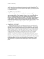
This manual provides commissioning, operating, and troubleshooting instructions for
Milnor® washer-extractors in the TxE model line, which are equipped with the Milnor®
electronic timer control. See the installation manual for information on machine installation
procedures and mechanical requirements. See the service manual for preventive maintenance,
service procedures, and mechanical parts identification. See the schematic manual for electrical
parts identification and electrical troubleshooting instructions.
i. 2.
How To Identify This Manual and Its Included Documents [Document
BIUUUD13]
A complete identification of this manual or any document in this manual must include all
specifications shown on the front cover, as defined below:
Published manual number—Primary identification number for the manual or any variation of it.
Specified date—The approximate date of introduction of the product or product change this
manual covers.
As-of date—When a manual for an old product is generated, any new information about the old
product developed up to this date will be included in the manual.
Access date—The date the manual was generated (assembled and formatted).
Applicability—Code(s) that represent a group of machines this manual applies to and/or actual
model numbers of applicable machines. The complete list of applicable models is provided
inside the front cover.
When referring to any document used in this manual (as identified by an eight-character
document number such as BIUUUD13 at the start of the document), a complete identification of
the document must include all specifications shown on the front cover, except substituting the
document number for the published manual number.
i. 3.
Trademarks of Pellerin Milnor Corporation [Document BIUUUD14]
The following, some of which may be used in this publication, are trademarks of Pellerin
Milnor Corporation:
PELLERIN MILNOR CORPORATION
Preface
Table1: Trademarks
Ampsaver®
Autolint®
Auto-Purge®
Autovac
CBW®
Dye-Extractor®
Dyextractor®
E-P Express®
E-P OneTouch®
E-P Plus®
Gear Guardian®
Hands-Off®
Hydro-Cushion®
Mentor™
Mildata®
— End of BICEUK01 —
PELLERIN MILNOR CORPORATION
Milnet®
Milnor®
Miltrac
Miltron
Staph-Guard®
System 4®
System 7®
Totaltrol
Table of Contents
Contents
Sections
Figures, Tables, and Supplements
Preface
i. About This Manual (Document BICEUK01)
i.1.
Scope
i.2.
How To Identify This Manual and Its Included Documents
(Document BIUUUD13)
i.3.
Trademarks of Pellerin Milnor Corporation
(Document
BIUUUD14)
Table 1: Trademarks
Table of Contents
Chapter 1. Commissioning
1.1.
1.1.1.
1.1.2.
Important Owner/User Information (Document BICEUK02)
Ensure Safety of All Laundry Personnel
Customize the Machine Controller
1.2.
About the Forces Transmitted by Milnor® Washerextractors (Document BIWUUI02)
Foundation Considerations
How Strong and Rigid?
1.2.1.
1.2.2.
1.3.
Figure 1: How Rotating Forces Act on the
Foundation
Important Instructions for Pumped Chemical Inlets
(Document BIWUUI01)
1.3.1.
1.3.2.
1.3.3.
1.4.
How Pumped Chemical Systems Can Internally Damage Supplement 1: Preventing Dribbling by
the Washer-extractor
Purging Chemical Lines
Locating Chemical System Components to Reduce the
Figure 2: Proper Routing of Chemical
Risk of Internal Damage
Tubing
Preventing Leaks Which Can Injure Personnel and Cause Figure 3: Liquid Supply Injection Port
External Damage
Electrical Connections for Liquid Chemical Systems
(Document BICEUI01)
1.4.1.
Pump Signal Connections
1.4.2.
Timer Stop Connections
1.5.
1.5.1.
Formulas in Milnor® TxE Electronic Timer Washerextractors (Document BICEUP01)
Hotel and Hospitality Configuration
Supplement 2: Maximizing Chemical
Injection Precision
Table 2: Chemical Injection Signals for
TxE Models
Figure 4: Pump Signal Connections
Table 3: Hotel and Hospitality Formula
Set 1
Table 4: Hotel and Hospitality Formula
Set 2
PELLERIN MILNOR CORPORATION
Table of Contents
Sections
1.5.2.
Figures, Tables, and Supplements
Healthcare Configuration
Table 5: Healthcare Formula Set 1
Table 6: Healthcare Formula Set 2
Chapter 2. Configuring
2.1.
Configuring TxE Washer-extractor Models
(Document
BICEUC01)
2.1.1.
Is this switch position ON or OFF?
2.1.2.
2.1.2.1.
2.1.2.2.
2.1.2.3.
2.1.2.4.
Configuration decisions
Selecting the Formula Set
Split water for final rinse
Switch positions not used
Normal and diagnostic mode selection
Figure 5: Microprocessor board and DIP
switch
Chapter 3. Operating
3.1.
3.2.
Determining Load Size
(Document BIWUUO01)
Controls on TxE Model Washer-extractors
(Document
BICEUF01)
3.2.1.
Control Functions During Normal Operation
Formula Selection Buttons
3.2.1.1.
Terminate Button
3.2.1.2.
Last Rinse Light
3.2.1.3.
In Progress Light
3.2.1.4.
Door Unlock Button
3.2.1.5.
3.2.2.
Control Functions During Testing
Formula Selection Buttons
3.2.2.1.
Formula A button (")
3.2.2.1.1.
Formula B button (<)
3.2.2.1.2.
Formula C button (>)
3.2.2.1.3.
Formula D button (?)
3.2.2.1.4.
Terminate Button
3.2.2.2.
Last Rinse Light
3.2.2.3.
In Progress Light
3.2.2.4.
Door Unlock Button
3.2.2.5.
3.3.
E-timer Operation (Document BICEUO01)
3.3.1.
Instructions for Normal Operation
3.3.1.1.
Load the Machine
3.3.1.2.
Start a Formula
3.3.1.2.1.
After a Completed Formula (Normal)
3.3.1.2.2.
After Opening the Door during a Formula
3.3.1.3.
Unload the Machine
PELLERIN MILNOR CORPORATION
Figure 6: TxE Controls
Table of Contents
Sections
3.3.2.
Figures, Tables, and Supplements
How to End a Formula Early
Chapter 4. Testing and Troubleshooting
4.1.
4.1.1.
4.1.2.
4.1.3.
Troubleshooting Errors (Document BICEUT03)
Vibration Switch Tripped
Door Open
Inverter Fault
4.2.
Testing TxE Washer-extractors (Document BICEUT02)
4.2.1.
Testing without the Display Kit
4.2.2.
Testing with the Display Kit
4.2.2.1.
Connecting the Display
4.2.2.2.
4.2.2.2.1.
4.2.2.2.2.
4.2.2.2.3.
4.2.2.3.
4.2.2.3.1.
4.2.2.3.2.
4.2.2.3.3.
Displays in Run Mode
Timer Display
Inputs Display
Outputs Display
Displays in Test Mode
Setting the DIP Switch for Test Mode
Figure 7: Microprocessor Controller
Components
Table 7: TxE Inputs
Table 8: TxE Outputs
Figure 8: Selecting Test Mode on DIP
Switch SW1
Interpreting the Display
Viewing Inputs
Figure 9: Level Switch Testing
4.2.2.3.4.
Testing Outputs
4.3.
TxE Event Timing (Document BICEUF02)
4.3.1.
Hotel and Hospitality Software
4.3.1.1.
Formula Set 1
4.3.1.2.
4.3.2.
Formula Set 2
Table 9: Events for Hotel and Hospitality
Set 1, Formula A
Table 10: Events for Hotel and Hospitality
Set 1, Formula B
Table 11: Events for Hotel and Hospitality
Set 1, Formula C
Table 12: Events for Hotel and Hospitality
Set 1, Formula D
Table 13: Events for Hotel and Hospitality
Set 2, Formula A
Table 14: Events for Hotel and Hospitality
Set 2, Formula B
Table 15: Events for Hotel and Hospitality
Set 2, Formula C
Table 16: Events for Hotel and Hospitality
Set 2, Formula D
Healthcare Software
PELLERIN MILNOR CORPORATION
Table of Contents
Sections
4.3.2.1.
Formula Set 1
4.3.2.2.
Formula Set 2
PELLERIN MILNOR CORPORATION
Figures, Tables, and Supplements
Table 17: Events for Healthcare Set 1,
Formula A
Table 18: Events for Healthcare Set 1,
Formula B
Table 19: Events for Healthcare Set 1,
Formula C
Table 20: Events for Healthcare Set 1,
Formula D
Table 21: Events for Healthcare Set 2,
Formula A
Table 22: Events for Healthcare Set 2,
Formula B
Table 23: Events for Healthcare Set 2,
Formula C
Table 24: Events for Healthcare Set 2,
Formula D
Chapter 1. Commissioning
Chapter 1
Commissioning
1.1. Important Owner/User Information
Document ............. BICEUK02
Spec Date ................ 20010122
As-of Date ............... 20010122
The following two procedures must be completed before this machine is placed in service:
1. Ensure the safety of all laundry personnel.
2. Customize the machine controller for the intended machine application.
1.1.1.
Ensure Safety of All Laundry Personnel
Ensure that all personnel who will operate or maintain this machine read the safety manual
before permitting them to access the machine. Ensure that all user manuals are available to the
appropriate personnel and that all precautions explained in all applicable manuals are observed.
1.1.2.
Customize the Machine Controller
Customizing the controller includes verifying that it is configured for the particular
application (set of four pre-programmed formulas) for which the machine will be used. Always
verify the machine configuration when the machine is first placed in service and after replacing
the microprocessor controller.
Configure this machine for its intended purpose by setting DIP switch SW1 on the
microprocessor controller. See the table of contents for this manual for the location of detailed
configuration instructions.
— End of BICEUK02 —
1.2. About the Forces Transmitted by Milnor®
Washer-extractors
Document ............. BIWUUI02
Spec Date ................ 20010122
As-of Date ............... 20010122
During washing and extracting, all washer-extractors transmit both static and dynamic
(cyclic) forces to the floor, foundation, or any other supporting structure. During washing, the
impact of the goods as they drop imparts forces which are quite difficult to quantify. Size for size,
both rigid and flexibly-mounted machines transmit approximately the same forces during
washing. During extracting, rigid machines transmit forces up to 30 times greater than equivalent
flexibly-mounted models. The actual magnitude of these forces vary according to several factors:
•
•
•
•
•
machine size,
final extraction speed,
amount, condition, and type of goods being processed,
the liquor level and chemical conditions in the bath preceding extraction, and
other miscellaneous factors.
PELLERIN MILNOR CORPORATION
Chapter 1. Commissioning
Estimates of the maximum force normally encountered are available for each Milnor® model
and size upon request. Floor or foundation sizes shown on any Milnor® document are only for
on-grade situations based only on previous experience without implying any warranty, obligation,
or responsibility on our part.
1.2.1.
Foundation Considerations
Size for size, rigid washer-extractors naturally require a stronger, more rigid floor,
foundation, or other supporting structure than flexibly-mounted models. If the supporting soil
under the slab is itself strong and rigid enough and has not subsided to leave the floor slab
suspended without support, on grade installations can often be made directly to an existing floor
slab if it has enough strength and rigidity to safely withstand our published forces without
transmitting undue vibration. If the subsoil has subsided, or if the floor slab itself has insufficient
strength and rigidity, a deeper foundation, poured as to become monolithic with the floor slab,
may be required. Support pilings may even be required if the subsoil itself is “springy” (i.e., if its
resonant frequency is near the operating speed of the machine). Above-grade installations of rigid
machines also require a sufficiently strong and rigid floor or other supporting structure as
described below.
1.2.2.
How Strong and Rigid?
Many building codes in the U.S.A. specify that laundry floors must have a minimum live
load capacity of 150 pounds per square foot (732 kilograms per square meter). However, even
compliance with this or any other standard does not necessarily guarantee sufficient rigidity. In
any event, it is the sole responsibility of the owner/user to assure that the floor and/or any other
supporting structure exceeds not only all applicable building codes, but also that the floor and/or
any other supporting structure for each washer-extractor or group of washer-extractors actually
has sufficient strength and rigidity, plus a reasonable factor of safety for both, to support the
weight of all the fully loaded machine(s) including the weight of the water and goods, and
including the published 360º rotating sinusoidal RMS forces that are transmitted by the
machine(s). Moreover, the floor, foundation, or other supporting structure must have sufficient
rigidity (i.e., a natural or resonant frequency many times greater than the machine speed with a
reasonable factor of safety); otherwise, the mentioned 360º rotating sinusoidal RMS forces can be
multiplied and magnified many times. It is especially important to consider all potential vibration
problems that might occur due to all possible combinations of forcing frequencies (rotating
speeds) of the machine(s) compared to the natural frequencies of the floor and/or any other
supporting structure(s). A qualified soil and/or structural engineer must be engaged for this
purpose.
PELLERIN MILNOR CORPORATION
Chapter 1. Commissioning
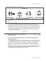
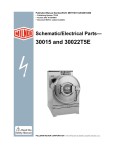
Figure 1: How Rotating Forces Act on the Foundation
Typical Machine
Legend
A.
B.
C.
Direction of force
Load
Rotation (Frequency = RPM / 60)
Figure 1 above is intended to depict both on-grade and above-grade installations and is
equally applicable to flexibly-mounted washer-extractors, as well as to rigid models installed
either directly on a floor slab or on a foundation poured integrally with the slab. Current machine
data is available from Milnor® upon request. All data is subject to change without notice and may
have changed since last printed. It is the sole responsibility of every potential owner to obtain
written confirmation that any data furnished by Milnor® applies for the model(s) and serial
number(s) of the specific machines.
— End of BIWUUI02 —
1.3. Important Instructions for Pumped
Chemical Inlets
1.3.1.
Document ............. BIWUUI01
Spec Date ................ 20010122
As-of Date ............... 20010122
How Pumped Chemical Systems Can Internally Damage the
Washer-extractor
Many pumped liquid chemical systems dribble concentrated chemicals out of the injection
tubes when the system is not used for relatively long periods of time—as after working hours and
during weekends. This puts highly concentrated corrosive chemicals in direct contact with dry
stainless steel surfaces, and often directly on any textiles left in the machine. Chemical
deterioration (rusting) of the stainless steel and damage to the textiles is the inevitable
result.
Pellerin Milnor Corporation accepts absolutely no responsibility whatsoever for damage to
its equipment or to any textiles therein when concentrated chemicals dribble out of the
injection tubes onto any part of the machine or its contents.
PELLERIN MILNOR CORPORATION
Chapter 1. Commissioning
Supplemental Topic 1
Preventing Dribbling by Purging Chemical Lines
Although the injection site is flushed by washer agitation on some models and after each
injection on other models to aid the injection process, this flushing provides absolutely no
protection against harmful dribble which occurs later—when the machine is no longer in use.
One foolproof solution for “dribbling” is to completely purge the appropriate chemical
injection tube with fresh water after every injection, so that only fresh water (which cannot
cause a problem) can dribble out.
Obviously, it is the sole responsibility of the pump and/or chemical supplier (not the
machine manufacturer) to furnish such a flushing device. (We understand that such flushing
type chemical injection systems—both for retrofit to existing systems and for new
installations—are now offered by others.)
1.3.2.
Locating Chemical System Components to Reduce the Risk of
Internal Damage
If the tubes, pumps, and chemical tanks are kept well below the injection point, the
likelihood of “after-hours dribbling” is reduced, but not totally eliminated.
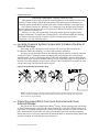
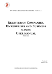
We therefore urge that tubes from any non-flushing pumped chemical system be connected
as shown in Figure 2. Although fresh-water flushing the just-used tubes after each injection
would be better, we believe routing the tubes as indicated will probably minimize the dribbling
effect about as much as possible without flushing. Never permit tanks, pumps, or any portion of
the tubes to be higher than the injection point. If loops in the injection tubes are employed, make
sure the entire loop is well below the injection point.
Figure 2: Proper Routing of Chemical Tubing
Note 1: As shown in Figure 2, all tanks, pumps, and tubing must be lower than the injection point on the
machine and must not dribble chemicals into the machine, nor leak chemicals externally onto any portion
of the machine or its surroundings.
1.3.3.
Preventing Leaks Which Can Injure Personnel and Cause
External Damage
All ports on the inlet are plugged at the Milnor® factory. When replacing plugs with fittings
or when reinstalling plugs, always use the sealant furnished (LocTite RTV Silicone Adhesive or
equivalent). Use properly sized hose barbs, always use clamps, and check for leaks. Use the hose
barbs furnished with your machine only if they provide the proper fit for the tubes employed.
Ensure that excessive pressures cannot build up that might burst or disconnect tubing. Instruct the
operator to monitor for leaks and report any occurences.
PELLERIN MILNOR CORPORATION
Chapter 1. Commissioning
When calibrating injections, it is permissible to remove tubes from barbed fittings to take
samples. However, always check for leaks after installing tubes and clamps. A preferable method
is to install a three-way or two two-way valves onto each injection tube for sampling.
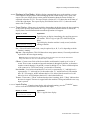
Warning 1 : Avoid chemical burns and corrosion—Concentrated liquid
chemicals leaking from a chemical system can burn skin and eyes, cause other types of
injury or illness, and corrode machine components.
• Ensure that excessive pressures cannot build up which might burst or disconnect a
chemical delivery tube.
• Ensure that there are no external chemical leaks when the system is installed or
calibrated.
• Periodically check the system for leaks during operation.
Caution 2 : Avoid corrosion and textile damage—Chemicals dribbling into the
machine when it is idle will corrode machine components and damage any textiles left
in the machine.
• If possible, use a system that flushes the entire chemical delivery tube after each
injection.
• If a non-flushing system is used, install tanks, pumps, and tubing below the injection
point on the machine, such that chemicals travel to the machine at an upward angle.
Caution 3 : Avoid explosions—Certain chemicals will react when combined.
• Connect chemical tubing so that bleach and sour inlets are as far apart as possible.
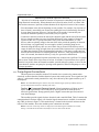
Figure 3: Liquid Supply Injection Port
Figure
Legend
A.
B.
C.
D.
Machine shell
Removeable plug
Chemical injection
housing
Toward front of machine
Notice 4 : Pellerin Milnor Corporation accepts absolutely no responsibility for
damage to its equipment or to any textiles therein when concentrated chemicals
dribble out of the injection tubes onto any part of the machine or its contents.
— End of BIWUUI01 —
PELLERIN MILNOR CORPORATION
Chapter 1. Commissioning
1.4. Electrical Connections for Liquid Chemical
Systems
Document ............... BICEUI01
Spec Date ................ 20010122
As-of Date ............... 20010122
Warning 5 : Electric Shock Hazard—Contact with high voltage electricity will
kill or seriously injure you. Even when the machine is not running, three-phase power
and control circuit power are still present at several locations within the cabinet and at
some electrical components.
Caution 6 : Injury and Damage Hazards—Improper wiring can cause the
machine to malfunction, risking injury to personnel, damage to machine components,
and damage to goods.
• Electrical and piping connections described in this section must be made only by
qualified, authorized personnel.
• Lock off and tag out power at the external disconnect switches for the washerextractor before proceeding.
• Do not rely merely on the information in this section when wiring. Consult all
applicable electrical schematics.
• Do not reroute or rearrange any wires not specifically permitted by this instruction.
• Do not connect a common wire to ground. Use the common terminal furnished.
Caution 7 : Risk of Poor or Inconsistent Wash Quality—Injection times of
less than 10 seconds are discouraged because fine adjustments are not possible, and
factors such as pump lag time may cause significant variations in the amount of
chemical delivered.
• Size pumps or valves small enough for adequate control (i.e., for longer injection
times).
• Use two pumps or valves to inject a small or large quantity of the same chemical, if
required.
PELLERIN MILNOR CORPORATION
Chapter 1. Commissioning
Supplemental Topic 2
Maximizing Chemical Injection Precision
Injection of a consistent amount of chemical is important in controlling wash quality and
using chemicals economically. When chemicals are injected by units of time, as is done with
most washer-extractors, injections of short duration can be imprecise because of two reasons:
• Fine adjustments to the delivered quantity are not possible. For example, if an injection of
three seconds is extended by one second, the quantity delivered is theoretically increased
by more than 30 percent. However, if an injection of 20 seconds is increased by one
second, the theoretical quantity is increased by only five percent.
• Variations in the time between the start of the chemical signal and the start of the chemical
delivery into the machine can cause significant differences in the quantity of chemical
injected. In this case, if a pump starts more slowly some times than others, or if the
delivery tubes are partially empty at the start of the inject period, the quantity of chemical
delivered may vary significantly. As an example, assume a peristaltic pump moves
chemical along the delivery tube at a rate of three feet per second. If the delivery tube is
empty for three feet along its length, then one second of the injection time is spent injecting
air rather than chemical. If the programmed injection time is only three seconds, then one
third of the desired chemical is not being delivered. However, if the programmed injection
time is 20 seconds, the chemical delivery is only five percent less than desired.
Increasing the programmed injection time makes any variation less significant. Use pumps
and/or valves sized to allow inject times of at least 10 seconds. If injection times for a specific
chemical vary widely from one formula to another, consider using two pumps or valves for the
same chemical. Actuate one pump for injecting small quantities, and use both pumps or valves
for larger quantities.
1.4.1.
Pump Signal Connections
The microprocessor controller used on TxE models closes certain relay contacts when
chemicals are desired and to flush the chemical system after each injection. These signals are 240
volts AC, and cannot be made potential-free. Any device driven by this signal can draw up to 37
milliamperes.
Note 2: The manifold flush signal is effective only if the chemical supply system (provided by others) is
properly designed and connected to a flushing water source.
Caution 8 : Component Damage Hazard—Board components will burn out and
require board replacement if devices driven by inject signals do not meet the above
electrical specifications. Pumps generally draw a higher current than specified, and will
cause board damage.
This machine provides signals for three chemicals and a manifold flush. Table 2 contains the
connection details for these signals. All chemical signal connections are available in on terminal
strip TBS, as shown in Figure 4. This terminal strip is located in the electrical enclosure on the
left rear of the machine, where the machine power connections are made.
Note 3: Unless the “Timer Stop” feature is employed, each chemical signal is enabled for 30 seconds,
starting 15 seconds after the desired level (usually low level) is achieved for the bath.
PELLERIN MILNOR CORPORATION
Chapter 1. Commissioning
Table2: Chemical Injection Signals for TxE Models
Signal
Component
Chemical 1
Chemical 2
Chemical 3
Manifold Flush
Chemical
Relay
Processor Board
Connection
TBS Terminal
Number
Detergent
Bleach
Finishing
chemicals
none
K13
K14
MTA6-7,8
MTA6-3,4
1
2
K15
MTA6-1,2
3
K12
MTA7-1,2
4
Figure 4: Pump Signal Connections
Electrical Connections Enclosure
Legend
A.
B.
C.
D.
E.
F.
1.4.2.
Timer Stop Connections
Detergent signal
Bleach signal
Sour and starch/softener
signal
Manifold flush signal
Chemical signal common
Machine power
connections
“Timer stop” is a feature of the TxE control which stops the machine timer while a certain
input to the microprocessor is grounded. When multiple machines without this feature are
connected to a common chemical supply system, the quantity of chemical injected can vary
widely if two or more machines request chemical simultaneously. When properly wired, the
chemical supply system stops the timers in certain linked machines when one machine requests
PELLERIN MILNOR CORPORATION
Chapter 1. Commissioning
chemical. When the chemical injection is completed, the chemical supply system terminates the
timer stop command, and the stopped timers resume counting.
When the timer in a machine is stopped, the current formula event continues until the timer
resumes counting. If water valves are open when the timer stops, they will close when the desired
level is reached. Chemical injection signals will stop after the designated time, but the manifold
flush signal will not occur until the timer starts. All other actions (cylinder reversing, extract
speed, drain speed, etc.) that are in progress when the timer is stopped will continue until the
timer starts again and the programmed time for the current event expires.
Milnor provides two wires terminated with butt connectors in the rear console of the
machine. One wire originates electrically from pin 4 of MTA7 on the processor board. The other
wire is electrically identical to pin 6 of MTS1 on the switch panel board. For timer stop to
function, the chemical system should include a normally open contact between these two
connectors. When the contact is open, the machine runs normally. When the contact is closed, the
machine timer stops.
— End of BICEUI01 —
1.5. Formulas in Milnor® TxE Electronic Timer
Washer-extractors
Document .............. BICEUP01
Spec Date ................ 20010122
As-of Date ............... 20010122
This section describes the formulas provided in your washer-extractor with the Milnor®
electronic timer controller. For each configuration, the table shows each step in the four available
formulas.
Two software chips are available for these machines: hotel and hospitality, and healthcare.
Your machine was shipped from the Milnor factory with the chip set specified when the machine
was ordered. Contact the factory to purchase the chip necessary to change the machine from one
industry to another.
Note 4: Because plant water pressure influences the time required for the machine to fill, the run times
stated in the tables below do not include machine fill times.
Note 5: Drain and coast times are subject to change without notice.
Note 6: Certain chemical supply systems may actuate an input to the microprocessor which stops the
formula timer. This action increases the total time required for the formula to complete, but does not affect
the elapsed time.
PELLERIN MILNOR CORPORATION
Chapter 1. Commissioning
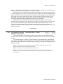
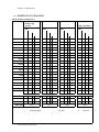
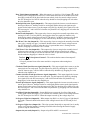
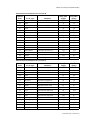
1.5.1.
Hotel and Hospitality Configuration
Table3: Hotel and Hospitality Formula Set 1
Operation
Formula A:
Blankets and
Spreads
Formula B: Sheets
Formula C: Towels
Formula D: White
Heavy Soil
Time
Time
Time
Time
Chemicals
Temp
Level
Chemicals
Temp
Level
Chemicals
Temp
Level
Chemicals
Temp
Level
Flush
2
S Hi
Drain
1.25
Bath 8
D S Lo
10 DB H Lo
7
D H Lo
10 D H Lo
Drain 1.25
1.25
1.25
1.25
Rinse 2
S
Hi
2
H Hi
Drain 1.25
1.25
Bath
7
B H Lo
7
B H Lo
Drain
1.25
1.25
Rinse 2
C Hi
2
H Hi
2
H Hi
Drain 1.25
1.25
1.25
Extract
1
1
1
Coast
1.25
1.25
1.25
Rinse
2
2
S
Hi
2
S Hi
Drain
1.25
1.25
1.25
Extract
1
1
1
Coast
1.25
1.25
1.25
Bath 4
F C Lo
4
F C Lo
4
F C Lo
4
F C Lo
Note: A DIP switch setting allows configuring this operation for split fill.
Drain 1.25
1.25
1.25
1.25
Extract 7
6
7
7
Coast 1.25
1.25
1.25
1.25
Run Time
29.25
34.75
41.0
47.25
Key to Abbreviations:
D
Usually detergent
H
Hot water
Hi High level
B
Usually bleach
C
Cold water
Lo Low level
F
Sour/softener or sour/starch
S
Split water
Notes:
1
For any bath step, the timer does not run until the desired level is achieved.
PELLERIN MILNOR CORPORATION
Chapter 1. Commissioning
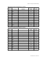
Table4: Hotel and Hospitality Formula Set 2
Operation
Formula A:
Colored 100% Poly
Table Linen
Formula B: White
100% Poly Table
Linen
Formula C: Stain
Treatment
Formula D: White
Kitchen Goods
Time
Time
Time
Time
Chemicals
Temp
Level
Chemicals
Temp
Level
Chemicals
Temp
Level
Chemicals
Temp
Level
Bath 10 D H Lo
10 D H Lo
20 DB H Lo
5
D H Lo
Carryover
1
H Hi
Drain 1.25
1.25
1.25
1.25
Rinse
2
H Hi
Drain
1.25
Bath
7
B H Lo
8
D H Lo
Drain
1.25
1.25
Rinse 2
S
Hi
2
S
Hi
2
H Hi
2
H Hi
Drain 1.25
1.25
1.25
1.25
Bath
7
B H Lo
Drain
1.25
Rinse 2
S
Hi
2
S
Hi
2
S
Hi
2
S Hi
Drain 1.25
1.25
1.25
1.25
Extract
1
1
Coast
1.25
1.25
Rinse
2
S
Hi
2
S Hi
Drain
1.25
Bath 4
F C Lo
4
F C Lo
4
F C Lo
Note: A DIP switch setting allows configuring this operation for split fill.
Drain 1.25
1.25
1.25
1.25
Extract 2.5
2.5
7
7
Coast 1.25
1.25
1.25
1.25
Run Time
30.0
35.0
44.75
50.25
Key to Abbreviations:
D
Usually detergent
H
Hot water
Hi High level
B
Usually bleach
C
Cold water
Lo Low level
F
Sour/softener or sour/starch
S
Split water
Notes:
1
For any bath step, the timer does not run until the desired level is achieved.
PELLERIN MILNOR CORPORATION
Chapter 1. Commissioning
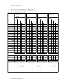
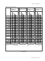
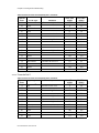
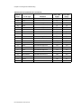
1.5.2.
Healthcare Configuration
Table5: Healthcare Formula Set 1
Operation
Formula A:
Blankets and
Spreads
Formula B: Sheets
Formula C: Towels
Formula D:
Diapers and Pads
Time
Time
Time
Time
Chemicals
Temp
Level
Chemicals
Temp
Level
Chemicals
Temp
Level
Chemicals
Temp
Level
Flush
2
S
Hi
2
S
Hi
3
S Hi
Drain
1.25
1.25
1.25
Bath 8
D S Lo
Flush
2
S
Hi
2
S
Hi
2
S Hi
Drain 1.25
1.25
1.25
1.25
Flush
2
S Hi
Rinse 2
S
Hi
Drain 1.25
1.25
Bath
7
D H Lo
7
D H Lo
7
D H Lo
Drain
1.25
1.25
Carryover
1
H Hi
Rinse 2
C Hi
2
H Hi
Drain 1.25
1.25
1.25
Bath
7
B H Lo
7
B H Lo
7
B H Lo
Drain
1.25
1.25
1.25
Rinse
2
S
Hi
2
S
Hi
2
S Hi
Drain
1.25
1.25
1.25
Rinse
2
S
Hi
2
S
Hi
2
S Hi
Drain
1.25
1.25
1.25
Bath 4
F C Lo
4
F C Lo
4
F C Lo
4
F C Lo
Note: A DIP switch setting allows configuring this operation for split fill.
Drain 1.25
1.25
1.25
1.25
Extract 7
6
7
7
Coast 1.25
1.25
1.25
1.25
Run Time
29.25
34.75
44.00
50.50
Key to Abbreviations:
D
Usually detergent
H
Hot water
Hi High level
B
Usually bleach
C
Cold water
Lo Low level
F
Sour/softener or sour/starch
S
Split water
Notes:
1
For any bath step, the timer does not run until the desired level is achieved.
PELLERIN MILNOR CORPORATION
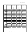
Chapter 1. Commissioning
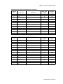
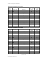
Table6: Healthcare Formula Set 2
Operation
Formula A:
Personal Goods
Formula B: White
100% Poly Table
Linen
Formula C: Stain
Treatment
Formula D: White
Heavy Soil
Time
Time
Time
Time
Chemicals
Temp
Level
Chemicals
Temp
Level
Chemicals
Temp
Level
Chemicals
Temp
Level
Flush 2
S
Hi
2
S Hi
Drain 1.25
1.25
Bath 7
D H Lo
10 D H Lo
20 DB H Lo
10 D H Lo
Drain 1.25
1.25
1.25
1.25
Rinse 2
H Hi
2
H Hi
Drain 1.25
1.25
Bath
7
B H Lo
7
B H Lo
Drain
1.25
1.25
Rinse 2
S
Hi
2
S
Hi
2
H Hi
2
H Hi
Drain 1.25
1.25
1.25
1.25
Extract
1
Coast
1.25
Rinse 2
S
Hi
2
S
Hi
2
S
Hi
2
S Hi
Drain 1.25
1.25
1.25
1.25
Extract
1
1
Coast
1.25
1.25
Bath 4
F C Lo
4
F C Lo
2
C Hi
4
F C Lo
Note: A DIP switch setting allows configuring this operation for split fill.
Drain 1.25
1.25
1.25
1.25
Extract 6
2.5
7
7
Coast 1.25
1.25
1.25
1.25
Run Time
33.75
35.0
44.75
47.25
Key to Abbreviations:
D
Usually detergent
H
Hot water
Hi High level
B
Usually bleach
C
Cold water
Lo Low level
F
Sour/softener or sour/starch
S
Split water
Notes:
1
For any bath step, the timer does not run until the desired level is achieved.
— End of BICEUP01 —
PELLERIN MILNOR CORPORATION
Chapter 2. Configuring
Chapter 2
Configuring
2.1. Configuring TxE Washer-extractor Models
Document ..............BICEUC01
Spec Date ................ 20010122
As-of Date ............... 20010122
Because the microprocessor that controls your machine during normal operation is also
capable of other functions, it must be configured for your specific machine. Configuration
information is controlled by a group of small switches (together called a DIP switch) on the
processor board. When power is first applied to the machine, the microprocessor reads the on or
off status of each of the DIP switch positions.
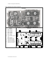
2.1.1.
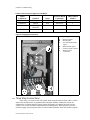
Is this switch position ON or OFF?
You can set each of the eight DIP switch positions to on or off. Turn any switch position off
by pressing down on the side nearest the word “OFF.” Turn the switch position on by pressing
down on the side nearest the number. Use a pencil or a stiff wire to set the switch; it will click
into position when pressed far enough. See Figure 5 for the DIP switch location.
PELLERIN MILNOR CORPORATION
Chapter 2. Configuring
Figure 5: Microprocessor board and DIP switch
Graphic
Legend
A.
B.
C.
D.
E.
Processor board
Typical DIP switch
(detail)
Position 3 OFF (example)
Position 1 ON (example)
Software version label on
EPROM
PELLERIN MILNOR CORPORATION
Chapter 2. Configuring
2.1.2.
Configuration decisions
2.1.2.1.
Selecting the Formula Set—DIP switch position 1 determines the formula set used. Set
this switch position on (press the side nearest the number down) to configure the machine for the
four primary formulas. Set this switch off (press the side nearest the word “OFF” down) to use the
secondary set of formulas. The available formulas are listed in “Formulas in Milnor TxE
Electronic Timer Washer-extractors” (see the table of contents).
2.1.2.2.
Split water for final rinse—In some locations the temperature of the incoming cold water
may be too cold to allow the proper activation of softener chemicals. In these locations, turn
switch position 2 off (press the side nearest the word “OFF” down) to cause both water valves to
open for all sour/softener steps.
2.1.2.3.
Switch positions not used—Switch positions 3, 4, 5, 6, and 7 are not used. These
positions have no effect on the operation of the machine.
2.1.2.4.
Normal and diagnostic mode selection—Switch position 8 determines whether the
machine is configured for normal operation or for diagnostics. With this position on, the machine
operates normally by running formulas.
When switch position 8 is off, the machine is configured for diagnostics. When switch
position 8 is off, connecting an optional display to the processor board aids in diagnosing
problems by allowing a qualified technician to manually actuate outputs individually.
— End of BICEUC01 —
PELLERIN MILNOR CORPORATION
Chapter 3. Operating
Chapter 3
Operating
Document ............BIWUUO01
Spec Date ................ 20010122
As-of Date ............... 20010122
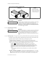
3.1. Determining Load Size
Putting too much linen into a properly designed laundry washer-extractor will not overload
the machine to its mechanical or electrical detriment if these guidelines are followed:
1. The goods consist of typical cotton and/or synthetic fabrics normally encountered in
commercial laundering operations.
2. The load is not so bulky as to prevent a reasonably balanced distribution prior to the onset of
extraction.
3. The extract speed has not been increased above the designed maximum.
4. The total number of intermediate and final extractions do not exceed the designed maximum
for the extract motor.
Thus, the maximum soiled linen capacity for any properly designed washer-extractor is
essentially limited by the amount of soiled goods that can actually be placed in the cylinder.
The maximum weight of soiled goods that a washer-extractor cylinder will accept depends
on the following factors:
• the internal volume of the cylinder (the space into which the goods can be placed), and
• the density (weight and bulkiness) of the specific goods
For example, many polyester-cotton fabrics have relatively low weights for their bulk so one
should rarely expect to be able to put in a published maximum capacity load of such fabrics. In
fact, published maximum capacities of machines based on the now generally accepted industry
standards will usually be achieved only with the highest density, closely woven fabrics and a
reasonable soil content.
The best load size depends on the size of the machine—plus the type of goods, soil content,
and wash quality desired. Since the latter factors vary considerably, prior experience and/or
experimentation generally yield the best results. Use these guidelines:
1. Overloading a washer-extractor will not increase production because longer wash formulas
and more rewash will be required.
2. Avoid underloads because the inevitable greater extraction imbalance will cause more extract
re-cycles and may stress the machine unnecessarily.
3. Load divided cylinder machines so that the weight in each compartment is approximately
equal at the onset of extraction. Do not put goods with grossly dissimilar water absorption
characteristics in the different compartments. Do not attempt to balance loads of wet goods in
one compartment against dry goods in the other.
— End of BIWUUO01 —
PELLERIN MILNOR CORPORATION
Chapter 3. Operating
3.2. Controls on TxE Model Washer-extractors
Document .............. BICEUF01
Spec Date ................ 20010122
As-of Date ............... 20010122
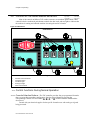
Most of the controls on Milnor® TxE washer-extractors are membrane push-buttons. Other
controls include a mechanical push-button to unlock the door latch, and two lights to indicate that
the machine is running and when the machine is nearing the end of a formula.
Figure 6: TxE Controls
Control Panel
Legend
A.
B.
C.
D.
E.
3.2.1.
3.2.1.1.
Formula Selection buttons
Terminate button
Last Rinse light
In Progress light
Door Unlock button
Control Functions During Normal Operation
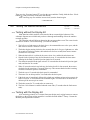
Formula Selection Buttons—The TxE controller provides four pre-programmed formulas
that vary according to machine configuration. Start the desired formula by pressing the
corresponding Formula Selection button (", <, >, or ?) with the machine loaded and the
door closed.
Consult with your chemical supplier for the specific formula to use with each type of goods
being processed.
PELLERIN MILNOR CORPORATION
Chapter 3. Operating
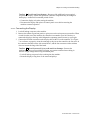
3.2.1.2.
Terminate Button—The Terminate button (z) ends any running formula. When a formula
is ended early, you must restart it from the beginning by pressing one of the the Formula
Selection buttons with the door closed.
3.2.1.3.
Last Rinse Light—This light comes on when the last bath step of any formula begins and
remains on until the formula ends. If the operator needs to add a chemical during the last bath,
such as softener, he should add it as soon as this light comes on. The Last Rinse light also alerts
the operator that the machine will soon be ready for unloading.
If an error occurs during a formula, this light and the In Progress light flash (two seconds on,
then two seconds off) for 10 minutes. After 10 minutes, both lights go off. The error can be a
malfunction of either the door lock circuit or the inverter. In either case, all machine controls are
locked out for 75 seconds to ensure that the cylinder has coasted to a stop. To open the door after
an error occurs, press the Terminate button (z) to clear the error condition, then hold the Door
Unlock button (') and press firmly on the door latch handle.
3.2.1.4.
In Progress Light—When power is first applied to the machine, this light flashes for 75
seconds to indicate that the power-up delay timer is counting down. The light goes off when the
power-up delay expires.
This light is constantly on when a formula starts (the door is closed and a formula selection
button is pressed). It remains on until the formula ends normally, is terminated by the operator, or
an error occurs.
If the formula ends normally by running to completion, the In Progress light goes off when
the last step of the formula ends. If the operator terminates a formula, this light flashes (two
seconds on, then two seconds off) for 75 seconds as the coast timer counts down. After 75
seconds, hold the Door Unlock button (') and press firmly on the door latch handle to open the
door.
3.2.1.5.
Door Unlock Button—This button activates a solenoid in the door latch which unlocks the
door latch handle, allowing the operator to open the door. To lessen the chance of injury caused
by opening the door while the basket is turning, the microprocessor controller disables this button
when a formula starts.
The Door Unlock button is disabled for 75 seconds after a formula ends, whether the
formula ended normally, was ended early by the operator, or ended because of an error.
3.2.2.
Control Functions During Testing
Do not attempt to test or troubleshoot a malfunctioning machine using only the information
in this document. For complete testing procedures, see “Testing TxE Washer-extractors” (see
table of contents).
The display kit referenced in Section 3.2.2.1 consists primarily of a vacuum fluorescent
display and a wiring harness to temporarily connect the display to the processor board for testing
by authorized, qualified technicians. This kit is available from Milnor.
PELLERIN MILNOR CORPORATION
Chapter 3. Operating
3.2.2.1.
3.2.2.1.1.
Formula Selection Buttons
Formula A button (")—With the display kit attached and the machine in normal operation
mode (DIP switch position 8 is on), this button stops the formula timer as long as it is held
depressed. The timer resumes running when the button is released. Hold this button to simulate
the timer stop feature. Timer stop is used by some chemical injection systems to postpone
chemical injection to a machine if the chemical system is already supplying chemical to another
machine on the same chemical supply manifold.
Display or Action
Explanation
F:A EQ:003 CE:000
Level A1/D1 T-Run
Typical display in normal operation mode before button " is
pressed.
F:A EQ:003 CE:000
Level A1/D1 T-Stop
Typical display in normal operation mode with button " held
depressed.
If the machine is in testing mode (DIP switch position 8 is off), this button makes input A on
the testing display and turns the next numerical output on. Holding " depressed causes the
controller to turn each output on for about one half second, then off before advancing
automatically and testing the next output in the sequence.
Note 7: For safety, the controller allows only one output to be turned on at a time in testing mode.
3.2.2.1.2.
Formula B button (<)—This button is ignored if the machine is in normal operation mode
and a formula is running. In testing mode, holding the Formula B button depressed makes input B
to the microprocessor.
Display or Action
ABCDEFGH
-+------
3.2.2.1.3.
Output #
00 is On
Explanation
Typical display in testing mode with button < held depressed.
Formula C button (>)—With the display kit attached and the machine in normal operation
mode (DIP switch position 8 is on), this button cycles the display through its three modes: timer
display, inputs display, and outputs display. Each display is fully described in “Testing TxE
Washer-extractors” in this manual. See the table of contents for the location of this document.
In testing mode (DIP switch position 8 is on), holding the Formula C button depressed
makes input C to the microprocessor.
Display or Action
ABCDEFGH
--+-----
3.2.2.1.4.
Output #
00 is On
Explanation
Typical display in testing mode with button > held depressed.
Formula D button (?)—This button is ignored if the machine is in normal operation mode
and a formula is running. In testing mode (DIP switch position 8 is off), holding the Formula D
button depressed makes input D to the microprocessor.
Display or Action
ABCDEFGH
---+----
Output #
00 is On
PELLERIN MILNOR CORPORATION
Explanation
Typical display in testing mode with button ? held depressed.
Chapter 3. Operating
3.2.2.2.
Terminate Button—In normal operation mode, this button terminates the formula in
progress. All controls are immediately locked out for a safety delay of 75 seconds.
In testing mode (DIP switch position 8 is off), the Terminate button provides input F to the
microprocessor.
3.2.2.3.
Last Rinse Light—In normal operation the Last Rinse light illuminates constantly from the
beginning of the last bath step (last rinse) until the formula ends, 75 seconds after the end of the
final extract step.
In testing mode (DIP switch position 8 is off), the Last Rinse light illuminates when output 8
is on.
3.2.2.4.
In Progress Light—In normal operation with the display attached, this light is illuminated
when output j is present.
Display or Action
abcdefghijklmnop
--+--+---+------
Explanation
Typical display during normal operation with the drain closed
(output c), the basket turning clockwise (output f), and the In
Progress light illuminated (output j).
In testing mode (DIP switch position 8 is off), the In Progress light illuminates when output
9 is on.
3.2.2.5.
Door Unlock Button—In normal operation with the display attached, this button is enabled
75 seconds after a formula ends for any reason. The door cannot be unlocked until the 75-second
safety delay expires. The safety delay also applies for 75 seconds after power is first applied to
the machine.
In testing mode (DIP switch position 8 is off), the Door Unlock button is energized only
when output 00 is on. With output 00 on, you should hear the door unlock when this button is
pressed.
— End of BICEUF01 —
3.3. E-timer Operation
3.3.1.
3.3.1.1.
Document ............. BICEUO01
Spec Date ................ 20010122
As-of Date ............... 20010122
Instructions for Normal Operation
Load the Machine
1. If the loading door is closed and latched, hold the Door Unlock button (') to unlock the
door while pressing firmly on the door latch handle with the other hand. If the door does not
unlock, verify that the machine is connected to power and that the wall disconnect is
functioning properly. The machine must have power available to unlock the door.
2. When the door opens, load the machine according to plant guidelines and “Determining Load
Size” (see table of contents).
3. Close the door firmly.
PELLERIN MILNOR CORPORATION
Chapter 3. Operating
3.3.1.2.
Start a Formula
3.3.1.2.1.
After a Completed Formula (Normal)—If the previous formula finished normally, simply
press the button that matches the formula you want to run. The selected formula will start
immediately if the door is closed. The Formula Running light (\) illuminates and the door locks
immediately, and the machine fills with water. Once the door is locked, the operator must end the
formula early (see Section 3.3.2) or wait for the formula to finish before opening the door.
3.3.1.2.2.
After Opening the Door during a Formula—If you ended the previous formula early by
opening the door, you must press the Terminate button (z) before you can start the machine
again. The Terminate button also clears any internal machine error that might have caused the
formula to end early.
3.3.1.3.
3.3.2.
Unload the Machine—When the formula ends, the Formula Running light (\) goes out.
Hold the Door Unlock button (') to unlock the door and press firmly on the door latch handle.
How to End a Formula Early
You can end any running formula by pressing the Terminate button (z) on the control
panel. A safety delay keeps the door locked for 75 seconds. When the In Progress light goes off,
hold the Door Unlock button (') to unlock the door and press firmly on the door latch handle.
To resume operation, restart the formula from the beginning by pressing the desired formula
button.
— End of BICEUO01 —
PELLERIN MILNOR CORPORATION
Chapter 4. Testing and Troubleshooting
Chapter 4
Testing and Troubleshooting
4.1. Troubleshooting Errors
4.1.1.
Document ..............BICEUT03
Spec Date ................ 20010122
As-of Date ............... 20010122
Vibration Switch Tripped
If the machine vibrates excessively during extract, the vibration switch (SMWVB in the
electrical schematics) closes to ground an input (MTA3-10) to the microprocessor. When the
machine is in an extract step and this input is grounded, the controller immediately ends the
extract step and starts the following coast step. The formula then continues normally.
Note 8: The vibration switch is physically located in the machine console, below the power supply. See
the document entitled “30015 and 30022T5E Component Location Details” in the schematic manual.
Note 9: The input which indicates that the vibration switch is tripped is shared with the high water level
pressure switch. Software determines whether to turn off the water valve(s) or to signal the inverter to stop
the motor depending on the step running when the input is grounded.
4.1.2.
Door Open
When the machine door is closed and the machine is operating normally, contacts 5 and 8 in
relay CRDL are closed, grounding the input on MTA3-7 to the microprocessor. If the door opens,
the input is lost. When the microprocessor loses the input, it signals an error and stops the
machine. For safety, all machine controls remain disabled for 75 seconds after the error occurs.
When this error occurs, the microprocessor signals the error by flashing both the In Progress
light and the Last Rinse light simultaneously. Both lights flash on for two seconds, then off for
two seconds, repeating for 10 minutes. After 10 minutes, both lights remain off.
To recover from this error, ensure that the door is securely closed, then start the formula
again.
4.1.3.
Inverter Fault
When operating normally, the inverter closes an internal contact wired in series with CRDL
pins 5 and 8. If the door is closed and the inverter is functioning, the input on MTA3-7 is
grounded, as described in Section 4.1.2. If the inverter senses a fault, its internal contacts open
and the input on MTA3-7 is lost. This same input is also lost if the door opens during operation.
Refer to the inverter documentation for specific troubleshooting procedures.
As happens when the door opens during a formula, the microprocessor signals the error by
flashing both the In Progress light and the Last Rinse light simultaneously. Both lights flash on
for two seconds, then off for two seconds, repeating for 10 minutes. After 10 minutes, both light
remain off.
For safety, all machine controls remain disabled for 75 seconds after the error occurs. To
open the door after this error, you must first wait the 75 seconds until the controls are enabled.
PELLERIN MILNOR CORPORATION
Chapter 4. Testing and Troubleshooting
Then press the Terminate button (z) to clear the error condition. Finally, hold the Door Unlock
button (') and press firmly on the door latch handle.
After correcting any error with the inverter itself, start the formula again.
— End of BICEUT03 —
4.2. Testing TxE Washer-extractors
4.2.1.
Document ..............BICEUT02
Spec Date ................ 20010122
As-of Date ............... 20010122
Testing without the Display Kit
Most functions of this machine can be tested with an accurate digital voltmeter if the
schematic diagrams are available and you have a thorough understanding of how the machine
normally operates.
The following rules will help you determine the current machine event. The events in each
formula are listed in “TxE Event Timing” (see table of contents).
1. The In Progress light turns on, the drain closes, the commanded water valves open, and the
door locks as soon as a formula is selected.
2. The basket begins rotating clockwise four seconds after the In Progress light turns on. After
20 seconds of clockwise rotation, the basket dwells for four seconds, then rotates counterclockwise for 20 seconds.
3. When the desired level is achieved, the water valves close and the formula timer runs.
4. Signals for the injection of any desired chemicals occur 15 seconds after the timer starts
counting for the bath. Chemical injection signals last 30 seconds.
5. The chemical manifold flush signal activates 15 seconds after the chemical injection signal
ends, and lasts for 30 seconds.
6. When 15 seconds remain in any bath step, the basket dwells for four seconds, then rotates
clockwise for the remaining 11 seconds of the step. This ensures that the basket is rotating
clockwise when drain speed is commanded.
7. The drain opens 15 seconds after drain speed is commanded.
8. The motor runs at drain speed for 30 seconds after the drain opens.
9. If the drain step is immediately followed by a bath step (without an intervening extract), the
basket coasts for 15 seconds before the next bath begins. The basket does not coast after a
drain step if the next step is an extract.
10. The basket coasts for 75 seconds after an extract step.
11. The Door Unlock button is enabled when the coast ends (75 seconds after the final extract
ends).
4.2.2.
Testing with the Display Kit
A kit consisting primarily of a vacuum fluorescent display and a wiring harness to connect
the display to the microprocessor controller is available from the Milnor® factory. Contact the
Milnor® parts department for details.
PELLERIN MILNOR CORPORATION
Chapter 4. Testing and Troubleshooting
Caution 9 : Avoid machine damage—Because of the additional power required
to operate the display, certain microprocessor controller components may be damaged if
the display is connected for extended periods of time.
• Connect the display only when testing the machine.
• Disconnect the display and replace all control panel covers before returning the
machine to normal operation.
4.2.2.1.
Connecting the Display
1. Lock off and tag out power to the machine.
2. Remove the cabinet top and rear panels to gain access to the microprocessor controller. When
viewed from the rear of the machine, the controller is mounted to your left. Don't try to
connect the display to the large white Magnetek component (motor inverter) to your right.
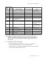
3. Connect the flat black connector on the display cable to MTA2 on the controller. Use Figure
7 as a reference to properly orient the connector to the pins on the controller; the four wires in
the connector should be on the side nearest MTA3, and the four connector sockets without
wires are nearest the long side of the board.
Caution 10 : Avoid personal injury and machine damage—Because the
machine must have power available for testing, use extreme caution when working in
the area of high voltage and moving mechanical parts.
• Lock off and tag out power before reaching into the machine.
• Route the display wiring clear of the motor and pulleys.
PELLERIN MILNOR CORPORATION
Chapter 4. Testing and Troubleshooting
Figure 7: Microprocessor Controller Components
Photograph
Legend
A.
B.
C.
D.
E.
F.
G.
H.
I.
J.
K.
L.
M.
N.
MTA2 (display)
MTA4 (outputs)
MTA5 (outputs)
MTA6 (outputs)
MTA7 (outputs)
MTA1 (power)
MTA3 (inputs)
Voltage regulator and heat
sink
Chassis ground
Micro-controller chip
Outputs K4 through K7
Outputs K0 through K3
Outputs K12 through K15
Outputs K8 through K11
PELLERIN MILNOR CORPORATION
Illustration
Chapter 4. Testing and Troubleshooting
4.2.2.2.
Displays in Run Mode—With the display connected and power to the machine, you can
select from three display modes without changing the DIP switch settings: timer, inputs, and
outputs. The timer display shows certain general information about the current formula, as
explained in Section 4.2.2.2.1. The inputs display (Section 4.2.2.2.2) shows the on/off status of
each of the eight inputs. The outputs display, described in Section 4.2.2.2.3, shows the on/off
status of the 16 outputs.
4.2.2.2.1.
Timer Display—When power is supplied to the machine, the display shows the time remaining
in the power-up safety delay and the In Progress light flashes.When a formula is started, the
display shows certain information about machine operation as it happens.
Display or Action
Explanation
Please Wait 74 Secs.
Typical power-up display immediately after applying power to
the machine. The In Progress light (\) flashes during the
delay.
F:x EQ:xxx CE:xxx
Level Ax/Dx T-Stop
Typical display when the machine is ready to run, but before
starting a formula.
F:x—Selected formula. In this field, x may be replaced by A, B, C, or D, depending on which
formula is running.
EQ:xxx—Elapsed quarters. This field shows how many quarter-minute (15-second) periods have
expired since the timer began running.
Note 10: Because the timer doesn't start running until the desired level is achieved, this field will not
change from 000 to 001 until 15 seconds after level is achieved.
CE:xxx—Current event. Each of the four available wash formulas is made up of a series of
events. These events are numbered upward continuously through all formulas, so formula A
contains events 0 through 9, formula B is events 10 through 23, etc. Tables with descriptions
of all events are in “TxE Event Timing” (see the table of contents).
Level Ax/Dx—Level achieved and desired. Low level is represented by “1,” and high level is
represented by “2.” Achieved level is the number after “A,” and desired level is the number
after “D.” For example, A0/D2 indicates that level 2 is desired, but the actual level is still
below low level. A2/D2 indicates that level 2 is desired and achieved.
T-xxxx—Timer status. “T-Run” indicates that the timer is running, while “T-Stop” indicates that
the timer is stopped. The timer is stopped while the machine is filling and when the timer stop
input is present.
4.2.2.2.2.
Inputs Display—From the timer display with a formula running, press the Formula C button
once to view the on/off status of the eight controller inputs.
Display or Action
F:C EQ:026 CE:024
Level A1/D1 T-Run
Explanation
This is a typical timer display.
PELLERIN MILNOR CORPORATION
Chapter 4. Testing and Troubleshooting
Display or Action
Explanation
>
Scrolls from the timer display to the inputs display.
This is a typical input status display during a bath with a
chemical. See Table 7 for the input that corresponds to each
character on the display. A plus sign (+) appears below each
active input; a minus sign (–) appears below each input that is
not present. In the example display to the left, inputs E and G are
present, indicating that the door is closed and low level is
achieved.
ABCDEFGH
----+-+-
Table7: TxE Inputs
Display
Letter
A
B
C
D
E
F
G
H
4.2.2.2.3.
Input Description
Formula A button depressed or
timer stop commanded
Formula B button depressed
Formula C button depressed
Formula D button depressed
Door is closed and inverter
functioning
Terminate button is depressed
Low level achieved
High level achieved or
vibration safety switch closed
Connector
and Pin
MTA3-1
Notes
Timer stops while button is depressed.
MTA3-2
MTA3-3
Can't be tested, but can be assumed functional
if you can view the inputs display.
MTA3-4
MTA3-7
MTA3-8
MTA3-9
MTA3-10
Input is lost when door opens or inverter faults
during a formula.
Testing terminates current formula.
Water valves close or controller terminates
extract step.
Outputs Display—From the inputs display, press the Formula C button once to view the on/off
status of the 16 controller outputs.
Display or Action
Explanation
This is a typical input status display during a flush or rinse bath.
ABCDEFGH
----+-++
>
abcdefghijklmnop
--+--+---+------
PELLERIN MILNOR CORPORATION
Scrolls from the inputs display to the outputs display.
This is a typical output status display during a bath with a
chemical. See Table 8 for the output that corresponds to each
character on the display. A plus sign (+) appears below each
active output; a minus sign (–) appears below each output that is
not energized. In the example display to the left, outputs c, f, and
j are present, indicating that the drain is closed, the motor is
energized in the clockwise direction, and the Formula Running
light is lit.
Chapter 4. Testing and Troubleshooting
Table8: TxE Outputs
Display
Letter
Output
Number
a
Output Description
Connector and Pins
K0
Enable Door Unlock button
MTA5 pins 9 and 10
b
c
d
e
f
K1
K2
K3
K4
K5
MTA5 pins 7 and 8
MTA5 pins 3 and 4
MTA5 pins 1 and 2
MTA4 pins 9 and 10
MTA4 pins 7 and 8
g
K6
h
K7
Signal inverter for drain speed
Close drain
Open hot water valve
Open cold water valve
Signal inverter for clockwise wash
Signal inverter for counterclockwise wash
Signal inverter for extract speed
i
K8
Turn on Last Rinse light
MTA7 pins 9 and 10
j
K9
Turn on In Progress light
MTA7 pins 7 and 8
k
l
m
n
o
p
K10
K11
K12
K13
K14
K15
In Progress slave
not used
Flush chemical manifold
Inject soap
Inject bleach
Inject sour/softener
MTA7 pins 3 and 4
MTA7 pins 1 and 2
MTA6 pins 9 and 10
MTA6 pins 7 and 8
MTA6 pins 3 and 4
MTA6 pins 1 and 2
4.2.2.3.
Notes
energized for first 45
seconds of formula
MTA4 pins 3 and 4
MTA4 pins 1 and 2
light illuminates when last
bath step begins; flashes to
signal error
light is on throughout
formula; flashes to signal
error
operates same as K9
Displays in Test Mode—Observing the action of inputs and outputs during normal
operation is an important part of troubleshooting the machine. However, testing for a specific
problem can often be done more efficiently by actuating specific outputs and grounding inputs
individually. The test mode provides a display for viewing input and output status, and for
actuating outputs.
4.2.2.3.1.
Setting the DIP Switch for Test Mode
1. Lock off and tag out power to the machine.
2. Remove the cabinet top and rear panels to access the microprocessor controller. The
controller is mounted to your left as you view the machine from the back.
3. Using the instructions in “Configuring TxE Model Washer-extractors” (see table of contents),
turn off position 8 of DIP switch SW1. See Figure 8.
PELLERIN MILNOR CORPORATION
Chapter 4. Testing and Troubleshooting
Figure 8: Selecting Test Mode on DIP Switch SW1
Illustration
Legend
A.
B.
Position 8 On for Run
mode (normal setting)
Position 8 Off Test mode
(troubleshooting only)
4. Apply power to the machine. The display will appear similar to this:
Display or Action
ABCDEFGH
--------
4.2.2.3.2.
Output #
00 is On
Normally, inputs A through H will be off (noted by a minus sign
[–] below the letter) except perhaps input E. Input E will
normally be on (noted by a plus sign [+] below the letter) if the
machine door is closed. Output 00 is on, indicating that the Door
Unlock button (') is enabled.
Interpreting the Display
Display or Action
ABCDEFGH
----+---
4.2.2.3.3.
Explanation
Output #
00 is On
Explanation
This is the testing display as it appears at power-up with the door
closed. The eight inputs appear on the left of the display, and
each output appears on the right side as it is actuated. This
display shows that input E is enabled, indicating that the door is
closed.
Viewing Inputs—Two types of tests can be performed while observing the status of the inputs:
• testing the switch or other auxiliary component that provides the input to the controller, and
• testing the controller and how it behaves when certain inputs are present.
Testing Auxiliary Components—The TxE controller has eight inputs into the
controller, six of which can be actuated from the control panel on the front of the machine.
The two level switch inputs require grounding terminals on the level switch.
Caution 11 : Avoid personal injury—When input A is grounded, the
machine automatically closes and opens each of the 16 outputs in sequence. This
arrangement prevents the motor from turning the cylinder at drain or extract speed,
but allows the cylinder to turn at wash speed in either direction if the door is
closed.
• Never attempt to defeat the safety mechanisms to test cylinder rotation with the
door open.
Formula A and timer stop (Input A)—This input is grounded (changes from – to +) when
" is pressed, indicating that the keypad button is working and the processor is correctly
interpreting the signal. If the timer stop feature of this machine is used (usually by the
PELLERIN MILNOR CORPORATION
Chapter 4. Testing and Troubleshooting
chemical supply system), grounding this input while the machine is running a formula
causes the timer to stop counting until the input is released.
Caution 12 : Entanglement hazard—Because the Formula A button (")
also tests the machine outputs, the motor may start and the cylinder may turn when
this button is pressed.
• Ensure that no one is near the motor or drive pulley during testing.
Formula B (Input B)—This input is grounded when < is pressed, indicating that the
keypad button is working and the processor is correctly interpreting the signal.
Formula C (Input C)—This input is grounded when > is pressed, indicating that the
keypad button is working and the processor is correctly interpreting the signal.
Formula D (Input D)—This input is grounded when ? is pressed, indicating that the
keypad button is working and the processor is correctly interpreting the signal.
Door Closed and inverter functioning (Input E)—This input is grounded when the
processor sees the that door is securely closed and the inverter is functioning properly.
The machine will not run if this input is not grounded (+).
Terminate button (Input F)—This input is grounded when the Terminate button (z) is
pressed.
Low level achieved (Input G)—This input is grounded when the level switch for low level
(SPLL on the schematic) is closed. This can be simulated by briefly touching a length of
wire between the power and ground terminals (see Figure 9) on the level switch. Do not
remove the wires from these terminals for this test.
High level achieved or vibration safety switch tripped (Input H)—This input is grounded
when the level switch for high level (SPHL on the schematic) is closed. This can be
simulated by briefly touching a length of wire between the power and ground terminals
(see Figure 9) on the level switch. Do not remove the wires from these terminals for this
test. This input is also made when the vibration safety switch trips. The vibration safety
switch can be tested by gently holding the pendulum to one side and watching for the
input status to change.
Note 11: High level pressure switch SPHL has two wires attached to one of the terminals and one
wire attached to the other terminal. Low level pressure switch SPLL has only one wire attached to
each terminal.
Figure 9: Level Switch Testing
Typical Level Switch
Legend
A.
B.
C.
Power and ground
terminals
Level adjusting screw
Mounting bracket
PELLERIN MILNOR CORPORATION
Chapter 4. Testing and Troubleshooting
Testing the Controller —The input testing procedures described in Section 4.2.2.3.3.1
verify that the the microprocessor controller is receiving a signal from an external
component, processing the signal, and writing the results to the display. Further testing is
required if a component is actuated as described above, but the display does not indicate that
it's actuated. By using the information in Section 4.2.2.3.3.2 and the schematic manual, a
fully qualified technician can determine whether the problem lies with the component or the
microprocessor controller.
4.2.2.3.4.
Testing Outputs—The TxE controller operates the chemical system and all other devices in
the machine by turning output relays on and off according to specific instructions. For example,
output relay K2 is dedicated to the machine drain. When this relay is energized, it closes a circuit
between pins 3 and 4 on MTA5 to provide power to the drain valve. Because a spring in the drain
valve opens the drain valve when power is not present, the drain is closed only while output K2 is
closed.
While all output relays can only be open or closed, two types of results can be achieved from
any output, depending on how it is used in the machine:
Direct outputs—These outputs, such as the drain output relay (K2) and the last rinse output
relay (K8), act as a switch in the circuit for the device to which they are assigned. Output K2
is described above. Output K8 closes when the last bath step of a formula begins, providing
power to the Last Rinse light on the control panel.
Indirect (signal) outputs—Indirect outputs signal another device to operate. The most important
of these are the outputs that control how the motor inverter powers the motor to turn the
basket. When output K5 is closed, the inverter powers the motor to turn clockwise at wash
speed. Output K6 causes the inverter to run the motor counterclockwise, but still at wash
speed. When outputs K5 and K7 are on (contacts closed) at the same time, the basket runs
clockwise at extract speed. The chemical outputs (K13, K14, and K15) signal the chemical
supply system to provide chemical to the machine. Output K12 signals to flush the chemical
injection manifold.
Caution 13 : Avoid machine damage—This controller is designed to allow the
momentary actuation of outputs to verify proper operation. Continuous manual
operation of outputs may cause machine damage, especially if chemicals are actuated
and not flushed completely from the machine after testing.
• If chemicals are connected to the machine when outputs are tested, always activate
the flush output to dilute and flush out any chemical in the manifold and the machine.
Display or Action
Explanation
"
Press and release this button to turn off the current output and
select and actuate the next one. For example, if the display says,
“Output #3 is On,” press " one time and release it to turn off
output 3 and turn on output 4. The display then shows, “Output
#4 is On.”
Hold this button depressed to automatically cycle through all 16
outputs. As described above, only one output is actuated at any
time. The display will turn each output on for approximately one
half second, then advance to the next output in numerical order.
The goal in testing outputs is to verify that the specified device operates when the controller
commands it to operate. Some devices, such as water valves and chemical injections, cause a
result that can be seen or heard (water or chemical entering the machine). Others, especially drain
and extract speed commands, can only be verified with the proper use of a voltmeter. Use the
information below and the electrical diagrams for this machine to test a component.
PELLERIN MILNOR CORPORATION
Chapter 4. Testing and Troubleshooting
Door Unlock button (Output 00)—When this output is on, the Door Unlock button (') on the
control panel is energized. Press the Door Unlock button and listen for an audible click as the
door latch is unlocked. If the door latch does not unlock, check for control voltage between
fuse EF71B and pin 10 of MTA5 when the relay should be closed, dropping to 0 volts when
the relay should be open.
Drain Speed inverter signal (Output 01)—This output signals the inverter to run the motor at
drain speed. However, both the clockwise wash signal and the drain speed signal must be
present for the basket to turn. Test this output relay (K01) by checking for a signal of 24 volts
DC between pins 7 and 8 of MTA5 when the relay should be off, dropping to 0 volts when the
relay should be on.
Drain Closed (Output 02)—This output relay closes to energize the normally-open drain valve,
causing it to close. Test relay K02 by observing the drain valve under the machine or by
checking for control voltage between fuse EF71B and pin 3 of MTA5 when the relay should
be closed (drain closed), dropping to 0 volts when the relay should be open (drain open).
Hot Water Valve On (Output 03)—This output relay closes to energize the normally-closed hot
water valve, causing it to open. A voltmeter should indicate control circuit voltage between
fuse EF71B and pin 1 of MTA5 when the valve is open and hot water is flowing into the
machine, dropping to 0 when the valve is closed.
Cold Water Valve On (Output 04)—This output relay closes to energize the normally-closed
cold water valve, causing it to open. A voltmeter should indicate control circuit voltage
between fuse EF71B and pin 9 of MTA4 when the valve is open and cold water is flowing
into the machine, dropping to 0 when the valve is closed.
Caution 14 : Entanglement hazard—The machine basket rotates when output 05
or 06 is actuated.
• Keep all personnel clear of the motor and drive components when testing these
outputs.
Clockwise Wash Speed inverter signal (Output 05)—This output signals the inverter to run the
motor clockwise at wash speed. Test this output relay (K05) by checking for a signal of 24
volts DC between pins 7 and 8 of MTA4 when the relay should be off, dropping to 0 volts
when the relay should be on.
Counter-clockwise Wash Speed inverter signal (Output 06)—This output signals the inverter
to run the motor counter-clockwise at wash speed. Test this output relay (K06) by checking
for a signal of 24 volts DC between pins 3 and 4 of MTA4 when the relay should be off,
dropping to 0 volts when the relay should be on.
Extract Speed inverter signal (Output 07)—This output signals the inverter to run the motor at
extract speed. However, both the clockwise wash signal and the extract speed signal must be
present for the basket to turn. Test this output relay (K07) by checking for a signal of 24 volts
DC between pins 1 and 2 of MTA4 when the relay should be off, dropping to 0 volts when the
relay should be on.
Last Rinse Light On (Output 08)—Output K08 closes to power the Last Rinse light on the
control panel. When the output is on, a voltmeter will read the control circuit voltage between
fuse EF71B and pin 10 of MTA7. When the output is turned off, the voltage drops to 0.
In Progress Light On (Output 09)—When output relay K09 is on, the In Progress light should
be on and a voltmeter should read control circuit voltage between fuse EF71B and pin 8 of
MTA7.
In Progress Light slave (Output 10)—This relay operates identically to output 09, but is usually
used to verify that the machine is running a formula before allowing the chemical supply
system to stop the machine timer.
Output relay not used (Output 11)—Output relays K10 and K11 are not used.
PELLERIN MILNOR CORPORATION
Chapter 4. Testing and Troubleshooting
Flush Chemical Manifold (Output 12)—When this output is on, control voltage flows between
fuse EF71B and pin 1 of MTA7. This signal tells the chemical supply system that the
chemical injection is complete and the machine desires to flush the chemical injection
manifold.
Inject Detergent (Output 13)—When this output is on, control voltage flows between fuse
EF71B and pin 7 of MTA6. This signal tells the chemical supply system that the machine
desires detergent.
Inject Bleach (Output 14)—When this output is on, control voltage flows between fuse EF71B
and pin 3 of MTA6. This signal tells the chemical supply system that the machine desires
bleach.
Inject Sour/softener (Output 15)—When this output is on, control voltage flows between fuse
EF71B and pin 1 of MTA6. This signal tells the chemical supply system that the machine
desires sour/softener or sour/starch.
— End of BICEUT02 —
Document .............. BICEUF02
Spec Date ................ 20010122
As-of Date ............... 20010122
4.3. TxE Event Timing
The following tables list the events in each formula. This information is especially useful
when testing the machine with the display kit connected, as explained in “Testing TxE Washerextractors” (see the table of contents).
4.3.1.
4.3.1.1.
Hotel and Hospitality Software
Formula Set 1
Table9: Events for Hotel and Hospitality Set 1, Formula A
Current
Event
0
1
2
3
4
5
6
7
8
9
Event Type
Suds
Drain
Rinse
Drain
Rinse
Drain
Sour/softener
Drain
Extract
Coast
PELLERIN MILNOR CORPORATION
Attributes
Split water to low level
Split water to high level
Cold water to high level
Cold water to low level
Start Time
(QQQ)
End Time
(QQQ)
0
32
37
45
50
58
63
79
84
112
32
37
45
50
58
63
79
84
112
117
Chapter 4. Testing and Troubleshooting
Table10: Events for Hotel and Hospitality Set 1, Formula B
Current
Event
10
11
12
13
14
15
16
17
18
19
20
21
22
23
Event Type
Suds
Drain
Rinse
Drain
Extract
Coast
Rinse
Drain
Extract
Coast
Sour/softener
Drain
Extract
Coast
Attributes
Hot water to low level
Hot water to high level
Split water to high level
Cold water to low level
Start Time
(QQQ)
End Time
(QQQ)
0
40
45
53
58
62
67
75
80
84
89
105
110
134
40
45
53
58
62
67
75
80
84
89
105
110
134
139
Start Time
(QQQ)
End Time
(QQQ)
0
28
33
61
66
74
79
83
88
96
101
105
110
126
131
159
28
33
61
66
74
79
83
88
96
101
105
110
126
131
159
164
Table11: Events for Hotel and Hospitality Set 1, Formula C
Current
Event
24
25
26
27
28
29
30
31
32
33
34
35
36
37
38
39
Event Type
Suds
Drain
Bleach
Drain
Rinse
Drain
Extract
Coast
Rinse
Drain
Extract
Coast
Sour/softener
Drain
Extract
Coast
Attributes
Hot water to low level
Hot water to low level
Hot water to high level
Split water to high level
Cold water to low level
PELLERIN MILNOR CORPORATION
Chapter 4. Testing and Troubleshooting
Table12: Events for Hotel and Hospitality Set 1, Formula D
Current
Event
40
41
42
43
44
45
46
47
48
49
50
51
52
53
54
55
56
57
4.3.1.2.
Event Type
Flush
Drain
Suds/bleach
Drain
Bleach
Drain
Rinse
Drain
Extract
Coast
Rinse
Drain
Extract
Coast
Sour/softener
Drain
Extract
Coast
Attributes
Split water to high level
Hot water to low level
Hot water to low level
Hot water to high level
Split water to high level
Cold water to low level
Start Time
(QQQ)
End Time
(QQQ)
0
8
13
53
58
86
91
99
104
108
113
121
126
130
135
151
156
184
8
13
53
58
86
91
99
104
108
113
121
126
130
135
151
156
184
189
Start Time
(QQQ)
End Time
(QQQ)
0
40
45
53
58
66
71
79
84
100
105
115
40
45
53
58
66
71
79
84
100
105
115
120
Formula Set 2
Table13: Events for Hotel and Hospitality Set 2, Formula A
Current
Event
31
32
33
34
35
36
37
38
39
40
41
42
Event Type
Suds
Drain
Rinse
Drain
Rinse
Drain
Rinse
Drain
Sour/softener
Drain
Extract
Coast
PELLERIN MILNOR CORPORATION
Attributes
Hot water to low level
Hot water to high level
Split water to high level
Split water to high level
Cold water to low level
Chapter 4. Testing and Troubleshooting
Table14: Events for Hotel and Hospitality Set 2, Formula B
Current
Event
19
20
21
22
23
24
25
26
27
28
29
30
Event Type
Suds
Drain
Bleach
Drain
Rinse
Drain
Rinse
Drain
Sour/softener
Drain
Extract
Coast
Attributes
Hot water to low level
Hot water to low level
Split water to high level
Split water to high level
Cold water to low level
Start Time
(QQQ)
End Time
(QQQ)
0
40
45
73
78
86
91
99
104
120
125
135
40
45
73
78
86
91
99
104
120
125
135
140
Start Time
(QQQ)
End Time
(QQQ)
0
80
85
93
98
106
111
119
124
129
134
142
147
175
80
85
93
98
106
111
119
124
129
134
142
147
175
180
Table15: Events for Hotel and Hospitality Set 2, Formula C
Current
Event
43
44
45
46
47
48
49
50
51
52
53
54
55
56
Event Type
Suds and bleach
Drain
Rinse
Drain
Rinse
Drain
Rinse
Drain
Extract
Coast
Rinse
Drain
Extract
Coast
Attributes
Hot water to low level
Hot water to high level
Hot water to high level
Split water to high level
Split water to high level
PELLERIN MILNOR CORPORATION
Chapter 4. Testing and Troubleshooting
Table16: Events for Hotel and Hospitality Set 2, Formula D
Current
Event
0
1
2
3
4
5
6
7
8
9
10
11
12
13
14
15
16
17
18
4.3.2.
4.3.2.1.
Event Type
Suds
Carryover
Drain
Suds
Drain
Rinse
Drain
Bleach
Drain
Rinse
Drain
Extract
Coast
Rinse
Drain
Sour/softener
Drain
Extract
Coast
Attributes
Hot water to low level
Hot water to high level
Hot water to low level
Hot water to high level
Hot water to low level
Split water to high level
Split water to high level
Cold water to low level
Start Time
(QQQ)
End Time
(QQQ)
0
20
24
29
61
66
74
79
107
112
120
125
129
134
142
147
163
168
196
20
24
29
61
66
74
79
107
112
120
125
129
134
142
147
163
168
196
201
Start Time
(QQQ)
End Time
(QQQ)
0
32
37
45
50
58
63
79
84
112
32
37
45
50
58
63
79
84
112
117
Healthcare Software
Formula Set 1
Table17: Events for Healthcare Set 1, Formula A
Current
Event
0
1
2
3
4
5
6
7
8
9
Event Type
Suds
Drain
Rinse
Drain
Rinse
Drain
Sour/softener
Drain
Extract
Coast
PELLERIN MILNOR CORPORATION
Attributes
Split water to low level
Split water to high level
Cold water to high level
Cold water to low level
Chapter 4. Testing and Troubleshooting
Table18: Events for Healthcare Set 1, Formula B
Current
Event
10
11
12
13
14
15
16
17
18
19
20
21
22
23
24
25
Event Type
Flush
Drain
Flush
Drain
Suds
Drain
Bleach
Drain
Rinse
Drain
Rinse
Drain
Sour/softener
Drain
Extract
Coast
Attributes
Split water to high level
Split water to high level
Hot water to low level
Hot water to low level
Split water to high level
Split water to high level
Cold water to low level
Start Time
(QQQ)
End Time
(QQQ)
0
8
13
21
26
54
59
87
92
100
105
113
118
134
139
163
8
13
21
26
54
59
87
92
100
105
113
118
134
139
163
168
Start Time
(QQQ)
End Time
(QQQ)
0
8
13
21
26
54
58
63
91
96
104
109
117
122
138
143
171
8
13
21
26
54
58
63
91
96
104
109
117
122
138
143
171
176
Table19: Events for Healthcare Set 1, Formula C
Current
Event
26
27
28
29
30
31
32
33
34
35
36
37
38
39
40
41
42
Event Type
Flush
Drain
Flush
Drain
Suds
Carryover
Drain
Bleach
Drain
Rinse
Drain
Rinse
Drain
Sour/softener
Drain
Extract
Coast
Attributes
Split water to high level
Split water to high level
Hot water to low level
Hot water to high level
Hot water to low level
Split water to high level
Split water to high level
Cold water to low level
PELLERIN MILNOR CORPORATION
Chapter 4. Testing and Troubleshooting
Table20: Events for Healthcare Set 1, Formula D
Current
Event
43
44
45
46
47
48
49
50
51
52
53
54
55
56
57
58
59
60
61
62
Event Type
Flush
Drain
Flush
Drain
Flush
Drain
Suds
Drain
Rinse
Drain
Bleach
Drain
Rinse
Drain
Rinse
Drain
Sour/softener
Drain
Extract
Coast
PELLERIN MILNOR CORPORATION
Attributes
Split water to high level
Split water to high level
Split water to high level
Hot water to low level
Hot water to high level
Hot water to low level
Split water to high level
Split water to high level
Cold water to low level
Start Time
(QQQ)
End Time
(QQQ)
0
12
17
25
30
38
43
71
76
84
89
117
122
130
135
143
148
164
169
197
12
17
25
30
38
43
71
76
84
89
117
122
130
135
143
148
164
169
197
202
Chapter 4. Testing and Troubleshooting
4.3.2.2.
Formula Set 2
Table21: Events for Healthcare Set 2, Formula A
Current
Event
0
1
2
3
4
5
6
7
8
9
10
11
12
13
Event Type
Flush
Drain
Suds
Drain
Rinse
Drain
Rinse
Drain
Rinse
Drain
Sour/softener
Drain
Extract
Coast
Attributes
Split water to high level
Hot water to low level
Hot water to high level
Split water to high level
Split water to high level
Cold water to low level
Start Time
(QQQ)
End Time
(QQQ)
0
8
13
41
46
54
59
67
72
80
85
101
106
130
8
13
41
46
54
59
67
72
80
85
101
106
130
135
Start Time
(QQQ)
End Time
(QQQ)
0
40
45
73
78
86
91
99
104
120
125
135
40
45
73
78
86
91
99
104
120
125
135
140
Table22: Events for Healthcare Set 2, Formula B
Current
Event
14
15
16
17
18
19
20
21
22
23
24
25
Event Type
Suds
Drain
Bleach
Drain
Rinse
Drain
Rinse
Drain
Sour/softener
Drain
Extract
Coast
Attributes
Hot water to low level
Hot water to low level
Split water to high level
Split water to high level
Cold water to low level
PELLERIN MILNOR CORPORATION
Chapter 4. Testing and Troubleshooting
Table23: Events for Healthcare Set 2, Formula C
Current
Event
26
27
28
29
30
31
32
33
34
35
36
37
38
39
Event Type
Suds and bleach
Drain
Rinse
Drain
Rinse
Drain
Rinse
Drain
Extract
Coast
Rinse
Drain
Extract
Coast
Attributes
Hot water to low level
Hot water to high level
Hot water to high level
Split water to high level
Cold water to high level
Start Time
(QQQ)
End Time
(QQQ)
0
80
85
93
98
106
111
119
124
128
133
141
146
174
80
85
93
98
106
111
119
124
128
133
141
146
174
179
Start Time
(QQQ)
End Time
(QQQ)
0
8
13
53
58
86
91
99
104
108
113
121
126
130
135
151
156
184
8
13
53
58
86
91
99
104
108
113
121
126
130
135
151
156
184
189
Table24: Events for Healthcare Set 2, Formula D
Current
Event
40
41
42
43
44
45
46
47
48
49
50
51
52
53
54
55
56
57
Event Type
Flush
Drain
Suds
Drain
Bleach
Drain
Rinse
Drain
Extract
Coast
Rinse
Drain
Extract
Coast
Sour/softener
Drain
Extract
Coast
Attributes
Split water to high level
Hot water to low level
Hot water to low level
Hot water to high level
Split water to high level
Cold water to low level
— End of BICEUF02 —
PELLERIN MILNOR CORPORATION