1
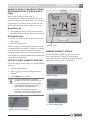
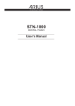
Thermostat
Installation Manual
Series
tTSTBM3H2CPH6W-A thermostat and
Wireless Communicating Base Module
TSTBM3H2CPH6W-A
6 720 220 376 Revised 02-13
of Contents
2Table
TSTBM3H2CPH6W-A
Table of Contents
Thermostat Applications Guide.............................................................................. 3
Power Type............................................................................................................. 3
Thermostat Quick Reference.................................................................................. 3
Installation Tips...................................................................................................... 4
Removing the Private Label Badge......................................................................... 4
Wall locations......................................................................................................... 4
Base Module—Basement Installation...................................................................... 5
Base Module—Attic Installation .............................................................................. 5
Wiring..................................................................................................................... 5
Base Module Subbase Installation......................................................................... 5
Thermostat Installation and wiring......................................................................... 6
Battery Installation................................................................................................. 6
Mount Thermostat and Base Module...................................................................... 7
Wiring Schematicss................................................................................................ 8
Terminal Designations on Base Module................................................................ 12
Terminal Designations on TSTBM3H2CPH6W-A Master Thermostat.................... 12
Powering the TSTBM3H2CPH6W-A Master Thermostat....................................... 12
Establishing Communication between TSTBM3H2CPH6W-A
Master Thermostat and the Base Module............................................................. 13
Using Multiple TSTBM3H2CPH6W-A wireless thermostats.................................. 13
Technician Setup Menu........................................................................................ 14
Understanding Swing And Staging ...................................................................... 22
HUM Terminal....................................................................................................... 22
DHM Terminal....................................................................................................... 22
Humidification / Dehumidification Recommendation for Bosch Heat Pump ....... 23
Setting Target Humidity Setpoint......................................................................... 23
Ambient Humidity Display.................................................................................... 23
Recommended Cooling Settings:......................................................................... 24
Set Time............................................................................................................... 24
Programming........................................................................................................ 24
Specifications ...................................................................................................... 27
Troubleshooting ................................................................................................... 27
Contact your local Bosch Dealer........................................................................... 28
Limited Warranty.................................................................................................. 29
Caution
Warning: If you are setting up this thermostat for an AC unit with electric
heat, or gas furnace, it is imperative that the the “FAN OPERATION”
menu feature is set to ELE or GAS, which ever applies. The default
setting is GAS; if electric heat strips are installed and the default value
of GAS is used, it is possible that the electric heat strips can become
energized without the blower motor on when there is a call for heat.
Reference the Tech Menu Setup section on how to change this feature.
6 720 220 376
Subject to change without prior notice
Revised 02-13
TSTBM3H2CPH6W-A
Thermostat Quick Reference
The TSTBM3H2CPH6W-A offers the
following:
• 3 stages of heating
3
THERMOSTAT QUICK REFERENCE
Getting to know your thermostat
• 2 stages of cooling
2
• Temperature averaging with remote sensors
• Wireless control
5
• 5+1+1 & 7 Day Programmable
1
Thermostat Applications Guide
Description
Gas or Oil Heat
Yes
Electric Furnace
Yes
Heat Pump (No Aux. or Emergency Heat)
Yes
Heat Pump (with Aux. or Emergency Heat)
Yes
Multi-stage Systems
Yes
Heat Only Systems
Yes
Cool Only Systems
Yes
Dual Fuel Systems
Yes
Millivolt
No
Humidity
Yes
Auto Change Over
Yes
7
6
3
1.LCD Display
2. Glow in the Dark Light Button*
3.Fan Button
4. System Button
5. Temperature Setpoint Buttons
Power Type
6. Menu Button
• Battery Power*
• Hardwire (Common Wire)
7. Humidity Button
• Hardwire (Common Wire) with Battery Backup
Caution
* If using remote sensors the thermostat must be hardwired.
A trained, experienced technician must
install this product. Carefully read these
instructions. You could damage this product
or cause a hazardous condition if you fail to
follow these instructions.
Caution
This thermostat is shipped from the factory to
operate a conventional heating and cooling
system. This thermostat will also operate a
heat pump system. See the “heat pump”
confi guration step in the Tech Menu setup of
this manual to configure the thermostat for
heat pump applications.
Revised 02-13
4
Subject to change without prior notice
NOTE ABOUT THE LIGHT BUTTON:
This button is used to light up the display, but
it is also used to set up communication with
the base module. DO NOT hold the light
button down for more then 10 seconds,
unless you are performing the initial
communication setup steps.
The low battery indicator
is displayed
when the AA battery power is low. If the user
fails to replace the battery within 21 days, the
thermostat display will only show the low
battery indicator as a final warning before the
thermostat becomes inoperable. The batteries
are located on the back of the thermostat.
6 720 220 376
4Installation
TSTBM3H2CPH6W-A
Tips
Days of the week and time. Flashes ambient
humidity level. May also flash outside temperature
when used with TSTBM-OTS--TW-A. OUTDOOR will show.
Programmable Time
Period Icons:
This thermostat has
4 programmable
time periods per day.
HOLD is displayed when thermostat
program is permanently overridden.
Displays the user selectable
setpoint temperature.
System operation indicators:
Temperature:
Indicates the current
system temperature.
COOL
HEAT
FAN
The COOL, HEAT or FAN icon will display
when the COOL, HEAT or FAN is on.
Humidity:
Shows the humidity target
setpoint settings and keys.
Clean Display:
Pressing CLEAN DISPLAY
will allow 30 seconds to clean
the display. The keys will be
inoperable during this time.
CLEAN will appear if your
contractor has programmed a
filter change reminder. Press
CLEAN when filter has been
replaced to reset the filter
2
change reminder timer.
REMOTE indicates a remote
has control of the system.
NOTE: The compressor delay feature is
active if these icons are flashing. The
compressor will not turn on until the
5 minute delay has elapsed.
Additional Stages of Heating or Cooling;
+1 represents 1 additional stage of
cooling or heating (2 total); +2 means
2 additional stages of heating (3 total)
Low Battery Indicator:
Replace batteries when
this indicator is shown.
Program Menu Options:
Shows different options
during programming.
Wireless Icon
System Information:
Shows which zone or zones are
controlling your system. Shown only
when one or more indoor sensors
TSTBM-RRS--TW-A are connected.
1
Installation Tips
7
Wall locations
4
Removing the Private Label Badge
The thermostat should be installed approximately 4
to 5 feet above the floor. Select an area with average
temperature and good air circulation.
Do not install thermostats in locations that are:
• On an exterior wall
• In direct sunlight
• Where there may be concealed chimneys or pipes
behind the wall
On the back of the thermostat insert 2 AA Alkaline
• Close to a window or door leading outside
batteries (included).
• Close
to objects
radiating
heat such as fireplaces,
Pull the thermostat directly away
from
the wall
to
Gently slide a scredriver into the bottom edge of the
radiators, or any other appliance
access the batteries. A firm tuglighting,
will be space
required
badge. Gently trun the screwdriver counter
• In areas that do not require conditioning
toshould
remove
theeasily.
thermostat
clockwise. The badge
pry off
Do not from the subbase
mounted on the wall.
• In dead spots or where drafts can occur (behind
use force.
doors or in corners)
All Bosch thermostats use the same
universal magnetic badge. Contact your local
Bosch distributor to learn more about our
free private label program.
Caution
6 720 220 376
• Close to hot or cold air ducts
Pick an installation location that is easy for
the user to access. The temperature of the
location should be representative of the
building.
Subject to change without prior notice
Revised 02-13
n
n
TSTBM3H2CPH6W-A
Base Module—Basement Installation
Installation
Base Module—Basement
Installation
5
Wiring
Wireless Range
Range between the TSTBM3H2CPH6W-A and the
base module is up to 100 feet with no obstructions
and up to 50 feet in standard residential metal,
brick, and concrete construction. To extend the
range try placing the base unit higher if in a
basement or further away from large metal objects.
1. If you are replacing a thermostat, make note of
the terminal connections on the thermostat
that is being replaced. In some cases the wiring
connections will not be color coded. For
example, the green wire may not be connected
to the G terminal.
2. Loosen the terminal block screws. Insert wires
then retighten terminal block screws.
Do not install the base module in locations:
Caution
• Where temperatures could exceed 150°F
• That could be exposed to rain or snow
• That could be exposed to freezing conditions
• That are behind a chimney
• Where high moisture is possible
The base module is NOT water or
weatherproof and should only be installed in a
conditioned space.
All components of the control system and the
thermostat installation must conform to
Class II circuits per the NEC Code.
Wire specifications
Use shielded or non-shielded 18 - 22 gauge
thermostat wire.
Base Module Subbase
Installation AND WIRING
Vertical mount
Base Module—Attic Installation
Attic installation of the base module should be
avoided. Instead, locate a closet near the air
conditioning unit, then mount the base module high
on the wall inside the closet or on the ceiling of the
closet. This location will insure the base module is
below the 150ºF maximum ambient temperature
specification.
For vertical mount put one screw top and one screw
bottom. For horizontal mount put one screw left
and one screw right.
UP
Mercury Notice: All Bosch thermostats are
mercury free. However, if the product you are
replacing contains mercury, dispose of it
Caution
properly. Your local waste management
authority can give you instructions on recycling
and proper disposal.
B
G
W1/E
Y1
W2
Y2
H
D
Horizontal mount
Horizontal mount
Vertical mount
For vertical mount put one screw top and one
screw bottom. For horizontal mount put one screw
left and one screw right.
Caution
Revised 02-13
Rc
O
Failure to disconnect the power before
beginning to install this product can cause
electrical shock or equipment damage.
Rh
C
Subject to change without prior notice
Wire the base module’s subbase the same
way you would wire a hardwired thermostat
subbase.
To establish communication from the base
module to master thermostat, refer to the
directions in the TSTBM3H2CPH6W-A
Thermostat-Base Module Communication
setup procedure below in this manual.
6 720 220 376
6Thermostat
TSTBM3H2CPH6W-A
Installation and Wiring
The base module must be hardwired
(C and R terminals connected to 24V power).
n
Thermostat Installation and
wiring
Caution
UP
Caution
C
Battery installation is optional if there are no
remotes connected to the Master Thermostat (C
terminal connected). If you connect an outdoor
remote and/or indoor remote sensors it is required
the thermostat be hardwired.
To ensure a solid fit between the thermostat
and the subbase, mount the subbase on a
flat wall with the drywall anchors flush to the
wall. Using the screws and drywall anchors
that were provided with the thermostat.
Vertical mount
Horizontal
mount
R
Battery Installation
The TSTBM3H2CPH6W-A can be battery
powered only if used as a stand-alone
thermostat solution. The TSTBM3H2CPH6W-A
must be hardwired (C and R terminals
connected to 24V power) if remote sensors
(TSTBM-RRS--TW-A or TSTBM-OTS--TW-A)
are used.
Horizontal
mount
Vertical mount
C
R
On the back of the thermostat insert 2 AA
Alkaline batteries (included).
6 720 220 376
Subject to change without prior notice
Revised 02-13
on
Mount Thermostat And Base Module
TSTBM3H2CPH6W-A
Mount Thermostat and Base
Module
Align the 4 tabs on the subbase with corresponding
slots on the back of the thermostat or base module.
Then push gently until the thermostat or base module.
To insure a solid fit between the
thermostat and the subbase:
1. Mount subbase to a flat wall
2. Use screws provided
3. Drywall anchors should be flush with the wall
4. Wires should be pushed into the wall
Revised 02-13
Subject to change without prior notice
6 720 220 376
7
8
TSTBM3H2CPH6W-A
Wiring Schematics
TYPICAL WIRING SCHEMATICS
WIRELESS WITH BASE MODULE TSTBM3H2CPH6W-A
3H/2C HEAT PUMP
TSTBM3H2CPH6W-A
THERMOSTAT
C
R
PACKAGED
HEAT PUMP
BASE MODULE
RH
R
RC
G
G
Y1
Y1
Y2
Y2
C
D
O
B
C
W1
O
W2/E
B
W1/E
W2
H
2H/1C HEAT PUMP
TSTBM3H2CPH6W-A
THERMOSTAT
C
R
BASE MODULE
PACKAGED
HEAT PUMP
RH
R
RC
G
G
Y1
Y1
Y2
Y2
C
D
O
B
C
W1
O
W2/E
B
W1/E
W2
H
6 720 220 376
Subject to change without prior notice
Revised 02-13
Wiring Schematics
TSTBM3H2CPH6W-A
3H/2C SPLIT HEAT PUMP
FAN COIL / AIR
HANDLER
COMPRESSOR
SECTION
BASE MODULE
R
RH
R
G
RC
Y1
Y1
G
Y2
Y2
Y1
C
C
Y2
O
W1
D
B
W2/E
C
O
TSTBM3H2CPH6W-A
THERMOSTAT
B
C
W1/E
R
W2
H
3H/2C HEAT PUMP WITH GAS/OIL
FURNACE HEAT BACKUP
FAN COIL /
FURNACE
BASE MODULE
R
RH
R
G
RC
Y1
Y/Y1
G
Y2
COMPRESSOR
SECTION
Y2
Y1
C
C
Y2
O
W/W1
D
B
C
C TSTBM3H2CPH6W-A
THERMOSTAT
R
O
B
W1/E
W2
H
Revised 02-13
Subject to change without prior notice
6 720 220 376
9
10 TSTBM3H2CPH6W-A
Wiring Schematics
JUMP "E" & "W2" AT THE TSTBM3H2CPH6W-A
THERMOSTAT WHEN THE HEAT PUMP EQUIPMENT
DOES NOT HAVE AN EMERGENCY HEAT TERMINAL
TSTBM3H2CPH6W-A
THERMOSTAT
C
PACKAGED
HEAT PUMP
BASE MODULE
R
RH
R
RC
G
G
Y1
Y1
Y2
Y2
C
D
O
C
W
B
O
B
W1/E
W2
H
2H/2C AIR CONDITIONING W/
ELECTRIC HEAT BACKUP
FAN COIL / AIR
HANDLER
BASE MODULE
COMPRESSOR
SECTION
R
RH
R
G
RC
Y1
Y1
G
Y2
Y2
Y1
C
C
Y2
W1
D
W2
C
O
B
TSTBM3H2CPH6W-A
THERMOSTAT
C
W/E
R
W2
H
6 720 220 376
Subject to change without prior notice
Revised 02-13
Wiring Schematics
TSTBM3H2CPH6W-A
UNIT WITH ACTIVE OR PASSIVE
DEHUMIDIFICATION AND HUMIDIFICATION RELAY
COMMON FROM
HVAC EQUIPMENT
HVAC
EQUIPMENT
PASSIVE / ACTIVE
DEHUMIDIFICATION
BASE MODULE
RH
RC
G
Y1
Y2
D
C
HUMIDIFIER
EQUIPMENT
HUMIDIFIER
SOLENOID
O
B
W/E
W2
H
Revised 02-13
Subject to change without prior notice
6 720 220 376
11
12 TSTBM3H2CPH6W-A
Terminal Designations
Terminal Designations on Base Module
Terminal
2 Heat 2 Cool
Conventional System
2 Heat 2 Cool
Heat Pump System
3 Heat 2 Cool
Heat Pump System
RC
Transformer power (cooling)
Transformer power (cooling)
Transformer power (cooling)
RH
Transformer power (heating)
Transformer power (heating)
Transformer power (heating)
C
Transformer common
Transformer common
Transformer common
B
Energized in heating
(not used)
Heat pump changeover valve
energized in heating
Heat pump changeover valve
energized in heating
O
Energized in cooling
(not used)
Heat pump changeover valve
energized in cooling
Heat pump changeover valve
energized in cooling
G
Fan relay
Fan relay
Fan relay
W/E
First stage of heat
Emergency heat relay
Emergency heat relay
Y
First stage of cool
First stage of heat & cool
First stage of heat & cool
Y2
Second stage of cool
Second stage of cool
Second stage of cool and second
stage of heat
W2
Second stage of heat
Auxiliary heat relay,
second stage of heat
Auxiliary heat relay,
third stage of heat
H
Humidify
Humidify
Humidify
D
Dehumidify
Dehumidify
Dehumidify
TSTBM3H2CPH6W-A Wiring Notes:
If separate transformers for heating and cooling
are not present, jump RC and RH
terminals at
Caution
the thermostat and connect the HOT lead from
the transformer to RC
- In systems with no emergency heat relay, a
jumper can be installed between E and W2
- Due to the internal circuitry, a voltage
potential will exist across any terminal and
common if that terminal is not connected to a
resistive load.
- Bosch Water Source Heat Pumps utilize “O”
type reversing valve operation. If your heat
pump utilizes “B” type reversing valve
operation, substitute the wiring for the “O”
terminals for “B”.
Terminal Designations on TSTBM3H2CPH6W-A Master Thermostat
Terminal
2 Heat 2 Cool
Conventional System
2 Heat 2 Cool
Heat Pump System
3 Heat 2 Cool
Heat Pump System
R
24 VAC Transformer power
24 VAC Transformer power
24 VAC Transformer power
C
Transformer common
Transformer common
Transformer common
Powering the TSTBM3H2CPH6W-A
Master Thermostat
If remote sensors (TSTBM-OTS--TW-A or
TSTBM-RRS--TW-A) are to be used with the wireless
system you must hardwire the TSTBM3H2CPH6W-A
master thermostat.
6 720 220 376
Once the base module and the thermostat have been
securely mounted and both have been completely
wired for the applicable system, communication can
be established between the two.
Subject to change without prior notice
Revised 02-13
Establishing Communication Links
Establishing Communication
between TSTBM3H2CPH6W-A
Master Thermostat and the Base
Module
TSTBM3H2CPH6W-A
13
Step 1.
LED Relay
Indicator
Easy, Two Step Communication Link
To set up the initial link between the Master
Thermostat and the base module please follow
these steps:
1. Press and hold the base module button for 3
seconds. The Blue LED will flash when ready to
receive initial signal from TSTBM3H2CPH6W-A.
(Base module must be powered by 24V. Blue
LED will be continuously on when 24V power is
present.)
2. Hold the Light key of the TSTBM3H2CPH6W-A
for 10 seconds, the Blue LED on the base
module will stop flashing after communication
has been established between base module and
the TSTBM3H2CPH6W-A.
Caution
Insert batteries in the TESTBM3H23PH6W-A
thermostat and have it in hand while at the base
module when performing the initial
communication setup. Having the two devices
together to confirm that communication has
been established will be much easier. Now
place the thermostat on the wall mounting plate
in its intended permanent location.
The Blue LED on the base module will be on
when power is present. The Blue LED will flash
3 times every time it receives a signal from
TSTBM3H2CPH6W-A. When a relay is on the
corresponding LED relay indicator will be on.
Re-linking the thermostat and Base Module is
not necessary for power outages or after a
thermostat battery change.
The base module contains multiple LED lights
indicating the status of the HVAC equipment
Using Multiple TSTBM3H2CPH6W-A
wireless thermostats
Although utilizing multiple TSTBM3H2CPH6W-A
wireless thermostats in one location are all centered
around 916 MHz, a random unique communication
code is established between a specific thermostatbase module combination. This random code will
enable multiple (100+) TSTBM3H2CPH6W-A
wireless thermostats to function in one installation
site without interfering with one another.
If the base module does not receive a signal
from the TSTBM3H2CPH6W-A Caution
for 15 minutes
it will turn off all relays until communication is
reestablished. The Blue LED on the base
module will also turn off to show
communication has been lost.
If communication has been lost for 1 hour and
if the freeze protection feature is enabled, heat
and emergency heat relays will be turned on.
The heat and emergency heat relays will turn
on for 10 minutes every hour if there has been
a call for heat in the last 24 hours.
Revised 02-13
Subject to change without prior notice
The base module is not water proof.
Do not install the base module in the following
locations:
Behind a Chimney
Where Temp exceeds 150F
Where rain, snow or extreme hot/cold is
possible.
6 720 220 376
14 TSTBM3H2CPH6W-A
Technician Setup Menu
Step 2.
Technician Setup Menu
Light key
This thermostat has a technician setup menu for easy
installer configuration. To set up the thermostat for
your particular application:
1. Press MENU button
2. Press and hold TECHNICIAN SETUP button for 3
seconds. This 3 second delay is designed so that
homeowners do not accidentally access the
installer settings.
3. Configure the installer options as desired using
the table below. Use the [-] or [+] keys to change
settings and the NEXT STEP or PREV STEP key to
move from one option to another.
DO NOT hold the light button on the
TSTBM3H2CPH6W-A for more than 10
seconds after Step 2 above has been
completed.
Caution
Holding the light button down will break the
communication link and the base module
button will need to be pressed again to
reestablish communication.
6 720 220 376
Only press DONE key when you want to exit
the Technician Setup options.
Subject to change without prior notice
Revised 02-13
Technician Setup Menu
TSTBM3H2CPH6W-A
15
Tech Setup Steps
LCD will show
Filter
Change
Reminder
This feature will flash FILT in
the display after the elapsed
run time to remind the user
to change the filter. A setting
of OFF will disable this
feature.
Adjustment Options
Factory
Default
Settings
You can adjust the filter change
reminder from OFF to 2000 hours of
runtime in 50 hour increments.
OFF
This feature allows the
Room
Temperature installer to change the
calibration of the room
Calibration
You can adjust the room temperature
display to ready -4°F to +4°F above or
below the factory calibrated reading.
0 ºF
Minimum
Compressor
On Time
This feature allows the
installer to select the
minimum run time for the
compressor. For example,
a setting of 4 will force
the compressor to run for
at least 4 minutes every
time the compressor turns
on, regardless of the room
temperature.
You can select the minimum
compressor run time from “off”, “3”,
“4”, or “5” minutes. If 3, 4, or 5 is
selected, the compressor will run
for at least the selected time before
turning off.
OFF
Compressor
Short Cycle
Delay
The compressor short
cycle delay protects the
compressor from “short
cycling”. This feature will not
allow the compressor to be
turned on for 5 minutes after
it was last turned off.
Selecting ON will not allow the
compressor to be turned on for
5 minutes after the last time the
compressor was on. Select OFF to
remove this delay.
ON
Cooling
Swing
The swing setting,
often called “cycle
rate”, “differential” or
“anticipation” is adjustable.
A smaller swing setting will
cause more frequent cycles
and a larger swing setting will
cause fewer cycles.
The cooling swing setting is adjustable 0.5 ºF
from ±0.2°F to ±2°F. For Example: A
swing setting of 0.5°F will turn the
cooling on at approximately 0.5°F
above the setpoint and turn the
cooling off at approximately 0.5°F
below the setpoint.
The swing setting,
often called “cycle
rate”, “differential” or
“anticipation” is adjustable.
A smaller swing setting will
cause more frequent cycles
and a larger swing setting will
cause fewer cycles.
The heating swing setting is
adjustable from ±0.2°F to ±2°F. For
Example: A swing setting of 0.5°F will
turn the heating on at approximately
0.5°F below the setpoint and turn the
heating off at approximately 0.5°F
above the setpoint.
temperature display. For
example, if the thermostat
reads 70° and you would like
it to read 72° then select +2.
(min)
(min)
Heating
Swing
Revised 02-13
Subject to change without prior notice
See Temperature swing example after
the Tech Setup Section
See Temperature swing example after
the Tech Setup Section
6 720 220 376
0.4 ºF
Technician Setup Menu
16 TSTBM3H2CPH6W-A
To lock the keypad, hold down the
or
keys for 3
seconds. You will see a lock in the display. To unlock the
keypad hold down the
or
keys for 3 seconds.
Tech Setup Step (Continued from the previous page)
LCD will show
Factory
Default
Settings
Adjustment Options
Keypad
Lockout
Keypad lockout allows you to
configure the thermostat so that
none or some of the keys do not
function..
PA
Pick PA or FU
PA = partial keypad lockout, which
locks all the keys except the – or
+ keys.
FU = Full keypad lockout, which
locks out all the keys. Note:
Keypad lockout instructions are
below
Heating
Temperature
Setpoint
Limit
This feature allows you to set a
maximum heat setpoint value.
The setpoint temperature cannot
be raised above this value.
Use the – or + keys to select the
maximum heat setpoint.
90 ºF
Cooling
Temperature
Setpoint
Limit
This feature allows you to set a
minimum cool setpoint value.
The setpoint temperature cannot
be lowered below this value.
Use the – or + keys to select the
minmum cool setpoint.
44 ºF
ºF or ºC
Select F for Fahrenheit
temperature read out or select C
for Celsius read out.
ºF for Fahrenheit
ºC for Celsius.
ºF
12 or 24
Hour Clock
You can select either a 12 or 24
hour clock setting.
Use the – or + keys to select 12
or 24 hour clock.
12 Hour
Clock
Morning
Recovery
This feature turns your system on
before the WAKE programming
time to ensure the enviroment
is at the WAKE setpoint when
the WAKE time period begins.
This recovery changes over time
based on the previous day’s
experience.
Use the – or + keys to turn on
or off.
ON
Time
Periods
You can configure this thermostat
to have 2 or 4 programmable
time periods per day.
2 time periods are: Occupied/
Unoccupied
4 time periods are: Wake, Leave,
Return, Sleep
Use the – or + keys to select 2 or
4 time periods per day.
4
6 720 220 376
Subject to change without prior notice
Revised 02-13
Technician Setup Menu
TSTBM3H2CPH6W-A
17
Tech Setup Step (Continued from the previous page)
LCD will show
Program
Options
Adjustment Options
Factory
Default
Settings
Use the – or + keys to select 7d
for 7 day, 5d for 5+1+1, or 0d for
nonprogammable.
5d
Display Light The display light can be
OFF configures display light to come
on only with the light key, which will
save battery power. ON configures the
display light to come on when any key
is pressed.
ON
Contractor
Call Number
Allows you to put your phone
number in the display. You
can choose ON or OFF
If selected ON, you will see the input
screen after pressing next step. Use
the – or + keys to select the desired
number and the FAN or SYSTEM
key to move from one character to
another. See note below on operation.
OFF
Beep
When any key is pressed an
audible beep will sound. You
can choose ON or OFF
If ON is selected the beep will sound.
If OFF is selected, there is no sound.
ON
Heat Pump
When turned on the
thermostat will operate a
heat pump.
1. EM.Heat will show as an
option in the system switch.
2. Y will be first stage of
heat & cool, W/E will be
emergency heat relay & W2
will be auxiliary heat relay.
OFF configures the thermostat for non OFF
heat pump systems.
ON configures the thermostat for heat
pump systems.
System
Switch
You can configure the system
switch for the particular
application:
Heat - Off - Cool,
Heat - Off,
Cool - Off,
Heat - Off - Cool-Auto
Note: EM. Heat will
show if in heat pump
mode.
Use the – or + keys until the desired
application is flashing.
Heat
- Off Cool
Fan
Operation
Select GAS for systems that
control the fan during a call
for heat. Select ELEC to have
the thermostat control the
fan during a call for heat.
GAS or ELEC
If a system with electric heat is being
used, this setting MUST be set to
ELEC. When a call for heat is made,
the fan will not come on if set to GAS.
GAS
You can configure this
thermostat to have a 7 day
program, a 5+1+1 program or
nonprogrammable.
configured to come on when
any key is pressed or only
when the light key is pressed.
(only in HP
mode)
(not available
in HP mode)
Revised 02-13
Subject to change without prior notice
6 720 220 376
18 TSTBM3H2CPH6W-A
Technician Setup Menu
Tech Setup Step (Continued from the previous page)
LCD will show
Gas
Auxiliary for
Heat Pump
(only
available in
HP mode)
This option will turn the heat
pump off 45 seconds after the
auxiliary heat relay turns on.
For 2 heat applications, the
first stage will turn off 45
seconds after the auxiliary
stage turns on.
For 3 heat applications, the
first and second stage will
turn off 45 seconds after the
auxiliary stage turns on.
Adjustment Options
Factory
Default
Settings
Selectable on or off.
OFF
This option should be ON for
applications that uses a gas furnace
for auxiliary heat.
This is an extremely important feature
to set if utilizing a gas furnace.
Operation of the gas furnace while the
compressor is running will overheat
and damage the compressor.
This feature is disabled when a
TSTBM-OTS-TW-A is connected. See
Balance Point feature setup.
Cooling Fan
Delay
(seconds)
You can select the Cooling Fan Delay
from OFF, 15, 30, 60 or 90 seconds.
If 15, 30, 60 or 90 is selected the fan
will not turn on for that many seconds
when there is a call for cool and
will run for that many seconds after
satisfying a call for cool.
The cooling fan delay setting
will delay the fan from
coming on in cool mode
and keep running after the
compressor shuts off for a
short time to save energy in
some systems.
OFF
This feature is disabled when a
TSTBM-OTS--TW-A is used. See
Balance Point feature setup.
Outdoor
Sensor
Enables the use of an outdoor
sensor TSTBM-OTS--TW-A.
Connecting a TSTBM-OTS-TW-A allows for a balance
point setting.
Selecting YES requires
the TSTBM3H2CPH6W-A
master thermostat to be
powered with 24V on C and R
terminals.
See TSTBM-OTS--TW-A user
guide for more information.
When NO is selected the thermostat
is unable to connect to an outdoor
remote sensor TSTBM-OTS--TW-A.
NO
When YES is selected the thermostat
is able to connect to an outdoor
remote sensor TSTBM-OTS--TW-A.
Press and hold connect button
on TSTBM-OTS--TW-A until the
TSTBM3H2CPH6W-A says FOUND
OUTDOOR on display.
Connect an optional TSTBM-OTS--TW-A
outdoor remote temperature sensor
to
Caution
enable the balance point tech setup option.
Up to four TSTBM-RRS--TW-A indoor temperature
sensors can be connected to one
TSTBM3H2CPH6W-A thermostat.
This allows for 5 sensing points (zones). For Example:
The local ( TSTBM3H2CPH6W-A) plus four TSTBMRRS--TW-A sensors enables 5 sensing points.
See the tech setup menu below to activate this feature.
Reference the installation manual for the TSTBM-RRS-TW-A remote room sensor for detailed instructions on
connection and setup.
6 720 220 376
Subject to change without prior notice
Revised 02-13
Technician Setup Menu
TSTBM3H2CPH6W-A
19
Tech Setup Step (Continued from the previous page)
LCD will show
Adjustment Options
Factory
Default
Settings
Remote
Sensor
Enables the use of up to four
indoor sensors TSTBM-RRS-TW-A. Selecting YES requires
the TSTBM3H2CPH6W-A master
thermostat to be powered with
24V on C and R terminals.
NO
When NO is selected the
thermostat is unable to connect to
an indoor remote sensor TSTBMRRS--TW-A. When YES is selected
the thermostat is able to connect
to up to four indoor remote
sensors TSTBM-RRS--TW-A. Go to
the next step FINDING SENSOR
to connect TSTBM-RRS--TW-A.
Finding
Sensor
This step connect TSTBM-RRS-TW-A to TSTBM3H2CPH6W-A.
The previous step Remote Sensor
must be set to YES in order to
connect an TSTBM-RRS--TW-A.
The number shown represents
the zone Use – or + to select the
zone you wish to connect.
The zone setting on the
TSTBM3H2CPH6W-A and the
TSTBM-RRS--TW-A must be the
same to connect.
See TSTBM-RRS--TW-A user guide
for detailed TSTBM-RRS--TW-A
connection information.
See note above on previous page
for more information.
1
Local Temp
Sensor
Disable the sensor on the master.
At least one TSTBM-RRS--TW-A
indoor remote sensor must be
connected to disable the local
TSTBM3H2CPH6W-A sensor.
YES enables local
TSTBM3H2CPH6W-A sensor
NO disables local
TSTBM3H2CPH6W-A sensor
YES
Freeze
Protection
Turns on the heat for 10
minutes each hour if unable
to communicate with the
TSTBM3H2CPH6W-A master
thermostat if there has been a
call for heat in the last 24 hours.
YES enables freeze protection
NO disables freeze protection
NO
Stages of
Heat
You can configure the thermostat
to operate a 3 stage heat pump
system.
2H 2C = 2 heat, 2 cool
3H 2C = 3 heat, 2 cool
This feature only shows if
Technician Setup Step for HEAT
PUMP is set to ON.
Use the – or + key to change
between 2 heat and 3 heat.
2 heat will use Y1 as first stage
and W2 as auxiliary.
3 heat will use Y1 as first stage,
Y2 as second stage and W2 as
third stage.
2H/2C
Balance
Point
Balance point can eliminate the
need for a fossil fuel kit.
An outdoor temperature above
balance point will cause the
thermostat to only allow the
Y terminal(s) to energize. An
outdoor temperature below
balance point will cause the
thermostat to only allow the W2
to energize.
YES
10, 20, 30, 35, 40, 45, 50 outdoor
temperature balance point
setting.
NO
NO
(only
available in
HP mode)
(Requires
TSTBM-OTSTW-A and in
HP mode)
Revised 02-13
Subject to change without prior notice
6 720 220 376
20 TSTBM3H2CPH6W-A
Technician Setup Menu
Balance Point:
The system operates differently when a balance
point is used on a dual fuel system. The balance
point outdoor temperature setting will be the
outdoor temperature at which the thermostat
chooses either the heat pump or gas furnace. For Example:
A balance point setting of 30ºF will turn on only the heat
pump above 30ºF and only the gas furnace below 30ºF. Y1
will be stage one above 30ºF and W2 will be stage one
below 30ºF.
Tech Setup Step (Continued from the previous page)
LCD will show
Factory
Default
Settings
Adjustment Options
Balance
Point
Balance point with electric
auxiliary can optimize heat pump
usage. An outdoor temperature
above balance point will cause
the thermostat to only allow
the Y terminal(s) to energize.
An outdoor temperature below
balance point will cause the
thermostat to allow the Y
terminal(s) and the W2 terminal to
energize.
Note: Only shows up if Heat Pump
is set to YES and Outdoor Sensor
is turned ON and Gas Auxiliary is
turned OFF
10, 20, 30, 35, 40, 45, 50 outdoor
temperature balance point setting
NO
Balance
Run Time
Balance point run time will
allow the W2 auxiliary terminal
to energize even if outdoor
temperature is above the selected
balance point temperature. If
enabled, auxiliary will energize for
the current cycle after the balance
point run time has expired.
YES 15, 30, 45, 60, 75, 90
continuous run time minutes.
NO
NO
Humidify
This feature adds humidity when
System key is in Heat.
Use the – or + keys to turn off or
on.
If ON is selected the humidity will
be displayed on the main screen
and Hum terminal will energize
when humidity setpoint is above
ambient humidity in Heat mode.
off
Dehumidify This feature removes humidity
Use the – or + keys to turn on or
off.
If ON is selected the humidity will
be displayed on the main screen
and DHM terminal will energize
when humidity setpoint is below
ambient humidity in Cool mode.
off
Humidity
Calibration
Use the – or + keys to adjust the
calibration +/– 3.
0
(Gas
Auxiliary
OFF)
(Requires
enabling
Balance
Point
Feature)
when System key is in Cool.
This feature allows the installer
to change the callibration of the
ambient humidity displayed.
6 720 220 376
Subject to change without prior notice
Revised 02-13
Technician Setup Menu
TSTBM3H2CPH6W-A
21
Tech Setup Step (Continued from the previous page)
LCD will show
Adjustment Options
Factory
Default
Settings
Dehumidify This feature forces the A/C to run
longer to remove humidity when
with AC
Use the – or + keys select YES or
NO.
If selected YES allows over
cooling to be used to control
humidity in Cool mode.
If NO is selected the system will
not use over cooling.
NO
Over Cool
Limit
°F, °C
The amount of over cooling
allowed when using A/C to
remove humidity. This screen is
only shown when ON is selected
in the “Dehumidify with AC” tech
setup step.
Use the – or + keys to select the
maximum number of degrees of
over cool.
Options are: 2, 3, 4, 5
3
HUM
Terminal
Options for how the Hum terminal
energizes.
Use the – or + key to select one
of the four options.
View the HUM Terminal chart
below for an explanation of these
options.
1
DHM
Terminal
Option for how DHM terminal
energizes.
Use the – or + keys to select one
of the four options.
View the DHM Terminal chart
below for an explanation of these
options.
1
Staging
Delay
This feature allows a delay to
occur when a second and third
stage is needed This allows the
previous stage extra time to
satisfy setpoint.
Use the – or + keys to select the
number of minutes to delay each
stage.
OFF
This feature allows the thermostat
to keep multiple stages of heat
or cool energized until setpoint is
satisfied
Use the – or + keys to select the
number of minutes to turn on or
off.
needed. The A/C will “over cool”
the room a few degrees until the
humidity reaches the desired
setpoint.
Satisfy
Setpoint
Revised 02-13
Subject to change without prior notice
OFF 5, 10, 15, 30,45, 60,90 delay
minutes.
6 720 220 376
22 TSTBM3H2CPH6W-A
HUM and DHM Terminals
UNDERSTANDING SWING AND STAGING
Temp
Actions
All Bosch thermostats have adjustable swings.
Cycling your HVAC system is a balance between user
comfort and equipment efficiency. Equipment wear
and tear is also a consideration.
71°F
1st Stage Off
70°F
Set point
69°F
1st Stage On / 2nd Stage Off
68°F
2nd Stage On / 3rd Stage Off
• User comfort is maximized by small swings
67°F
3rd Stage On
• Equipment efficiency is maximized by large swings
• Equipment wear and tear is minimized by large
swings
• The ideal swing is one at which the system runs as
long and with as few cycles as possible without the
homeowner being uncomfortable
The 1st stage will energize at 69°F and turn off at
71°F. The 2nd stage will energize at 68°F and turn
off at 69°F. The 3rd stage will energize at 67°F and
turn off at 68°F.
HUM Terminal
• Modern systems are designed to run longer with
fewer cycles for best efficiency
• Staging systems are designed to be most efficient
on first stage (excluding dual fuel systems)
• Equipment life is reduced by frequent on/off cycles
• The 1st stage energizes at 1x swing, the 2nd stage
at 2x swing and the 3rd stage at 3x swing.
Example:
HUM TERMINAL SETTING
1
"H" terminal is energized when a heating
call is made or a FAN ON call is made
2
"H" terminal is energized when a heating
call is made
3
"H" and "G" terminals are energized
with and without a heating call
4
"H" terminal only is energized without
heating call and remains energized with
a heating call
* These setting and condition explanations assume
humidity set point has not been satisfied and the
equipment is attempting to actively humidify
• Thermostat system switch set to heat
• Swing setting is 1°F
• Set point is 70°
DHM Terminal
DHM TERMINAL SETTING
Without Cool-to-Dehumidify Feature Active
With Cool-to-Dehumidify Feature Active
1
First stage of cooling (Y1,O,G) along with “D”
terminal are energized even if space temp is
satisfied (within the over cool limit)
“D” terminal is energized when a cooling call is
made or a FAN ON call is made.
When the set point is beyond the over cool limit,
the “D” will also energize with a FAN ON call
“D” and "G" terminals energized even when
space temp is satisfied.
“D” and “G” remain energized if cooling call is
made.
“D” and “G” terminals only are energized even
when space temp is satisfied.
“D” and “G” remain energized if cooling call is
made.”
3
“D” terminal only is energized with and without
a cooling call.
“D” terminal only is energized with and without a
cooling call
4
“D” terminal only is energized without a cooling
call.
“D” terminal is de-energized when a cooling call
is made.
“D” terminal is energized without a cooling call
“D” terminal is de-energized when a cooling call is
made”
2
* These setting and condition explanations assume humidity set point has not been satisfied and the equipment is attempting to
actively dehumidify
6 720 220 376
Subject to change without prior notice
Revised 02-13
TSTBM3H2CPH6W-A
Setting Target Humidity Setpoint
23
Humidification / Dehumidification
Recommendation for Bosch Heat
Pump
With a residential Bosch Heat Pump, it is
recommended to use the cool-to-dehumidify option
with the equipment. When a humidity call is made by
energizing the “D” terminal, the fan motor will slow
down to better dehumidify the air by over cooling.
Humidification
1. Select HUM Terminal #1. This will work with Bosch
Humidifier Series and replace the manual humidistat.
Dehumidification
1. Enable Cool-to-dehumidify feature from the Tech
Menu Setup
2. Select DHM Terminal #1
HUMIDITY KEY
These are just typical settings that would be used with
a residential Bosch heat pump. Ultimately, the installer
must be aware of the system that the thermostat is
Ambient Humidity Display
controlling and the sequence in which dehumidification
Ambient humidity will flash opposite the day and
and humidification are being addressed to establish the
time, if the optional TSTBM-OTS--TW-A outdoor
correct thermostat settings.
temperature sensor is installed the ambient outdoor
temperature will also cycle in the display.
Setting Target Humidity Setpoint
Follow the steps below to change your target humidity
setpoint.
1. Press the HUMIDITY key
2. Use the
setpoint.
key to select the target humidity
3.Press DONE when completed
AMBIENT HUMIDITY
“D” and “H” Terminals use the “R” Terminal to
complete the circuit. This is a normally open circuit.
The target humidity setpoint is not programmable.
Unlike temperature, humidity does not change
quickly and should not be programmed.
Humidity is only energized during heat.
Dehumidify is only energized during cool. Heat
and Cool each have their own target setpoints.
DAY & TIME
OUTDOOR TEMPERATURE
TARGET HUMIDITY SETPOINT KEYS
Revised 02-13
Subject to change without prior notice
6 720 220 376
24 TSTBM3H2CPH6W-A
Setting 5+1+1 Program
Recommended Heating Settings:
Set 5+1+1 Program Schedule
Increasing Humidity
To customize your 5+1+1 program schedule, follow
these steps:
The table below shows recommended indoor
humidity levels in relation to outdoor temperatures
during heating (adding humidity).
Weekday:
1.Select HEAT or COOL using the SYSTEM key.
Outside Temperature
(0°F)
Recommended
Relative Humidity
Caution
+20º and above
35% to 40%
+10º
30%
2.Press MENU
0º
25%
-10º
20%
3.Press SET SCHED.
-20º
15%
You have to program heat and cool each
separately.
Monday-Friday is displayed and the WAKE
icon is shown. You are now programming the
WAKE time period for the weekday setting.
Caution
Recommended Cooling Settings:
Consult your professional HVAC technician for
recommended settings for your climate.
Additional step if TSTBM-RRS--TW-A
indoor remote sensor is connected.
Set Time
1.Press MENU
2.Press SET TIME
3. Day of the week will be flashing. Use the [+] or
[–] key to select the current day of the week.
4Press NEXT STEP
5. The current hour is flashing. Use the [+] or [–] key to
select the current hour. When using 12-hour time,
make sure the correct a.m. or p.m. choice is selected.
6.Press NEXT STEP
7. Minutes are now flashing. Use the [+] or [–] key
to select current minutes.
8.Press DONE when completed
Programming
All programmable Bosch thermostats are shipped with
an energy saving pre-program. You can customize this
default program by following the Set Program Schedule
Instructions below.
Your thermostat can be programmed to have each day
Caution
of the week programmed uniquely (7days), all the
weekdays the same with a separate program for
Saturday and a separate program for Sunday (5+1+1),
or nonprogrammable. There are four time periods for
each day (WAKE, LEAVE, RETURN, SLEEP).
This thermostat has a programmable fan feature,
which allows you to run the fan continuously during
any time period.
6 720 220 376
The TSTBM3H2CPH6W-A master thermostat will
either average all sensors (system average) or
only use one sensor for the system ambient
temperature (priority). The default setting is
SYSTEM AVERAGE, which means all sensors are
averaged to create the system average ambient
temperature reading. The NEXT ZONE key can
be pressed to change the priority. The system
information area of the display shows the
priority.
For Example: There is an TSTBM-RRS--TW-A
connected and it is named REMOTE 1. If the
NEXT ZONE key is pressed until REMOTE 1 is
shown, then the REMOTE 1 ambient
temperature reading will be used exclusively for
that time period. All other sensors will be
ignored.
4. Time is flashing. Use the [+] or [–] key to make
your time selection for the weekday WAKE time
period.
If you want the fan to run continuously during
this time period, select ON with the FAN (3) key.
5.Press NEXT STEP
6. The setpoint temperature is flashing. Use the [+]
or [–] key to make your setpoint selection for the
weekday wake time period.
7.Press NEXT STEP
Subject to change without prior notice
Revised 02-13
HUM and DHM Terminals
TSTBM3H2CPH6W-A
25
Factory Default Program
Day of the
Week
Weekday
Saturday
Sunday
Events
Time
Setpoint
Events Time
Temperature (Heat)
Setpoint
Temperature (Cool)
Zone (TSTBM-RRS--TW-A
Temperature Sensor is
connected)
Wake
6 a.m.
70° F (21° C)
75° F (24° C)
System Average
Leave
8 a.m.
62° F (17° C)
83° F (28° C)
System Average
Return
6 p.m.
70° F (21° C)
75° F (24° C)
System Average
Sleep
10 p.m.
62° F (17° C)
78° F (26° C)
System Average
Wake
8 a.m.
70° F (21° C)
75° F (24° C)
System Average
Leave
10 a.m.
62° F (17° C)
83° F (28° C)
System Average
Return
6 p.m.
70° F (21° C)
75° F (24° C)
System Average
Sleep
11 p.m.
62° F (17° C)
78° F (26° C)
System Average
Wake
8 a.m.
70° F (21° C)
75° F (24° C)
System Average
Leave
10 a.m.
62° F (17° C)
83° F (28° C)
System Average
Return
6 p.m.
70° F (21° C)
75° F (24° C)
System Average
Sleep
11 p.m.
62° F (17° C)
78° F (26° C)
System Average
You can use the table below to plan your customized program
schedule if using 5+1+1.
Custom User Schedule
Day of the
Week
Events
Time
Setpoint
Events Time
Temperature (Heat)
Setpoint
Temperature (Cool)
Zone (TSTBM-RRS--TW-A
Temperature Sensor is
connected)
Wake
Weekday
Leave
Return
Sleep
Wake
Saturday
Leave
Return
Sleep
Wake
Sunday
Leave
Return
Sleep
Revised 02-13
Subject to change without prior notice
6 720 220 376
26 TSTBM3H2CPH6W-A
Setting 5+1+1 Program
8. There are a total of 4 programmable times. After
you have set the “Wake” time above, set the
remaining three; “Leave”, “Return”, and “Sleep”
Repeat steps 4 through 7 for weekday LEAVE
time period, for weekday RETURN time period,
and for weekday SLEEP time period.
Saturday:
9. Repeat steps 4 through 7 for Saturday WAKE
time period, for Saturday LEAVE time period, for
Saturday RETURN time period, and
for Saturday
Caution
SLEEP time period.
NEXT ZONE key is pressed until REMOTE 1 is
shown, then the REMOTE 1 ambient
temperature reading will be used exclusively for
that time period. All other sensors will be
ignored.
4. Time is flashing. Use the [+] or [–] key to make
your time selection for the Monday WAKE time
period.
If you want the fan to run continuously
during this time period, select ON
with the FAN key
Sunday:
5.Press NEXT STEP
10.Repeat steps 4 through 7 for Sunday WAKE time
period, for Sunday LEAVE time period, for
Sunday RETURN time period, and for Sunday
SLEEP time period.
6. The setpoint temperature is flashing. Use the [+]
or [–] key to make your setpoint selection for the
Monday WAKE period.
Set 7 Day Program Schedule
To customize your 7 day program schedule, follow
these steps:
Monday:
1.Select HEAT or COOL using the system key.
Caution
3.Press SET SCHED
Monday-Friday is displayed and the WAKE
icon is shown. You are now programming the
wake time period for the Monday setting.
Additional step if TSTBM-RRS--TW-A
Caution
indoor remote sensor is connected.
The TSTBM3H2CPH6W-A master thermostat will
either average all sensors (system average) or
only use one sensor for the system ambient
temperature (priority). The default setting is
SYSTEM AVERAGE, which means all sensors are
averaged to create the system average ambient
temperature reading. The NEXT ZONE key can
be pressed to change the priority. The system
information area of the display shows the
priority.
For Example: There is an TSTBM-RRS--TW-A
connected and it is named REMOTE 1. If the
6 720 220 376
8. Repeat steps 4 thru 7 for Monday LEAVE time
period, for Monday RETURN time period, and for
Monday SLEEP time period.
Tuesday, Wednesday, Thursday, Friday, Saturday,
Sunday:
Repeat steps 4 thru 7 for the remaining days of the
week.
You have to program heat and cool each
separately
2.Press MENU
7.Press NEXT STEP
Auto changeover will switch between heating
and cooling as needed. It is very important to
make sure the cooling setpoint temperature
is at least 3º above the heating setpoint
temperature and that the heating setpoint
temperature is at least 3º below the cooling
setpoint temperature.
The programmable fan feature will run the
fan continuously during any time period it is
programmed to be on. This is the best way to
keep the air circulated and to eliminate hot
and cold spots in your building.
Subject to change without prior notice
Revised 02-13
Specifications
TSTBM3H2CPH6W-A
27
Specifications
TSTBM3H2CPH6W-A Thermostat
The display range of temperature
41ºF to 95ºF (5ºC to 35ºC)
The control range of temperature
44ºF to 90ºF (7ºC to 32ºC)
Load rating
1 amp per terminal, 1.5 amp maximum all terminals combined
Display accuracy
± 1ºF
Swing (cycle rate or differential)
Heating is adjustable from 0.2ºF to 2.0ºF
Cooling is adjustable from 0.2ºF to 2.0ºF
Power source
18 to 30 VAC, NEC Class II, 50/60 Hz for hardwire (common wire)
Operating ambient
32ºF to +105ºF (0º to +41ºC)
Operating humidity
90% non-condensing maximum
Dimensions of thermostat
4.7”W x 4.4”H x 1.1”D
Frequency
916 MHz
Base Module
Load rating
1 amp per terminal, 1.5 amp maximum all terminals combined
Power source
18 to 30 VAC, NEC Class II, 50/60 Hz
Operating ambient
32ºF to +150ºF (0º to +65ºC)
Operating humidity
90% non-condensing maximum
Troubleshooting
Troubleshooting the thermostat communication with the base module or remote sensors:
1. R
eestablish the communication following the steps on page 13
2. Confirm that the base module has power from the air handler unit by
observing that the LED lights are visible. If LED lights are off, verify that there
If the thermostat is not
is power to the air handler and the wiring between the air handler unit and
communicating with the
base module are correct.
base module, follow
3. E
nsure that the thermostat has good battery power by checking if the battery
these steps:
icon is present or not. If the battery icon is present on the thermostat display,
replace the batteries and perform the communication setup as described on
page 13 again.
If the outdoor
1. R
eestablish the communication for that particular device following the steps
temperature sensor or
in the manual for that component.
remote room
nsure that the remote sensor has good battery power by checking if the
temperature sensor are 2. E
battery
icon is present or not. The thermostat will also display “bA” next to the
not communicating with
components name if the sensor’s batteries are low. If the battery icon is
the thermostat, follow
present on the sensor’s display, replace the batteries and perform the
these steps:
communication setup as described in that sensor’s manual.
Revised 02-13
Subject to change without prior notice
6 720 220 376
28 TSTBM3H2CPH6W-A
Contact Informaiton
Contact your local Bosch Dealer
or Installing Contractor for
product support.
Field Technical Support:
(954) 776-5471
Bosch
601 N.W. 65th Ct.
Ft. Lauderdale, FL 33309
www.bosch-climate.us
6 720 220 376
Subject to change without prior notice
Revised 02-13
Warranty
TSTBM3H2CPH6W-A
Limited Warranty
Models Covered
This limited warranty is provided by FHP
Manufacturing Company (“FHP”) and covers the
Bosch TST Thermostat (hereinafter referred to as
“Product”). This warranty is provided to the original
purchaser of the Product as long as the Product
remains installed at its original place of installation.
WARRANTY COVERAGE
Limited Warranty
FHP warrants that all internal components
incorporated into the Product at the time of
shipment by FHP shall remain free from defects in
workmanship and materials for the shorter of five
(5) years from proof of certificate of occupancy date,
five (5) years from proof of certified start up date or
six (6) years from date of manufacture provided it is
installed and properly maintained by a qualified and
trained HVAC contractor and the other conditions of
this warranty are met. If FHP determines that the
Product has a defect in workmanship or materials,
FHP, at its option, will repair or replace the defective
part.
ITEMS NOT COVERED
This limited warranty does not cover the following
circumstances:
1. Components or parts not provided by FHP.
2. Components or parts on which the tags or
nameplates have been removed, altered or
defaced.
3. Scratches in or discoloration of finishes.
4. Serviceable items and normal maintenance as
required per the Installation and Maintenance
Manual.
5. The workmanship of any installer. FHP disclaims
and does not assume any liability of any nature
for unsatisfactory performance caused by
improper installation, repair or maintenance.
6. Any labor or material costs for removal,
reinstallation, repair and replacement of the
defective component or part.
Revised 02-13
29
7. Electricity or fuel costs, or any increases or
unrealized savings in same, for any reason
whatsoever.
8. Damage caused by excessive temperatures or
pressures, fuel or gas explosion, electrochemical
reaction, water and air impurities, electrical
failures, use during construction, flooding or
acts of God.
9. Any damage or failure resulting from the
introduction of harmful chemicals, caustic fluids,
or liquids detrimental to any unit component,
including but not limited to improperly applied
or maintained heat transfer fluids or chlorinated
pool or spa water.
10.Any damage or failure resulting from improper
unit sizing.
11.Shipping charges, delivery expenses or
administrative fees incurred by the purchaser in
repairing or replacing the Product.
CONDITIONS OF WARRANTY
The warranty herein is void under the following
circumstances:
1. Failure or malfunction resulting from improper or
negligent operation, accident, abuse, freezing,
electrical imbalance characteristics, misuse,
unauthorized alteration, incorrect electrical
supply, electrical surges, or improper
installation, repair or maintenance. See the
Installation and Maintenance Manual for
installation and maintenance information.
2. Failure or malfunction resulting from any
conditions within the structure, including mold
and/or mildew and/or any chemical or toxin
secreted there from or damage resulting from
mold, fungus or bacteria.
3. Failure or malfunction resulting from a
contaminated or corrosive air or liquid supply,
the addition of unapproved chemicals, operation
at abnormal temperatures, pressures or flow
rates, opening of the refrigerant circuit by
unqualified personnel or any attachment,
accessory or component not authorized and
approved by FHP. See the Installation and
Maintenance Manual for installation and
maintenance information.
Subject to change without prior notice
6 720 220 376
Warranty
30 TSTBM3H2CPH6W-A
NOTES
4. Failure or malfunction due to misapplication or faulty
building design or construction, including inadequate
refrigerant levels, condensate drain, duct work design
or installation.
5. Product on which payment to FHP is or has been in
default.
6. Work performed without prior authorization or
approval and without authorization/requisition
number and without proper documentation verifying
compliance with above terms.
LIMITED WARRANTY
OTHER THAN THE OBLIGATIONS OF FHP EXPRESSLY SET
FORTH HERIN, FHP DISCLAIMS ALL WARRANTIES,
EXPRESS OR IMPLIED, INCLUDING BUT NOT LIMITED
TO ANY IMPLIED WARRANTIES OF MERCHANTABILITY
OR FITNESS FOR A PARTICULAR PURPOSE. FHP’S
SOLE OBLIGATION WITH RESPECT TO THE PRODUCT
AND PURCHASER’S EXCLUSIVE REMEDIES ARE SET
FORTH IN THE FOREGOING LIMITED WARRANTY. FHP
SHALL NOT BE LIABLE FOR ANY INDIRECT, PUNITIVE,
INCIDENTAL, SPECIAL, CONSEQUENTIAL OR SIMILAR
DAMAGES INCLUDING, WITHOUT LIMITATION, INJURY
OR DAMAGE TO PERSONS OR PROPERTY OR DAMAGES
FOR LOSS OF USE, LOST PROFITS, INCONVENIENCE OR
LOSS OF TIME.
WARRANTY CLAIMS PROCESS
If you have a warranty claim you should notify the
contractor who installed your Product and ask
that the contractor notify FHP Manufacturing
Company, 601 N.W. 65th Court, Ft. Lauderdale,
FL 33309. To process your claim, you will need a
copy of your original invoice or other proof of
purchase, the product serial number and
documentation showing the original installation
date and location. The alleged defective
components or parts must be returned to FHP in
accordance with FHP procedure then in force for
handling goods returned for the purpose of
inspection to determine cause of failure (contact
FHP if you have questions regarding the return
process). If FHP determines that the returned
components and/or parts are defective and that
this warranty applies, FHP will furnish the
repaired or replacement components and/or
parts to the contractor who installed your
Product.
This Warranty applies to FHP products installed
in the Continental United States and Canada
only.
Note that any repaired or replaced product will
be warranted for only the unexpired tem of the
original warranty.
Some states do not allow the exclusion of
limitation of damages, or limitations on how
long an implied warranty lasts, so the above
limitations and exclusions may not apply to you.
6 720 220 376
Subject to change without prior notice
Revised 02-13
TSTBM3H2CPH6W-A
NOTES
Revised 02-13
Subject to change without prior notice
6 720 220 376
31
601 N.W. 65th Court, Ft. Lauderdale, FL 33309
Phone: 954-776-5471 | Fax: 954-776-5529
www.bosch-climate.us