1
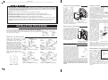
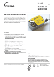
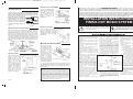
PRINTER’S INSTRUCTIONS:
INSTR,INSTL,FINISH-OUT,MC960 - LINEAR P/N: 115851 B - INK: BLACK - MATERIAL: 20 LB. MEAD BOND - SIZE: FLAT: 17.000” X 11.000”, FOLDED 8.500” X 11.000” - SCALE: 1-1 - FOLDING: 1-FOLD VERTICAL - SIDE 1 OF 2
CONTROL PANEL INSTALLATION
ANTENNA HOOKUP
Carefully remove the master unit face panel insert and
disconnect the speaker attached to it. Suspend the master
unit from the wall housing by looping the third-hand wire
(green wire) over the hook at the
top of the housing. Connect the
FM dipole twin lead to the FM 300
Ohm terminals on the tuner
module. Connect the orange AM
antenna wire to the AM terminal
on the tuner module as shown in
Figure 14 - Antenna
figure 14.
hookup
REMOTE AMPLIFIER/WIRELESS
From the 1st Power Amp, wire the MS7XSC as shown in figure 11
to the 8 pin connector P4. Connect the MS2SXSC to the two
ROOM REMOTE screws terminals as shown in figure 15. Note:
Both the blue wire and the shield wire connect to the same
terminal. Install the MCRC wireless remote control receiver in the
wall housing behind the Control Panel as shown in figure 15 by
removing the adhesive backing and pressing the MCRC firmly in
place. Route the antenna wire through the hole provided in the wall
housing. Connect the MCRC to the Control Panel as shown in
figure 15.
CONNECTING THE MCD6
Connect the Left/Right audio
RCA plugs from the MCD6 to
the
AUX1
L/R
jacks,
respectively. Connect the 2pin control cable from the
MCD6 to the jack on the
MC960
labeled
CD
INTERFACE
Figure 17 - MCD6 hookup
OTHER SOURCES
Plug in the RCA phono plugs to the
jacks as marked for the source
equipment. The figure to the right
shows a typical installation using the
AWP/AWPRX audio wall plate
installation kit.
DOOR CHIMES
Connect all Orange wires from the chimes button to the Common
terminal. Connect each
Yellow wire to each note
selection terminal. (Do not
connect more than one
Yellow wire per note
terminal.). Plug in the
chime module plug to the
4 pin connector labeled as
CHIME on the master unit.
Connect the orange &
yellow wire at each door
chime button. Set the
jumpers at P7 per chime
operation. See figure 16.
Figure 16
115851 B
INSTALLATION INSTRUCTIONS
FINISH-OUT MC960 SYSTEM
The exclamation point within an equilateral triangle is intended
to alert the user to the presence of important operating
and maintenance (servicing) instructions in the literature
accompanying the product.
Retain instructions - The safety and operating
instructions should be retained for future
reference.
After wiring has been
completed, double check
your connections and
then connect the power
cord from the TE1
transformer
to
the
Control Panel. Secure
the Control Panel to the
wall housing using the
screws
provided.
Reconnect the master
speaker and reinstall
insert. Plug-in the power
cord for each Power Amp
to a 120VAC receptacle.
If you encounter any problems, recheck all connections and check
the troubleshooting procedure in the operating instructions. If
problems still persist, contact our technical assistance center at
800-421-1587.
M&S SYSTEMS 2-YEAR "NO FAULT" LIMITED WARRANTY
M&S Systems, Inc. warrants for two years (2) all products to be free of
factory-caused defects in material and workmanship. M&S Systems,
Inc. will repair or replace, at its option, parts and materials at no
charge, regardless of the problem. This warranty extends to the original
purchaser of the product and to each subsequent owner of the product
during the term of this warranty. This NO FAULT warranty covers only
the liability described above, and does not include liability for incidental
or consequential damages. NOTE: Some states do not allow the
exclusion or limitation of incidental or consequential damages, so the
above limitation or exclusion may not apply to you.
The lightning flash with arrowhead symbol within an
equilateral triangle is intended to alert the user to the presence
of uninsulated “dangerous voltage” within the product’s
enclosure that may be of suffcient magnitude to constitute a
risk of electric shock to persons.
SAFETY INSTRUCTIONS
Read instructions - All the safety and operating
instructions should be read before the appliance
is operated.
BEFORE YOU APPLY POWER!
Figure 15
CONGRATULATIONS!
Your purchase of an M&S music system is an investment that will provide years of enjoyment and service for your
customer. M&S audio products are backed with more than 40 years of experience in the design and manufacture of
precision acoustical equipment for the home. To ensure that your customer receives the high-quality music and voice
reproduction that the system is designed to deliver, it is important that each step of the installation be done carefully. If
you follow the step-by-step illustrated instructions below, the result will be a successful professional-quality installation.
In the event you need troubleshooting assistance, please call our technical staff at 1-800-421-1587.
Heed warnings - All warnings on the appliance
and in the operating instructions should be
adhered to.
Follow instructions - All operating and use
instructions should be followed.
Water and moisture - The appliance should not
be used near water - for example; near bathtub,
washbowl, kitchen sink, laundry tub, in a wet
basement, or near a swimming pool, and the
like.
be taken so that the grounding or polarization
means of an appliance is not defeated.
Power lines - An outdoor antenna should be
located away from power lines.
Outdoor antenna grounding - If an outside
antenna is connected to the receiver, be sure
the antenna system is grounded so as to provide
some protection against voltage surges and built
up static charges. Section 810 of the National
Electrical Code, ANSI/NFPA No. 70 1984,
provides information with respect to proper
grounding of the mast and supporting structure,
grounding of the lead in wire to an antenna
discharge unit, size of grounding conductors,
location of antenna discharge unit, connection
to grounding electrodes, and requirements for
the grounding electrode. See Figure below.
Attachments - Do not use attachments not
recommended by the product manufacture
as they may cause hazards.
Ventilation - The appliance should be
situated so that its location or position does
not interfere with its proper ventilation. For
example, the appliance should not be
situated on a bed, sofa, rug, or similar
surface that may block the ventilation
openings: or, placed in a built in installation,
such as a bookcase or cabinet that may
impede the flow of air to the ventilation
openings.
Grounding or polarization - Precautions should
Damage requiring service - The appliance
should be serviced by qualified service
personnel when:
■
The power supply cord or the plug has
been damaged; or
■
objects have fallen, or liquid has been
spilled into the appliance; or
■
The appliance has been exposed to
rain; or The appliance does not appear
to operate normally or exhibits a
marked change in performance; or
■
The appliance has been dropped,
or the enclosure damaged.
■
When the product exhibits a
distinct change in performance
- this indicates a need for service.
Replacement parts - When replacement
parts are required, be sure the service
technician has used replacement parts
specified by the manufacturer or have the
same characteristics as the original part.
Unauthorized substitutions may result in
fire, electric shock, or other hazards.
Heat - The appliance should be situated
away from heat sources such as radiators,
heat registers, stoves, or other appliances
(including amplifiers) that produce heat.
Power sources - The appliance should be
connected to a power supply only of the type
described in the operating instructions or as
marked on the appliance.
Servicing - The user should not attempt to
service the appliance beyond that described in
the operating instructions. All other servicing
should be referred to qualified service
personnel.
Object and liquid entry - Never push objects
of any kind into this product through openings
as they may touch dangerous voltage points
or short out parts that could result in a fire or
electric shock. Never spill liquid of any kind on
the product.
Safety check - Upon completion of any
service or repairs to this product, ask the
service technician to perform safety checks
to determine that the product is in proper
operating condition.
Wall or ceiling mounting - The product should
be mounted to a wall or ceiling only as
recommended by the manufacturer.
PRINTER’S INSTRUCTIONS:
INSTR,INSTL,FINISH-OUT,MC960 - LINEAR P/N: 115851 B - INK: BLACK - MATERIAL: 20 LB. MEAD BOND - SIZE: FLAT: 17.000” X 11.000”, FOLDED 8.500” X 11.000” - SCALE: 1-1 - FOLDING: 1-FOLD VERTICAL - SIDE 2 OF 2
DOs & DONT's
☛ USE ONLY M&S SYSTEMS BRAND CABLE as called out in these instructions. The cable is designed and
constructed with electrical specifications necessary for proper audio performance. IMPORTANT: THE USE OF NON M&S
SYSTEMS’ BRAND CABLE OR CABLE SUBSTITUTION WILL VOID PRODUCT WARRANTY. Note: All M&S Systems’ cable has M&S
Systems and the part number printed on it!
☛ DO NOT power up master until all speakers and the amplifier are connected.
☛ DO ensure that all rough-in instructions have been followed before power is applied to system.
☛ DO NOT SPLICE CABLES. Splices are unreliable and defeat the signal isolation properties of the cable.
☛ DO NOT COIL OR BUNDLE the MS4X cable. This will cause electronic feedback.
☛ If extra cables have been run for possible future speaker additions, care must be taken that these cables do not get
connected to the control panel or amplifier unit. Unterminated cables may damage the control panel or amplifier.
☛ DO NOT over-tighten the screws for the volume controls, speakers or the control panel to prevent cracking.
INSTALLATION PROCEDURE
At each cable end, strip approximately 4 Inches of jacket (MS5XSC and MS2SXSC)
from wires and separate colored wires from each other. Strip 1/2 Inch of insulation
from each wire as shown in figure 1. On the MS7XSC, strip 1/4 Inch of insulation from
each wire as shown in figure 2.
Figure 2
SATELLITE VOLUME CONTROLS
Connect the shield wire from
outside shield of the MS5XSC to
the MS2SXSC shield wires. DO
NOT connect the shield wire for the
brown/gray pair at this end of the
cable! Wire nut each colored wire
to its respective wire as shown in
figures 3-6 for the volume control
to be used. Connect the BLUE and
VIOLET wires to the corresponding
terminals of the satellite speaker(s).
Mount the volume control to the
single gang box using the two
screws provided with the volume
control.
Figure 7 - Mounting
CONTROL HOOKUP
At
each
speaker
location,
strip
approximately 4 Inches
of
jacket
from
the
MS2SXSC cables and
separate the colored
wires from each other.
Strip 1/2 Inch of insulation
from each wire. Connect
the MS2SXSC cable to the
speaker as shown in
figure 8. NOTE: The
bare drain wire from the
cable is not connected
and should be cut off.
Figure 8 - Ceiling satellite
On speakers equipped
speaker hookup
with RED and BLACK
terminals, connect the BLUE wire to the BLACK terminal and the
VIOLET wire to the RED terminal.
Locate the MS7X5SC cable from the
Control Panel (MC960CP). Connect
each of the 7 colored wires and shield
drain wire from the MS7XSC cable to
the 8 pin terminal block as shown in
Figure 11 figure 11. Plug the 8 pin connector into MS7XSC to
the
jack
labeled
PREAMP terminal block
INTERCONNECT.
Locate
the connection
MS7X5SC cable from the second
power amplifier (MC960PA), if used. Connect each of the 7 colored
wires and shield drain wire from the MS7XSC cable to the 8 pin
terminal block as shown in figure 11. Plug the 8 pin connector into
the jack labeled TO SECOND AMP.
SATELLITE WALL SPEAKERS
WIRE PREPARATION
Figure 1 - typical
SATELLITE CEILING SPEAKERS
At each speaker location, strip
approximately 4 Inches of jacket from
the MS2SXSC cables and separate
the colored wires from each other.
Strip 1/2 Inch of insulation from each
wire. Connect the MS2SXSC cable
to the speaker as shown in figure 9.
Note: The bare drain wire from the
cable is not connected and should
be cut off. NOTE: On speakers
equipped with RED and BLACK
terminals, connect the BLUE wire to
the BLACK terminal and the VIOLET
wire to the RED terminal.
Figure 9 - Wall satellite
speaker hookup
REMOTE AMPLIFIER INSTALLATION
AMPLIFIER MOUNTING
Figure 3 - MVC96 hookup (mono)
Figure 4 - SVC96 hookup (stereo)
Figure 5 - MVC96RS hookup (mono)
Figure 6 - SVC96RS hookup (stereo)
The amplifier module will install on a
single vertical stud previously marked
during rough-in. The vertical height of the
amplifier will allow complete coverage
over the wall openings for the remote
volume controls and control panel wiring.
Mark the location of the top mounting
keyhole and bottom mounting holes. With
the amplifier removed verify the location
of the vertical stud by installing the
enclosed mounting screws at the marked
locations. Once the location of the stud
Figure 10
has been verified, remove the screws.
Remove the cover from the amplifier. While positioning the
amplifier (with cover removed) into position, bring the volume
control and preamp cabling through the holes provided. Secure the
amplifier to the wall in the marked locations with the screws provided.
FAILURE TO PROPERLY MOUNT THE AMPLIFIER MAY LEAD TO
AMPLIFIER DAMAGE AND/OR VOLUME CONTROL/PREAMP WIRING
DAMAGE.
Locate MS2SXSC cable from the Power Amp and connect the
BLUE and VIOLET wires to their respective terminals on the Power
Amp as shown in figure 12. Note: If additional Power Amps are
used, connect the shield drain wire of both the MS2SXSC cables
from the Control Panel and
the additional Power Amp
together using a wire nut.
Locate MS2SXSC cable
from the Control Panel
and connect the Blue &
Violet wires to their
respective
terminals
on the Power Amp as
shown in Figure 12.
Note: The bare shield
wire from the MS2SXSC
is not connected and
should be cut off, unless
additional Power Amps
are used. In this case,
connect the shield wire
going to the next Power
Amp, to the drain wire
from the Control Panel.
Figure 12 - Amplifier module hookup
Gather
all
volume
control cables (MS5XSC). Pigtail all shield drain wires (bare) from
the MS5XSC cables to the SHIELD terminal on the remote
amplifier. Then connect each of the color coded wires to its
respective terminals as shown in Figure 12.
STEREO/MONO CONFIGURATION
Each
MC960PA remote
amplifier is equipped with
a
stereo/mono
select
jumper.
All
MC960PA
amplifiers
are
shipped
from the factory with this
jumper in the STEREO
position. If an amplifier is
required to drive more than
10 monaural speakers, this
Figure 13 - Mono/Stereo
jumper must be set to the
jumper
MONO position. Setting
the jumper to the MONO position will cause monaural
output to all speakers whether they are connected via
stereo controls or mono controls. The jumper setting of
one MC960PA amplifier has no effect on other MC960PA
amplifiers.
PRINTER’S INSTRUCTIONS:
INSTR,INSTL,FINISH-OUT,MC960 - LINEAR P/N: 115851 B - INK: BLACK - MATERIAL: 20 LB. MEAD BOND - SIZE: FLAT: 17.000” X 11.000”, FOLDED 8.500” X 11.000” - SCALE: 1-1 - FOLDING: 1-FOLD VERTICAL - SIDE 1 OF 2
CONTROL PANEL INSTALLATION
ANTENNA HOOKUP
Carefully remove the master unit face panel insert and
disconnect the speaker attached to it. Suspend the master
unit from the wall housing by looping the third-hand wire
(green wire) over the hook at the
top of the housing. Connect the
FM dipole twin lead to the FM 300
Ohm terminals on the tuner
module. Connect the orange AM
antenna wire to the AM terminal
on the tuner module as shown in
Figure 14 - Antenna
figure 14.
hookup
REMOTE AMPLIFIER/WIRELESS
From the 1st Power Amp, wire the MS7XSC as shown in figure 11
to the 8 pin connector P4. Connect the MS2SXSC to the two
ROOM REMOTE screws terminals as shown in figure 15. Note:
Both the blue wire and the shield wire connect to the same
terminal. Install the MCRC wireless remote control receiver in the
wall housing behind the Control Panel as shown in figure 15 by
removing the adhesive backing and pressing the MCRC firmly in
place. Route the antenna wire through the hole provided in the wall
housing. Connect the MCRC to the Control Panel as shown in
figure 15.
CONNECTING THE MCD6
Connect the Left/Right audio
RCA plugs from the MCD6 to
the
AUX1
L/R
jacks,
respectively. Connect the 2pin control cable from the
MCD6 to the jack on the
MC960
labeled
CD
INTERFACE
Figure 17 - MCD6 hookup
OTHER SOURCES
Plug in the RCA phono plugs to the
jacks as marked for the source
equipment. The figure to the right
shows a typical installation using the
AWP/AWPRX audio wall plate
installation kit.
DOOR CHIMES
Connect all Orange wires from the chimes button to the Common
terminal. Connect each
Yellow wire to each note
selection terminal. (Do not
connect more than one
Yellow wire per note
terminal.). Plug in the
chime module plug to the
4 pin connector labeled as
CHIME on the master unit.
Connect the orange &
yellow wire at each door
chime button. Set the
jumpers at P7 per chime
operation. See figure 16.
Figure 16
115851 B
INSTALLATION INSTRUCTIONS
FINISH-OUT MC960 SYSTEM
The exclamation point within an equilateral triangle is intended
to alert the user to the presence of important operating
and maintenance (servicing) instructions in the literature
accompanying the product.
Retain instructions - The safety and operating
instructions should be retained for future
reference.
After wiring has been
completed, double check
your connections and
then connect the power
cord from the TE1
transformer
to
the
Control Panel. Secure
the Control Panel to the
wall housing using the
screws
provided.
Reconnect the master
speaker and reinstall
insert. Plug-in the power
cord for each Power Amp
to a 120VAC receptacle.
If you encounter any problems, recheck all connections and check
the troubleshooting procedure in the operating instructions. If
problems still persist, contact our technical assistance center at
800-421-1587.
M&S SYSTEMS 2-YEAR "NO FAULT" LIMITED WARRANTY
M&S Systems, Inc. warrants for two years (2) all products to be free of
factory-caused defects in material and workmanship. M&S Systems,
Inc. will repair or replace, at its option, parts and materials at no
charge, regardless of the problem. This warranty extends to the original
purchaser of the product and to each subsequent owner of the product
during the term of this warranty. This NO FAULT warranty covers only
the liability described above, and does not include liability for incidental
or consequential damages. NOTE: Some states do not allow the
exclusion or limitation of incidental or consequential damages, so the
above limitation or exclusion may not apply to you.
The lightning flash with arrowhead symbol within an
equilateral triangle is intended to alert the user to the presence
of uninsulated “dangerous voltage” within the product’s
enclosure that may be of suffcient magnitude to constitute a
risk of electric shock to persons.
SAFETY INSTRUCTIONS
Read instructions - All the safety and operating
instructions should be read before the appliance
is operated.
BEFORE YOU APPLY POWER!
Figure 15
CONGRATULATIONS!
Your purchase of an M&S music system is an investment that will provide years of enjoyment and service for your
customer. M&S audio products are backed with more than 40 years of experience in the design and manufacture of
precision acoustical equipment for the home. To ensure that your customer receives the high-quality music and voice
reproduction that the system is designed to deliver, it is important that each step of the installation be done carefully. If
you follow the step-by-step illustrated instructions below, the result will be a successful professional-quality installation.
In the event you need troubleshooting assistance, please call our technical staff at 1-800-421-1587.
Heed warnings - All warnings on the appliance
and in the operating instructions should be
adhered to.
Follow instructions - All operating and use
instructions should be followed.
Water and moisture - The appliance should not
be used near water - for example; near bathtub,
washbowl, kitchen sink, laundry tub, in a wet
basement, or near a swimming pool, and the
like.
be taken so that the grounding or polarization
means of an appliance is not defeated.
Power lines - An outdoor antenna should be
located away from power lines.
Outdoor antenna grounding - If an outside
antenna is connected to the receiver, be sure
the antenna system is grounded so as to provide
some protection against voltage surges and built
up static charges. Section 810 of the National
Electrical Code, ANSI/NFPA No. 70 1984,
provides information with respect to proper
grounding of the mast and supporting structure,
grounding of the lead in wire to an antenna
discharge unit, size of grounding conductors,
location of antenna discharge unit, connection
to grounding electrodes, and requirements for
the grounding electrode. See Figure below.
Attachments - Do not use attachments not
recommended by the product manufacture
as they may cause hazards.
Ventilation - The appliance should be
situated so that its location or position does
not interfere with its proper ventilation. For
example, the appliance should not be
situated on a bed, sofa, rug, or similar
surface that may block the ventilation
openings: or, placed in a built in installation,
such as a bookcase or cabinet that may
impede the flow of air to the ventilation
openings.
Grounding or polarization - Precautions should
Damage requiring service - The appliance
should be serviced by qualified service
personnel when:
■
The power supply cord or the plug has
been damaged; or
■
objects have fallen, or liquid has been
spilled into the appliance; or
■
The appliance has been exposed to
rain; or The appliance does not appear
to operate normally or exhibits a
marked change in performance; or
■
The appliance has been dropped,
or the enclosure damaged.
■
When the product exhibits a
distinct change in performance
- this indicates a need for service.
Replacement parts - When replacement
parts are required, be sure the service
technician has used replacement parts
specified by the manufacturer or have the
same characteristics as the original part.
Unauthorized substitutions may result in
fire, electric shock, or other hazards.
Heat - The appliance should be situated
away from heat sources such as radiators,
heat registers, stoves, or other appliances
(including amplifiers) that produce heat.
Power sources - The appliance should be
connected to a power supply only of the type
described in the operating instructions or as
marked on the appliance.
Servicing - The user should not attempt to
service the appliance beyond that described in
the operating instructions. All other servicing
should be referred to qualified service
personnel.
Object and liquid entry - Never push objects
of any kind into this product through openings
as they may touch dangerous voltage points
or short out parts that could result in a fire or
electric shock. Never spill liquid of any kind on
the product.
Safety check - Upon completion of any
service or repairs to this product, ask the
service technician to perform safety checks
to determine that the product is in proper
operating condition.
Wall or ceiling mounting - The product should
be mounted to a wall or ceiling only as
recommended by the manufacturer.