1
Dominion PX
User Guide
Release 1.3.5
Copyright © 2010 Raritan, Inc.
DPX-0L-v1.3.5-E
April 2010
255-80-6080-00
Safety Guidelines
WARNING! Read and understand all sections in this guide before installing or operating this product.
WARNING! Connect this product to an AC power source whose voltage is within the range specified on
the product’s nameplate. Operating this product outside the nameplate voltage range may result in
electric shock, fire, personal injury and death.
WARNING! Connect this product to an AC power source that is current limited by a suitably rated fuse
or circuit breaker in accordance with national and local electrical codes. Operating this product without
proper current limiting may result in electric shock, fire, personal injury and death.
WARNING! Connect this product to a protective earth ground. Never use a “ground lift adaptor”
between the product’s plug and the wall receptacle. Failure to connect to a protective earth ground may
result in electric shock, fire, personal injury and death.
WARNING! This product contains no user serviceable parts. Do not open, alter or disassemble this
product. All servicing must be performed by qualified personnel. Disconnect power before servicing this
product. Failure to comply with this warning may result in electric shock, personal injury and death.
WARNING! Use this product in a dry location. Failure to use this product in a dry location may result in
electric shock, personal injury and death.
WARNING! Do not rely on this product’s receptacle lamps, receptacle relay switches or any other
receptacle power on/off indicator to determine whether power is being supplied to a receptacle. Unplug
a device connected to this product before performing repair, maintenance or service on the device.
Failure to unplug a device before servicing it may result in electric shock, fire, personal injury and death.
WARNING! Only use this product to power information technology equipment that has a UL/IEC
60950-1 or equivalent rating. Attempting to power non rated devices may result in electric shock, fire,
personal injury and death.
WARNING! Do not use this product to power inductive loads such as motors or compressors.
Attempting to power inductive loads may result in damage to the product.
WARNING! Do not use this product to power critical patient care equipment, fire or smoke alarm
systems. Use of this product to power such equipment may result in personal injury and death.
WARNING! If this product is a model that requires assembly of its line cord or plug, all such assembly
must be performed by a licensed electrician and the line cord or plugs used must be suitably rated
based on the product’s nameplate ratings and national and local electrical codes. Assembly by
unlicensed electricians or failure to use suitably rated line cords or plugs may result in electric shock,
fire, personal injury or death.
WARNING! This product contains a chemical known to the State of California to cause cancer, birth
defects, or other reproductive harm.
Safety Instructions
1. Installation of this product should only be performed by a person who has knowledge and
experience with electric power.
2. Make sure the line cord is disconnected from power before physically mounting or moving the
location of this product.
3. This product is designed to be used within an electronic equipment rack. The metal case of this
product is electrically bonded to the line cord ground wire. A threaded grounding point on the case
may be used as an additional means of protectively grounding this product and the rack.
4. Examine the branch circuit receptacle that will supply electric power to this product. Make sure the
receptacle’s power lines, neutral and protective earth ground pins are wired correctly and are the
correct voltage and phase. Make sure the branch circuit receptacle is protected by a suitably rated
fuse or circuit breaker.
5. If the product is a model that contains receptacles that can be switched on/off, electric power may
still be present at a receptacle even when it is switched off.
This document contains proprietary information that is protected by copyright. All rights reserved. No
part of this document may be photocopied, reproduced, or translated into another language without
express prior written consent of Raritan, Inc.
© Copyright 2010 Raritan, Inc., CommandCenter®, Dominion®, Paragon® and the Raritan company
logo are trademarks or registered trademarks of Raritan, Inc. All rights reserved. Java® is a registered
trademark of Sun Microsystems, Inc. Internet Explorer® is a registered trademark of Microsoft
Corporation. Netscape® and Netscape Navigator® are registered trademarks of Netscape
Communication Corporation. All other trademarks or registered trademarks are the property of their
respective holders.
FCC Information
This equipment has been tested and found to comply with the limits for a Class A digital device,
pursuant to Part 15 of the FCC Rules. These limits are designed to provide reasonable protection
against harmful interference in a commercial installation. This equipment generates, uses, and can
radiate radio frequency energy and if not installed and used in accordance with the instructions, may
cause harmful interference to radio communications. Operation of this equipment in a residential
environment may cause harmful interference.
VCCI Information (Japan)
Raritan is not responsible for damage to this product resulting from accident, disaster, misuse, abuse,
non-Raritan modification of the product, or other events outside of Raritan's reasonable control or not
arising under normal operating conditions.
Contents
Safety Guidelines
ii
Safety Instructions
iii
Chapter 1 Introduction
1
Product Models .............................................................................................................................. 1
Product Photos .............................................................................................................................. 1
Zero U Size.......................................................................................................................... 2
1U Size ................................................................................................................................ 2
2U Size ................................................................................................................................ 3
Product Features ........................................................................................................................... 3
Package Contents.......................................................................................................................... 4
Zero U Products................................................................................................................... 5
1U Products ......................................................................................................................... 5
2U Products ......................................................................................................................... 5
Chapter 2 Rack-Mounting Dominion PX
6
Rackmount Safety Guidelines ....................................................................................................... 6
Standard Rackmount ..................................................................................................................... 6
Mounting Zero U Models Using L-Bracket.....................................................................................8
For Zero U Models Using Tool-less Button Mounting.................................................................... 9
Before You Begin Tool-less Mounting:................................................................................9
Mounting Zero U Models Using Button Mount ..................................................................10
Mounting Zero U Models Using Claw-Foot Bracket ....................................................................12
Chapter 3 Installation and Configuration
14
Before You Begin......................................................................................................................... 14
Unpacking the Product and Components..........................................................................14
Preparing the Installation Site............................................................................................14
Filling Out the Equipment Setup Worksheet .....................................................................14
Configuring Dominion PX ............................................................................................................ 15
Connecting Dominion PX to a Computer ..........................................................................15
Connecting Dominion PX to Your Network .......................................................................16
Initial Network Configuration..............................................................................................17
v
Contents
Resetting to Factory Defaults ...................................................................................................... 20
Chapter 4 Using Dominion PX
22
Panel Components ...................................................................................................................... 22
Blue LED............................................................................................................................ 22
Power Cord........................................................................................................................ 22
Outlets ............................................................................................................................... 23
Connection Ports ...............................................................................................................23
LED Display ....................................................................................................................... 24
Reset Button ...................................................................................................................... 26
Circuit Breaker ............................................................................................................................. 26
Resetting the Button-Type Circuit Breaker........................................................................27
Resetting the Handle-Type Circuit Breaker.......................................................................27
Beeper ......................................................................................................................................... 28
Measurement Accuracy ............................................................................................................... 28
Chapter 5 Using the Web Interface
29
Logging in to the Web Interface................................................................................................... 29
Login .................................................................................................................................. 29
Changing Your Password..................................................................................................32
Web Interface Elements .............................................................................................................. 33
Menus ................................................................................................................................ 33
Navigation Path ................................................................................................................. 34
Status Panel ...................................................................................................................... 35
Status Messages ...............................................................................................................37
Unavailable Options ..........................................................................................................37
Reset to Defaults ............................................................................................................... 37
Refresh .............................................................................................................................. 38
Using the Home Window ............................................................................................................. 38
Line Loads Display ............................................................................................................38
Circuit Breaker Status........................................................................................................39
Outlets List......................................................................................................................... 40
All Outlets Control.............................................................................................................. 41
Monitoring Line and Circuit Breaker Status .................................................................................41
Monitoring Unbalanced Loads...........................................................................................42
Line Details Page ..............................................................................................................44
Circuit Breaker Details Page .............................................................................................44
Setting Up User Profiles .............................................................................................................. 45
Creating a User Profile ......................................................................................................45
Copying a User Profile.......................................................................................................47
Modifying a User Profile ....................................................................................................47
Deleting a User Profile.......................................................................................................48
Setting User Permissions Individually ...............................................................................48
Setting Up User Groups............................................................................................................... 49
Creating a User Group ......................................................................................................50
Setting System Permissions..............................................................................................50
Setting Outlet Permissions ................................................................................................52
Copying a User Group.......................................................................................................53
vi
Contents
Modifying a User Group.....................................................................................................53
Deleting a User Group.......................................................................................................54
Access Security Control............................................................................................................... 54
Forcing HTTPS Encryption................................................................................................54
Configuring the Firewall.....................................................................................................55
Creating Group Based Access Control Rules ...................................................................58
Setting Up User Login Controls .........................................................................................61
Setting Up a Digital Certificate..................................................................................................... 65
Creating a Certificate Signing Request .............................................................................66
Installing a Certificate ........................................................................................................ 68
Setting Up External User Authentication .....................................................................................68
Gathering Information for LDAP Configuration..................................................................69
Setting Up LDAP Authentication........................................................................................70
Setting Up RADIUS Authentication ...................................................................................72
Setting Up Outlets and Power Thresholds ..................................................................................73
Setting the Global Default Outlet State .............................................................................74
Setting the Global Power Cycling Delay............................................................................75
Setting the Hysteresis for Outlet Thresholds.....................................................................75
Setting PDU Thresholds ....................................................................................................76
Setting the Outlet Power-On Sequence ............................................................................76
Naming Outlets .................................................................................................................. 77
Setting Outlet Thresholds ..................................................................................................78
Viewing Outlet Details .......................................................................................................79
Power Cycling an Outlet ....................................................................................................80
Turning an Outlet On or Off ...............................................................................................80
Environmental Sensors................................................................................................................ 80
Connecting Environmental Sensors ..................................................................................81
Mapping Environmental Sensors.......................................................................................83
Configuring Environmental Sensors and Thresholds ........................................................ 85
Describing Environmental Sensor Location ......................................................................86
Viewing Sensor Readings .................................................................................................87
Configuring and Using Alert Notifications ....................................................................................88
Components of an Alert.....................................................................................................88
How to Configure an Alert .................................................................................................88
Sample Alerts .................................................................................................................... 96
A Note about Untriggered Alerts........................................................................................98
Setting Up Event Logging ..........................................................................................................100
Configuring the Local Event Log .....................................................................................101
Viewing Internal Event Log..............................................................................................103
Configuring NFS Logging ................................................................................................104
Configuring SMTP Logging .............................................................................................105
Configuring SNMP Logging .............................................................................................106
Configuring Syslog Forwarding .......................................................................................106
Managing Dominion PX ............................................................................................................. 107
Displaying Basic Device Information ...............................................................................107
Displaying Model Configuration Information....................................................................109
Displaying Connected Users ...........................................................................................109
Naming the Dominion PX Device ....................................................................................110
Modifying Network Settings .............................................................................................111
Modifying Network Service Settings ................................................................................112
Modifying LAN Interface Settings ....................................................................................113
Setting the Date and Time...............................................................................................114
vii
Contents
Configuring SMTP Settings .............................................................................................115
Configuring SNMP Settings.............................................................................................116
Enabling Data Retrieval...................................................................................................117
Resetting the Dominion PX Device .................................................................................118
Updating the Firmware ....................................................................................................120
Copying Configurations with Bulk Configuration .............................................................122
Outlet Grouping..........................................................................................................................125
Identifying Other Dominion PX Devices ..........................................................................125
Grouping Outlets Together ..............................................................................................126
Viewing and Controlling Outlet Groups ...........................................................................127
Editing or Deleting Outlet Groups....................................................................................128
Deleting Outlet Group Devices ........................................................................................128
Chapter 6 Integration
130
Dominion KX I Power Strip Configuration..................................................................................131
Setup Preparation............................................................................................................132
Connecting the Power Strip.............................................................................................132
Configuring the Power Strip.............................................................................................132
KX Manager Application ..................................................................................................133
Associating Outlets with a Target ....................................................................................134
Controlling a Target's Power ...........................................................................................135
Dominion KX II Power Strip Configuration.................................................................................136
Configuring Power Strip (Rack PDU) Targets .................................................................136
Paragon II ..................................................................................................................................141
Paragon Manager Application .........................................................................................142
Adding a Dominion PX in Paragon II...............................................................................142
Associating Outlets with a Target ....................................................................................143
Controling a Target's Power ............................................................................................143
Controling an Outlet's Power...........................................................................................144
Dominion SX ..............................................................................................................................144
Configuring a Dominion PX on Dominion SX ..................................................................144
Power Control ..................................................................................................................145
Checking Power Strip Status...........................................................................................146
Dominion KSX............................................................................................................................146
CommandCenter Secure Gateway............................................................................................147
Direct Control from CC-SG 4.0........................................................................................147
viii
Contents
Appendix A Specifications
148
Environmental Specifications.....................................................................................................148
Dominion PX Serial RJ-45 Port Pinouts ....................................................................................148
Dominion PX Feature RJ-12 Port Pinouts .................................................................................148
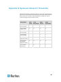
Appendix B Equipment Setup Worksheet
150
Appendix C Using the CLP Interface
154
About the CLP Interface ............................................................................................................154
Logging in to the CLP interface .................................................................................................154
With HyperTerminal.........................................................................................................155
With SSH or Telnet..........................................................................................................156
Closing a Serial Connection ............................................................................................157
Showing Outlet Information .......................................................................................................157
Syntax..............................................................................................................................158
Attributes..........................................................................................................................158
Examples .........................................................................................................................158
Showing In-Depth Outlet Information.........................................................................................159
Outlet Sensor Properties .................................................................................................160
Examples of Showing In-Depth Outlet Information .........................................................160
Switching an Outlet ....................................................................................................................161
Turning an Outlet On .......................................................................................................161
Turning an Outlet Off .......................................................................................................161
Querying an Outlet Sensor ........................................................................................................162
Setting the Sequence Delay ......................................................................................................162
Resetting the Dominion PX Device............................................................................................162
Appendix D Using SNMP
163
Enabling SNMP..........................................................................................................................164
Configuring Users for Encrypted SNMP v3 .....................................................................166
Restarting the SNMP Agent after Adding Users .............................................................167
Configuring SNMP Traps...........................................................................................................167
SNMP Gets and Sets.................................................................................................................169
The Dominion PX MIB .....................................................................................................169
Disabling Outlet Switching...............................................................................................171
Retrieving Energy Usage.................................................................................................171
Appendix E Using the IPMI Tool Set
172
Channel Commands ..................................................................................................................172
authcap <channel number> <max priv>..........................................................................172
info [channel number] ......................................................................................................173
getaccess <channel number> [userid] ............................................................................173
ix
Contents
setaccess <channel number> <userid>[callin=on|off] [ipmi=on|off] [link=on|off]
[privilege=level]................................................................................................................173
getciphers <all | supported> <ipmi | sol> [channel] .........................................................173
Event Commands ......................................................................................................................173
<predefined event number> ............................................................................................174
file <filename> .................................................................................................................174
LAN Commands.........................................................................................................................174
print <channel> ................................................................................................................174
set <channel> <parameter> ............................................................................................175
Sensor Commands ....................................................................................................................176
list ....................................................................................................................................176
get <id> ... [<id>].............................................................................................................. 176
thresh <id> <threshold> <setting>...................................................................................176
OEM Commands .......................................................................................................................177
A Note About Group Commands.....................................................................................177
Set Power On Delay Command ......................................................................................178
Get Power On Delay Command ......................................................................................178
Set Receptacle State Command .....................................................................................178
Get Receptacle State Command.....................................................................................178
Get Receptacle State and Data Command .....................................................................179
Set Group State Command .............................................................................................180
Set Group Membership Command..................................................................................180
Get Group Membership Command .................................................................................181
Set Group Power On Delay Command ...........................................................................181
Get Group Power On Delay Command...........................................................................182
Set Receptacle ACL ........................................................................................................182
Get Receptacle ACL........................................................................................................182
Test Actors.......................................................................................................................183
Test Sensors....................................................................................................................183
Set Power Cycle Delay Command ..................................................................................183
Get Power Cycle Delay Command..................................................................................183
IPMI Privilege Levels .................................................................................................................184
Appendix F Event Types
186
Appendix G Hysteresis Values for Thresholds
187
Index
189
x
Chapter 1
Introduction
Dominion PX is an intelligent power distribution unit (PDU) that allows you
to reboot remote servers and other network devices and/or to monitor
power in the data center.
The intended use of the Raritan Dominion PX is distribution of power to
information technology equipment such as computers and communication
equipment where such equipment is typically mounted in an equipment
rack located in an information technology equipment room.
Raritan offers different types of PDUs -- some with the outlet switching
function, and others without. With the outlet switching function, you can
recover systems remotely in the event of system failure and/or system
lockup, eliminate the need to perform manual intervention or dispatch field
personnel, reduce downtime and mean time to repair, and increase
productivity.
In This Chapter
Product Models..........................................................................................1
Product Photos ..........................................................................................1
Product Features .......................................................................................3
Package Contents .....................................................................................4
Product Models
Dominion PX comes in several models that are built to stock and can be
obtained almost immediately. Raritan also offers custom models that are
built to order and can only be obtained on request.
Visit Raritan website (http://www.raritan.com) or contact your local
reseller for a list of available models.
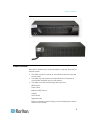
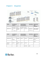
Product Photos
Dominion PX comes in Zero U, 1U, and 2U sizes.
1
Chapter 1: Introduction
Zero U Size
1U Size
2
Chapter 1: Introduction
2U Size
Product Features
Dominion PX models vary in sizes and features. In general, Dominion PX
features include:
•
The ability to power on, power off, and reboot the devices connected
to each outlet
•
The ability to group outlets from multiple Dominion PX devices as
virtual outlets accessible from a single session
•
The ability to monitor the following at the outlet level:
RMS Current
Power Factor
Maximum RMS Current
Voltage
Active Power
Apparent Power
Energy Consumption (Active Energy) on some models (part numbers
follow PX-nnnn format)
3
Chapter 1: Introduction
•
The ability to monitor the internal CPU temperature of the Dominion
PX device
•
The ability to monitor environmental factors such as external
temperature and humidity
•
User-specified location attributes for environmental sensors
•
An audible alarm (beeper) and a visual alarm (blinking LED) to
indicate current overload
•
Configurable alarm thresholds
•
Support for SNMP v1, v2, and v3
•
The ability to send traps using SNMP protocol
•
The ability to retrieve outlet specific data using SNMP, including outlet
state, current, voltage, and power
•
The ability to retrieve a history of sampled data at all levels (unit,
circuit breaker, outlet, etc) via SNMP
•
The ability to configure and set values through SNMP, including unit
and outlet threshold levels
•
The ability to save one Dominion PX device's configuration settings
and then deploy those settings to other Dominion PX devices
•
Fully shrouded local branch circuit breakers on products rated over
20A to protect connected equipment against overload and short
circuits
•
Integration with Raritan's Paragon II, CommandCenter Secure
Gateway (CC-SG), and Dominion access devices
•
Line current and circuit breaker monitoring
•
Load imbalance calculations, for 3-phase models
•
A combination of outlet types (for example, C13 and C19 outlets) in
select models
•
A combination of outlet voltages (120 and 208 volts) in select models
•
Support for high current devices (such as Blade Servers) in select
models
Note: Select models may be available without outlet switching. Please
check with your reseller or distributor.
Package Contents
The following describes the equipment and other material included in the
product package.
4
Chapter 1: Introduction
Zero U Products
•
Dominion PX device
•
Bracket for Zero U and screws
•
Tool-less mounting bracket for Zero U devices
•
Null-modem cable with RJ-45 and DB9F connectors on either end
1U Products
•
Dominion PX device
•
1U bracket pack and screws
•
Null-modem cable with RJ-45 and DB9F connectors on either end
2U Products
•
Dominion PX device
•
2U bracket pack and screws
•
Null-modem cable with RJ-45 and DB9F connectors on either end
5
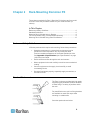
Chapter 2
Rack-Mounting Dominion PX
The rackmount methods for Zero U Dominion PX devices vary from model
to model. Follow the procedure suitable for your model and rack (or
cabinet).
In This Chapter
Rackmount Safety Guidelines ...................................................................6
Standard Rackmount.................................................................................6
Mounting Zero U Models Using L-Bracket ................................................8
For Zero U Models Using Tool-less Button Mounting ...............................9
Mounting Zero U Models Using Claw-Foot Bracket ................................12
Rackmount Safety Guidelines
In Raritan products which require rack mounting, follow these precautions:
Operation temperature in a closed rack environment may be
greater than room temperature. Do not exceed the rated
maximum ambient temperature of the Power Distribution Units.
See Appendix A: Specifications (see "Specifications" on page
148) in the User Guide.
Ensure sufficient airflow through the rack environment.
Mount equipment in the rack carefully to avoid uneven mechanical
loading.
Connect equipment to the supply circuit carefully to avoid
overloading circuits.
Ground all equipment properly, especially supply connections, to
the branch circuit.
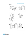
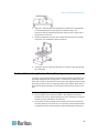
Standard Rackmount
The Zero U units are provided with high grade
engineering polycarbonate isolation hardware
to allow fixing in a variety of positions within
the rack.
For panel/flush mount, pull out fixing brackets
are available on each end cap to allow
mounting on suitable rails.
See other options shown below.
6
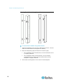
Chapter 2: Rack-Mounting Dominion PX
Side Fixing
Blind Fixing
7
Chapter 2: Rack-Mounting Dominion PX
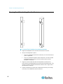
Mounting Zero U Models Using L-Bracket
To mount Zero U models using L-Bracket:
1. Align the baseplates on the rear of the Dominion PX device.
2. Secure the baseplates in place. Different models ship with different
types of baseplates.
8
To secure a baseplate with the thumbscrew, turn the thumbscrew
until it is tightened.
To secure a baseplate without the thumbscrew, use the included
L-shaped hex key to loosen the hex socket screws until the
baseplate is fastened.
Chapter 2: Rack-Mounting Dominion PX
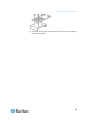
3. Align the L-brackets with the baseplates so that the five screw-holes
on the baseplates line up through the L-Bracket's slots. The
rackmount side of brackets should face either the left or right side of
the Dominion PX device.
4. Fasten the brackets in place with at least three screws (one through
each slot). Use additional screws as desired.
5. Using rack screws, fasten the Dominion PX device to the rack through
the L-Brackets.
For Zero U Models Using Tool-less Button Mounting
The Zero U devices ship with tool-less mounting brackets consisting of an
adjustable baseplate with a large button. These work by attaching to the
back side of a Zero U Dominion PX device (the side opposite of the outlets)
and fitting the button into the mounting holes of the cabinet. Note that not
all racks may allow the option of securing the Dominion PX device in this
way.
Before You Begin Tool-less Mounting:
•
Ensure that you have sufficient space in the cabinet to mount the
Dominion PX device. Approximately one inch of clearance is required
at each end (top and bottom) of the device.
•
It may help to mark the back of the Dominion PX device through the
mounting holes you intend to use. You can then use this mark to assist
in aligning the silver buttons properly when attaching the base-plate.
9
Chapter 2: Rack-Mounting Dominion PX
Mounting Zero U Models Using Button Mount
To mount Zero-U models using button mount:
1. Align the baseplates on the rear of the Dominion PX device. Leave at
least 24 inches between the baseplates for stability.
2. Make the baseplates grasp the Dominion PX device lightly.
For a baseplate with the thumbscrew, turn the thumbscrew until it
is "slightly" tightened.
For a baseplate without the thumbscrew, use the included
L-shaped hex key to loosen the hex socket screws until the
baseplate is "slightly" fastened.
3. Screw each mounting button in the center of each baseplate.
10
Chapter 2: Rack-Mounting Dominion PX
4. Align the large mounting buttons with the mounting holes in the
cabinet, fixing one in place and adjusting the other.
5. Depending on the type of your baseplates, either further tighten the
thumbscrews or loosen the hex socket screws until the mounting
buttons are secured in their position.
6. Ensure that both buttons can engage their mounting holes
simultaneously.
7. Press the Dominion PX device forward, pushing the mounting buttons
through the mounting holes, then letting the device drop about 5/8".
This secures the Dominion PX device in place and completes the
installation.
11
Chapter 2: Rack-Mounting Dominion PX
Mounting Zero U Models Using Claw-Foot Bracket
To mount Zero U models using claw-foot brackets:
1. Align the baseplates on the rear of the Dominion PX device.
2. Secure the baseplates in place.
To secure a baseplate with the thumbscrew, turn the thumbscrew
until it is tightened.
To secure a baseplate without the thumbscrew, use the included
L-shaped hex key to loosen the hex socket screws until the
baseplate is fastened.
3. Align the claw-foot brackets with the baseplates so that the five
screw-holes on the baseplates line up through the bracket's slots. The
rackmount side of brackets should face either the left or right side of
the Dominion PX device.
4. Fasten the brackets in place with at least three screws (one through
each slot). Use additional screws as desired.
12
Chapter 2: Rack-Mounting Dominion PX
5. Using rack screws, fasten the Dominion PX device to the rack through
the claw-foot brackets.
13
Chapter 3
Installation and Configuration
This chapter explains how to install a Dominion PX device and configure it
for network connectivity.
In This Chapter
Before You Begin ....................................................................................14
Configuring Dominion PX ........................................................................15
Resetting to Factory Defaults ..................................................................20
Before You Begin
Before beginning the installation, perform the following activities:
Unpacking the Product and Components
1. Remove the Dominion PX device and other equipment from the box in
which they were shipped. See Package Contents for a complete list of
the contents of the box.
2. Compare the serial number of the equipment with the number on the
packing slip located on the outside of the box and make sure they
match.
3. Inspect the equipment carefully. If any of the equipment is damaged or
missing, contact Raritan's Technical Support Department for
assistance.
Preparing the Installation Site
1. Make sure the installation area is clean and free of extreme
temperatures and humidity.
2. Allow sufficient space around the Dominion PX device for cabling and
outlet connections.
3. Review the Safety Instructions (on page iii) listed in the beginning of
this user guide.
Filling Out the Equipment Setup Worksheet
An Equipment Setup Worksheet is provided in this guide. See Equipment
Setup Worksheet (on page 150). Use this worksheet to record the model,
serial number, and use of each device connected to Dominion PX.
As you add and remove devices, keep the worksheet up to date.
14
Chapter 3: Installation and Configuration
Configuring Dominion PX
You must connect the Dominion PX device to a computer to configure it,
using a serial connection between Dominion PX and the computer.
The computer must have a communications program such as
HyperTerminal or PuTTY. In addition, you need a null-modem cable with
RJ-45 and DB9F connectors on either end.
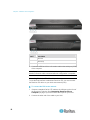
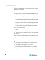
Connecting Dominion PX to a Computer
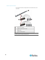
To connect the PDU to the computer:
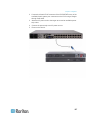
1. Connect the RJ-45 end of the null-modem cable to the port labeled
Serial on the front of the Dominion PX device.
15
Chapter 3: Installation and Configuration
Item #
Description
1
LAN Port
2
Serial Port
3
Network Port
2. Connect the DB9 end of the null-modem cable to the serial port (COM)
of the computer.
Note: If you plan to use the serial connection to log in to the command line
interface, leave the cable connected after the configuration is complete.
Connecting Dominion PX to Your Network
To use the web interface to administer Dominion PX, you must connect
the Dominion PX device to your local area network (LAN).
To connect the PDU to the network:
1. Connect a standard Cat 5e UTP cable to the LAN port on the front of
the Dominion PX device. See Connecting Dominion PX to a
Computer (on page 15) for the location of this port on your PDU.
2. Connect the other end of the cable to your LAN.
16
Chapter 3: Installation and Configuration
Initial Network Configuration
After the Dominion PX device is connected to your network, you must
provide it with an IP address and some additional networking information.
To configure the networking parameters:
1. Go to the computer that you connected to the Dominion PX device
and open a communications program such as HyperTerminal or
PuTTY.
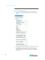
2. Select the appropriate serial port, and make sure the port settings are
configured as follows:
Bits per second = 9600
Data bits = 8
Stop bits = 1
Parity = None
Flow control = None
Note: The “Flow control” parameter must be set to “None” to ensure
that the communications program will work correctly with Dominion
PX.
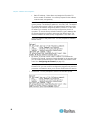
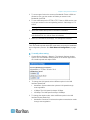
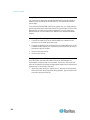
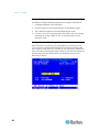
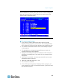
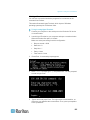
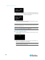
3. Press Enter to display the opening configuration prompt.
4. Type config and press Enter to begin the configuration process. You
are prompted to select an IP configuration method.
5. You must assign the Dominion PX device an IP address. There are
two ways to do this:
Auto configuration - Select an autoconfiguration method such as
dhcp or bootp and let the DHCP or BOOTP server provide the IP
address.
17
Chapter 3: Installation and Configuration
Static IP address - Select None and assign the Dominion PX
device a static IP address. You will be prompted for the address,
network mask, and gateway.
Note: Dominion PX's IP address is automatically displayed in the
system prompt. The default IP address is 192.168.0.192. The default
IP configuration method is DHCP, and the default IP address will be
replaced by the address assigned by DHCP or BOOTP, or the static
IP address you entered, as soon as the configuration process is
complete. To use the factory default IP address, type in none as the
IP autoconfiguration command, and accept the default value. The
default IP address for static (none) configuration is 192.168.0.192.
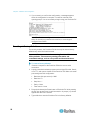
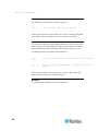
Type your selection and press Enter. You are prompted to enable IP
access control.
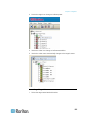
6. By default, IP access control is NOT enabled. This disables the
Dominion PX firewall. Leave the firewall disabled for the present; later
you will enable the firewall from the web interface and create firewall
rules. See Configuring the Firewall (on page 55).
Note: If you ever accidentally create a rule that locks you out of
Dominion PX, you can rerun the configuration program and reset this
parameter to disabled to allow you to access the Dominion PX device.
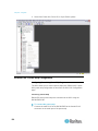
7. Press Enter. You are prompted to set the LAN interface speed.
18
Chapter 3: Installation and Configuration
8. By default, the LAN interface speed is set to Auto, which allows the
system to select the optimum speed. To keep the default, press Enter.
To set the speed to 10 or 100 Mbps, type the speed you want and
press Enter. You are prompted to select the duplex mode for the LAN
interface.
9. By default, the LAN interface duplex mode is set to Auto, which allows
the system to pick the optimum mode. Half duplex allows data to be
transmitted to and from the Dominion PX device, but not at the same
time. Full duplex allows data to be transmitted in both directions at the
same time.
To keep the default, press Enter. To specify half or full duplex, type
half or full and press Enter. You are prompted to confirm the
information you just entered.
10. All the configuration parameters have now been entered. All the
prompts are still displayed, so you can check the information you
entered. Do one of the following:
If the information is correct, type y and press Enter. The system
completes the configuration and displays a message when the
configuration is done.
If one or more parameters are not correct, type n and press Enter.
You are returned to the IP configuration prompt as shown in the
screenshot of Step 4, and given the opportunity to correct each
piece of information. When the information is correct, type y and
press Enter to complete the configuration and return to the
opening prompt.
If you want to terminate the configuration process, type c and
press Enter. The configuration is cancelled and you are returned
to the opening prompt.
19
Chapter 3: Installation and Configuration
11. If you entered y to confirm the configuration, a message appears
when the configuration is complete. You will be returned to the
opening prompt. You are now ready to begin using your Dominion PX.
Note: The IP address configured takes about 15 seconds to take
effect for the device connected via serial line, or even longer if
configured over DHCP.
Resetting to Factory Defaults
For security reasons, the Dominion PX device may be reset to factory
defaults only at the local serial console.
Important: Exercise caution before resetting Dominion PX to its
factory defaults. This erases any existing information and
customized settings, such as user profiles and threshold values.
To reset to factory defaults:
1. Connect a computer to the Dominion PX device over a serial
connection.
2. Launch a terminal emulation program such as HyperTerminal, Kermit,
or PuTTY, and open a window on the Dominion PX. Make sure serial
port settings use this configuration:
Baud rate (bits per second) = 9600
Data bits = 8
Stop bits = 1
Parity = None
Flow control = None
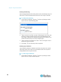
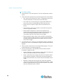
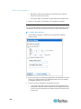
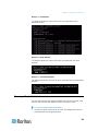
3. Press (and release) the Reset button of Dominion PX while pressing
the Esc key several times in rapid succession. A prompt (=>) should
appear after about one second.
4. Type defaults to reset the Dominion PX to its factory defaults.
20
Chapter 3: Installation and Configuration
The pictures show the location of the reset hole.
When resetting to factory defaults, do not use a DB9-to-USB adapter to
connect the Dominion PX serial cable to your PC. This may result in
misinterpreted characters at the special prompt. Connect the Dominion PX
serial cable to a PC with a DB9 serial port instead.
Note: HyperTerminal is available on Windows operating systems prior to
Windows Vista. For Windows Vista or later versions, you may use PuTTY,
which is a free program you can download from the Internet. See PuTTY's
documentation for details on configuration.
21
Chapter 4
Using Dominion PX
This chapter explains how to use Dominion PX. It describes the LEDs and
ports on the Dominion PX device, and explains how to use the LED display
panel. It also explains how the circuit breaker (overcurrent protector)
works and when the beeper sounds.
In This Chapter
Panel Components ..................................................................................22
Circuit Breaker.........................................................................................26
Beeper .....................................................................................................28
Measurement Accuracy...........................................................................28
Panel Components
Dominion PX comes in Zero U, 1U, and 2U sizes. All types of models
come with the following components on the outer panels.
•
Power cord
•
Outlets
•
Connection ports
•
LED display
•
Reset button
•
On 1U and 2U models, there is an additional component -- a blue
power LED.
Blue LED
Only 1U and 2U models have a blue power LED on the right side of the
front panel. This LED is lit solid as soon as the Dominion PX device is
powered on.
Power Cord
Most of Raritan PDUs come with an installed power cord, which is ready to
be plugged into an appropriate receptacle for receiving the input of
electricity. Such devices cannot be rewired by the user.
Connect each Dominion PX device to an appropriately rated branch circuit.
See the label or nameplate affixed to your Dominion PX device for
appropriate input ratings or range.
There is no power switch on the Dominion PX device. To power cycle the
PDU, unplug it from the branch circuit, wait 10 seconds and then plug it
back in.
22
Chapter 4: Using Dominion PX
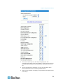
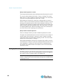
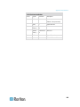
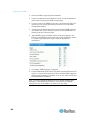
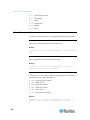
Outlets
The number of outlets varies from model to model. A small LED is
adjacent to each outlet to indicate the outlet or PDU state. The PDU is
shipped from the factory with all outlets turned ON. The table below
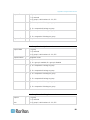
explains how to interpret different LED states.
LED state
Outlet status
What it means
Not lit (light grey)
Powered OFF
The outlet is not connected to power, or the control
circuitry's power supply is broken.
Red
ON and LIVE
LIVE power. The outlet is on and power is available.
Red flashing
ON and LIVE
The current flowing through the outlet is greater
than the upper warning (non-critical) threshold.
Green
OFF and LIVE
The outlet is turned off and power is available when
the outlet is turned on.
Green flashing
OFF and NOT LIVE
The outlet is turned off and power is not available
because the circuit breaker has tripped.
Yellow flashing
ON and NOT LIVE
The outlet is turned on but power is not available
because a circuit breaker has tripped.
The Dominion PX device has just been plugged in
and its management software is loading.
Cycling through Red,
Green and Yellow
n/a
-- OR -A firmware upgrade is being performed on the
device.
Note: When a Dominion PX device powers up, it proceeds with the
power-on self test and software loading for a few moments. At this time,
the outlet LEDs cycle through different colors. When the software has
completed loading, the outlet LEDs show a steady color and the LED
display illuminates.
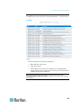
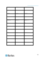
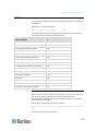
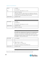
Connection Ports
The three ports, from left to right, are labeled as Serial (RJ-45), Feature
(RJ-12), and LAN (Ethernet, RJ-45). The table below explains what each
port is used for.
Port
Serial
Used for...
Establishing a serial connection between a computer and the Dominion PX
device:
Take the null-modem cable that was shipped with the Dominion PX device,
connect the end with the RJ-45 connector to the RS-232 serial port on the front
of the Dominion PX device, and connect the end with the DB9F connector to
23
Chapter 4: Using Dominion PX
Port
Used for...
the serial (COM) port on the computer.
The serial port is also used to interface with some Raritan access products
(such as the Dominion KX) through the use of a power CIM.
Feature
Connection to Raritan's environmental sensors.
LAN
Connecting the Dominion PX device to your company's network:
Connect a standard Cat5e/6 UTP cable to this port and connect the other end
to your network. This connection is necessary to administer the Dominion PX
remotely using the web interface.
There are two small LEDs adjacent to the port:
Green indicates a physical link and activity.
Yellow indicates communications at 10/100 BaseT speeds.
Note: Connecting any power CIM except for the D2CIM-PWR (such as
P2CIM-PWR) to the Dominion PX serial port causes all outlets to switch
ON state, even if they were previously OFF.
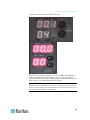
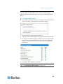
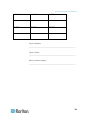
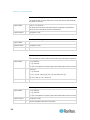
LED Display
The LED display is located on the side where the outlets are available. The
following picture shows the LED display.
The LED display consists of:
24
•
A row displaying three digits
•
A row displaying two digits
•
Up and Down buttons
Chapter 4: Using Dominion PX
Three-Digit Row
The three-digit row shows the power readings for the selected component.
Values that may appear include:
•
Current, voltage, or active power of the selected outlet
•
Current of the selected line or circuit breaker
•
The text “FuP,” which indicates that the firmware upgrade is being
performed
•
The text "CbE," which indicates the circuit breaker associated with the
selected outlet has been tripped
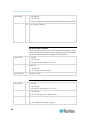
Two-Digit Row
The lower row shows the number of currently selected outlet, line or circuit
breaker. Values that may appear include:
•
Two-digit numbers: This indicates the selected outlet. For example, 03
indicates outlet 3.
•
Cx: This indicates the selected circuit breaker, where x is the circuit
breaker number. For example, C1 indicates Circuit Breaker 1.
•
n: This indicates the neutral line in a three-phase Y-wired model.
•
Lx: This indicates the selected line of a single-inlet PDU, where x is
the line number. For example, L2 indicates Line 2.
Note: For a single-phase model, L1 current represents the Unit
Current.
Automatic Mode
When left alone, the LED display cycles through the line readings and
circuit breaker readings, as available for your Dominion PX model. This is
the Automatic Mode.
Manual Mode
You can press the Up or Down button to enter the Manual Mode so that a
particular outlet, line or circuit breaker can be selected to show specific
readings.
To operate the LED display:
1. Press the Up or Down button until the desired outlet, line or circuit
breaker number is selected in the two-digit row.
Pressing the Up button moves up one selection.
Pressing the Down button moves down one selection.
25
Chapter 4: Using Dominion PX
2. Current of the selected component is shown in the three-digit row. It
appears in this format: XX.X (A).
3. If you select an outlet, you can press the Up and Down buttons
simultaneously to switch between the voltage, active power and
current readings.
The voltage appears in this format: XXX (V). It is displayed for
about five seconds, after which the current reading re-appears.
Active power appears in this format: X.XX (W). It is displayed for
about five seconds, after which the current reading re-appears.
Tip: A quick way to distinguish between voltage, current, and power is the
placement of the decimal point in the display. Voltage has no decimal point,
active power has a decimal point between the first and second digits, and
current has a decimal point between the second and third digits.
You can view current and voltage for the entire Dominion PX using the Up
and Down buttons to select outlet number 00.
Note: The LED display returns to the Automatic Mode after 10 seconds
elapse since the last time any button was pressed.
Reset Button
The reset button is located inside the small hole near the two-digit row.
The Dominion PX device can be reset to its factory default values using
this button when a serial connection is available. See Resetting to
Factory Defaults (on page 20).
Without the serial connection, pressing this reset button restarts the
device.
Circuit Breaker
Dominion PX models rated over 20 Amps (North American) or 16A
(international) contain branch circuit breakers with Type C Trip
Characteristic. These circuit breakers automatically trip (disconnect power)
when the current flowing through the circuit breaker exceeds its rating.
If the circuit breaker switches off power, the LED display shows:
•
CbE, which means "circuit breaker error," on the three-digit row.
•
The lowest outlet number affected by the circuit breaker error on the
two-digit row.
You are still able to switch between outlets on the LED display when the
circuit breaker error occurs. Outlets affected by the error show CbE.
Unaffected outlets show the current and voltage readings as described in
LED Display (on page 24).
26
Chapter 4: Using Dominion PX
Resetting the Button-Type Circuit Breaker
Your button-type circuit breakers may look slightly different from the
images shown in this section, but the reset procedure remains the same.
To reset the button-type breakers:
1. Locate the breaker whose ON button is up, indicating the breaker has
tripped.
2. Examine your Dominion PX device and the connected equipment to
remove or resolve the cause that results in the overload or short circuit.
This step is required, or you cannot proceed with the next step.
3. Press the ON button until it is completely down.
Resetting the Handle-Type Circuit Breaker
Your handle-type circuit breakers may look slightly different from the
images shown in this section, but the reset procedure remains the same.
To reset the handle-type breakers:
1. Lift the hinged cover over the breaker.
2. Check if the colorful rectangle or triangle below the operating handle is
GREEN, indicating the breaker has tripped.
27
Chapter 4: Using Dominion PX
3. Examine your Dominion PX device and the connected equipment to
remove or resolve the cause that results in the overload or short circuit.
This step is required, or you cannot proceed with the next step.
4. Pull up the operating handle until the colorful rectangle or triangle
becomes RED.
Beeper
The Dominion PX device includes a beeper to issue an audible alarm
when a critical situation occurs.
•
The beeper sounds an alarm within 3 seconds of a circuit breaker trip.
- OR -
•
The beeper sounds an alarm when the control board temperature
sensor exceeds 80 degrees Celsius (or 176 degrees Fahrenheit).
The beeper stops ringing after the critical situation disappears.
•
The beeper stops as soon as all circuit breakers have been reset.
- OR -
•
The beeper stops after the control board temperature sensor drops
below 70 degrees Celsius (or 158 degrees Fahrenheit).
Note: The temperature thresholds are factory defaults and can be
user-configurable.
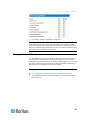
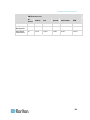
Measurement Accuracy
28
•
Voltage (per outlet): Range 0-255V, +/-5%, 3 digits, resolution 1V
•
Current (per outlet): Range 0-25A, +/-5%, 3 digits, resolution 0.1A
Chapter 5
Using the Web Interface
This chapter explains how to use the web interface to administer a
Dominion PX device.
In This Chapter
Logging in to the Web Interface ..............................................................29
Web Interface Elements ..........................................................................33
Using the Home Window .........................................................................38
Monitoring Line and Circuit Breaker Status.............................................41
Setting Up User Profiles ..........................................................................45
Setting Up User Groups ..........................................................................49
Access Security Control ..........................................................................54
Setting Up a Digital Certificate.................................................................65
Setting Up External User Authentication .................................................68
Setting Up Outlets and Power Thresholds ..............................................73
Environmental Sensors ...........................................................................80
Configuring and Using Alert Notifications................................................88
Setting Up Event Logging......................................................................100
Managing Dominion PX.........................................................................107
Outlet Grouping .....................................................................................125
Logging in to the Web Interface
To log in to the web interface, you must enter a user name and password.
The first time you log in, use the default user name (admin) and password
(raritan). You are then prompted to change the password for security
purposes.
After successfully logging in, you can create user profiles for your other
users. These profiles define their login names and passwords. See
Creating a User Profile (on page 45).
Login
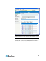
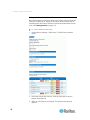
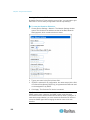
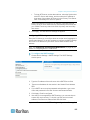
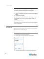
To log in to the web interface:
1. Open a browser, such as Microsoft Internet Explorer or Mozilla Firefox,
and type this URL:
http(s)://<ip address>
29
Chapter 5: Using the Web Interface
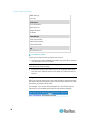
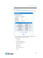
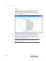
where <ip address> is the IP address of the Dominion PX device. The
Login page opens..
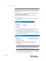
2. Type your user name and password in the Username and Password
fields.
Note: Both the user name and password are case sensitive, so make
sure you capitalize them correctly.
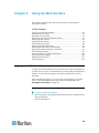
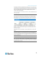
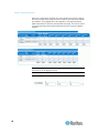
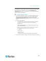
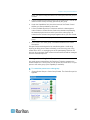
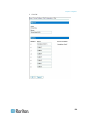
3. Click Login. The Home window opens.
30
Chapter 5: Using the Web Interface
Note: Depending on your model type and hardware configuration,
elements shown on your Home window may appear differently from this
image.
The web interface allows a maximum of 16 users to log in simultaneously.
You must enable Java script in the web browser for proper operation. If
Java Script is not enabled, features such as the Status Panel on the left
side of the interface does not display correctly.
31
Chapter 5: Using the Web Interface
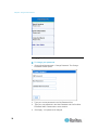
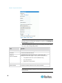
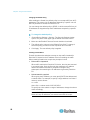
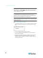
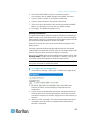
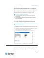
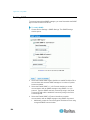
Changing Your Password
To change your password:
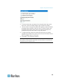
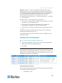
1. Choose User Management > Change Password. The Change
Password window opens.
2. Type your current password in the Old Password field.
3. Type your new password in the New Password and Confirm New
Password fields. Passwords are case sensitive.
4. Click Apply. Your password is changed.
32
Chapter 5: Using the Web Interface
Web Interface Elements
Every window in the web interface provides menus and a navigation path
across the top and a Status panel to the left.
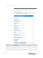
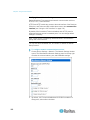
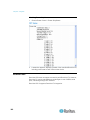
Menus
There are several menus in the web interface, each with their own set of
menu items:
Details
Outlet Details
Line Details
CB Details
PDU Details
Outlet Setup
Alerts
Alert Configuration
Alert Policies
Alert Policy Editor
Alert Destinations
User Management
Change Password
Users & Groups
User / Group System Permissions
User / Group Outlet Permissions
Device Settings
PDU Setup
Environmental Sensors
Network
Security
Certificate
Date / Time
Authentication
SMTP Settings
33
Chapter 5: Using the Web Interface
SNMP Settings
Event Log
Maintenance
Device Information
View Event Log
Update Firmware
Unit Reset
Outlet Groups
Outlet Group Details
Outlet Group Devices
Outlet Group Editor
Help
About Dominion PX
To select an option:
There are two ways to select an option from a menu:
•
Click the menu name to display a window listing each option, and then
click the option you want to select.
Note: The Home tab is not a menu. Clicking the Home tab takes you back
to the Dominion PX home page.
•
Position the cursor on the menu name. A list of options drops down
from the menu. Slide the cursor to the option you want and click it to
select it.
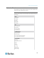
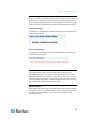
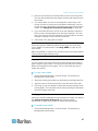
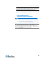
Navigation Path
When you select an option from a menu and navigate to a specific window,
the system displays a navigation path across the top that shows the menu
and option you selected to get there.
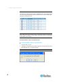
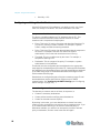
For example, if you choose User Management > User/Group System
Permissions, the navigation path looks like the following example.
34
Chapter 5: Using the Web Interface
To return to a previous window, click the window name in the navigation
path. Every navigation path begins at the Home window, so a single click
always takes you back to the Home window from anywhere in the interface.
You can click the Home tab from any page to take you back to the Home
window.
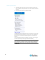
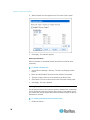
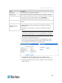
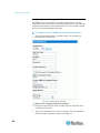
Status Panel
The Status panel appears on the left of every window in the interface. It
shows:
•
Present date and time.
•
Information about the user, including:
User name
User's present state (active, idle, and so on)
IP address of the user's computer
Date and time of the user's last login
•
Information about the Dominion PX device, including:
Model name and number
IP address
Firmware version
35
Chapter 5: Using the Web Interface
•
Information about all the users currently connected, including user
name, IP address, and present state. Your active session is included
in this list.
•
A link to the User Guide on the Raritan website.
The State field in the user information section considers a user to be "idle"
30 seconds after the last keyboard or mouse action. It then updates the
idle time every 10 seconds until another keyboard or mouse action is
detected.
If you exceed the idle time limit (by default, 15 minutes), you are logged
out and re-directed to the main login window automatically.
Important: Users still appear in the Connected Users list if they end
their session by closing their browser window without logging off.
Dominion PX removes their names when their sessions reach the
idle time limit.
36
Chapter 5: Using the Web Interface
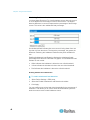
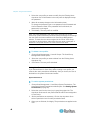
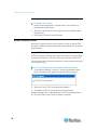
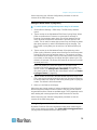
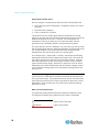
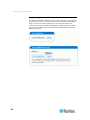
Status Messages
When you perform an operation from the Web interface, such as creating
a user profile or changing a network setting, a message appears at the top
of the window indicating whether or not the operation was successful. Be
sure to check this message to confirm that an operation was successful.
Successful messages
The following is an examples of a status message after an operation has
completed successfully:
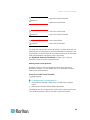
Unsuccessful messages
The following is an example of a status message after an operation has
completed unsuccessfully:
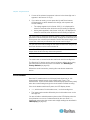
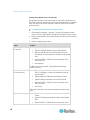
Unavailable Options
Sometimes certain actions are unavailable. When this occurs, the
appropriate buttons are non-functional, though different browsers may
display this differently. For example, if you select the Admin User Group in
Internet Explorer, the buttons for Copy, Modify, and Delete are grayed-out
since you cannot Copy, Modify, or Delete the Admin user group. In Firefox,
these buttons appear normal, but are unclickable.
Reset to Defaults
Many windows provide a Reset to Defaults button that returns all fields to
their default values. If you use this button, you must click the Apply button
afterward to save the defaults. If you do not, these fields retain the
non-default values.
37
Chapter 5: Using the Web Interface
Default Asterisk
If a field has an asterisk after it, as shown below,
then this field is currently set to its default value. If you change the default,
the asterisk disappears. If you reset it to the default, the asterisk returns.
Refresh
Many windows provide a Refresh button. If a window is open for a while,
the information displayed may become "stale." Click this button
periodically to reload the window and update the information displayed.
Using the Home Window
The Home window is the first window to appear after a successful login. It
consists of a Lines Status Display, Circuit Breaker Status, an Outlets list,
and an All Outlets Control panel. The home window also contains an
environmental sensors panel when environmental sensors are connected
to Dominion PX. The Home window refreshes every 30 seconds to keep
the data displayed up to date.
You can return to the Home window from any other window in the Web
interface by clicking:
•
The Home tab at the top of the interface
•
The Home link in the navigation path
•
The Raritan logo in the upper left of the window
•
The Device Model Name under the logo
Line Loads Display
The Line Loads display shows the current load on each of the Dominion
PX's current-carrying lines.
38
Chapter 5: Using the Web Interface
The status of each line is represented by a status bar. As the load on the
line increases, the colored portion grows to fill the bar. A status bar that is
nearly full indicates that the particular line is approaching its rated current
limit. The colored portion of the bar also changes colors as the load
crosses configured thresholds.
For more information on the status of each line, click the Details tab, then
select Line Detail.
Circuit Breaker Status
For Dominion PX models with circuit breakers, a circuit breaker status
display appears on the home page. This provides a quick view of each
circuit breaker's status and the current handled by each circuit breaker.
A status of Closed indicates that the circuit is closed and functioning
properly. A status of Open and a change in color indicates that a circuit
breaker has tripped.
For details on each circuit breaker, click the Details tab, then select CB
Detail.
Note: The most efficient use of Dominion PX occurs when current loads
are balanced between all circuit breakers. Using the Outlet Mapping on
the Device Details page, and the Circuit Breaker status on the Home Page,
you can arrange where devices are plugged into Dominion PX in order to
maintain that balance.
Note: The current drawn through a circuit breaker indicates the amount of
current flowing to a bank of outlets. In three-phase Dominion PX models,
this number does not match the current draw on each line since each bank
of outlets is tied to two lines.
39
Chapter 5: Using the Web Interface
Outlets List
The Outlets List displays each outlet on the Dominion PX device as a table
row with a view of the power status, the RMS current, and the RMS Power
through the individual outlet.
Note: RMS refers to Root Mean Square, a statistical method for measuring
certain types of variables. In this context, it gives the value of current that
is equivalent to a DC value.
Turning an Outlet On, Off, or Cycling the Power
To turn an outlet on, off, or cycle the power
1. Click On, Off, or Cycle.
2. A dialog for confirming the operation appears. Click OK and the outlet
switches ON, OFF, or cycles its power.
Tip: You can also turn an outlet on or off from the Outlet Details window.
40
Chapter 5: Using the Web Interface
Displaying Additional Details
To display additional details about an outlet, click the outlet name. This
displays the Outlet Details window. This window gives the name and
status of the outlet, as well as:
•
RMS Current
•
Power Factor
•
Maximum RMS Current
•
Voltage
•
Active Power
•
Apparent Power
Note: RMS refers to Root Mean Square, a statistical method for measuring
certain types of variables. In this context, it gives the value of current that
is equivalent to a DC value.
All Outlets Control
The All Outlets Control panel at the bottom of the Home Window allows
you to turn all outlets ON and OFF. Click On to turn all outlets ON, click Off
to turn all outlets OFF. As with individual outlets, you must confirm the
selection before it takes effect.
Note: Users must have permission to access all outlets in order to use All
Outlets Control.
Monitoring Line and Circuit Breaker Status
Dominion PX provides details for additional information on Line and Circuit
Breaker status.
41
Chapter 5: Using the Web Interface
Monitoring Unbalanced Loads
In a three-phase Dominion PX, a load imbalance occurs when the current
on a line differs from the average current of all three lines. The largest
absolute difference in current is expressed as a percentage of the average
current. This value is the unbalanced load percentage.
An unbalanced load indicates that more current is being drawn from one
line than it is from the others. The larger the percentage, the greater the
difference. Reducing this imbalance maximizes the power available for
use.
Enabling Unbalanced Load Detection displays the unbalanced loads
percentage below the three individual Line graphs. This Unbalanced Load
indicator is color coded:
•
White indicates the imbalance is below the non-critical threshold.
•
Yellow indicates the imbalance is above the non-critical threshold.
•
Red indicates the imbalance is above the critical threshold.
Enabling Unbalanced Load Detection
To enable unbalanced load detection:
1. Select Device Settings > PDU setup.
2. Select the Enable Unbalanced Load Detection checkbox.
3. Click Apply.
You can configure non-critical and critical thresholds for the percentage of
imbalance. This allows you to use the Alerts and Notification system as
another means to react to load imbalance events.
42
Chapter 5: Using the Web Interface
Configuring Unbalanced Load Thresholds
Configuring these thresholds determines when the Unbalanced Load
indicator changes colors from white to yellow to red. It also configures the
unbalanced load event thresholds used in Alert Notifications.
Unbalanced Load Detection must be enabled before these thresholds take
effect.
To configure unbalanced load thresholds:
1. Select Device Settings > PDU setup.
2. Set the Unbalanced Load percentage for the Upper Non-Critical
threshold and the Upper Critical threshold.
Warning: The difference between Critical and Non-Critical threshold
values must be at least 2 percent, and both threshold values cannot
exceed 100, so you must type a value below 99 for the Upper
Non-Critical threshold.
3. Click Apply.
Balancing Loads
Balancing the current draw on your lines maximizes the power usage
before a circuit breaker is tripped. To keep line loads as balanced as
possible, move servers and other equipment from over-utilized lines to
under-utilized ones.
In general this involves:
1. Checking what outlets receive power from the over-utilized line.
2. Unplugging a server from those outlets.
3. Plugging the server into an outlet receiving power from the
under-utilized line.
43
Chapter 5: Using the Web Interface
Line Details Page
To open the Line Details Page, choose Details > Line Details. The page
opens and displays for each line the present current draw, the largest
amount of current drawn since the Dominion PX device's last boot, and the
amount of available current that can be drawn.
The page also displays the amount of Voltage provided by each line.
Circuit Breaker Details Page
To view the Circuit Breaker details, click the Details tab, then select CB
Details.
44
Chapter 5: Using the Web Interface
Each bank of outlets governed by a circuit breaker is listed as a table, and
indicates what lines they draw power from. Each table contains the status
of the circuit breaker, present current draw through that bank, the largest
amount of current that was drawn by that bank since the Dominion PX
device last booted, and the amount of available current that the circuit
breaker can handle.
Setting Up User Profiles
Dominion PX is shipped with one built-in user profile: the admin profile,
which is used for the original login. This profile has full system and outlet
permissions, and should be reserved for the system administrator. This
profile cannot be modified or deleted.
All users must have a user profile. The profile specifies a login name and
password, and contains additional (optional) information about the user. It
also assigns the user to a User Group, and the User Group determines the
user's system and outlet permissions.
If you choose, you can refrain from assigning some or all users to a User
Group, and instead assign their system and outlets permissions on an
individual basis.
Note: By default, multiple users can log in at the same time using the login
name from the same profile. You can change this so only one user at a
time can use a specific login. This is done by choosing Device Settings >
Security and selecting the Enable Single Login Limitation checkbox.
Creating a User Profile
Creating new users adds a new login to Dominion PX. To create a new
user, you must have both the User/group Management privilege and an
IPMI Privilege level of OEM.
To create a user profile:
1. Choose User Management > Users & Groups. The User/Group
Management window opens, divided into a User Management panel
and a Group Management panel.
45
Chapter 5: Using the Web Interface
Note: Before entering any information in the user profile, make sure
the User Group is created and available for selection. See Setting Up
User Groups (on page 49).
2. In the User Management panel, type the following information about
the user in the corresponding fields:
Field
Type this...
New user name
The name the user enters to log in to the web interface.
Full Name
The user's first and last names.
Password,
The password the user enters to log in. Type it first in the
Password field and then again in the Confirm Password field.
Confirm Password
The password can be 4 to 32 characters long.
It is case sensitive.
Spaces are not permitted.
Email address
An email address where the user can be reached.
Mobile Number
A cell phone number where the user can be reached.
Note: New user name, Password, and Confirm Password are the only
required fields.
46
Chapter 5: Using the Web Interface
3. Select a User Group from the drop-down list in the User Group field.
The User Group determines the system functions and outlets this user
can access.
4. If you select None, the user is not assigned to a User Group. This
means you have to set the user's permissions individually. Until you
do this, the user is blocked from accessing any system functions and
outlets. See Setting User Permissions Individually (on page 48).
5. If you would like this user to set his or her own password, select the
Enforce user to change password on next login checkbox. The user
logs in the first time using the password you entered above, and then
is forced to change it to one of his or her choices.
6. Click Create. The user profile is created.
Note: The Use Password as Encryption Phrase, SNMP v3 Encryption
Phrase and Confirm SNMP Encryption Phrase apply only when using
secure SNMP v3 communication. See Using SNMP (on page 163) for
more details.
When using SNMP v3, both the user password and the encryption phrase
must be at least eight characters long.
Copying a User Profile
You can create a new user profile with the same settings as an existing
profile using the copy function. You can then modify the profile so that it
differs as necessary from the original. This is a quick and easy way to
create user profiles.
To copy a user profile:
1. Choose User Management > Users & Groups. The User/Group
Management window opens.
2. Select the existing user profile from the Existing Users drop-down list.
3. Type the name of the new user profile in the New User Name field.
4. Click Copy. A new user profile is created with the same settings as the
existing profile. The new profile can be seen by clicking the drop-down
list in the Existing Users field.
Modifying a User Profile
Users with User/Group Management permissions can modify user profiles.
See Setting the System Permissions (see "Setting System
Permissions" on page 50) for details on setting user permissions.
To modify a user profile:
1. Choose User Management > Users & Groups. The User/Group
Management window opens.
47
Chapter 5: Using the Web Interface
2. Select the user profile you want to modify from the Existing Users
drop-down list. All information in the user profile is displayed except
the password.
3. Make all necessary changes to the information shown.
To change the password, type a new password in the Password and
Confirm Password fields. If the password field is left blank, the
password is not changed.
4. Click Modify. The user profile is modified.
Note: The name displayed in the "User (not in a group)" list on the
User/Goup System Permissions window remains unchanged even though
the user name has been modified on the User/Group Management
window. To make the user name assigned to the "None" User Group
consistent on both windows, either leave the user name unchanged, or
delete the user profile and then re-create it with a new name.
Deleting a User Profile
To delete a user profile:
1. Choose User Management > Users & Groups. The User/Group
Management window opens.
2. Select the user profile you want to delete from the Existing Users
drop-down list.
3. Click Delete. The user profile is deleted.
Setting User Permissions Individually
If you selected None for User Group when creating a user profile, you
must set the user's permissions individually. Until you do this, the user is
blocked from all system functions and outlets.
System Permissions
To set the system permissions:
1. Choose User Management > User/Group System Permissions. The
User/Group System Permissions window opens. See Setting System
Permissions (on page 50).
2. Select the user from the User (not in group) drop-down list. The
drop-down list shows all user profiles that have NOT been assigned to
a User Group.
3. Set the permissions as necessary. Click on the drop-down list to
select a permission level for each permission listed.
4. When you are finished, click Apply. The permissions are applied to the
user.
48
Chapter 5: Using the Web Interface
Outlet Permissions
To set the outlet permissions:
1. Choose User Management > User/Group Outlet Permissions. The
User/Group Outlet Permissions window opens. See Setting Outlet
Permissions (on page 52).
2. Select the user from the User drop-down list.
3. Set the permissions as necessary. Click on the drop-down list to
select a permission level for each outlet.
4. When you are finished, click Apply. The permissions are applied to the
user.
Note: A minimum IPMI privilege level "user" is required to switch outlets
over IPMI, which causes no effect on web front-end use. However,
privilege level has no affect on outlet permissions.
Setting Up User Groups
Dominion PX is shipped with one User Group built in: the Admin User
Group. This User Group provides full system and outlet permissions. It can
be neither modified nor deleted.
When creating user profiles, the User Group field defaults to the Admin
User Group. This means that if you do not change the entry in this field, the
user has full system and outlet permissions. To restrict the user's
permissions, create a User Group with limited system and/or outlet
permissions, and assign the user to that group.
49
Chapter 5: Using the Web Interface
Creating a User Group
To create a User Group:
1. Choose User Management > Users & Groups. The User/Group
Management window opens. This window is divided into a User
Management panel and a Group Management panel.
2. In the Group Management panel, type the name of the group in the
New Group Name field.
3. Click Create. The User Group is created.
Setting System Permissions
System permissions include all major functional areas of the Web
interface. When you first create a User Group, all system permissions are
set to NO.
To set the system permissions for a User Group:
1. Choose User Management > Users/Group System Permissions. The
User/Group System Permissions window opens.
50
Chapter 5: Using the Web Interface
2. Select the User Group from the Group drop-down list. The
permissions that apply to this group appear. If this is the first time you
are setting the permissions for this group, all permissions are set to
No.
3. Set the permissions as necessary. Click on the drop-down list to
select a permission level for each permission listed.
4. When you are finished, click Apply. The permissions are applied to the
User Group.
51
Chapter 5: Using the Web Interface
Note: The "User (not in group)" field on this window is used to set
individual user permissions. If you are setting group permissions, you may
ignore this field.
Some permissions must be enabled with other permission for the effects
to apply. Check the individual task descriptions in this guide for details.
Setting Outlet Permissions
Setting outlet permissions allows you to specify which outlets the
members of a User Group are permitted to access. When you first create a
User Group, all outlet permissions are set to NO.
To set the outlet permissions for a User Group:
1. Choose User Management > Users/Group Outlet Permissions. The
User/Group Outlet Permissions window opens.
52
Chapter 5: Using the Web Interface
2. Select the User Group from the Group drop-down list. The
permissions that apply to this group appear. If this is the first time you
are setting the permissions for this group, all permissions are set to
No.
3. Set the permissions as necessary. Click on the drop-down list to
select a permission level for each outlet.
4. When you are finished, click Apply. The permissions are applied to the
User Group.
Note: The User field on this window is used to set individual user
permissions. If you are setting group permissions, you may ignore this
field.
Copying a User Group
You can create a new User Group with the same permissions as an
existing User Group using the copy function. You can then modify the
group so that its permissions differ as necessary from the original. This is a
quick and easy way to create User Groups.
To copy a User Group:
1. Choose User Management > Users & Groups. The User/Group
Management window opens.
2. Select the existing User Group from the Existing Groups drop-down
list.
3. Type the name of the new User Group in the New Group Name field.
4. Click Copy. A new User Group is created with the same permissions
as the existing group. The new User Group can be seen by clicking
the drop-down list in the Existing Groups field.
Modifying a User Group
The only attribute of a User Group that can be modified is the group name.
To modify a User Group name:
1. Choose User Management > Users & Groups. The User/Group
Management window opens.
2. Select the User Group you want to modify from the Existing Groups
drop-down list. The name appears in the New group name field.
3. Make any necessary changes to the name.
4. Click Modify. The User Group is modified.
Note: To modify a User Group's system or outlet permissions, repeat the
procedure for setting the system or outlet permissions described above
and make any necessary changes.
53
Chapter 5: Using the Web Interface
Deleting a User Group
To delete a User Group:
1. Choose User Management > Users & Groups. The User/Group
Management window opens.
2. Select the User Group you want to delete from the Existing Groups
drop-down list.
3. Click Delete. The User Group is deleted.
Access Security Control
Dominion PX provides tools to control access. You can require HTTPS
encryption, enable the internal firewall and create firewall rules, and create
login limitations.
Forcing HTTPS Encryption
HTTPS uses Secure Sockets Layer (SSL) technology to encrypt all traffic
to and from the Dominion PX so it is a more secure protocol than HTTP.
You can force users to access the Dominion PX web interface through the
HTTPS protocol only.
To force HTTPS access to the Dominion PX web interface:
1. Choose Device Settings > Security. The Security Settings window
opens. The panel at the upper left is labeled HTTP Encryption.
2. Select the Force HTTPS for web access checkbox.
3. Click Apply. HTTPS is now required for browser access.
Attempts using HTTP are redirected back to HTTPS automatically after
the "Force HTTPS for web access" checkbox is selected.
54
Chapter 5: Using the Web Interface
Configuring the Firewall
Dominion PX has a firewall that you can configure to prevent specific IP
addresses and ranges of IP addresses from accessing the Dominion PX
device. When Dominion PX was initially configured, you were prompted to
enable or disable IP access control. If you selected Disable (the default),
the firewall was not enabled.
To configure the firewall:
1. Enable the firewall.
2. Set the default policy.
3. Create rules specifying which addresses to accept and which ones to
drop.
Changes made to firewall rules take effect immediately. Any unauthorized
IP activities cease instantly.
Note: The purpose of disabling the firewall by default is to prevent users
from accidentally locking themselves out of the device. See Installation
and Configuration (on page 14).
Enabling the Firewall
The firewall rules, if any, take effect only after the IP firewall is enabled.
To enable the Dominion PX firewall:
1. Choose Device Settings > Security. The Security Settings window
opens. Locate the panel labeled IP Access Control.
2. Select the Enable IP Access Control checkbox. This enables the
firewall.
3. Click Apply. The firewall is enabled.
55
Chapter 5: Using the Web Interface
Changing the Default Policy
After enabling the firewall, the default policy is to accept traffic from all IP
addresses. This means only IP addresses dropped by a specific rule will
NOT be permitted to access the Dominion PX.
You can change the default policy to DROP, in which case traffic from all
IP addresses is dropped except the IP addresses accepted by a specific
rule.
To change the default policy:
1. Choose Device Settings > Security. The Security Settings window
opens. The panel at the upper right is labeled IP Access Control.
2. Make sure the Enable IP Access Control checkbox is selected.
3. The default policy is shown in the Default Policy field. To change it,
select the policy you want from the drop-down list in the field.
4. Click Apply. The new default policy is applied.
Creating Firewall Rules
Firewall rules determine whether to accept or drop traffic intended for
Dominion PX, based on the IP address of the host sending the traffic.
When creating firewall rules, keep these principles in mind:
•
Rule order is important.
When traffic reaches the Dominion PX device, the rules are executed
in numerical order. Only the first rule that matches the IP address
determines whether the traffic is accepted or dropped. Any
subsequent rules matching the IP address are ignored by Dominion
PX.
•
Subnet mask is required.
When typing the IP address, you must specify BOTH the address and
a subnet mask. For example, to specify a single address in a Class C
network, use this format:
x.x.x.x/24
where /24 = a subnet mask of 255.255.255.0.
To specify an entire subnet or range of addresses, change the subnet
mask accordingly.
Note: Valid IP addresses range from 0.0.0.0 through 255.255.255.255.
Make sure any IP addresses you entered are within the scope.
56
Chapter 5: Using the Web Interface
To create firewall rules:
1. Choose Device Settings > Security. The Security Settings window
opens. The panel at the upper right is labeled IP Access Control.
2. Make sure the Enable IP Access Control checkbox is selected.
3. Create specific rules. The following explains how to:
Action
Add a rule to the end of
the rules list
Do this...
Type an IP address and subnet mask in the IP/Mask field.
Select ACCEPT or DROP from the drop-down list in the Policy field.
Click Append.
Do NOT enter a rule number. The system automatically numbers the rule.
Insert a rule between two
existing rules
Type a rule number where you want to insert a new rule above in the
Rule # field. For example, to insert a rule between rules #5 and #6, type
6.
Type an IP address and subnet mask in the IP/Mask field.
Select ACCEPT or DROP from the drop-down list in the Policy field.
Click Insert.
The system inserts the rule and automatically renumbers the rules.
Replace an existing rule
Type the number of the rule to be replaced in the Rule # field.
Type an IP address and subnet mask in the IP/Mask field.
Select ACCEPT or DROP from the drop-down list in the Policy field.
Click Replace.
This system replaces the existing rule with the one you just created.
57
Chapter 5: Using the Web Interface
4. When finished, the rules appear in the IP Access Control panel.
5. Click Apply. The rules are applied.
Deleting Firewall Rules
Remove obsolete or unneeded firewall rules from the rules list when
necessary.
To delete a firewall rule:
1. Choose Device Settings > Security. The Security Settings window
opens.
2. Make sure the Enable IP Access Control checkbox is selected.
3. Type the number of the rule to be deleted in the Rule # field.
4. Click Delete. The rule is removed from the IP Access Control panel.
5. Click Apply. The rule is deleted.
Creating Group Based Access Control Rules
Group based access control rules are similar to firewall rules, except they
can be applied to members of specific User Groups. This enables you to
give entire User Groups system and outlet permissions, based on their IP
addresses or subnets.
To create group based access control rules:
1. Enable the feature.
58
Chapter 5: Using the Web Interface
2. Set the default action.
3. Create rules that accept or drop traffic sending from specific
addresses when they are associated with a specific User Group.
Changes made do not affect users currently logged in until the next login.
Enabling the Feature
You must enable this access control feature before any relevant rule can
take effect.
To enable group based access control rules:
1. Choose Device Settings > Security. The Security Settings window
opens. Go to the panel labeled Group based System Access Control.
2. Select the Enable Group based System Access Control checkbox.
This enables the feature.
3. Click Apply. Group based access control rules are enabled.
Changing the Default Action
The default action is shown in the Group based System Access Control
panel on the Security Settings window.
To change the default action:
1. Choose Device Settings > Security. The Security Settings window
opens. Go to the panel labeled Group based System Access Control.
2. Make sure the Enable Group based System Access Control checkbox
is selected.
3. Select the action you want from the Default Action drop-down list.
4. Click Apply. The default action is applied.
59
Chapter 5: Using the Web Interface
Creating Group Based Access Control Rules
Group based access control rules accept or drop traffic intended for the
Dominion PX device, based on the user's group membership. Like firewall
rules, the order of the rule is important, since the rules are executed in
numerical order.
To create group based access control rules:
1. Choose Device Settings > Security. The Security Settings window
opens. Go to the panel labeled Group based System Access Control.
2. Make sure the Enable Group based System Access Control checkbox
is selected.
3. Create or delete specific rules:
Action
Do this...
Add a rule to the end of
Type a starting IP address in the Starting IP field.
the rules list
Type an ending IP address in the Ending IP field.
Select a User Group from the drop-down list in the
Group field. This rule applies to members of this group
only.
Select ACCEPT or DROP from the drop-down list in
the Policy field.
Click Append.
Do NOT enter a rule number. This system automatically
numbers the rule.
Insert a rule between
two existing rules
Type the higher of the two rule numbers in the Rule #
field. For example, to insert a rule between rules #5
and #6, type 5.
Type a starting IP address in the Starting IP field.
Type an ending IP address in the Ending IP field.
Select ACCEPT or DROP from the drop-down list in
the Action field.
Click Insert.
The system inserts the rule and automatically renumbers the
rules.
Replace an existing rule
60
Type the number of the rule to be replaced in the Rule
# field.
Type an IP address and subnet mask in the IP/Mask
field.
Select ACCEPT or DROP from the drop-down list in
Chapter 5: Using the Web Interface
Action
Do this...
the Action field.
Click Replace.
This system replaces the existing rule with the one you just
created.
4. When you are finished, click Apply. The rules are applied.
Deleting Group Based Access Control Rules
When any access control rule becomes unnecessary or obsolete, you
should remove it.
To delete a group based access control rule:
1. Choose Device Settings > Security. The Security Settings window
opens.
2. Make sure the Enable Group based System Access Control checkbox
is selected.
3. Type the number of the rule to be deleted in the Rule # field.
4. Click Delete. The rule is removed from the Group based System
Access Control panel.
5. Click Apply. The rule is deleted.
Setting Up User Login Controls
You can set up login controls to make it more difficult for hackers to access
Dominion PX and the devices connected to it. You can arrange to lock
persons out after a specified number of failed logins, limit the number of
persons who can log in at the same time using the same login, and force
users to create strong passwords.
61
Chapter 5: Using the Web Interface
Enabling User Blocking
User blocking determines how many times a user can attempt to log in to
Dominion PX and fail authentication before the user's login is blocked.
To enable user blocking:
1. Choose Device Settings > Security. The Security Settings window
opens. Go to the User Blocking panel.
2. Type a number in the "Max. number of failed logins" field. This is the
maximum number of failed logins the user is permitted before the
user's login is blocked from accessing the Dominion PX device. If no
number is entered, there is no limit on failed logins.
3. Type a number in the "Block time" field. This is the length of time in
minutes the login is blocked.
4. Click Apply. The user blocking limits are applied.
Enabling Login Limitations
Login limitations determine whether more than one person can use the
same login name at the same time, and whether users are required to
change passwords at regular intervals.
To enable login limitations:
1. Choose Device Settings > Security. The Security Settings window
opens. Go to the Login Limitations panel.
62
Chapter 5: Using the Web Interface
2. To prevent more than one person from using the same login at the
same time, select the Enable Single Login Limitation checkbox.
3. To force users to change their passwords regularly, select the Enable
Password Aging checkbox, and then enter a number of days in the
Password Aging Interval field. Users are required to change their
password every time that number of days has passed.
4. To adjust how long users can remain idle before they are forcibly
logged out by Dominion PX, enter a time in minutes in the Idle Timeout
field. The default value is 15 minutes.
5. Click Apply. The controls are applied.
Tip: Keep the idle timeout to 15 minutes or less if possible. This reduces
the number of idle sessions connected, and the number of simultaneous
commands sent to Dominion PX.
63
Chapter 5: Using the Web Interface
Enabling Strong Passwords
Use of strong passwords makes it more difficult for intruders to crack user
passwords and access the Dominion PX device. By default, strong
passwords should be at least eight characters long and contain upper- and
lower-case letters, numbers, and special characters, such as @ or &.
To force users to create strong passwords:
1. Choose Device Settings > Security. The Security Settings window
opens. The Strong Passwords panel appears at the bottom of the
window.
2. Select the Enable Strong Passwords checkbox to activate the strong
password feature. The following are the default settings:
Minimum length
= 8 characters
Maximum length
= 16 characters
At least one lowercase character
= Required
At least one uppercase character
= Required
At least one numeric character
= Required
At least one printable special character
= Required
Number of restricted passwords
=5
Note: The maximum password length accepted by Dominion PX is 32
characters.
64
Chapter 5: Using the Web Interface
3. Make any necessary changes to the default settings.
4. When you are finished, click Apply. The changes are applied.
Setting Up a Digital Certificate
Having an X.509 digital certificate ensures that both parties in an SSL
connection are who they say they are. To obtain an SSL certificate for
Dominion PX, create a Certificate Signing Request (CSR) and submit it to
a certificate authority (CA).
After the CA processes the information in the CSR, it provides you with a
certificate, which you must install on the Dominion PX device.
Note: See Forcing HTTPS Encryption (on page 54) for instructions on
forcing users to employ SSL when connecting to Dominion PX.
65
Chapter 5: Using the Web Interface
Creating a Certificate Signing Request
Follow this procedure to create the CSR for your Dominion PX device.
To create a CSR:
1. Choose Device Setting > Certificate. The first page of the SSL Server
Certificate Management window appears.
2. Provide the information requested.
66
Field
Common name
Type this...
The fully qualified domain name (FQDN) of your Dominion PX device.
Organizational unit
The name of your department.
Organization
The registered name of your company.
Chapter 5: Using the Web Interface
Field
Locality/City
Type this...
The city where your company is located.
State/Province
The full name of the state or province where your company is located.
Country (ISO code)
The country where your company is located. Use the standard ISO
country code. For a list of ISO codes, visit the ISO website
(http://www.iso.org/iso/country_codes/iso_3166_code_lists.htm).
Email
An email address where you or another administrative user can be
reached.
Challenge Password
The password used to protect the private key. Type it first in the
Challenge Password field and then again in the Confirm Challenge
password field.
Confirm Challenge
Password
The password is case sensitive, so ensure you capitalize the letters
correctly.
Note: All fields are mandatory, including the Organizational Unit,
Locality/City and State/Province fields. If you generate a CSR without
values in the required fields, you cannot obtain third party certificates.
3. Select the key length (bits) from the drop-down list in this field. Default
is 1024, but you can also select 2048.
4. Click Create. The CSR is created and the second page of the SSL
Server Certificate Management window opens. This window shows
the information you entered when creating the CSR.
5. To download the newly-created CSR to your computer, click
Download. You are prompted to open or save the file, named csr.txt.
6. After the file is stored on your computer, submit it to a CA to obtain the
digital certificate.
67
Chapter 5: Using the Web Interface
Installing a Certificate
After the CA provides a signed certificate according to the CSR you
submitted, you must install it on the Dominion PX device.
To install the certificate:
1. Choose Device Settings > Certificate. The second page of the Server
Certificate Management window opens.
2. Type the path and name of the certificate file in the SSL Certificate File
field, or click Browse and select the file.
3. Click Upload. The certificate is installed on the Dominion PX device.
Setting Up External User Authentication
For security purposes, users attempting to log in to Dominion PX must be
authenticated. Dominion PX supports the access using one of these
authentication mechanisms:
•
Local database of user profiles in the Dominion PX device
•
Lightweight Directory Access Protocol (LDAP)
•
Remote Access Dial-In User Service (RADIUS) protocol
By default, Dominion PX is configured for local authentication. If you stay
with this method, you do not need to do anything other than create user
profiles for each authorized user. If you prefer to use an external LDAP or
RADIUS server, you must:
•
Provide Dominion PX with the information about the server.
•
Create user profiles for users who are authenticated externally
because a user profile determines the User Group to which the user
belongs, and determines the system and outlet permissions for the
user accordingly.
When users log in with External Authentication, they cannot perform
operations on Outlet Groups. Users must authenticate locally to do this.
Note: Setting the LDAP user attribute rciusergroup to admin allows an
Active Directory user to log in to Dominion PX with Administrator privileges.
This occurs even if the user is assigned to the Unknown user group that
normally has no access permissions.
When configured for LDAP authentication, all Dominion PX users must
have an account on the LDAP server. Local-authentication-only users will
no longer have access to Dominion PX except for the admin, who always
have access to Dominion PX.
68
Chapter 5: Using the Web Interface
Gathering Information for LDAP Configuration
It requires knowledge of your LDAP server and directory settings to
configure Dominion PX for LDAP authentication. If you are not familliar
with the settings, consult your LDAP administrator for help.
To configure LDAP authentication, you need to check:
•
The IP Address or hostname of the LDAP server
•
The IP address of a backup or secondary LDAP server (optional)
•
Whether the Secure LDAP protocol (LDAP over SSL) is being used
- If Secure LDAP is in use, consult your LDAP administrator for the CA
certificate file.
•
The network port used by the LDAP server
•
The type of LDAP server used, usually one of the following options:
- A generic LDAP server
- Novell Directory Service
- Microsoft Active Directory (AD)
If using a Microsoft Active Directory server, consult your AD
administrator for the name of the Active Directory Domain.
•
The Base DN of the server (used for searching for users)
•
The login name attribute (or AuthorizationString)
•
The user entry object class
•
The user search subfilter (or BaseSearch)
69
Chapter 5: Using the Web Interface
Setting Up LDAP Authentication
To set up LDAP authentication:
1. Choose Device Settings > Authentication. The AuthenSettings
window opens. The LDAP parameters appear on the left side of the
window.
2. Select the LDAP radio button to enable the LDAP section of the page.
3. User LDAP Server - Type the IP address or DNS name of your
LDAP/LDAPS remote authentication server (up to 37 characters).
When the Enable Secure LDAP option is selected, the DNS name
must be used.
70
Chapter 5: Using the Web Interface
4. Backup User LDAP Server - Type the IP address or DNS name of
your backup LDAP/LDAPS server (up to 37 characters). When the
Enable Secure LDAP option is selected, the DNS name must be used.
Note that the remaining fields share the same settings with the
Primary LDAP Server field. Optional
5. SSL Enabled - Select this checkbox if you would like to use SSL.
Secure Sockets Layer (SSL) is a cryptographic protocol that allows
Dominion PX to communicate securely with the LDAP/LDAPS server.
6. Port - The default Port is 389. Either use the standard LDAP TCP port
or specify another port.
7. SSL Port - The default is 636. Either use the default port or specify
another port. This field is enabled when the Enable Secure LDAP
checkbox is selected.
8. Certificate File - Consult your authentication server administrator to
get the CA certificate file in Base64 encoded X-509 format for the
LDAP/LDAPS server. Use the Browse button to navigate to the
certificate file. This field is enabled when the Enable Secure LDAP
option is selected.
9. Base DN of user LDAP server - Enter the name you want to bind
against the LDAP/LDAPS (up to 31 characters), and where in the
database to begin searching for the specified Base DN. An example
Base Search value might be: cn=Users,dc=raritan,dc=com.
Consult your authentication server administrator for the appropriate
values to enter into these fields.
10. Type of external LDAP/LDAPS server. Choose from among the
options available:
Generic LDAP Server.
Novell Directory
Microsoft Active Directory. Active Directory is an implementation
of LDAP/LDAPS directory services by Microsoft for use in
Windows environments.
11. Type the following information in the corresponding fields. LDAP
needs this information to verify user names and passwords.
Login name attribute (also called AuthorizationString)
User entry object class
User search subfilter (also called BaseSearch)
12. Active Directory Domain - Type the name of the Active Directory
Domain. For example, testradius.com. Consult with your Active
Directive Administrator for a specific domain name.
13. Click Apply. LDAP authentication is now in place.
71
Chapter 5: Using the Web Interface
Note: If the Dominion PX clock and the LDAP server clock are out of sync,
the certificates are considered expired and users are unable to
authenticate using LDAP. To ensure proper synchronization,
administrators should configure Dominion PX and the LDAP server to use
the same NTP server.
Setting Up RADIUS Authentication
To set up RADIUS authentication:
1. Choose Device Settings > Authentication. The Authentication Settings
window opens. The RADIUS parameters appear on the right side of
the window.
2. Click the RADIUS radio button.
3. Type the IP address of the RADIUS server in the Server field.
4. Type the shared secret in Shared Secret field. The shared secret is
necessary to protect communication with the RADIUS server.
5. By default, Dominion PX uses the standard RADIUS port 1812
(authentication) and 1813 (accounting). If you prefer to use
non-standard ports, change the ports.
6. Type the timeout period in seconds in the Timeout field. This sets the
maximum amount of time to establish contact with the RADIUS server
before timing out. Default is 1 second.
7. Type the number of retries permitted in the Retries field. Default is 3.
8. If you have additional RADIUS servers, click More Entries. Fields for
four additional servers appear. Enter the same information in Steps
2-7 for each additional server.
9. Select an authentication protocol from the drop-down list in the Global
Authentication Type field. Your choices include:
72
PAP (Password Authentication Protocol)
CHAP (Challenge Handshake Authentication Protocol)
Chapter 5: Using the Web Interface
CHAP is generally considered more secure because the user name
and password are encrypted, while in PAP they are transmitted in the
clear.
10. Click Apply. RADIUS authentication is now in place.
Setting Up Outlets and Power Thresholds
Dominion PX is shipped with certain Dominion PX and outlet power
thresholds already defined. You can change the default Dominion PX
thresholds, and you can give each outlet a name and change its default
thresholds.
When setting the thresholds, remember that you can set up alerts that are
triggered whenever any of these thresholds are crossed. See
Configuring and Using Alert Notifications (on page 88).
73
Chapter 5: Using the Web Interface
Setting the Global Default Outlet State
Set a global default for the power state of the outlets when the Dominion
PX device is powered on. Setting an individual outlet's startup state to
something other than Device Default overrides this default state for that
outlet. See Naming Outlets (on page 77).
To set the default outlet state:
1. Choose Device Settings > PDU Setup. The PDU Setup window
opens.
2. Select the default state from the "Default outlet state on device
startup" drop-down list.
3. When you are finished, click Apply. The default state setting is
applied.
74
Chapter 5: Using the Web Interface
Users require the Unit & Outlet Configuration permission to see the
contents of the PDU Setup page.
Setting the Global Power Cycling Delay
To set the power cycling and sequence delay for all outlets:
1. Choose Device Settings > PDU Setup. The PDU Setup window
opens.
2. Type a number in the field labeled PDU Power Cycling Delay. When
power to the Dominion PX device is cycled (either manually or
because of a temporary power loss), this number determines how
many seconds Dominion PX waits before it provides power to the
outlets. This is useful in cases where power may not initially be stable
after being restored, or when UPS batteries may be charging. The
PDU Power Cycling Delay can be set from 0 to 3600 seconds (one
hour).
3. Type a number in the field labeled Power off period during outlet
power cycling. When the outlets on the Dominion PX device are power
cycled, they are turned off and then back on. The number you enter
here determines the length of time (in seconds) it takes for the outlets
to turn back on after they are shut down during the power cycle. The
default is 10 seconds. The Power Off Period can be set from 0 to 3600
seconds (one hour).
Note: The number you enter here applies to all outlets on the
Dominion PX device. However, you can override this number for
specific outlets (see Setting Outlet Thresholds (on page 78)). You
can power cycle an outlet from the Outlet Details window (see Power
Cycling an Outlet (on page 80)).
4. Type a number of seconds in the field labeled Sequence Delay in ms.
The outlet sequence delay determines the time interval the Dominion
PX device takes from outlet to outlet when powering ON or cycling all
outlets. The default is 200 milliseconds.
5. When you are finished, click Apply.
When there are a large number of outlets, set both the Power off period
and the Sequence Delays to lower numbers. This way you can avoid a
long wait before all the outlets are available again. This is especially useful
when dealing with outlets grouped from other Dominion PX devices.
Users require the Unit & Outlet Configuration permission to see the
contents of the PDU Setup page.
Setting the Hysteresis for Outlet Thresholds
By default, Dominion PX uses a Hysteresis setting when measuring the
outlet current against thresholds. See A Note About Untriggered Alerts
(on page 98) to understand how this setting works.
75
Chapter 5: Using the Web Interface
Setting PDU Thresholds
Users require the Unit & Outlet Configuration permission to see the
contents of the PDU Setup page. Both the Unit & Outlet Configuration and
the Line & Circuit Configuration permissions are required to adjust
thresholds on the page.
To set the Dominion PX thresholds:
1. Choose Device Settings > PDU Setup. The PDU Setup window
opens.
2. Set the voltage, current, temperature, and (if applicable) circuit
breaker current thresholds for the device in the Thresholds panel.
Enter critical or non-critical threshold for each setting.
3. When you are finished, click Apply.
Setting the Outlet Power-On Sequence
By default, the outlets are sequentially powered on in the ascending order
from outlet 1 to the final outlet when turning ON or power cycling all outlets
on the Dominion PX device. You can change the order in which the outlets
power ON. This is useful when the connected IT equipment has multiple
power supplies that should be powered up together.
To set the outlet power-on sequence:
1. Choose Device Settings > PDU Setup. The PDU Setup window
opens.
2. The current outlet power-on sequence appears in the list under Outlet
Sequencing. To change the priority of an outlet, select it from the list
and click one of the following buttons.
76
First: Moves the outlet to the top of the list, making it the first outlet
to receive power.
Up: Moves the outlet up one position in the list.
Chapter 5: Using the Web Interface
Down: Moves the outlet down one position in the list.
Last: Moves the outlet to the bottom of the list, making it the last
outlet to receive power.
3. Click Apply. The new sequence is saved.
Note: If you use Outlet Grouping to group outlets together, you should
adjust the Outlet Sequencing to ensure that all outlets from this Dominion
PX that are part of the same group, power up consecutively.
Naming Outlets
You can give each outlet a name to help you identify the IT equipment
connected to it.
To name outlets:
1. Choose Details > Outlet Setup. The Outlet Setup window opens.
2. Select the outlet from the "Show setup of outlet" drop-down list.
77
Chapter 5: Using the Web Interface
3. Type a name for the outlet in the Outlet Name field. It is a good idea to
give the outlet an easily recognizable name that helps you identify the
device connected to it. You can always change names if the device is
replaced.
4. Select an outlet state from the drop-down list in the "Outlet state on
device startup" field. This determines if the outlet is ON or OFF when
the Dominion PX device powers up. If set to Device Default, the state
for this outlet is determined by the Default Outlet State in the PDU
Setup page.
5. Click Apply. The new name is applied.
Setting Outlet Thresholds
To set the current thresholds of an outlet:
1. Choose Details > Outlet Setup. The Outlet Setup window opens.
2. Select an outlet from the "Show setup of outlet" drop-down list.
3. Type a number in the field labeled Power off period during outlet
power cycling. When an outlet is power cycled, it is turned off and then
back on. The number you enter here determines the length of time (in
seconds) it takes for the outlet to turn back on after it is shut down
during the power cycle. If left blank, this outlet uses the value set in the
PDU Setup page as a default.
Note: You can power cycle an outlet from the Outlet Details window.
See Power Cycling an Outlet (on page 80).
4. Set the RMS current thresholds for the outlet in the Thresholds panel.
Ensure the value you enter for the upper critical threshold is NOT
larger than the maximum current rating of the outlet.
5. When you are finished, click Apply. The setup details are applied.
Note: For any outlet whose current rating is 10A, the difference of default
lower non-critical and lower critical thresholds is less than 1 Amp after both
values are encoded and then decoded. When this occurs, change either
default value to make the difference equal to or larger than 1 Amp.
78
Chapter 5: Using the Web Interface
Viewing Outlet Details
To display details about a particular outlet:
1. Choose Details > Outlet Details. The Outlet Details window opens.
2. Select an outlet from the "Show details of outlet" drop-down list. The
window shows these details about the outlet:
Outlet name
Outlet status
Line Pair (if applicable)
Circuit Breaker (if applicable)
Readings, including:
RMS current
Power Factor
Maximum RMS Current
Voltage
79
Chapter 5: Using the Web Interface
Active Power
Apparent Power
Active Energy (energy consumption, if applicable)
Note: To display the Outlet Setup window, click the Setup link. See
Naming Outlets (on page 77) for a picture of the Outlet Setup
Window.
Power Cycling an Outlet
Power Cycling an Outlet turns an outlet OFF, then ON again. This works
only for outlets that are in the ON state.
To power cycle an outlet:
1. Choose Details > Outlet Details. The Outlet Details window opens.
2. Select an outlet from the "Show details of outlet" drop-down list. The
outlet must be ON.
3. Click Cycle.
Note: You can also power cycle an outlet from the Home window.
The length of time between the off and on states in a power cycle can
be set on the Dominion PX device as a whole, and for individual
outlets. See Setting PDU Thresholds (on page 76) and Setting
Outlet Thresholds (on page 78).
Turning an Outlet On or Off
To turn an outlet on or off:
1. Choose Details > Outlet Details. The Outlet Details window opens.
2. Select an outlet from the "Show details of outlet" drop-down list.
3. Click On to turn the outlet ON. Click Off to turn the outlet OFF.
Note: You can also turn an outlet on or off from the Home window.
Environmental Sensors
Dominion PX can monitor the environmental conditions where external
sensors are placed, such as temperature and humidity in the surrounding
environment.
To add environmental sensors:
1. Physically connect the environmental sensors to the Dominion PX
device. See Connecting Environmental Sensors (on page 81).
80
Chapter 5: Using the Web Interface
2. Configure the sensors in the Dominion PX web interface.
a. Map the physical sensor to a logical sensor entry.
b. Configure thresholds for that sensor entry.
c.
Describe the sensor's physical location in the rack or server room.
Connecting Environmental Sensors
To enable Dominion PX to measure environmental factors, connect one or
multiple environmental sensors to the Dominion PX device. For
connecting a number of environmental sensors, Raritan's sensor hubs are
required.
To directly connect an environmental sensor:
•
Connect the cable of the environmental sensor to the Feature port on
the Dominion PX device.
To connect environmental sensors via the sensor hubs:
1. Connect a sensor hub to the Dominion PX device.
a. Plug one end of the Raritan-provided phone cable (4-wire, 6-pin)
into the IN port (Port 1) of the hub.
b. Plug the other end into the Feature port of the Dominion PX
device.
2. Connect environmental sensors to any of the four OUT ports on the
hub.
3. If necessary, you can cascade sensor hubs to connect more
environmental sensors.
a. Connect a second sensor hub to the first sensor hub:
Plug one end of the Raritan-provided phone cable to the IN
port of the second sensor hub.
Plug the other end of the cable to one of the OUT ports of the
first sensor hub.
b. Repeat cascading sensor hubs as desired.
c.
Connect environmental sensors to any of available OUT ports on
these cascaded hubs.
81
Chapter 5: Using the Web Interface
This diagram illustrates a configuration with cascaded sensor hubs
connected.
Dominion PX device
Raritan-provided phone cable
Sensor hub
Environmental sensors
Note: The dual temperature and humidity sensors are compatible with
both DPX and DPC models of Dominion PX.
82
Chapter 5: Using the Web Interface
Mapping Environmental Sensors
After environmental sensors are physically connected to the Dominion PX
device, they must be mapped to its logical sensors before Dominion PX
recognizes the readings from them.
To map environmental sensors:
1. Choose Device Settings > Environmental Sensors. The
Environmental Sensors window opens. The page lists the logical
Temperature and Humidity sensors first.
2. When physical sensors are attached to Dominion PX, they appear
listed below the logical sensors. Temperature sensors are listed in the
Environmental Temperature Sensors table, humidity sensors in the
Environmental Humidity Sensors table. If the sensors are not attached
properly, the message appears: No sensors were detected.
3. For each physical sensor (shown as a row) in the table, click a radio
button under the logical sensor (shown as columns) you want to map it
to. Dominion PX now tracks this sensor's readings and display it on
the home page when configuration is finished.
If you do not want to track the readings of a particular sensor, leave
that row blank.
83
Chapter 5: Using the Web Interface
4. To unmap a logical sensor from any physical sensor, click clear at the
bottom of the column. That logical sensor are no longer associated
with any of the physical sensors.
Note: It is possible (but not advisable) to map more than one logical sensor
to a single physical sensor. You cannot map multiple physical sensors to a
single logical one.
Identifying Environmental Sensors for Mapping
Each sensor includes a serial number tag on the sensor cable.
The serial number for each sensor also appears listed with each physical
sensor detected by Dominion PX.
Match the serial number from the tag to the ones in the Environmental
Sensor table in order to identify any different sensors, then map the
physical sensor to the logical sensors and configure the thresholds
appropriately.
84
Chapter 5: Using the Web Interface
Configuring Environmental Sensors and Thresholds
To make sensors more useful, rename the logical sensors that are in use
and configure their threshold settings. Configuring thresholds for these
sensors allows Dominion PX to generate an alert whenever environmental
conditions detected by those sensors move outside of your ideal values.
To configure environmental sensors in the web interface:
1. From the Environmental Sensors page, locate the logical sensors that
have been mapped to physical sensors as previously described.
2. In the Name field, type a new name for each mapped sensor that help
you identify the sensor and its purpose.
Note: Do NOT leave any Name field blank because sensor names are
required for successfully saving sensor configurations.
3. Configure the upper and lower thresholds for each sensor in use.
The Upper Critical and Lower Critical values are points at which
Dominion PX considers the operating environment is critical and
outside the range of the acceptable threshold.
Once critical, the temperature or humidity must drop below the
Upper Non-Critical (or raise above the Lower Non-Critical) value
before Dominion PX considers the environment to be acceptable
again.
4. Click Apply. The sensor name and threshold settings are saved.
85
Chapter 5: Using the Web Interface
When the configuration changes have been applied, the sensor readings
are shown on the Home Page next to the outlet list, and the sensor names
are updated. This updated name also appears in the physical sensors
table at the bottom of the Environmental Sensors page. This can be useful
for ensuring that the physical and logical sensors are correctly mapped
together.
Note: The recommended maximum ambient operating temperature for
Dominion PX is 40 degrees Celsius.
Describing Environmental Sensor Location
86
Chapter 5: Using the Web Interface
Optional: Use the X, Y and Z coordinates to describe each sensor's
physical location. You can use these location values to track records of
environmental conditions in fixed locations around your IT equipment. The
X, Y and Z values act as additional attributes and are not tied to any
specific measurement scheme. If you choose to, you can use
non-measurement values such as: X -- Brown Cabinet Row, Y -- third rack,
Z -- Top of Cabinet.
Values for the X, Y and Z coordinates may consist of:
•
For X and Y: Any combination of alphanumeric characters. The value
can be from 0 to 24 characters long.
•
For Z when the U checkbox is deselected: Any combination of
alphanumeric characters, from 0 to 24 characters long.
•
For Z when the U checkbox is selected: Any numeric value from 0 to
60.
A selected U checkbox indicates that the height of the Z coordinate is
measured in standard rack units, or U.
To configure and retrieve these coordinate values over SNMP, see the
Dominion PX MIB.
Using Rack Units for the Z Coordinate Value
To use rack units for the Z coordinate value:
1. Select Device Settings > PDU setup. The PDU Setup page appears.
2. Select the Use Rack Unit Height checkbox.
3. Click Apply.
Viewing Sensor Readings
Mapped sensor readings appear beside the outlet list any time the Home
page is open. To view the readings from any other page, click Home in the
navigation path at the top of the window.
Sensor Measurement Accuracy
Raritan environmental sensors are with the following factory specifications.
You do NOT need to calibrate them.
Temperature: +/-2%
87
Chapter 5: Using the Web Interface
Humidity: +/-5%
Configuring and Using Alert Notifications
A benefit of Dominion PX's intelligence is its ability to notify you of and
react to a change in conditions. This event notification is an "alert."
Components of an Alert
The alert is a condition statement: if "A" happens, then do "B". This
condition statement describes what Dominion PX does in certain
situations and is composed of multiple parts:
•
Event: This is the "A" portion of an alert and describes Dominion PX
(or part of it) meeting a certain condition. For example, a specific
outlet's voltage exceeds the warning threshold.
•
Policy: This is the "B" portion of an alert and describes the response to
the event. For example, Dominion PX notifies the system
administrator of the event and records the event in the log.
•
Threshold: This is a condition met by the event. For example, a
temperature warning level.
•
Destination: This is a target of the policy. For example, a system
administrator's e-mail address.
Thresholds are user-configurable and are adjusted on the appropriate
setup page for the desired part of Dominion PX. Outlet-specific thresholds
are assigned in the Outlet Setup Page. Unit-wide thresholds are assigned
in the PDU Setup page. Environmental thresholds are assigned in the
Environmental Sensors page.
Destinations are configured as part of the Alert creation process. E-mail
alert destinations require that Dominion PX be set up for SMTP
communication. See Configuring the SMTP Settings (see "Configuring
SMTP Settings" on page 115).
How to Configure an Alert
The best way to create a new set of alerts, in sequence, is:
•
Create the necessary destinations.
•
Create policies based on notifying these destinations.
•
Create an alert that executes a policy.
By working in this order, you have destinations to choose from when
creating a policy, and policies to chose from when creating an alert. If you
try to create an alert and find you do not have a desired policy or
destination available, you will have to interrupt the process to add the
policy or destination, and then must create the alert again.
88
Chapter 5: Using the Web Interface
Creating Alert Destinations
To set up new Alerts, first create the necessary destinations in the Alert
Destinations page. Choose Alerts > Alert Destinations to open the page.
89
Chapter 5: Using the Web Interface
This table on the page lists the existing destinations configured on
Dominion PX. Two destinations, Event Log and Switch Outlets, are always
available as part of the system.
You can add and delete additional destinations. There are four destination
types:
•
Event Log: One of the system default destinations. Adding the event
log destination to a policy causes Dominion PX to record alert
notifications in the system log. This destination cannot be deleted and
additional ones of this type cannot be created.
•
Switch Outlets: One of the system default destinations. Adding the
Switch Outlets destination to a policy allows Dominion PX to switch
the power state of outlets in response to an event. This destination
cannot be deleted and additional ones of this type cannot be created.
•
eMail: A user-configurable destination. Adding an e-mail destination to
a policy causes Dominion PX to send alert notifications to the
specified e-mail address. Multiple e-mail destinations can be created.
•
SNMP: A user-configurable destination. Adding an SNMP
destinations to a policy causes an SNMP trap to be sent to the
specified IP address. Multiple SNMP desintations can be created.
To add an eMail destination:
1. Choose Alerts > Alert Destinations. The Alerts Destination window
opens.
2. select eMail from the Destination Type drop-down list.
3. Type the address of the recipient in the Receiver eMail Address field.
4. Click Add.
Note: If an address is configured for SMTP logging and all event-types are
selected, that address will already receive notifications for an event that
triggers an alert. However, you can use eMail destinations to send
notifications to additional addresses. Furthermore, these notifications can
be limited to the events that are relevant to those recipients.
To add an SNMP destination:
1. Choose Alerts > Alert Destinations. The Alerts Destination window
appears.
2. Select SNMP from the Destination Type drop-down list.
3. Type the IP address of the SNMP manager in the Destination IP field.
This must be a numeric IP address, DNS names are not allowed.
4. Type the SNMP community string for this trap in the Community String
field.
5. Click Add.
90
Chapter 5: Using the Web Interface
Note: SNMP alert traps are distinct from PX-specific traps. PX-specific
traps are used for event logging if SNMP is configured in the Event
Logging page.
For SNMP alert destinations, Dominion PX sends IPMI-PET (platform
event traps) traps to the SNMP manager. The traps are generated in the
alert configuration and sent out in IPMI-specific formats containing raw
data.
Details of these traps can be referenced at:
http://www.intel.com/design/servers/ipmi/pdf/IPMIv2_0_rev1_0_E3_
markup.pdf
(http://www.intel.com/design/servers/ipmi/pdf/ipmiv2_0_rev1_0_e3_mark
up.pdf) (Chapter 17.16) and at:
http://download.intel.com/design/servers/ipmi/PET100.pdf
(http://download.intel.com/design/servers/ipmi/pet100.pdf).
Once added, your new destinations appear on the destinations table. To
delete a destination from the system, click Delete next to the desired
destination.
91
Chapter 5: Using the Web Interface
Creating Alert Policies
Once your destinations are created, you can create policies based on
notifying these destinations. This is done on the Alert Policies Editor,
which you can reach by choosing Alerts > Alert Policy Editor.
On this page, you can select an existing policy to modify, or create a new
policy. The table on this page lists all the configured alert destinations
available.
To create an Alert Policy:
1. Choose Alerts > Alert Policy Editor.
2. Type a descriptive policy name in the New Policy Name field (or select
an existing policy to modify from the Existing Policies drop-down list).
3. Check a destination in the Destinations table to add it to the policy. A
single policy can notify multiple destinations. For example, you can
record the alert in the event log AND e-mail a system administrator.
92
Chapter 5: Using the Web Interface
Event Log: causes Dominion PX to record alert notifications in the
system log.
Addresses listed under eMail: causes Dominion PX to send alert
notifications to the specified e-mail address.
Addresses listed under SNMP: causes an SNMP trap to be sent to
the specified IP address.
Current Outlet: allows you to set the power state of the outlet that
generated the alert. Choose to turn the outlet OFF or ON, or to
cycle the power to the outlet.
Outlets listed under Switch Outlet: allows you to set the power
state of the selected outlets. Choose to turn the outlets OFF or ON,
or to cycle power to the outlets.
4. Click Create to create the new policy, or click Modify if modifying an
existing one.
Note: For Dominion PX models without outlet switching, the Current Outlet
and Switch Outlet destinations have no effect.
These policies are now available as a response when creating an Alert.
When the alert is triggered, outlets are switched and alert notifications are
sent to the event log, e-mail accounts, and SNMP managers as dictated
by the selected policy.
When Event Log is set as a destination, alert events are sent to all logging
services enabled on the Event Logs page. This can result in duplicate
messages if the email and SNMP desintations for this Policy are the same
as those used for event logging. In this case, select different SNMP and
email destinations to avoid duplicate notices.
Creating Alerts
The Alert Configuration Page is where you specify how Dominion PX
responds to certain events. First describe an event that triggers an alert
and then select the policy Dominion PX should take in response.
93
Chapter 5: Using the Web Interface
To Create an Alert:
1. Choose Alerts > Alert Configuration. The Alert Configuration window
opens.
2. Under the Event drop-down list, select the segment this event affects.
Unit: refers to the Dominion PX device. Temperature refers to the
internal temperature as measured on the PCB board.
Line: refers to a current carrying line. Three-phase PDUs have
three current lines, and single-phase PDUs only have one.
Outlet: refers to a specific, single outlet on the Dominion PX
device.
Circuit Breaker: refers to an internal circuit breaker that governs
current to a group of outlets.
Environmental Temperature: refers to the temperature as
measured by external temperature probes. Dominion PX must
have environmental temperature probes configured and
connected to the PDU for this alert event to trigger.
Environmental Humidity: refers to the humidity as measured by
external humidity probes. Dominion PX must have environmental
humidity probes configured and connected to the PDU for this
alert event to trigger.
3. If you selected a Line, Outlet, or Circuit Breaker segment, indicate the
specific line, outlet, or circuit Breaker using the new drop-down list that
appears.
4. Select an alert event that occurs to the specified segment. The list of
events depends on the selected segment.
5. Pick an event direction. This describes how a threshold must be
exceeded to trigger the alert.
94
Assert & Deassert: causes the alert to trigger when the measured
value moves past a threshold in either direction.
Assert: causes this alert to trigger only when the measured value
moves past the threshold -- either above an upper threshold or
below a lower threshold. This means when the described event is
TRUE.
Deassert: causes this alert to trigger only when the measured
value returns towards "normal" from beyond the threshold -- either
below an upper threshold or above a lower threshold. This means
when the described event is FALSE.
Chapter 5: Using the Web Interface
For example, if you select "Environmental Temperature above upper
critical threshold" and set the event direction to Assert & Deassert, the
selected policy executes when the temperature of the cabinet exceeds
the critical threshold. When the environment cools and the
temperature drops below the critical threshold, the policy executes
again.
6. Select a policy to execute from the Policy drop-down list. This list
includes all of the alert policies created in the Alert Policy Editor.
7. Click Add.
Added alerts are now tracked by Dominion PX. When an alert's event
conditions are met, the associated policy executes.
Note: If Environmental Temperature or Environmental Humidity is
selected as part of the Event, an alert event is created for each logical
Temperature or Humidity sensor. These event alerts can be deleted so
that only the ones you want are present.
Note: It is possible for an alert to set the same outlet state twice. For
example, a temperature threshold Alert is created with the Event Direction
set to Assert & Deassert. This alert calls a policy that turns the outlet OFF.
In such a scenario, the alert triggers the outlet OFF policy once when the
temperature rises above the threshold, and once more when the
temperature drops below the threshold. Any event logs recording the
outlet state note that the power to this outlet was turned OFF twice in a
row.
95
Chapter 5: Using the Web Interface
Sample Alerts
Sample Outlet-Level Alert
In this example, we want Dominion PX to notify us when the current draw
on a specific outlet (Outlet 6) approaches the critical limit. To do that we
would set up an alert like this:
•
Event: Outlet; Outlet 6 (6); current above upper critical threshold
•
Event Direction: Assert & Deassert
•
Policy: Log + Notify
We select "Outlet" to indicate we are measuring at the outlet level. We
then specify "Outlet 6 (6)" because that is the outlet in question and select
"current above upper non-critical threshold" because we want to know
when the PDU crosses into the warning range BEFORE the current draw
is at critical levels.
The event direction is set to "Assert & Deassert." In this case, we want to
know when the current on the outlet is higher than normal AND we want to
know when it has returned to normal.
For the policy, we selected "Log + Notify." Our example policy has Event
Log, the IP address of an SNMP manager, and the email address of the
facilities manager checked. With these settings, Dominion PX records the
alert in its internal Event Log, send a trap to an SNMP manager, and email
the facilities manager each time the current rises above and falls below the
non-critical threshold.
96
Chapter 5: Using the Web Interface
Sample Unit-Level Alert
In this example, we want Dominion PX to shut down most of its outlets if
the Dominion PX device becomes too hot. However, since mission-critical
servers are plugged in to Outlets 1 and 2, we want to leave them running.
Our alert would look something like this:
•
Event: Unit; Temperature Above Upper Non-Critical Threshold
•
Event Direction: Assert
•
Policy: Non-Essential OFF
Here, we have specified "Unit" since the whole Dominion PX is our
concern. We have set the upper non-critical temperature as our "warning"
mark, and so we want the temperature crossing that threshold to trigger
the alert.
The event direction is set to "Assert" only, since we only want to take
action when the temperature is past the Upper-Non-Critical Threshold.
Our example policy, "Non-Essential OFF," has the Switch Outlet
destination selected and Outlet 1 and Outlet 2 set to ON. The remaining
outlets are set to OFF to reduce the power draw through Dominion PX and
the amount of heat expelled into the rack.
Sample Environmental Alert 1
In this example, our Dominion PX is equipped with environmental
temperature sensors and we want to create an alert to address abnormally
high ambient temperatures. For instance, if the ventilation system in the
server room were to stop working. We would place our environmental
temperature sensors outside of the rack to measure the room temperature.
Then we would configure an alert to look something like this:
•
Event: Environmental Temperature; Temperature above critical
threshold
•
Event Direction: Assert
•
Policy: Outlets OFF + Facilities
Here, we have configured Dominion PX to monitor the "Environmental
temperature" sensors and to trigger an alert when it measures a
"Temperature above critical threshold."
The event direction is set to "Assert" only, since only want to take these
actions when the temperature is above the critical threshold.
Our example policy, "Outlets OFF + Facilities," would have the following
destinations checked: Switch Outlets, with all outlets set to OFF; e-mail for
the system administrator and e-mail for the facilities manager. This way,
all equipment powered through the Dominion PX device would power OFF
to avoid damage and prevent from adding more heat to the room. The
system admin and the facilities manager would both receive notification
that the room temperature was too high.
97
Chapter 5: Using the Web Interface
Sample Environmental Alert 2
We can configure a complimentary alert that looks something like this:
•
Event: Environmental Temperature; Temperature above non-critical
threshold
•
Event Direction: Deassert
•
Policy: Outlets ON + Facilities
This powers on all the outlets again when the temperature is normal.
Again, we are using the environmental temperature sensors to monitor the
ambient temperature of the room. This time, it checks whether the
temperature is above (or below) the non-critical threshold, which is
generally set as a boundary between normal and warning states.
The event direction is set to "Deassert" only, since we only want to power
ON the outlets again when the ambient temperature stops being above the
non-critical threshold. This would indicate that the temperature has
dropped below the warning level and is now normal again.
Our example policy, "Outlets ON + Facilities," would have the following
destinations checked: Switch Outlets with all outlets set to ON; email for
the system administrator and email for the facilities manager. This way,
when the temperature returns to normal (for example, if the ventilation
system works properly again), Dominion PX powers on all of its outlets.
Additionally, the system administrator and the facilities manager receive
e-mail notification stating that the room temperature dropped below the
warning level.
A Note about Untriggered Alerts
In some cases, a measurement exceeds a threshold causing Dominion
PX to generate an alert. The measurement then returns to a value within
the threshold, but Dominion PX does not generate an alert for the event
Deassertion. Such scenarios can occur due to the hysteresis tracking
Dominion PX uses.
What is Threshold Hysteresis?
The hysteresis setting determines when a threshold condition is reset.
This diagram illustrates how hysteresis values relate to thresholds:
Upper Critical Threshold
Hysteresis
98
Upper Critical Reset
Chapter 5: Using the Web Interface
Upper Non-Critical Threshold
Hysteresis
Upper Non-Critical Reset
Lower Non-Critical Reset
Hysteresis
Lower Non-Critical Threshold
Lower Critical Reset
Hysteresis
Lower Critical Threshold
The hysteresis values define a reset threshold. For upper thresholds, the
measurement must fall past this reset threshold before a de-assert event
is generated. For lower thresholds, the measurement must rise above this
reset threshold before a de-assert event is generated.
See Hysteresis Values for Thresholds (on page 187) to see the
hysteresis values for each measurement type.
Disabling Outlet Current Hysteresis
By default, Dominion PX uses hysteresis values when choosing to
Deassert a condition. You can disable the use of hysteresis values for
outlet current measurements.
To disable outlet current hysteresis
1. Choose Device Settings > PDU Setup. The PDU Setup window
opens.
2. Deselect the checkbox labeled Enable Hysteresis.
This disables the use of hysteresis for outlet current measurements only.
To re-enable hysteresis, select the Enable Hysteresis checkbox.
99
Chapter 5: Using the Web Interface
Example: When Hysteresis is Useful
This example demonstrates when enabling threshold hysteresis is useful.
The current critical threshold for Outlet 1 is set to 10 amps. The current
draw rises to 11 amps, triggering a Current Critical alert. The current then
continues to fluctuate between 9.8 amps and 11 amps.
With hysteresis, Dominion PX continues to indicate that the current on
Outlet 1 is above critical. Without hysteresis enabled, Dominion PX would
de-assert the condition each time the current dropped to 9.9 amps. The
condition would re-assert the condition each time the current reached 10.0
amps or higher. With the fluctuating current, this could result in a number
of repeating SNMP traps. With the fluctuating current, this could result in
an e-mail account full of repeating alert notifications.
Example: When to Disable Hysteresis
This is an example of when you want to disable hysteresis for outlets.
The upper non-critical threshold for current in Outlet 2 is set to 8 amps. In
normal usage, Outlet 2 draws 7.6 amps of current. A spike in demand
causes the current to reach 9 amps, triggering an alert. The current then
settles to the normal draw of 7.6 amps.
With hysteresis disabled, Dominion PX de-asserts the condition once the
current drops to 7.9 amps. If hysteresis remained enabled and the current
never dropped to 7.0 amps, the outlet would still be considered above
non-critical. The condition would not de-assert, even if the current draw
returned to normal.
Setting Up Event Logging
By default, Dominion PX captures certain system events and saves them
in a local (internal) event log. You can expand the scope of the logging to
also capture events in the NFS, SMTP, and SNMP logs.
Note: When configuring Dominion PX to use more than one logging
method, configure each method individually and apply the changes before
configuring the next.
100
Chapter 5: Using the Web Interface
Configuring the Local Event Log
Follow this procedure to determine whether the local logging function is
enabled and which types of events are logged in the local log.
To configure the local event log:
1. Choose Device Settings > Event Log. The Event Log Settings window
opens. The Local Logging panel appears first. This panel controls the
local event log.
2. The local event log is enabled by default. To turn it off, deselect the
Local Logging Enabled checkbox.
3. By default, 20 log entries appear on each page of the local event log
when it is displayed. To change this, type a different number in the
Entries shown per page field.
4. To clear all events from the local event log:
a. Click Clear. The button changes to Really Clear and you are
prompted to click only if you really want to clear the log.
b. Click Really Clear to complete the clear operation, or click Cancel
to terminate it.
101
Chapter 5: Using the Web Interface
5. By default, when the local event log is enabled, seven event types
appear in the Event Log Assignments panel to the right. All are
enabled by default. To disable any of these event types, deselect the
appropriate checkboxes.
Note: See Event Types (on page 186) for a more detailed
explanation of these event types.
6. When you are finished, click Apply. Local logging is configured.
102
Chapter 5: Using the Web Interface
Viewing Internal Event Log
To display the internal event log, choose Maintenance > View Event Log.
Each event entry in the local log consists of:
Date and time of the event
Type of the event
A description of the event (For example, for an authentication
event, the entry in the log shows the user's login name and the IP
address of the user's computer.)
Note: By default, the local log displays 20 entries per page. See
Configuring the Local Event Log (on page 101) if you want to change
this number.
103
Chapter 5: Using the Web Interface
Configuring NFS Logging
This procedure describes how to enable the Network File System (NFS)
logging function and determine which types of events are recorded in the
NFS log file.
To configure NFS logging:
1. Choose Device Settings > Event Log. The Event Log Settings window
opens. The NFS Logging panel controls NFS logging.
2. Select the NFS Logging Enabled checkbox.
3. Type the IP address of the NFS server in the NFS Server field.
4. Type the name of the shared NFS directory in the NFS Share field.
5. Type the name of the NFS log file in the NFS Log File field. Default is
evtlog.
6. By default, when NFS logging is enabled, seven event types appear in
the Event Log Assignments panel to the right. All are disabled by
default. To enable any of these event types, select the corresponding
checkboxes.
7. Click Apply. NFS logging is configured.
104
Chapter 5: Using the Web Interface
Configuring SMTP Logging
You can enable the Simple Mail Transfer Protocol (SMTP) logging
function and determine which types of events are recorded in the SMTP
log file.
To configure SMTP logging:
1. Choose Device Settings > Event Log. The Event Log Settings window
opens. The SMTP Logging panel controls SMTP logging.
2. Select the SMTP Logging Enabled checkbox.
3. Type the receiver's email address in the Receiver Email Address field.
4. By default, when SMTP logging is enabled, seven event types appear
in the Event Log Assignments panel to the right. All are disabled by
default. To enable any of these event types, select the appropriate
checkboxes.
5. Click Apply. SMTP logging is configured.
Note: You must configure the SMTP settings first, for SMTP logging to
work. See Configuring SMTP Settings (on page 115).
105
Chapter 5: Using the Web Interface
Configuring SNMP Logging
Event logging can be performed by sending SNMP traps to a third-party
SNMP manager. See Using SNMP (on page 163) for instructions on
enabling SNMP Event Logging.
Configuring Syslog Forwarding
To make Dominion PX automatically forward events to a specific
destination, enable the syslog forwarding function and determine which
types of events should be logged in the syslog record.
Note: After enabling Syslog Forwarding, a "--MARK--" message may
appear in the Syslog record every 20 minutes. This is a keep-alive method
used by Dominion PX.
To configure Syslog Forwarding:
1. Choose Device Settings > Event Log. The Event Log Settings window
opens. The Syslog Forwarding panel controls forwarding of system
logs.
2. Select the Enable Syslog Forwarding checkbox.
3. Type an IP address in the IP Address field. This is the address to
which syslog is forwarded.
4. By default, when Syslog Forwarding is enabled, seven event types
appear in the Event Log Assignments panel to the right. All are
disabled by default. To enable any of these event types, select the
appropriate checkboxes.
106
Chapter 5: Using the Web Interface
5. Click Apply. Syslog Forwarding is configured.
Note: If you want to disable Syslog forwarding, deselect all checked event
types under the Syslog column and click Apply. Then deselect Enable
Syslog Forwarding. If event types are still selected in the Syslog column
when you disable Syslog forwarding, you may be unable to deselect those
event types from the internal event log list.
Managing Dominion PX
You can display basic device information about the Dominion PX device,
give Dominion PX a new device name, and modify any of the network
settings that were entered during the initial configuration process. You can
also set the device's date and time and configure its SMTP settings so it
can send email messages when alerts are issued.
Displaying Basic Device Information
To display basic information about a Dominion PX device:
1. Choose Maintenance > Device Information. The Device Information
window opens.
107
Chapter 5: Using the Web Interface
2. The Device Information panel displays the product name, serial
number, and IP and MAC addresses of the Dominion PX device, as
well as detailed information about the firmware running in the PDU.
3. To open or save an XML file providing details for Raritan Technical
Support, click the "View the datafile for support" link.
108
Chapter 5: Using the Web Interface
Displaying Model Configuration Information
To display information about the specific model of the Dominion PX device
that you are using, choose Maintenance > Device Information. The Device
Information window opens. Information about your model is shown in the
Model Configuration Panel below the Device Information panel.
This panel shows:
•
The device's and board's maximum RMS current
•
The outlet maximum RMS current and current thresholds sum
restriction
•
The outlets governed by each circuit breaker
Displaying Connected Users
To display a list of users currently connected to the Dominion PX device,
choose Maintenance > Device Information. The Device Information
window opens. A list of connected users is shown in the Connected Users
Panel. See Displaying Basic Device Information (on page 107).
The panel shows the username and IP address of each user, and
indicates whether or not the connection is active.
109
Chapter 5: Using the Web Interface
Naming the Dominion PX Device
By default, Dominion PX has a device name of pdu. You may want to give
Dominion PX a more easily recognizable name to help identify it.
To name the Dominion PX device:
1. Choose Device Settings > Network. The Network Settings window
opens. The left side of the window consists of the Basic Network
Settings panel, which contains the device name.
2. Type a new name in the Device Name field.
3. If DHCP is selected for IP configuration, the name entered in the field
of Preferred Host Name (DHCP only) is registered with DNS and used
on the assigned IPs by DHCP.
4. Click Apply. The Dominion PX device is renamed.
Tip: Device name shown in the web interface should be identical to the
SNMP system name. However, the SNMP system name becomes
inconsistent with the device name when the device name is changed. To
make both names identical, you must restart the Dominion PX device or
restart the SNMP agent after changing the device name in the web
interface.
110
Chapter 5: Using the Web Interface
Modifying Network Settings
The Dominion PX device was configured for network connectivity during
the installation and configuration process. See Installation and
Configuration (on page 14). If necessary, you can modify any network
settings using the web interface.
To modify the network settings:
1. Choose Device Settings > Network. The Network Settings window
opens. The left side of the window consists of the Basic Network
Settings panel, which shows the current network settings. See
Naming the Dominion PX Device (on page 110) for details on this
panel.
2. Do either of the following:
Auto configuration: To auto-configure the Dominion PX device,
select DHCP or BOOTP from the IP Auto Configuration
drop-down list.
- When selecting DHCP, you can enter a preferred DHCP host
name, which is optional.
Static IP: To enter a static IP address, select None from the IP
Auto Configuration drop-down list, and then enter:
- IP address
- Subnet mask
- Gateway address
- Primary and (optional) secondary DNS servers' addresses
3. When you are finished, click Apply. The network settings are modified.
111
Chapter 5: Using the Web Interface
Modifying Network Service Settings
Raritan Dominion PX supports these network communication services:
HTTPS, HTTP, Telnet and SSH.
HTTPS and HTTP enable the access to the web interface of the Dominion
PX device, and Telnet and SSH enable the access to the command line
interface (see "Using the CLP Interface" on page 154).
By default, SSH is enabled, Telnet is disabled, and all TCP ports for
supported services are set to standard ports. You can change default
settings if necessary.
Note: Telnet access is disabled by default because it communicates
openly and is thus insecure.
You can also set a bandwidth limit, and enable or disable the Raritan
Setup Protocol.
To configure network communication services:
1. Choose Device Settings > Network. The Network Settings window
opens. The Miscellaneous Network Settings panel on the top right
contains the communications, port, and bandwidth settings.
2. By default, CLP-Telnet is disabled and CLP-SSH is enabled. To
change this, select either checkbox.
112
Chapter 5: Using the Web Interface
3. To set an upper limit on the amount of bandwidth Telnet or SSH are
allowed to use, type the number of kilobits per second in the
Bandwidth Limit field.
4. To use a different port for HTTPS, HTTP, Telnet, or SSH service, type
a new port number in the corresponding text box. Valid range is 1 to
65535.
Warning: Different network services cannot share the same TCP port.
5. Select the Disable Setup Protocol checkbox to disable it.
Note: No programs are currently available to use the Setup Protocol
with Dominion PX. It is safe to leave this disabled.
6. When you are finished, click Apply. The settings are modified.
Modifying LAN Interface Settings
The LAN interface speed and duplex mode were set during the installation
and configuration process. See Initial Network Configuration (on page
17).
To modify either setting:
1. Choose Device Settings > Network. The Network Settings window
opens. The LAN Interface Settings panel on the bottom right shows
the interface speed and duplex mode.
2. To change the LAN speed, select a different option in the LAN
Interface Speed field.
Autodetect: System selects the optimum LAN speed through
auto-negotiation.
10 Mbps: The LAN speed is always 10 Mbps.
100 Mbps: The LAN speed is always 100 Mbps.
3. To change the duplex mode, select a different option in the LAN
Interface Duplex Mode field.
Autodetect: Dominion PX selects the optimum transmission mode
through auto-negotiation.
113
Chapter 5: Using the Web Interface
Half duplex: Data is transmitted in one direction (to or from the
Dominion PX device) at a time.
Full duplex: Data is transmitted in both directions simultaneously.
4. When you are finished, click Apply. The settings are modified.
Setting the Date and Time
You can set the internal clock on the Dominion PX device manually, or link
to a Network Time Protocol (NTP) server and let it set the date and time.
To set the date and time:
1. Choose Device Settings > Date/Time. The Date/Time Settings
window opens.
2. Enter a time zone by selecting the appropriate Coordinated Universal
Time (UTC) offset from the UTC Offset drop-down list. For example,
US Eastern Standard Time is UTC-5.
3. Choose one of the methods to set the date and time:
114
To customize the date and time, select the User Specified Time
radio button, and then enter the date and time in appropriate fields.
Use the yyyy-mm-dd format for the date and the hh:mm:ss format
for the time.
Chapter 5: Using the Web Interface
To let an NTP server set the date and time, select the Synchronize
with NTP Server radio button, and then enter the IP address or
host name of the primary NTP server in the Primary Time Server
field. A secondary NTP server is optional.
Note: If the Dominion PX device's IP address is assigned through
DHCP, the NTP server addresses are automatically discovered, and
you CANNOT enter any data in the fields of primary and secondary
time server.
4. Click Apply. The date and time settings are applied.
Configuring SMTP Settings
Dominion PX allows you to configure alerts to send an email message to a
specific administrator. To do this, you have to configure the SMTP settings
and enter an IP address for your SMTP server and a sender's email
address.
Note: See Configuring and Using Alert Notifications (on page 88) for
details on configuring alerts to send emails.
To configure the SMTP settings:
1. Choose Device Settings > SMTP Settings. The SMTP Settings
window opens.
2. Type the IP address of the mail server in the SMTP Server field.
3. Type an email address for the sender in the Sender Email Address
field.
4. If your SMTP server requires password authentication, type a user
name and password in the User Account and Password fields.
5. Click Apply. Email is configured.
6. Now that you have applied the SMTP settings, you can test them to
ensure they work correctly. To do this, type the receiver's email
address in the Receiver Address field and click Send.
Important: Do not test the SMTP settings until you have first applied
115
Chapter 5: Using the Web Interface
them. If you do, you will lose the settings and be forced to re-enter
them.
Configuring SNMP Settings
You can enable or disable SNMP communication between an SNMP
manager and the Dominion PX device. Enabling SNMP communication
allows Dominion PX to send SNMP trap events to the manager, as well as
allows the manager to retrieve and control the power status of each outlet.
To configure SNMP communication:
1. Choose Device Settings > SNMP Settings. The SNMP Settings
window opens.
2. Select the Enable SNMP Agent checkbox to enable Dominion PX to
communicate with external SNMP managers. A number of options
become available.
3. Check SNMP v1 / v2c Protocol to enable communication with an
SNMP manager using SNMP v2c protocol. Then type the SNMP
read-only community string in the Read Community field and the
read/write community string in the Write Community field.
116
Chapter 5: Using the Web Interface
4. Select the Enable SNMP v3 Protocol checkbox to enable
communication with an SNMP manager using SNMP v3 protocol.
5. Type the System Location in the System Location field.
6. Type the System Contact in the System Contact field.
7. Click on the link at the bottom of the window to download an SNMP
MIB for your Dominion PX to use with your SNMP manager.
8. Click Apply. The SNMP configuration is set.
Enabling Data Retrieval
The data retrieval feature allows the retrieval of Dominion PX data by an
SNMP manager, such as the data of PDU, outlet, line, and circuit breaker.
When enabled, Dominion PX measures all sensor data at regular intervals
and stores these data samples for access over SNMP.
Dominion PX stores up to the last 120 measurements (samples) in the
data log buffer.
Configuring the delay between samples adjusts how often the sample
measurements are made and stored for retrieval. The default delay is 300
seconds. Delays must be entered as multiples of 3 seconds.
Dominion PX's SNMP agent must be enabled for this feature to work. See
Enabling SNMP (on page 164) for more details. In addition, using an NTP
time server ensures accurately time-stamped measurements.
Note: By default, Data Retrieval is disabled. Users belonging to the Admin
user group can enable or disable this feature.
To configure the data sample delay:
1. Choose Device Settings > PDU Setup. The PDU Setup page opens.
2. By default, Data Retrieval is disabled. Select the Enable Data
Retrieval checkbox, and the Sampling Period field becomes
configurable.
3. Type a number in the Sampling Period field, indicating how often (in
seconds) Dominion PX stores data samples. Values in this field are
restricted to multiples of 3 seconds, ranging from 3 to 600 seconds (10
minutes).
4. When you finish, click Apply. The retrieved data samples are stored
immediately once this feature is enabled and the delay between
samples is configured.
117
Chapter 5: Using the Web Interface
After data retrieval is enabled, an external manager or application (such as
Power IQ) can access the stored Dominion PX data using SNMP.
Download the Dominion PX MIB file to assist you in configuring third-party
managers to retrieve data. See Using SNMP (on page 163) for more
details.
Retrievable Data
The data retrieval feature makes the following types of data available:
•
Time stamp indicating when data sample was collected in UTC format
•
Unit Apparent Power
•
Unit Active Power
•
Data for each outlet, including:
- Outlet Number
- Outlet Up Time
Number of seconds since the outlet was last switched on
- Outlet RMS current
- Outlet Voltage
- Outlet Power Factor
•
Data for each circuit breaker, including:
- Circuit breaker number
- RMS current drawn
•
Line Current data for each line, including:
- Line identifier
- RMS current
•
Line Voltages data for each line, including:
- Line identifier
- Line voltage
Resetting the Dominion PX Device
You can remotely reboot the Dominion PX device via the web interface.
To reset the Dominion PX device:
1. Choose Maintenance > Unit Reset. The Reset Operations window
opens.
118
Chapter 5: Using the Web Interface
2. Click Reset. A Reset Confirmation window opens.
3. When you click Really Reset, the Dominion PX device reboots. If you
change your mind, click Cancel to terminate the reset operation. If you
choose to proceed with the reset, the window shown below opens and
the reset takes place. The reset takes about one minute to complete.
4. When the reset is complete, the Login page opens. Now you can log
back in to the Dominion PX.
119
Chapter 5: Using the Web Interface
Updating the Firmware
Users must either use the admin account or have both the Firmware
Update and Unit Reset privileges in order to successfully update Dominion
PX firmware.
The Dominion PX firmware files are available on the Raritan website's
Firmware and Documentation section
(http://www.raritan.com/support/firmware-and-documentation/).
To update firmware:
1. Choose Maintenance > Update Firmware. The Firmware Upload
window opens.
2. In the Firmware File field, type the complete path to the firmware file
on your computer, or click Browse and select the file.
3. Click Upload. The Firmware Update window opens. It shows the
current firmware version and the new firmware version, and gives you
a last chance to terminate the update.
Note: When upgrading a Dominion PX over a low bandwidth network,
after beginning the upload of the firmware file, do NOT switch the
browser to another page until the upload has completed. This may
take several minutes depending on the network speed.
4. To proceed with the update, click Update. To terminate the update,
click Discard. The update may take several minutes. The Status panel
on the left tracks the progress of the upgrade.
120
Chapter 5: Using the Web Interface
Note: Do NOT power off the Dominion PX device during the update.
To indicate at the rack that an update is in progress, the outlet LEDs
flash and the device's three-digit LED display shows “FuP”.
5. When the update is complete, a message appears similar to the one
shown below indicating the update was successful. The Dominion PX
device resets, and the Login window re-appears. You can now log in
and resume managing Dominion PX.
Note: If you are using Dominion PX with an SNMP manager, you should
re-download the Dominion PX MIB after updating the firmware. This
ensures your SNMP manager has the correct MIB for the release you are
using. See Using SNMP (on page 163) for details.
121
Chapter 5: Using the Web Interface
Copying Configurations with Bulk Configuration
The Bulk Configuration feature lets you save the settings of a configured
Dominion PX to your PC. This file can be used to copy that configuration to
other PX units of the same model type. Users saving Dominion PX
configurations require the Bulk Configuration system permission. Users
copying configurations require both the Bulk Configuration and the Unit
Reset permissions.
122
Chapter 5: Using the Web Interface
Saving a Dominion PX Configuration
A source unit is an already configured Dominion PX device that is used to
create a configuration file. This configuration file contains the settings that
can be shared between Dominion PX devices, such as user and group
configurations, thresholds, alert policies, the access control list, etc. This
file does not contain device-specific information, including:
•
Device Name
•
System Name, System Contact and System Location
•
Network settings (IP address, Gateway and Netmask)
•
Local Time
•
Outlet Names and Outlet Status
•
External Sensor Names and Sensor Mappings
•
Device Logs
•
External Sensor Z, Y and Z location values
•
Outlet Grouping Data
•
Default Outlet State (at either the Unit level or Outlet level)
The Default Outlet State setting is not saved. This prevents accidentally
leaving outlets OFF after the configuration has been copied. Also, while
the Local Time is not copied, the UTC time zone offset and any NTP
settings are saved. Users should exercise caution when distributing a
configuration file to Dominion PX units in a different time zone than the
source unit.
To save a configuration file:
1. Choose Maintenance > Bulk Configuration. The Bulk Configuration
window opens.
2. Click Save Configuration. Your web browser prompts you to save a
file. Choose a suitable location and save the configuration file to your
PC.
123
Chapter 5: Using the Web Interface
Copying a Dominion PX Configuration
A target unit is a Dominion PX device that loads another Dominion PX
device's configuration file. Copying a Dominion PX configuration to a
target unit adjusts that Dominion PX device's settings to match those of
the source Dominion PX device. In order to successfully restore a
Dominion PX configuration:
•
The user must have the Bulk Configuration and Unit Reset system
permission.
•
The target Dominion PX must be the same model type as the source
Dominion PX.
•
The target Dominion PX must be running the same firmware version
as the source Dominion PX.
To copy a Dominion PX Configuration:
1. Log in to the target unit's web interface.
2. If the firmware version does not match that of the source Dominion PX,
choose Maintenance > Update Firmware to update the firmware of the
target Dominion PX.
3. Choose Maintenance > Bulk Configuration. The Bulk Configuration
window opens.
4. Under the Copy Configuration to Target area, click Browse and select
the configuration file on your PC.
5. Click Copy Configuration.
Note: If configured, SNMP, SMTP and the local event log records that a
configuration copy occurred on the target device, but NFS and Syslog
servers do not.
Note: If the source Dominion PX is configured to "Force HTTPS for web
access", and the target unit is not, users may not be automatically
redirected to the login page after the configuration copy is complete. In this
case, users should simply refresh the web browser after the copying is
complete and the login page appears.
124
Chapter 5: Using the Web Interface
Outlet Grouping
Using the Outlet Grouping feature, you can combine outlets from separate
Dominion PX devices into a single logical group, allowing control from a
single Dominion PX. Outlets that are grouped together power on and
power off together in unison, making outlet grouping ideal for servers with
power supplies plugged into multiple Dominion PX devices.
Users, or the group they belong to, must have the Outlet Group
Configuration permission under User/Group System Permissions in order
to manage or access an Outlet Group. Only locally authenticated users
may perform actions on outlet groups.
Note: Outlet Grouping supports adding outlets from up to four other
Dominion PX devices. All PDUs must be accessible over IP and must be
running firmware version 1.1 or higher.
Identifying Other Dominion PX Devices
To add outlets from other Dominion PX devices, you must first identify
which Dominion PX devices are sharing their outlets.
To identify other Dominion PX devices:
1. Choose Outlet Groups > Outlet Group Devices. The Outlet Group
Devices window opens.
2. Type a name to identify the Dominion PX device you want to add in
the Name field.
3. Type the IP Address of the Dominion PX device you want to add in the
IP Address field.
4. Type the admin username and password in the Username and
Password fields. Do NOT leave these fields blank as they can
authenticate on the Dominion PX device being added.
5. Click Add/Modify. The new Dominion PX device is now available for
outlet grouping.
125
Chapter 5: Using the Web Interface
To modify the name or the Username and Password used to access a
participating Dominion PX device, retype the information for the same
Dominion PX device and click Add/Modify again.
Note: You can re-add the Dominion PX device you are accessing (if you
deleted it from the list) or modify its details by using the IP address
127.0.0.1.
Grouping Outlets Together
Once the participating Dominion PX devices have been added to list of
outlet group devices, their individual outlets can be grouped together.
Outlets that are grouped together power on and power off in unison, using
a control panel from the Dominion PX device where the outlet group was
created.
To group outlets together:
1. Choose Outlet Groups > Outlet Group Editor. The Outlet Group Editor
window opens.
2. Type a name for the outlet group in the Name field. It is a good idea to
give the outlet group a recognizable name that helps identify the
device(s) connected to it.
126
Chapter 5: Using the Web Interface
Note: You cannot modify the name of an outlet group after the group is
created.
3. Type a comment for the outlet group in the Comment field. This can be
used to further identify device(s) powered by the group.
4. Under the Capabilities field, check the boxes of the Power Control
abilities you want available for this outlet.
5. A list of available Dominion PX devices and their outlets appears
under Collection of Real Outlets. Select the checkbox representing
the desired physical outlet to make it part of the outlet group. All
outlets that are selected are grouped together when you click Create.
Note: You should not add a physical outlet to more than one outlet
group.
6. Click Create. The outlet group is created and added to the Outlet
Groups list.
Grouped outlets are designed to be controlled together. Avoid doing
anything to affect these outlets individually, such as turning one of the
outlets ON or OFF, or unplugging one of the participating Dominion PX
devices. Once grouped, power control to those outlets should be managed
from the Outlet Groups List.
Viewing and Controlling Outlet Groups
Any outlet groups created from this Dominion PX device appear in the
Outlet Groups List. From this list, you can power ON, Power OFF, or cycle
power to the outlet group (if the capability is available).
To control the power to an outlet group:
1. Choose Outlet Groups > Outlet Group Details. The Outlet Groups List
appears.
127
Chapter 5: Using the Web Interface
Note: Only outlet groups created through this specific Dominion PX
device appear in this Outlet Groups list. Outlet groups created through
another Dominion PX device do not appear here, even if they contain
outlets from this device.
2. To turn an outlet group on, off, or cycle the power to it, click On, Off, or
Cycle in the row for the outlet group.
3. You are prompted to confirm your choice. Click OK to proceed.
4. The page refreshes once to indicate that the desired command was
performed, and again a few seconds later to update the status of the
outlet group.
Note: The page must finish loading or refreshing before selecting an action.
If you select an action before the page has finished updating the status of
all outlet groups, the command is ignored.
If you want to view or edit the composition of an outlet group, clicking on
the name of the outlet group in the list takes you to the Outlet Group Editor
for the selected outlet group.
Editing or Deleting Outlet Groups
1. Choose Outlet Groups > Outlet Group Editor. The Outlet Group Editor
window opens.
2. Select the desired outlet group from the Outlet Groups drop-down list.
3. The details for the outlet group appear. Change the comment,
capabilities, or any of the included Real Outlets if you are modifying
the group.
4. Click Modify to save any changes if you are modifying the outlet group,
or click Delete to remove the group from the outlet groups list.
Note: You cannot modify the name of an outlet group after the group is
created.
Deleting Outlet Group Devices
To delete a Dominion PX device from outlet grouping when it is
no longer available or in use:
1. Choose Outlet Groups > Outlet Group Devices. The Outlet Group
Devices window opens, displaying a list of known Dominion PX
devices.
2. Click Delete for the Dominion PX device you want to remove from
outlet grouping.
128
Chapter 5: Using the Web Interface
Note: If you delete a Dominion PX device that still has outlets in a group, it
removes the associated outlets from that group, but the group still exists.
Remove the group itself using the Outlet Group Editor.
You should not delete the host device (the Dominion PX device you are
currently accessing) from the Outlet Group Devices list. If you do, you can
add it back to the list using the IP address 127.0.0.1.
129
Chapter 6
Product
Dominion SX
Integration
Direct Access
Interfaces
Access Through
CC-SG Interfaces
Association Control
Association Control
>= 3.1: SX
GUI;
CC GUI
< 3.1: None
Product
Dominion KX-I
RSC into
PX serial
port
CC GUI
Direct Access
Interfaces
Access Through
CC-SG Interfaces
Association Control
Association Control
KX
Manager
Connectivity
Max # of PX
Units
Supported
CSCSPCS-1 Max = number
or
of serial ports
CSCSPCS-10
Connectivity
Max # of PX
Units
Supported
RRC/MPC CC-GUI
CC-GUI
P2CIM-PWR
4; 8 in KX 1.3 or
higher.
Dominion KX-II KX GUI
RRC/MPC CC-GUI
, JAC
CC GUI
D2CIM-PWR
4; 8 in KX 1.3 or
higher.
Dominion
KX2-101
KX-GUI
RRC/MPC CC-GUI
, JAC
CC-GUI
Dominion KSX
2
KSX GUI
RRC/MPC CC-GUI
, JAC
CC-GUI /
KSX GUI
1
Straight CAT5
cable
130
Chapter 6: Integration
Product
Paragon II
(UST)
Paragon II
(USTIP)
Direct Access
Interfaces
Access Through
CC-SG Interfaces
Association Control
Association Control
Paragon
Manager,
OSD
OSD
IP-Reach + IP-Reach + P2CIM-PWR
OSD
OSD
Max = number
of channel ports
Paragon
Manager,
OSD
RRC,
OSD
PIISC +
Paragon
Manager
Max = number
of channel ports
CC GUI
Connectivity
P2CIM-PWR
Max # of PX
Units
Supported
Association: Associate the target with power outlet
Control: Power On/Off, and Power Recycle the device
CSCSPCS-1: An adapter which still needs a Cat5 straight through cable to
connect
NOTE: Connecting any power CIM except the for the D2CIM-PWR (e.g.
P2CIM-PWR) to the PX serial port switches all the outlets ON, even if they
were previously OFF.
In This Chapter
Dominion KX I Power Strip Configuration .............................................131
Dominion KX II Power Strip Configuration ............................................136
Paragon II ..............................................................................................141
Dominion SX..........................................................................................144
Dominion KSX .......................................................................................146
CommandCenter Secure Gateway .......................................................147
Dominion KX I Power Strip Configuration
The Dominion KX (with the latest firmware) supports up to eight KX I
devices, and requires P2CIM-PWR and straight CAT5 cable. You can
associate up to four outlets to a target; all four outlets can be from
separate PX devices, if needed.
131
Chapter 6: Integration
Setup Preparation
You must have a power strip and the P2CIM-PWR Computer Interface
Module (CIM). By default the P2CIM-PWR is not included with Raritan
power strips.
To receive the P2CIM-PWR CIM with the power strip, you must order the
power strip with a part number that ends in PK (for example, PCR8-15-PK).
Alternatively, the CIM can be ordered separately from the power strip.
Raritan devices must be ordered from Raritan or an authorized Raritan
reseller.
Connecting the Power Strip
1. Connect the male RJ-45 of the P2CIM-PWR to the female RJ-45
connector on the serial port power strip.
2. Connect the female RJ-45 connector of the P2CIM-PWR to any of the
available female system port connectors on the Dominion KX using a
straight through Cat 5 cable.
3. Power on the power strip.
4. Power on the device.
Configuring the Power Strip
Once the power strip has been added, Dominion KX Manager will
automatically recognize that it is connected. The Device Tree in the left
panel of the window will change the appropriate target icon to indicate that
a power strip is connected to that port.
1. Select the power strip icon, right-click on it, and then click Properties.
When the Power Strip Properties dialog appears, type a name for the
new power strip and click OK.
132
Chapter 6: Integration
2. In the Devices Tree, select the target server(s) powered through the
power strip. Right-click on the server icon and click Properties. The
PC Properties window appears.
3. Click on one of the Power Strip rows in the table and a list of available
power strips connected to the Dominion KX appears. Click on the
appropriate power strip.
4. Click on the Outlet drop-down that is associated the selected power
strip. A list of available outlets is displayed. Select the outlet to which
the device is connected.
Repeat these steps for all devices plugged into multiple outlets. Once
outlets have been assigned, Remote Power Management to the
associated server will be available in the associated client software
(see Multi-Platform Client and Raritan Remote Client).
Note: Be sure to assign the correct outlets to each channel. If more than
one outlet is physically associated with a different server, you could
accidentally switch the wrong server off.
KX Manager Application
Use Raritan's KX Manager application to configure associations.
To configure associations:
1. Select the target.
2. Edit the Properties and choose the outlets to associate. The outlets
are automatically renamed to the associated target's name.
133
Chapter 6: Integration
3. RRC for control.
4. Select the target.
5. Select On, Off, or Recycle power from the pop-up menu.
See the KX User Guide for details.
Associating Outlets with a Target
1. Select target, then select Properties from pop-up menu.
2. Select up to eight Dominion PX units from drop-down list.
3. Select up to a total of four outlets from the PX units.
134
Chapter 6: Integration
4. Notice the target icon change to indicate power.
5. Notice the outlet icon change to indicate association.
6. Notice the outlet name automatically changes to the target's name.
Controlling a Target's Power
1. Select the target associated with outlets.
135
Chapter 6: Integration
2. Select from Power On, Power Off, or Cycle Power options.
Dominion KX II Power Strip Configuration
Configuring Power Strip (Rack PDU) Targets
The KX II allows you to connect power strips (rack PDUs) to KX II ports.
KX II power strip configuration is done from the KX II Port Configuration
page.
Connecting a Power Strip
Raritan PX series power strips are connected to the KX II using the
D2CIM-PWR CIM.
To connect the power strip:
1. Connect the male RJ-45 of the D2CIM-PWR to the female RJ-45
connector on the serial port of the power strip.
136
Chapter 6: Integration
2. Connect the female RJ-45 connector of the D2CIM-PWR to any of the
available female system port connectors on the KX II using a straight
through Cat5 cable.
3. Attach an AC power cord to the target server and an available power
strip outlet.
4. Connect the power strip to an AC power source.
5. Power on the device.
137
Chapter 6: Integration
Naming the Power Strip in the KX II (Port Page for Power Strips)
Note: PX power strips can be named in the PX as well as in KX II.
The Port page opens when you select a port from the Port Configuration
page that is connected to a Raritan remote power strip. The Type and the
Name fields are prepopulated.
Note: The (CIM) Type cannot be changed.
The following information is displayed for each outlet in the power strip:
[Outlet] Number, Name, and Port Association.
Use this page to name the power strip and its outlets. All names can be up
to 32 alphanumeric characters and can include special characters.
Note: When a power strip is associated with a target server (port), the
outlet name is replaced by the target server name (even if you assigned
another name to the outlet).
To name the power strip (and outlets):
Note: CommandCenter Service Gateway does not recognize power strip
names containing spaces.
1. Enter the Name of the power strip (if needed).
2. Change the [Outlet] Name if desired. (Outlet names default to the
outlet #.)
138
Chapter 6: Integration
3. Click OK.
139
Chapter 6: Integration
Associating Outlets with Target Servers on KX II
The Port page opens when you click on a port on the Port Configuration
page. From this page, you can make power associations, change the port
name to something more descriptive, and update target server settings if
you are using the D2CIM-VUSB CIM. The (CIM) Type and the (Port)
Name fields are prepopulated; note that the CIM type cannot be changed.
A server can have up to four power plugs and you can associate a different
power strip with each. From this page, you can define those associations
so that you can power on, power off, and power cycle the server from the
Port Access page.
To use this feature, you will need:
•
Raritan remote power strip(s)
•
Power CIMs (D2CIM-PWR)
To make power associations (associate power strip outlets to
KVM target servers):
Note: When a power strip is associated to a target server (port), the outlet
name is replaced by the target server name (even if you assigned another
name to the outlet).
1. Choose the power strip from the Power Strip Name drop-down list.
2. For that power strip, choose the outlet from the Outlet Name
drop-down list.
3. Repeat steps 1 and 2 for all desired power associations.
4. Click OK. A confirmation message is displayed.
To change the port name:
1. Type something descriptive in the Name field. For example, the name
of the target server would be a likely candidate. The name can be up
to 32 alphanumeric characters and can include special characters.
2. Click OK.
140
Chapter 6: Integration
Removing Power Associations
When disconnecting target servers and/or power strips from KXII, all
power associations should first be deleted. When a target has been
associated with a power strip and the target is removed from the KX II, the
power association remains. When this occurs, you are not able to access
the Port Configuration for that disconnected target server in Device
Settings so that the power association can be properly remove.
To remove a power strip association:
1. Select the appropriate power strip from the Power Strip Name
drop-down list.
2. For that power strip, select the appropriate outlet from the Outlet
Name drop-down list.
3. From the Outlet Name drop-down list, select None.
4. Click OK. That power strip/outlet association is removed and a
confirmation message is displayed.
To remove a power strip association if the power strip has been
removed from the target:
1. Click Device Settings > Port Configuration and then click on the active
target.
2. Associate the active target to the disconnected power port. This will
break the disconnected target's power association.
3. Finally, associate the active target to the correct power port.
Paragon II
Paragon II use requires P2CIM-PWR and straight CAT5 cable. You can
associate up to four outlets to a target; all four outlets can be from
separate Dominion PX units, if necessary.
141
Chapter 6: Integration
Paragon Manager Application
Use Raritan's Paragon Manager application to configure associations.
1. In Paragon Manager, select the target.
2. Click the target icon and drag-and-drop it on the desired outlets.
3. The outlets are renamed to the associated target's name.
4. To turn on, turn off, or recycle power to the target, click on the target
and press the F3 key; select On, Off, or Recycle power from the
drop-down menu.
Adding a Dominion PX in Paragon II
Add a Dominion PX exactly as you would add any second-tier device.
Your Paragon II auto-detects the Dominion PX device and changes the
device type to PCR8, PCS12, or PCS20. On the OSD screen, press F5 to
enter the Channel Configuration page. Select the channel and change the
channel name from the default name to an identifying name for the
Dominion PX device.
142
Chapter 6: Integration
Associating Outlets with a Target
On the OSD screen, press the F5 key to enter the Channel Configuration
page and select the channel. Press G to enter the special second-tier
screen (Outlet Configuration page).
Controling a Target's Power
To control a target's power:
1. From either the Channel Selection by Name OR the Channel
Selection menus, press F3 to control power. The message X-Power
Off; O-Power On; R-Recycle Power appears on the scrolling help line.
2. If no outlets are associated with the server, the message No power
outlets appears.
3. If no permissions to outlets associated with the server exist, the
message Permission denied appears.
4. Paragon automatically switches to the channel, so that the server is
displayed in the background. If the switch fails, the message Switch
fail appears.
5. If the switch is successful, all outlets associated with the server are
displayed as shown on the left.
6. Select the outlet and presses X, O, or R:
7. If O, execute on command.
8. If X or R, “Are you sure (yes/no)?” displayed. User must type “yes”
(case insensitive) in order for command to execute. Type the full word
for command to execute.
143
Chapter 6: Integration
Controling an Outlet's Power
Use the Channel Selection menus, except for Channel Selection by Name,
to navigate to individual Dominion PX ports and control power.
Select an outlet and press X, O, or R:
•
If there is no permission to the outlet, the message Permission denied
appears.
•
If O, executes on command
If X or R, “Are you sure (yes/no)?” displayed. User must type “yes” (case
insensitive) in order for command to execute. Typing “Y” or “y” or “ye”, etc.
is not acceptable. The full word, “yes” must be typed to execute the
command.
Pressing Enter does nothing.
The message X-Power Off; O-Power On; R-Recycle Power should appear
on the scrolling help line.
Dominion SX
By connecting to a Dominion SX, you can associate one or more outlets
on a Dominion PX to specific DSX ports.
Configuring a Dominion PX on Dominion SX
1. Choose Setup > Power Strip Configuration.
2. Click Add. The Power Strip Configuration screen appears.
3. Type a name and description in the Name and Description fields.
144
Chapter 6: Integration
4. Select the number of outlets from the Number of Outlets drop-down
menu.
5. Type the port number in the Port field.
6. Click OK.
Power Control
1. Choose Power Control > Power Strip Power Control. The Outlet
Control screen appears.
2. Check the box of outlet number you wish to control, and click On/Off
buttons to power on/off the selected outlet(s).
3. A confirmation message appears, indicating successful operation.
145
Chapter 6: Integration
Checking Power Strip Status
1. Choose Power Control > Power Strip Status.
2. A status box appears, displaying details of the controlled Dominion PX,
including power state of each outlet on the device.
Dominion KSX
Dominion KSX does not support connectivity with Dominion PX. However,
Dominion PX can be managed as a serial target on one of KSX's serial
ports, interacting through CLP interface.
Dominion KSX 2 supports Dominion PX integration.
146
Chapter 6: Integration
CommandCenter Secure Gateway
You can manage a Dominion PX from a CommandCenter Secure
Gateway (CC-SG) if it is connected through any of the following Raritan
products:
•
Dominion SX
•
Dominion KX
•
Paragon II
See the CC-SG Administrators Guide for more details.
Note: If you have to reboot or power OFF the Dominion PX device while it
is integrated with a Raritan product under CC-SG management you
should PAUSE MANAGEMENT of the integrated product until the
Dominion PX device fully powers ON again. Failure to do so may result in
the outlets being deleted from CC-SG's view and your power associations
becoming lost when the Dominion PX device is back online.
Direct Control from CC-SG 4.0
CommandCenter Secure Gateway 4.0 can discover Dominion PX units on
the local network and can provide direct control over their outlet states
(ON, OFF, and recycle).
147
Appendix A Specifications
In This Chapter
Environmental Specifications ................................................................148
Dominion PX Serial RJ-45 Port Pinouts ................................................148
Dominion PX Feature RJ-12 Port Pinouts.............................................148
Environmental Specifications
Specification
Measure
Max Ambient Temperature
40 degrees Celsius
Dominion PX Serial RJ-45 Port Pinouts
RJ-45 Pin/signal definition
Pin No.
Signal
Direction
Description
1
DTR
Output
Reserved
2
GND
―
Signal Ground
3
+5V
―
Power for CIM
(200mA, fuse protected)
4
TxD
Output
Transmit Data (Data out)
5
RxD
Input
Receive Data (Data in)
6
N/C
N/C
No Connection
7
GND
―
Signal Ground
6
DCD
Input
Reserved
Dominion PX Feature RJ-12 Port Pinouts
148
Appendix A: Specifications
RJ-12 Pin/signal definition
Pin No.
Signal
Direction
1
+12V
―
Description
Power
(500mA, fuse protected)
2
GND
―
3
RS485
(Data +)
bi-direction Data Line +
al
4
RS485
bi-direction Data Line al
(Data -)
5
GND
6
1-wire
―
Signal Ground
Signal Ground
Used for Feature Port
149
Appendix B Equipment Setup Worksheet
Dominion PX Series Model
____________
Dominion PX Series Serial Number
OUTLET 1
OUTLET 2
MODEL
MODEL
SERIAL NUMBER
SERIAL NUMBER
SERIAL NUMBER
USE
USE
USE
OUTLET 4
OUTLET 5
OUTLET 6
MODEL
MODEL
MODEL
SERIAL NUMBER
SERIAL NUMBER
SERIAL NUMBER
USE
USE
USE
____________
OUTLET 3
MODEL
150
Appendix B: Equipment Setup Worksheet
OUTLET 7
OUTLET 8
OUTLET 9
MODEL
MODEL
MODEL
SERIAL NUMBER
SERIAL NUMBER
SERIAL NUMBER
USE
USE
USE
OUTLET 10
OUTLET 11
OUTLET 12
MODEL
MODEL
MODEL
SERIAL NUMBER
SERIAL NUMBER
SERIAL NUMBER
USE
USE
USE
OUTLET 13
OUTLET 14
OUTLET 15
MODEL
MODEL
MODEL
SERIAL NUMBER
SERIAL NUMBER
SERIAL NUMBER
USE
USE
USE
151
Appendix B: Equipment Setup Worksheet
OUTLET 16
OUTLET 17
OUTLET 18
MODEL
MODEL
MODEL
SERIAL NUMBER
SERIAL NUMBER
SERIAL NUMBER
USE
USE
USE
OUTLET 19
OUTLET 20
OUTLET 21
MODEL
MODEL
MODEL
SERIAL NUMBER
SERIAL NUMBER
SERIAL NUMBER
USE
USE
USE
152
Appendix B: Equipment Setup Worksheet
OUTLET 22
OUTLET 23
OUTLET 24
MODEL
MODEL
MODEL
SERIAL NUMBER
SERIAL NUMBER
SERIAL NUMBER
USE
USE
USE
Types of adapters
_________________________________________________________
Types of cables
_________________________________________________________
Name of software program
_________________________________________________________
153
Appendix C Using the CLP Interface
This section explains how to use the Command Line Protocol (CLP)
interface to administer a Dominion PX device.
In This Chapter
About the CLP Interface ........................................................................154
Logging in to the CLP interface .............................................................154
Showing Outlet Information ...................................................................157
Showing In-Depth Outlet Information ....................................................159
Switching an Outlet................................................................................161
Querying an Outlet Sensor ....................................................................162
Setting the Sequence Delay ..................................................................162
Resetting the Dominion PX Device .......................................................162
About the CLP Interface
Dominion PX provides a command line interface that enables data center
administrators to perform some basic management tasks.
The interface is based on the Systems Management Architecture for
Server Hardware (SMASH) Command Line Protocol (CLP).
Using this interface, you can do the following:
•
Reset the Dominion PX device
•
Display the name, power state (on or off), and sensors associated with
each outlet
•
Turn each outlet on or off
•
Display the status of the sensors associated with each outlet
You can access the interface over a serial connection using a terminal
emulation program such as HyperTerminal, or via a Telnet or SSH client
such as PuTTY.
Note: Telnet access is disabled by default because it communicates
openly and is thus insecure. To enable Telnet, see Modifying Network
Service Settings (on page 112).
Logging in to the CLP interface
Logging in via HyperTerminal over a serial connection is a little different
than logging in using SSH or Telnet.
154
Appendix C: Using the CLP Interface
With HyperTerminal
You can use any terminal emulation programs for local access to the
command line interface.
This section illustrates HypterTerminal, which is part of Windows
operating systems prior to Windows Vista.
To log in using HyperTerminal:
1. Connect your computer to the serial port on the Dominion PX device
via a serial cable.
2. Launch HyperTerminal on your computer and open a console window.
When the window first opens, it is blank.
Make sure serial port settings use this configuration:
Bits per second = 9600
Data bits = 8
Stop bits = 1
Parity = None
Flow control = None
3. Press Enter. A command prompt appears.
4. At the command prompt, type clp and press Enter. You are prompted
to enter a login name.
5. Type a name and press Enter. The login name is case-sensitive, so
make sure you capitalize the correct letters. Then you are prompted to
enter a password.
155
Appendix C: Using the CLP Interface
6. Type a password and press Enter. The password is case sensitive, so
make sure you capitalize the correct letters. After properly entering the
password, the clp:/-> system prompt appears.
7. You are now logged in to the command line interface and can begin
administering the Dominion PX device.
With SSH or Telnet
You can remotely log in to the command line interface using an SSH or
Telnet client, such as PuTTY.
Note: PuTTY is a free program you can download from the Internet. See
PuTTY's documentation for details on configuration.
To log in using SSH or Telnet:
1. Launch an SSH or Telnet client and open a console window. A login
prompt appears.
2. Type a name and press Enter. The login name is case-sensitive, so
make sure you capitalize the correct letters.
Note: If using the SSH client, the name must NOT exceed 25
characters. Otherwise, the login fails.
156
Appendix C: Using the CLP Interface
Then you are prompted to enter a password.
3. Type a password and press Enter. The password is case sensitive, so
make sure you capitalize the correct letters. After properly entering the
password, the clp:/-> system prompt appears.
4. You are now logged in to the command line interface and can begin
administering the Dominion PX device.
Closing a Serial Connection
Close the window or terminal emulation program when you finish
accessing a Dominion PX device over the serial connection.
When accessing or upgrading multiple Dominion PX PDUs, do not
transfer the serial cable from PDU to PDU without closing the serial
connection window first.
Showing Outlet Information
The show command displays the name, power state (on or off), and
associated sensors for one outlet or for all outlets.
Note: When displaying outlet information, the outlet names are returned as
OUTLET1, OUTLET2, and so on. The CLP interface does not reflect the
names assigned to the outlets from the web interface.
157
Appendix C: Using the CLP Interface
Syntax
The following is the syntax for the show command:
clp:/->
show /system1/outlet<outlet number>
where <outlet number> is the number of the outlet. To display information
for all outlets, type the wildcard asterisk (*) instead of a number.
Attributes
You can use the name and powerState attributes to filter the output of the
show command. The name attribute displays only the name of the outlet,
and the powerState attribute displays only the power state (on or off).
The following shows the syntax for both attributes:
clp:/->
show -d properties=name /system1/outlet<outlet number>
clp:/->
show -d properties=powerState /system1/outlet<outlet
number>
where <outlet number> is the number of the outlet. In both cases, the
outlet number can also be a wildcard asterisk (*).
Examples
The following are examples of the show command.
158
Appendix C: Using the CLP Interface
Example 1 - No Attributes
The diagram shows the output of the show command without any
attributes entered.
Example 2 - Name Attribute
The diagram shows the output of the show command with the name
attribute.
Example 3 - powerState Attribute
The diagram shows the output of the show command with the powerState
attribute.
Showing In-Depth Outlet Information
Use the show command to display the RMS Current, Power Factor, Max
Current, Active Power and Apparent Power of a specific outlet.
To show in-depth outlet information:
1. Perform the show command on an outlet. This displays the sensors
associated with the designated outlet.
159
Appendix C: Using the CLP Interface
2. Perform the show command on sensors associated with the outlet.
Outlet Sensor Properties
When you perform the show command on an outlet sensor, several
properties appear.
•
Name
•
Threshold state
•
Measurement taken by the sensor
The Name property identifies what a sensor measures.
If the name contains:
The sensor measures:
Current
RMS Current
PwrFactor
Power Factor
Max Curr
Maximum Current
Act. Power
Active Power
Apt. Power
Apparent Power
Examples of Showing In-Depth Outlet Information
1. Perform the show command on the outlet without additional attributes.
160
Appendix C: Using the CLP Interface
2. Perform the show command on the associated sensors.
Switching an Outlet
The set command turns an outlet on or off.
Turning an Outlet On
Using the keyword on turns the outlet on.
clp:/->
set /system1/<outlet number> powerState=on
where <outlet number> is the number of the outlet.
Turning an Outlet Off
Using the keyword off turns the outlet off.
clp:/->
set /system1/<outlet number> powerState=off
where <outlet number> is the number of the outlet.
161
Appendix C: Using the CLP Interface
Querying an Outlet Sensor
The show command with the keyword Antecedent queries an outlet's
sensors.
clp:/->
Show -d properties=Antecedent /system1/outlet<outlet
number>=>CIM_AssociatedSensor
where <outlet number> is the number of the outlet.
Setting the Sequence Delay
The set command can change the sequence delay for all outlets.
clp:/->
set /system1 powerOnDelay=X
where X represents the number in the time scale of 100ms. For example,
powerOnDelay=2 means the sequence delay is set to 200ms, and
powerOnDelay=10 means the sequence delay is set to 1000ms (1
second).
Resetting the Dominion PX Device
The reset command restarts the Dominion PX management application
only. The power state of individual outlets remains unchanged.
This command is not a factory reset.
clp:/->
162
reset /system1
Appendix D Using SNMP
This SNMP section helps you set up Dominion PX for use with an SNMP
manager. Dominion PX can be configured to send traps to an SNMP
manager, as well as receive GET and SET commands in order to retrieve
status and configure some basic settings.
In This Chapter
Enabling SNMP .....................................................................................164
Configuring SNMP Traps.......................................................................167
SNMP Gets and Sets ............................................................................169
163
Appendix D: Using SNMP
Enabling SNMP
To communicate with an SNMP manager, you must first enable the SNMP
agent on the Dominion PX device.
To enable SNMP:
1. Choose Device Settings > SNMP Settings. The SNMP Settings
window opens.
2. Select the Enable SNMP Agent checkbox to enable Dominion PX to
communicate with external SNMP managers. A number of options
become available.
3. Select the Enable SNMP v1 / v2c Protocol checkbox to enable
communication with an SNMP manager using SNMP v1 or v2c
protocol. Type the SNMP read-only community string in the Read
Community field and the read/write community string in the Write
Community field.
4. Select the Enable SNMP v3 Protocol checkbox to enable
communication with an SNMP manager using SNMP v3 protocol.
164
Additionally, select the Force Encryption checkbox to force using
encrypted SNMP communication.
Appendix D: Using SNMP
5. Type the SNMP MIBII sysLocation value in the System Location field.
6. Type the SNMP MIBII sysContact value in the System Contact field.
7. Click on the link at the bottom of the window to download an SNMP
MIB for your Dominion PX to use with your SNMP manager.
8. Click Apply. The SNMP configuration is set.
165
Appendix D: Using SNMP
Configuring Users for Encrypted SNMP v3
The SNMP v3 protocol allows for encrypted communication. To take
advantage of this, users need to have an Encryption Phrase, which acts as
a shared secret between them and Dominion PX. This encryption phrase
can be set in the User Management page.
To configure users for SNMP v3 encrypted communication:
1. Choose User Management > Users & Groups. The User/Group
Management window opens.
2. Select the user profile you want to modify from the drop-down list in
the Existing Users field.
3. Type a new password for the user if necessary. The user password
must be at least 8 characters long to use SNMP v3.
166
Appendix D: Using SNMP
4. To use the user's password as the Encryption Phrase, select the Use
Password as Encryption Phrase checkbox.
5. To specify a different encryption phrase, deselect this checkbox. Type
a new phrase in the SNMP v3 Encryption Phrase field, then type it
again in the Confirm SNMP v3 Encryption Phrase field. The SNMP v3
Encryption phrase must be at least 8 characters long.
6. Click Modify. The user is now set up for encrypted SNMP v3
communication.
Note: The admin user is the only member of the Admin group to have
SNMP v3 access. All other users must be added to a different user group
with SNMP v3 Access permissions in order to have SNMP v3 access.
Restarting the SNMP Agent after Adding Users
If you have just added or re-configured a user for SNMP v3 access, you
must restart the Dominion PX SNMP agent before the user can log in with
SNMP v3 access.
To restart the SNMP agent after adding users:
1. Choose Device Settings > SNMP Settings. The SNMP Settings
window opens.
2. De-select the Enable SNMP Agent checkbox.
3. Click Apply to disable the SNMP agent.
4. Select the Enable SNMP Agent checkbox.
5. Click Apply to re-enable the SNMP agent.
Configuring SNMP Traps
Dominion PX automatically keeps an internal log of events that occur. See
Setting Up Event Logging (on page 100). These events can also be
used to send SNMP traps to a third party manager.
To configure Dominion PX to send SNMP traps:
1. Choose Device Settings > Event Log. The Event Log Settings window
opens. The SNMP Logging panel controls the use of SNMP traps.
167
Appendix D: Using SNMP
2. Select the SNMP Logging Enabled checkbox.
3. Type an IP address in the Destination IP field. This is the address to
which traps are sent by the SNMP system agent.
4. Type the name of the SNMP community in the Community field. The
community is the group representing Dominion PX and all SNMP
management stations.
5. To take a look at the Management Information Base (MIB), click the
link labeled Click here to view the (<device name>) SNMP MIB. It is
located under the Community field.
6. When SNMP logging is enabled, seven event types appear in the
Event Log Assignments panel to the right. All are disabled by default.
To enable any of these event types, select the appropriate
checkboxes.
7. Click Apply. SNMP logging is configured.
8. From the Maintenance tab, select Unit Reset to reset the Dominion PX
device. You must reset Dominion PX when enabling SNMP logging or
changing the Destination IP address. If you do not, traps are not sent
to the Destination IP address.
Note: You should update the MIB used by your SNMP manager when
updating to a new Dominion PX release. This ensures your SNMP
manager has the correct MIB for the release you are using.
168
Appendix D: Using SNMP
SNMP Gets and Sets
In addition to sending traps, Dominion PX is able to receive SNMP get and
set requests from third-party SNMP managers.
•
Get requests are used to retrieve information about Dominion PX,
such as the system location, and the current on a specific outlet.
•
Set requests are used to configure a subset of the information, such
as the SNMP system name.
Note: The SNMP system name is the Dominion PX device name.
When you change the SNMP system name, the device name shown
in the web interface is also changed.
You must target only one item at a time with SNMP set requests. Any
attempt to configure multiple targets with a single set request results in all
targets receiving the last assigned value. For example, if you use SNMP to
set the status of Outlet 1 to ON and Outlet 4 to OFF, both Outlet 1 and
Outlet 4 are set to OFF.
Valid objects for these requests are limited to those found in the SNMP
MIB-II System Group and the custom Dominion PX MIB.
The Dominion PX MIB
This MIB is available from the SNMP Settings page, the Event Logging
page, or by pointing your browser to http://<ip-address>/MIB.txt,
where <ip-address> is the IP address of your Dominion PX.
169
Appendix D: Using SNMP
Layout
Opening the MIB reveals the custom objects that describe the Dominion
PX system at the unit level as well as at the individual-outlet level. As
standard, these objects are first presented at the beginning of the file,
listed under their parent group. The objects then appear again individually,
defined and described in detail.
For example, the unitSensorsGroup group contains objects for sensor
readings of the Dominion PX as a whole. One object listed under this
group, unitCurrent, is described later in the MIB as "The value for the unit's
current sensor in millamps"--the measure of the current drawn by
Dominion PX. outletCurrent, part of the outletsGroup group describes the
current passing through a specific outlet.
Note: When performing an SNMP get, all current values are measured in
milliamps (ma). HOWEVER, when performing an SNMP set, all are
measured in amps (A).
170
Appendix D: Using SNMP
SNMP Sets and Thresholds
Some objects can be configured from the SNMP manager using SNMP
set commands. Objects that can be configured have a MAX-ACCESS
level of "read-write" in the MIB. These objects include threshold objects,
causing Dominion PX to generate a warning and send an SNMP trap
when certain parameters are exceeded. See Setting up Outlets and
Power Thresholds (on page 73) for a description of how thresholds work.
Note: When configuring the thresholds via SNMP set commands, ensure
the value of upper critical threshold is higher than that of upper non-critical
threshold.
Disabling Outlet Switching
Using the SNMP SET command, you can disable the switching of outlet
states on your Dominion PX device.
For any Dominion PX device not implemented with the outlet switching
function, such as an in-line monitor, you should always disable the
switching function.
Refer to the Dominion PX MIB for more details.
This feature is configurable through SNMP only. Firmware upgrade does
not affect this setting.
Retrieving Energy Usage
You can discover how much energy an IT device consumes by retrieving
the Active Energy for the outlet this IT device is plugged into. An SNMP
manager can send an SNMP get request for an outlet's outletWattHours
value. The value returned is the number of WattHours consumed by the
target outlet.
171
Appendix E Using the IPMI Tool Set
The IPMI tool set is command-line that allows users to display channel
information, print sensor data, and set LAN configuration parameters. The
following explains the available IPMI commands.
Note: The open source IPMI tool can be downloaded from sourceforge,
and compiled on Linux system .Then users can interact with Dominion PX
via IPMI protocol through this tool. An example at the Linux command
shell is given as: $ ipmitool -I lan -H 192.168.51.58 -U admin -a channel
info
In This Chapter
Channel Commands..............................................................................172
Event Commands ..................................................................................173
LAN Commands ....................................................................................174
Sensor Commands................................................................................176
OEM Commands ...................................................................................177
IPMI Privilege Levels .............................................................................184
Channel Commands
authcap <channel number> <max priv>
Displays information about the authentication capabilities of the selected
channel at the specified privilege level. Possible privilege levels are:
1. Callback level
2. User level
3. Operator level
4. Administrator level
5. OEM Proprietary level
Example
$ ipmitool -I lan -H 192.168.51.58 -U admin -a channel
authcap 14 5
See IPMI Privileges Levels for additional information about IPMI
privileges.
172
Appendix E: Using the IPMI Tool Set
info [channel number]
Displays information about the selected channel. If no channel is given it
displays information about the currently used channel:
Example
$ ipmitool -I lan -H 192.168.51.58 -U admin -a channel
info
getaccess <channel number> [userid]
Configures the given userid as the default on the given channel number.
When the given channel is subsequently used, the user is identified
implicitly by the given userid.
Example
$ ipmitool -I lan -H allen-dpxpcr20-20 -U admin -P
raritan1 channel getaccess 14 63
setaccess <channel number> <userid>[callin=on|off] [ipmi=on|off]
[link=on|off] [privilege=level]
Configures user access information on the given channel for the given
userid.
Example
$ ipmitool -I lan -H allen-dpxpcr20-20 -U admin -P
raritan1 channel setaccess 14 63 privilege=5
getciphers <all | supported> <ipmi | sol> [channel]
Displays the list of cipher suites supported for the given application (ipmi
or sol) on the given channel.
Example
$ ipmitool -I lan -H allen-dpxpcr20-20 -U admin -P
raritan1 channel getciphers ipmi 14
Event Commands
The Event commands allow you to send pre-defined events to a
Management Controller.
173
Appendix E: Using the IPMI Tool Set
<predefined event number>
Sends a pre-defined event to the System Event Log. The Currently
supported values for are:
•
Temperature: Upper Critical: Going High
•
Voltage Threshold: Lower Critical: Going Low
•
Memory: Correctable ECC Error Detected
Note: These pre-defined events usually do not produce "accurate" SEL
records for a particular system because they will not be correctly tied to a
valid sensor number. However, they are sufficient to verify correct
operation of the SEL.
Example
$ ipmitool -I lan -H allen-dpxpcr20-20 -U admin -P
raritan1 event 1
file <filename>
Event log records specified in filename is added to the System Event Log.
The format of each line in the file is as follows:
<{EvM Revision} {Sensor Type} {Sensor Num} {Event Dir/Type} {Event
Data 0} {Event Data 1} {Event Data 2}>[# COMMENT]
Note: The Event Dir/Type field is encoded with the event direction as the
high bit (bit 7) and the event type as the low 7 bits.
Example
0x4 0x2 0x60 0x1 0x52 0x0 0x0 # Voltage threshold: Lower
Critical: Going Low
LAN Commands
The LAN commands allow you to configure the LAN channels.
print <channel>
Prints the current configuration for the given channel.
174
Appendix E: Using the IPMI Tool Set
set <channel> <parameter>
Sets the given parameter on the given channel. Valid parameters are:
•
ipaddr <x.x.x.x> Sets the IP address for this channel.
•
netmask <x.x.x.x>
•
macaddr <xx:xx:xx:xx:xx:xx> Sets the MAC address for this channel.
•
defgw ipaddr <x.x.x.x> Sets the default gateway IP address.
•
defgw macaddr <xx:xx:xx:xx:xx:xx> Sets the default gateway MAC
address.
•
bakgw ipaddr <x.x.x.x> Sets the backup gateway IP address.
•
bakgw macaddr <xx:xx:xx:xx:xx:xx> Sets the backup gateway MAC
address.
•
password <pass> Sets the null user password.
•
snmp <community string> Sets the SNMP community string.
•
user Enables user access mode for userid 1 (issue the `user'
command to display information about userids for a given channel).
•
access <on|off> Set LAN channel access mode.
•
ipsrc Ses the IP address source:
none
Sets the netmask for this channel.
unspecified
static manually configured static IP address
dhcp address obtained by DHCP
bios address loaded by BIOS or system software
•
arp respond <on|off> Sets generated ARP responses.
•
arp generate <on|off> Sets generated gratuitous ARPs.
•
arp interval <seconds> Sets generated gratuitous ARP interval.
•
auth <level,...> <type,...> Sets the valid authtypes for a given auth
level.
Levels: callback, user, operator, admin
Types: none, md2, md5, password, oem
•
cipher_privs <privlist> Correlates cipher suite numbers with the
maximum privilege level that is allowed to use it. In this way, cipher
suites can restricted to users with a given privilege level, so that, for
example, administrators are required to use a stronger cipher suite
than normal users.
The format of privlist is as follows. Each character represents a privilege
level and the character position identifies the cipher suite number. For
example, the first character represents cipher suite 1 (cipher suite 0 is
reserved), the second represents cipher suite 2, and so on. privlist must be
15 characters in length.
Characters used in privlist and their associated privilege levels are:
175
Appendix E: Using the IPMI Tool Set
•
X
Cipher Suite Unused
•
c
CALLBACK
•
u
USER
•
O
OPERATOR
•
a
ADMIN
•
O
OEM
Sensor Commands
The Sensor commands allow you to display detailed sensor information.
list
Lists sensors and thresholds in a wide table format.
Example
$ ipmitool -I lan -H allen-dpxpcr20-20 -U admin -a sensor
list
get <id> ... [<id>]
Prints information for sensors specified by name.
Example
$ ipmitool -I lan -H allen-dpxpcr20-20 -U admin -P
raritan1 sensor get "R.14 Current"
thresh <id> <threshold> <setting>
This allows you to set a particular sensor threshold value. The sensor is
specified by name. Valid thresholds are:
•
unr
Upper Non-Recoverable
•
ucr
Upper Critical
•
unc
Upper Non-Critical
•
lnc
Lower Non-Critical
•
lcr
Lower Critical
•
lnr
Lower Non-Recoverable
Example
$ ipmitool -I lan -H allen-dpxpcr20-20 -U admin -P
raritan1 sensor thresh "R.14 Current" unr 10.5
176
Appendix E: Using the IPMI Tool Set
OEM Commands
You can use the OEM commands to manage and control the operation of
Dominion PX.
OEM Net-Fn is as defined below:
#define IPMI_NETFN_OEM_PP
0x3C
The table lists each OEM command and gives its ID. The sections that
follow explain each command in greater detail.
Command Name
Set Power On Delay Command
Id
0x10
Get Power On Delay Command
0x11
Set Receptacle State Command
0x12
Get Receptacle State Command
0x13
Set Group State Command
0x14
Set Group Membership Command
0x15
Get Group Membership Command
0x16
Set Group Power On Delay Command
0x17
Get Group Power On Delay Command
0x18
Set Receptacle ACL
0x19
Get Receptacle ACL
0x1A
Set Sensor Calibration
0x1B
Test Actors
0x1C
Test Sensors
0x1D
Set Power Cycle Delay Command
0x1E
Get Power Cycle Delay Command
0x1F
A Note About Group Commands
When sending Group commands, a valid group number (0 through 23, or
255) must be used. Only the group number itself can be sent,
alpha-numeric expressions for group numbers are incorrect, and cause
the command to be ignored.
For example, sending the following is incorrect:
#ipmitool -H 192.168.80.43 -U admin -P pass raw 0x3c 0x14
grp2 0
Dominion PX ignores this command.
177
Appendix E: Using the IPMI Tool Set
Set Power On Delay Command
The global power on delay defines how much time has to pass between
two power on actions.
Request Data
1
delay in 1/10 seconds
the delay is the minimum time after which a receptacle is switched on
after a previous receptacle has been switched on.
Response Data
1
Completion Code
Get Power On Delay Command
Request Data
-
-
Response Data
1
Completion Code
2
delay in 1/10 seconds
Set Receptacle State Command
This command is used to switch on/off and recycle individual receptacles.
Request Data
1
# of receptacle
[7 - 5] reserved
[4 - 0] # of receptacle, 0 based, highest valid # depends on device model
2
new state
[7 - 2] reserved
[1] 1b = recycle, ignoring [0], 0b = get new state from [0]
[0] 1b = power on, 0b = power off
Response Data
1
Completion Code
Get Receptacle State Command
Request Data
1
# of receptacle
[7 - 5] reserved
[4 - 0] # of receptacle, 0 based, highest valid # depends on device model
Response Data
178
1
Completion Code
2
current receptacle state and visual state
Appendix E: Using the IPMI Tool Set
Request Data
1
# of receptacle
[7 - 5] reserved
[4 - 0] # of receptacle, 0 based, highest valid # depends on device model
[7] reserved
[6] 1b = blinking, 0b = steady
[5] 1b = LED green on, 0b = off
[4] 1b = LED red on, 0b = off
[3] 1b = enqueued to be switched on, 0b = not enqueued
[2] 1b = in power cycle delay phase, 0b = not delayed
[1] 1b = released because of soft breaker, 0b = norm
[0] 1b = power on, 0b = power off
Get Receptacle State and Data Command
Request Data
1
# of receptacle
[7 - 5] reserved
[4 - 0] # of receptacle, 0 based, highest valid # depends on device model
Response Data
1
Completion Code
2
current receptacle state and visual state
[7] reserved
[6] 1b = blinking, 0b = steady
[5] 1b = LED green on, 0b = off
[4] 1b = LED red on, 0b = off
[3] 1b = enqueued to be switched on, 0b = not enqueued
[2] 1b = in power cycle delay phase, 0b = not delayed
[1] 1b = released because of soft breaker, 0b = norm
[0] 1b = power on, 0b = power off
3
Number of bytes of data = 2 or 6
4
Apparent Power
5
Active Power
179
Appendix E: Using the IPMI Tool Set
Request Data
1
# of receptacle
[7 - 5] reserved
[4 - 0] # of receptacle, 0 based, highest valid # depends on device model
6-9
Active Energy, LSB First
Set Group State Command
This command is used to switch on/off all receptacles belonging to a group.
There is no Get Group State Command. Getting the state of a receptacle
has to be carried out with Get Receptacle State Command.
Request Data
1
# of group
[7 - 5] reserved
[4 - 0] group #, valid numbers: 0 - 23, 255
2
new state
[7 - 1] reserved
[0] 1b = power on, 0b = power off
Response Data
1
Completion Code
Set Group Membership Command
Request Data
1
# of group
[7 - 5] reserved
[4 - 0] group #, valid numbers: 0 - 23, 255
2
[7 - 1] reserved
[0] 1b = enable group, 0b = disable group
3
[7] 1b = receptacle 7 belongs to group
...
[0] 1b = receptacle 0 belongs to group
180
Appendix E: Using the IPMI Tool Set
Request Data
1
# of group
[7 - 5] reserved
[4 - 0] group #, valid numbers: 0 - 23, 255
4
[7] 1b = receptacle 15 belongs to group
...
[0] 1b = receptacle 8 belongs to group
5
[7] 1b = receptacle 23 belongs to group
...
[0] 1b = receptacle 16 belongs to group
Response Data
1
Completion Code
Get Group Membership Command
Request Data
1
# of group
[7 - 5] reserved
[4 - 0] group #, valid numbers: 0 - 23, 255
Response Data
1
Completion Code
2
[7 - 1] reserved
[0] 1b = group is enabled, 0b = group is disabled
3
[7] 1b = receptacle 7 belongs to group
...
[0] 1b = receptacle 0 belongs to group
4
[7] 1b = receptacle 15 belongs to group
...
[0] 1b = receptacle 8 belongs to group
5
[7] 1b = receptacle 23 belongs to group
...
[0] 1b = receptacle 16 belongs to group
Set Group Power On Delay Command
Request
1
# of group
[7 - 5] reserved
Data
[4 - 0] group #, valid numbers: 0 - 23, 255
181
Appendix E: Using the IPMI Tool Set
Request
1
# of group
[7 - 5] reserved
[4 - 0] group #, valid numbers: 0 - 23, 255
Data
2
delay in 1/10 seconds
This delay overwrites the global delay for all receptacles in that group.
The delay applies not only when using the Set Group State Command
but also when using Set Receptacle State Command.
Response Data
1
Completion Code
Get Group Power On Delay Command
Request Data
1
# of group
[7 - 5] reserved
[4 - 0] group #, valid numbers: 0 - 23, 255
Response Data
1
Completion Code
2
delay in 1/10 seconds
Set Receptacle ACL
ACLs define who is authorized to change the state of a receptacle. ACLs
are stored for each individual outlet. A single ACL entry defines whether a
certain user id or privilege level is allowed or denied to issue control
commands for the outlet. ACL are evaluated top to bottom, hence order of
ACL entries is important. If there is no ACL entry at all, receptacle ACLs
are disabled, i.e. any user id has access.
Request Data
1
# of receptacle
2
number of ACL entries to follow
3
ACL entry
+N
[7] 0b = deny, 1b = allow
[6] 0b = user id, 1b = privilege level
[5 - 0] user id or privilege level depending on [6]
Response Data
1
Completion Code
Get Receptacle ACL
Request Data
182
1
# of receptacle
Appendix E: Using the IPMI Tool Set
Request Data
1
# of receptacle
Response Data
1
Completion Code
2
number of ACL entries to follow
3
ACL entry
+N
[7] 0b = deny, 1b = allow
[6] 0b = user id, 1b = privilege level
[5 - 0] user id or privilege level depending on [6]
Test Actors
Used for hardware testing during production
Request Data
1
[7 - 2] reserved
[1] Beeper test, 0b - disable, 1b - enable
[0] 7 segment display test, 0b - disable, 1b - enable
Response Data
1
Completion Code
Test Sensors
Used for hardware testing during production
Request Data
1
-
Response Data
1
Completion Code
2
[7 - 2] reserved
[1] down button, 0b - not pressed, 1b - pressed
[0] up button, 0b - not pressed, 1b - pressed
Set Power Cycle Delay Command
Request Data
Response Data
1
# of receptacle (0xFF for global unit delay)
2
Delay (seconds), 1-255 for unit and receptacle, 0
fallback to unit delay (receptacle only)
1
Completion Code
Get Power Cycle Delay Command
183
Appendix E: Using the IPMI Tool Set
Request Data
1
# of receptacle (0xFF for global unit delay)
Response Data
1
Completion Code
2
Delay (seconds), 1-255, 0 if not set (receptacle only)
Note: Values greater than 255 cannot be sent to Dominion PX via IPMI. To
set the Power Cycle Delay to longer than 255 seconds, use the web
interface.
IPMI Privilege Levels
The IPMI privilege level that you select determines:
IPMI Privilege Level:
No
Callback
Access
User
Operator
Administrator
OEM
Authentication
Settings
No
Yes/No
Yes/No
Yes/No
Yes/No
Yes/No
Change
Password
No
No
No
No
Yes
Yes
Date/Time
Settings
No
No
No
Yes
Yes
Yes
Firmware
Update
No
Yes/No
Yes/No
Yes/No
Yes/No
Yes/No
Log Settings
No
Yes/No
Yes/No
Yes/No
Yes/No
Yes/No
Log View
No
Yes/No
Yes/No
Yes/No
Yes/No
Yes/No
Network
Dyn/DSN
Settings
No
No
No
No
Yes
Yes
Power Control
Setting
No
Yes/No
Yes/No
Yes/No
Yes/No
Yes/No
SNMP Setting
No
Yes/No
Yes/No
Yes/No
Yes/No
Yes/No
SSH/Telnet
Access
No
Yes/No
Yes/No
Yes/No
Yes/No
Yes/No
SSL Certificate No
Management
Yes/No
Yes/No
Yes/No
Yes/No
Yes/No
No
Yes/No
Yes/No
Yes/No
Yes/No
Yes/No
Security
Settings
184
Appendix E: Using the IPMI Tool Set
IPMI Privilege Level:
No
Callback
Access
User
Operator
Administrator
OEM
Unit Reset
No
Yes/No
Yes/No
Yes/No
Yes/No
Yes/No
User/Group
Management
No
No
No
No
Yes
Yes
User Group
Permissions
No
Yes/No
Yes/No
Yes/No
Yes/No
Yes/No
185
Appendix F Event Types
Event Type
Outlet Control
Examples
Outlet(#) switched on by user
Outlet(#) switched off by user
Outlet(#) cycled by user
Outlet/Unit/Environmental
Sensors
Assertion: Environmental Temperature (#) above upper
non-critical threshold
Deassertion: Environmental Temperature (#) above upper
critical threshold
User/Group Administration
User added successfully
User successfully changed
User successfully deleted
User password successfully changed
Group added successfully
Group successfully changed
Group successfully deleted
Security Relevant
User login failed
User Activity
User logged in successfully
User logged out
User session timeout
Note: The user activity entries in the event log always show the
IP address of the computer that logged in or out. Entries with
an IP address of 127.0.0.1 (the loopback IP address) represent
a serial connection and a CLP session.
Device Operation
Device successfully started
Device Management
The Device update has started
Virtual Device Management
Master PDU lost connectivity with SlaveIPAddress
186
Appendix G Hysteresis Values for Thresholds
This table describes the hysteresis values for each type of measurement.
Values must recede past the threshold by the given value before Dominion
PX de-asserts the condition. When Hysteresis is disabled, all values
continue to apply except for Outlet Current.
Measurement
Lower
Critical
Lower
Non-Critical
Upper
Critical
Upper
Non-Critical
Outlet RMS
Current (Amps)
+1
+1
-1
-1
Unit/Line RMS
Voltage (Volts)
+5
+5
-5
-5
Unit/Line RMS
Current (Amps)
-
-
-1
-1
Circuit Breaker
Current (Amps)
-
-
-1
-1
PDU Temperature +1
(Degrees Celsius)
+1
-1
-1
Environmental
+2
Temperature
(Degrees Celsius)
+2
-2
-2
Environmental
Humidity (%)
+1
-1
-1
+1
187
Index
<
<predefined event number> • 176
1
1U Products • 5
1U Size • 2
2
2U Products • 5
2U Size • 3
A
A Note About Group Commands • 179
A Note about Untriggered Alerts • 77, 100
About the CLP Interface • 156
Access Security Control • 55
Adding a Dominion PX in Paragon II • 144
All Outlets Control • 42
Associating Outlets with a Target • 136, 145
Associating Outlets with Target Servers on KX
II • 142
Attributes • 160
authcap <channel number> <max priv> • 174
Automatic Mode • 25
B
Balancing Loads • 44
Beeper • 29
Before You Begin • 14
Before You Begin Tool-less Mounting: • 9
Blue LED • 22
C
Changing the Default Action • 60
Changing the Default Policy • 57
Changing Your Password • 33
Channel Commands • 174
Checking Power Strip Status • 148
Circuit Breaker • 27
Circuit Breaker Details Page • 45
Circuit Breaker Status • 40
Closing a Serial Connection • 159
CommandCenter Secure Gateway • 149
Components of an Alert • 90
Configuring a Dominion PX on Dominion SX •
146
Configuring and Using Alert Notifications • 74,
90, 117
Configuring Dominion PX • 15
Configuring Environmental Sensors and
Thresholds • 87
Configuring NFS Logging • 106
Configuring Power Strip (Rack PDU) Targets •
138
Configuring SMTP Logging • 107
Configuring SMTP Settings • 90, 107, 117
Configuring SNMP Logging • 108
Configuring SNMP Settings • 118
Configuring SNMP Traps • 169
Configuring Syslog Forwarding • 108
Configuring the Firewall • 18, 56
Configuring the Local Event Log • 103, 105
Configuring the Power Strip • 134
Configuring Unbalanced Load Thresholds • 44
Configuring Users for Encrypted SNMP v3 •
168
Connecting a Power Strip • 138
Connecting Dominion PX to a Computer • 15,
16
Connecting Dominion PX to Your Network • 16
Connecting Environmental Sensors • 82, 83
Connecting the Power Strip • 134
Connection Ports • 23
Controling a Target's Power • 145
Controling an Outlet's Power • 146
Controlling a Target's Power • 137
Copying a Dominion PX Configuration • 126
Copying a User Group • 54
Copying a User Profile • 48
Copying Configurations with Bulk
Configuration • 124
Creating a Certificate Signing Request • 67
Creating a User Group • 51
Creating a User Profile • 30, 46
Creating Alert Destinations • 91
Creating Alert Policies • 94
Creating Alerts • 95
Creating Firewall Rules • 57
Creating Group Based Access Control Rules •
59, 61
D
Default Asterisk • 39
Deleting a User Group • 55
189
Index
Deleting a User Profile • 49
Deleting Firewall Rules • 59
Deleting Group Based Access Control Rules •
62
Deleting Outlet Group Devices • 130
Describing Environmental Sensor Location • 88
Direct Control from CC-SG 4.0 • 149
Disabling Outlet Current Hysteresis • 101
Disabling Outlet Switching • 173
Displaying Additional Details • 42
Displaying Basic Device Information • 109, 111
Displaying Connected Users • 111
Displaying Model Configuration Information •
111
Dominion KSX • 148
Dominion KX I Power Strip Configuration • 133
Dominion KX II Power Strip Configuration • 138
Dominion PX Feature RJ-12 Port Pinouts • 150
Dominion PX Serial RJ-45 Port Pinouts • 150
Dominion SX • 146
For Zero U Models Using Tool-less Button
Mounting • 9
Forcing HTTPS Encryption • 55, 66
E
H
Editing or Deleting Outlet Groups • 130
Enabling Data Retrieval • 119
Enabling Login Limitations • 63
Enabling SNMP • 119, 166
Enabling Strong Passwords • 65
Enabling the Feature • 60
Enabling the Firewall • 56
Enabling Unbalanced Load Detection • 43
Enabling User Blocking • 63
Environmental Sensors • 82
Environmental Specifications • 150
Equipment Setup Worksheet • 14, 152
Event Commands • 175
Event Types • 104, 188
Example
When Hysteresis is Useful • 102
When to Disable Hysteresis • 102
Example 1 - No Attributes • 161
Example 2 - Name Attribute • 161
Example 3 - powerState Attribute • 161
Examples • 160
Examples of Showing In-Depth Outlet
Information • 162
How to Configure an Alert • 90
Hysteresis Values for Thresholds • 101, 189
F
file <filename> • 176
Filling Out the Equipment Setup Worksheet •
14
190
G
Gathering Information for LDAP Configuration •
70
get <id> ... [<id>] • 178
Get Group Membership Command • 183
Get Group Power On Delay Command • 184
Get Power Cycle Delay Command • 185
Get Power On Delay Command • 180
Get Receptacle ACL • 184
Get Receptacle State and Data Command •
181
Get Receptacle State Command • 180
getaccess <channel number> [userid] • 175
getciphers <all | supported> <ipmi | sol>
[channel] • 175
Grouping Outlets Together • 128
I
Identifying Environmental Sensors for
Mapping • 86
Identifying Other Dominion PX Devices • 127
info [channel number] • 175
Initial Network Configuration • 17, 115
Installation and Configuration • 14, 56, 113
Installing a Certificate • 69
Integration • 132
Introduction • 1
IPMI Privilege Levels • 186
K
KX Manager Application • 135
L
LAN Commands • 176
Layout • 172
LED Display • 24, 27
Line Details Page • 45
Line Loads Display • 39
list • 178
Logging in to the CLP interface • 156
Logging in to the Web Interface • 30
Login • 30
Index
M
R
Managing Dominion PX • 109
Manual Mode • 25
Mapping Environmental Sensors • 85
Measurement Accuracy • 29
Menus • 34
Modifying a User Group • 54
Modifying a User Profile • 48
Modifying LAN Interface Settings • 115
Modifying Network Service Settings • 114, 156
Modifying Network Settings • 113
Monitoring Line and Circuit Breaker Status • 42
Monitoring Unbalanced Loads • 43
Mounting Zero U Models Using Button Mount •
10
Mounting Zero U Models Using Claw-Foot
Bracket • 12
Mounting Zero U Models Using L-Bracket • 8
Rackmount Safety Guidelines • 6
Rack-Mounting Dominion PX • 6
Refresh • 39
Reset Button • 26
Reset to Defaults • 38
Resetting the Button-Type Circuit Breaker • 27
Resetting the Dominion PX Device • 120, 164
Resetting the Handle-Type Circuit Breaker • 28
Resetting to Factory Defaults • 20, 26
Restarting the SNMP Agent after Adding
Users • 169
Retrievable Data • 120
Retrieving Energy Usage • 173
N
Naming Outlets • 75, 79, 82
Naming the Dominion PX Device • 112, 113
Naming the Power Strip in the KX II (Port Page
for Power Strips) • 140
Navigation Path • 35
O
OEM Commands • 179
Outlet Grouping • 127
Outlet Sensor Properties • 162
Outlets • 23
Outlets List • 41
P
Package Contents • 4
Panel Components • 22
Paragon II • 143
Paragon Manager Application • 144
Power Control • 147
Power Cord • 22
Power Cycling an Outlet • 76, 80, 82
Preparing the Installation Site • 14
print <channel> • 176
Product Features • 3
Product Models • 1
Product Photos • 1
Q
Querying an Outlet Sensor • 164
S
Safety Guidelines • ii
Safety Instructions • iii, 14
Sample Alerts • 98
Sample Environmental Alert 1 • 99
Sample Environmental Alert 2 • 100
Sample Outlet-Level Alert • 98
Sample Unit-Level Alert • 99
Saving a Dominion PX Configuration • 125
Sensor Commands • 178
Sensor Measurement Accuracy • 89
set <channel> <parameter> • 177
Set Group Membership Command • 182
Set Group Power On Delay Command • 183
Set Group State Command • 182
Set Power Cycle Delay Command • 185
Set Power On Delay Command • 180
Set Receptacle ACL • 184
Set Receptacle State Command • 180
setaccess <channel number>
<userid>[callin=on|off] [ipmi=on|off]
[link=on|off] [privilege=level] • 175
Setting Outlet Permissions • 50, 53
Setting Outlet Thresholds • 76, 80, 82
Setting PDU Thresholds • 77, 82
Setting System Permissions • 48, 49, 51
Setting the Date and Time • 116
Setting the Global Default Outlet State • 75
Setting the Global Power Cycling Delay • 76
Setting the Hysteresis for Outlet Thresholds •
77
Setting the Outlet Power-On Sequence • 77
Setting the Sequence Delay • 164
Setting Up a Digital Certificate • 66
Setting Up Event Logging • 102, 169
191
Index
Setting Up External User Authentication • 69
Setting Up LDAP Authentication • 71
Setting Up Outlets and Power Thresholds • 74,
173
Setting Up RADIUS Authentication • 73
Setting Up User Groups • 47, 50
Setting Up User Login Controls • 62
Setting Up User Profiles • 46
Setting User Permissions Individually • 48, 49
Setup Preparation • 134
Showing In-Depth Outlet Information • 161
Showing Outlet Information • 159
SNMP Gets and Sets • 171
SNMP Sets and Thresholds • 173
Specifications • 6, 150
Standard Rackmount • 6
Status Messages • 38
Status Panel • 36
Switching an Outlet • 163
Syntax • 160
T
Test Actors • 185
Test Sensors • 185
The Dominion PX MIB • 171
Three-Digit Row • 25
thresh <id> <threshold> <setting> • 178
Turning an Outlet Off • 163
Turning an Outlet On • 163
Turning an Outlet On or Off • 82
Turning an Outlet On, Off, or Cycling the
Power • 41
Two-Digit Row • 25
U
Unavailable Options • 38
Unpacking the Product and Components • 14
Updating the Firmware • 122
Using Dominion PX • 22
Using Rack Units for the Z Coordinate Value •
89
Using SNMP • 48, 108, 120, 123, 165
Using the CLP Interface • 114, 156
Using the Home Window • 39
Using the IPMI Tool Set • 174
Using the Web Interface • 30
V
Viewing and Controlling Outlet Groups • 129
Viewing Internal Event Log • 105
192
Viewing Outlet Details • 81
Viewing Sensor Readings • 89
W
Web Interface Elements • 34
What is Threshold Hysteresis? • 100
With HyperTerminal • 157
With SSH or Telnet • 158
Z
Zero U Products • 5
Zero U Size • 2
U.S./Canada/Latin America
Monday - Friday
8 a.m. - 6 p.m. ET
Phone: 800-724-8090 or 732-764-8886
For CommandCenter NOC: Press 6, then Press 1
For CommandCenter Secure Gateway: Press 6, then Press 2
Fax: 732-764-8887
Email for CommandCenter NOC: [email protected]
Email for all other products: [email protected]
China
Europe
Europe
Monday - Friday
8:30 a.m. - 5 p.m. GMT+1 CET
Phone: +31-10-2844040
Email: [email protected]
United Kingdom
Monday - Friday
8:30 a.m. to 5 p.m. GMT
Phone +44(0)20-7090-1390
Beijing
France
Monday - Friday
9 a.m. - 6 p.m. local time
Phone: +86-10-88091890
Monday - Friday
8:30 a.m. - 5 p.m. GMT+1 CET
Phone: +33-1-47-56-20-39
Shanghai
Germany
Monday - Friday
9 a.m. - 6 p.m. local time
Phone: +86-21-5425-2499
Monday - Friday
8:30 a.m. - 5:30 p.m. GMT+1 CET
Phone: +49-20-17-47-98-0
Email: [email protected]
GuangZhou
Monday - Friday
9 a.m. - 6 p.m. local time
Phone: +86-20-8755-5561
India
Monday - Friday
9 a.m. - 6 p.m. local time
Phone: +91-124-410-7881
Japan
Monday - Friday
9:30 a.m. - 5:30 p.m. local time
Phone: +81-3-3523-5991
Email: [email protected]
Melbourne, Australia
Monday - Friday
9:00 a.m. - 6 p.m. local time
Phone: +61-3-9866-6887
Taiwan
Monday - Friday
9 a.m. - 6 p.m. GMT -5 Standard -4 Daylight
Phone: +886-2-8919-1333
Email: [email protected]