1
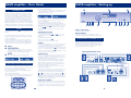
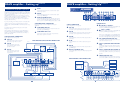
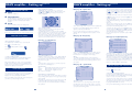
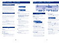
English
Français
Deutsch
Integrated Amplifier
Power Amplifier
DAVE Amplifier
MARC Amplifier
PEMBROKE AVENUE, DENNY INDUSTRIAL CENTRE, WATERBEACH, CAMBRIDGE CB5 9PB, ENGLAND
TELEPHONE: 44+(0) 1223 203203 FAX: 44+ (0) 1223 863384 e-mail: [email protected] www.arcam.co.uk
ISSUE 1
SH080E
Thank you for choosing ARCAM
FOUR MODELS
CONTENTS
This Handbook covers 4 different models, as follows:
For ease of use, this handbook has been divided into 4 sections.
An integrated amplifier
Integrated amplifier
A power amplifier
Power amplifier
The DAVE (Digital Audio Video Entertainment) amplifier
DAVE (Digital Audio Video Entertainment) amplifier
The MARC (Multi Area Remote Control) amplifier
MARC (Multi Area Remote Control) amplifier
Each of the sections has a short introduction to the product,
followed by an 'User Guide' which is primarily for users who have
had their system installed by their dealer or supplier.
Following the 'User Guide' is a section describing 'Advanced
Features' (depending on the complexity of the product).
Finally for customers wishing to set up their own system, a section
called 'Setting Up'.
IMPORTANT NOTES
SAFETY
There are 19 safety items, set out on page 25 of this Handbook.
For your own safety, and to ensure that your amplifier works
properly, we strongly recommend that you read them.
Integrated amplifier
User Guide
Using the Remote Control Handset
Advanced features
Setting up
Bi-wiring your speakers
Bi-amping
SOUND CUTS OUT FOR NO APPARENT REASON
If the temperature of the internal heatsinks rises above a safe level,
then a thermal cut out inside the amplifier will operate.
The POWER INDICATOR on the front panel will turn orange and
the protection system will temporarily remove the power to the
speakers.The system will reset itself as the heatsinks cool down.
When playing a heavily recorded CD it is possible to drive the A22
at full power despite the fact that the volume is not at maximum.
This is because of the high output voltage from a CD player.
4
5
6
7-8
9
10
Power amplifier
User Guide
Setting up
11
12
Integrated and Power amplifiers - Technical Specifications
13
AMPLIFIER DOESN’T SWITCH BACK ON
All amplifiers have a 'protection mechanism' which will be
activated if you switch the unit on again immediately after turning it
off.The mechanism may stop it being turned back on.
If the mechanism activates, wait 30 seconds, then try again.
DAVE amplifier
(HOME THEATRE MODULE)
User Guide
Setting up
Advanced features
Remote Control Handset
14
15-19
20
21
MARC amplifier
(MULTI AREA MODULE)
User Guide
Advanced Features
22-23
24
Safety Guidelines
Guarantee
3
25
26
Integrated amp - Using the Remote Control
Integrated amplifier - User Guide
7
Circled numbers in the text, e.g.
, refer to the numbers on the
pictures. If your integrated amplifier HAS NOT been installed for
you, you should read the section entitled ‘Setting up’ before using the
‘User Guide’.
dp
dq
do
If you have an integrated amplifier or MARC amplifier, you will have a Remote Control
similar to the one shown below.
This CR-389 Remote Control gives access to all functions available on the front panel
of FMJ amplifiers. It also has controls to operate Arcam CD players, AM/FM tuners
andDAB tuners.
The Remote Control transmits Philips RC-5 type codes.
DAVE REMOTE CONTROL
If you have a DAVE amplifier, you will have the the CR9000
Remote Control as shown in the DAVE amplifier section
of this handbook.That Remote Control allows you to
operate the integrated amplifier plus some basic functions
of an Arcam or Philips based CD player or Tuner.
A22 INTEGRATED AMPLIFIER
Vol
olum
ume
CD
2 TAPE 1
MODE
CONFIRM RECORD CONTROL
cn co cp cq
PHONO/AUX
CD
cr
DVD
VCR
PROCESSOR
SP1
SP2
PHONES
POWER
ct dk dl dm dn
cr
VOLUME
Adjusts the volume level of the loudspeakers, pre-amp out
and headphones.The volume can also be controlled with
the Remote Control Handset. As the volume knob is not
motorized the knob will not move when adjusted remotely.
If you spin the knob quickly it will not change the volume.
This is to prevent accidentally setting the volume too high.
NOTE ON VOLUME CONTROL SETTINGS
It is important to realise that the position of the volume
control is not an accurate indication of the power delivered
to your loudspeakers. The amplifier will often deliver its full
power long before the volume control reaches its maximum
position particularly when listening to heavily recorded
compact discs.
However the amplifier also has to be capable of giving full
power output from much lower level sources, such as tuners
and cassette decks. Using these sources, the volume control
setting may be much higher before distortion (audible
overload) sets in.
A microprocessor is at the heart of the amplifier.
It performs several important functions. It switches the amplifier on
or off from standby mode and mutes the two sets of speakers
individually as well as the pre-amp output. It is also responsible for
the remote bus and infra red remote input. Parameters can be
selected, and displayed, on the built in graphic display enabling easy
set up of the amplifier and simple source selection. In addition, the
amplifier uses LED markers to indicate the primary source which is
in use. In addition to a full suite of audio line level inputs, there is
also a high quality optional MM/MC phono stage.To protect your
amplifier, the microprocessor monitors the heatsink temperature
and RF content of the speaker outputs. In the event of the amplifier
being over driven, it can activate the automatic speaker protection
circuits and it can report fault conditions to the main display.
IN USE
do
AV
cs
INTRODUCTION
dn
TUNER
POWER
Switches the unit on and off.The unit can also be switched
into ‘standby’ by use of the remote control handset.
BALANCE
Press CONTROL
, turn the volume knob to the
desired balance, then press CONTROL again to fix the
balance you have selected.
cq
POWER INDICATOR
This will initially glow amber. After a few seconds, it will glow
green. When the indicator glows amber, the speakers are
disconnected and an internal protection circuit is activated.
The power indicator will turn red if the unit has been put
into standby mode by use of the remote control.
Under certain conditions the power indicator may flash and
a fault condition will be shown on the display
. If this
happens you should unplug the mains lead of the unit and
leave the unit for a few minutes before re-connecting.
If the fault condition persists unplug and contact your Arcam
dealer.
cq
dp
dk
SP1
Selects or de-selects the main (upper) pair of speakers.
Push the button in to select.
dl
SP2
Selects or de-selects the secondary (lower) pair of speakers.
Push the button in to select.
Important note: If both switches are turned off the amplifier
will appear not to work, as all speakers will be switched off!
cs
ENTERTAINMENT (SOURCE) SELECTORS
These buttons select the source (i.e. Radio (TUNER),
Compact Disc (CD) etc. you wish to listen to.
dq
REMOTE RECEIVER
The remote receiver is behind the FMJ badge.
Make sure the remote receiver is not covered or signals
from the Remote Control Handset will not be received.
dm
4
CONTROL
This button cycles (or steps) through the functions that can
be controlled by the volume knob.This can be either
volume (the default setting) or balance. If you have a
DAVE or MARC, there are several other functions.
Refer to those sections of this handbook.
HEADPHONES SOCKET
Accepts headphones rated between 8 ohms and 2k ohms
fitted with a 1/4” stereo jack plug. If you wish to listen on
headphones only, use SPl and SP2 (if necessary) to mute the
speakers.The headphone socket is always active.
POWER/STANDBY
Toggles the amplifi er between standby
mode and full power mode.The power
indicator light next to the power button
on the front panel is red if the amplifier
is in standby, amber while the amplifier is
powering up (this only takes a few seconds)
and green when the amplifier is powered up.
TUNER
These buttons are used to control tuner
functions.
Note that the FM/DAB lights indicate into
which mode you are switching the remote
control.The lights only illuminate for five
seconds to conserve battery power.
If neither light is illuminated this does not
mean that the remote control is not
working!
SP1 AND SP2
These buttons allow you to select and
deselect the main(SP1) and secondary
(SP2) sets of speakers attached to your
amplifier (see page 4).
DISP
Cycles through the settings ‘Bright’, ‘Off ’ and
‘Dim’.Turning the display ‘Off ’ generally
gives a slight improvement in sound quality.
OTHER AMPLIFIER FUNCTIONS
Note that greyed-out buttons on the
remote control diagram are of use with
other Arcam amplifiers.
VOLUME AND (MUTE)
Press ‘+’ to increase volume or ‘–’ to
decrease the output volume of the amplifier.
Press ‘ ‘ to mute the speaker connections
and preamp outputs. Both tape outputs and
the headphone socket remain active. Mute is
disabled either by pressing ‘ ‘ again, or by
adjusting the volume.
SOURCE SELECTION BUTTONS
These operate in the same way as the
source selectors on the front panel of your
integrated amplifier.
CD CONTROLS
These offer basic controls of Arcam CD
players, such as the FMJ CD23.
Don’t forget to fit the two AAA batteries
supplied and ensure they are inserted
correctly into the back of the remote
control before using it.
The Remote Control sends a message to an
infrared receiver which is located behind the
FMJ badge on the front of the amplifier.
Do not place anything in front of the badge
or the Remote Control may not work.
5
Integrated amp - Setting up
Integrated amp - Advanced features
dp
dq
do
CONNECTING TO A POWER SUPPLY
CAUTION
Your amplifier generates heat in use. It is therefore most important
to ensure adequate ventilation and not to obstruct the ventilation
slots on the top of the unit as this could cause overheating.
A22 INTEGRATED AMPLIFIER
Vol
olum
ume
CD
2 TAPE 1
MODE
CONFIRM RECORD CONTROL
PHONO/AUX
CD
cr
cn co cp cq
AV
cs
IN USE
cp
TUNER
ct
TAPE RECORDING
Note:The integrated amplifier must be fully powered up in
order to record. Both sets of tape sockets are identical in
sensitivity and suitable for use with almost any type of
recorder (cassette, hi-fi VCR, reel to reel, DAT, etc.) The
entertainment source selected (i.e. Radio (TUNER),
Compact Disc (CD) etc. will automatically be the signal you
record (and is sent to both the VCR and PROCESSOR
RECORD output sockets) unless you select another source.
To select another source, press RECORD.The display will
first show 'RECORD SOURCE'. Select an alternative input
by pressing the appropriate button, (i.e. Radio (TUNER),
Compact Disc (CD) etc.Your selected choice will show in
the display.The display will indicate the selected recording
option for a few seconds and then revert back to showing
the volume bar graph. Press ‘RECORD’ twice to go back to
'RECORD SOURCE'. If you are using the TAPE 1 sockets in
processor mode.The signal selected will not go to both the
VCR and PROCESSOR RECORD output sockets but go to
the VCR/TAPE 2 instead.This RECORD button can also be
used as a ‘second zone’ selector, sending (a source signal at
line level) to a second amplifier operating in another room
in the house.
DVD
VCR
PROCESSOR
SP1
SP2
PHONES
1
PROCESSOR/TAPE 1
This is tape loop to monitor a recording made on a 3 head
cassette deck. It can also be used to connect to an external
surround decoder such as the Arcam Xeta 2. Selecting this
input overrides the other source selectors
.
To play back or to monitor the recording from a cassette
deck attached to the PROCESSOR/TAPE 1 input press the
processor button
. ‘TAPE’ is shown on the display.
For use with an external processor the A22 can be put
into processor mode by first selecting PROC and then
whilst holding in the MODE button
press the PROC
button
again.The display will now show 'PRO' in place
of 'TAPE'. If the processor you are using is an Arcam Xeta 2
then press the PROC button again while holding in the
MODE button so that 'PRO2' is displayed.
ct
ct
Once in 'PRO2' mode the AV,TAPE 1,VCR and DVD
buttons on the CR235 remote control will have no effect.
This is because the Xeta 2 will also respond to these
Remote Control codes and switch to the wrong input.
If you want to change the input back for use as a normal
tape input hold the MODE button in and press the
PROCESSOR button until ‘TAPE’ appears on the display.
CAUTION: Do not set the integrated amplifier in processor mode
if you have a cassette deck or other line level source attached to
the PROCESSOR/TAPE 1 input.This is because selecting processor
mode input will send a fixed volume signal straight into the power
amplifier which could damage your loudspeakers.
ct
NOTE: If you are using the integrated amplifier with an external
processor, via the PROCESSOR/TAPE 1 loop you must set the volume of the integrated amplifier so that you can see at least one
segment of the volume level bar graph before switching to the
PROCESSOR input. If you fail to do this you will not hear any
sound from the speakers attached to the integrated amplifier.To
obtain a sound again, reselect another input eg CD and turn the
volume up slightly.
Then reselect the PROCESSOR input.
cn,co
MODE & CONFlRM
These buttons are only for use with optional modules such
as the DAVE or MARC amplifiers.
They have no function on their own in normal use on the
basic integrated amplifier although MODE can be
used to select processor mode, as described below.
6
If your mains supply voltage is different, consult your Arcam dealer
or Arcam Customer Support on 01223 203203.
Now connect your loudspeaker’s black (negative/-) terminals to the
black (negative/-) terminal on the amplifier.
PLUGGING IN
Push the plug (IEC line socket) of the cable supplied with the
amplifier, into the socket
(POWER INLET) in the back of the
amplifier. Make sure it is pushed in firmly.
Push the plug on other end of the cable into your power supply
socket.
Ensure that no stray strands of inner wires are allowed to touch
another cable or the amplifier’s casing. This can cause a short
circuit and damage your amplifier! Two pairs of speakers may be
connected at the same time provided each pair is rated between 8
and 16 ohms. If one or both pairs have an impedance of less than
8 ohms, the combined load ‘seen’ by the amplifier will fall below 4
ohms and could cause an overload. The overload protection
circuit will engage and the amplifier will not work.
2
1
cn
The volume level of the integrated amplifier will now be
fixed so that you can use the volume control of the
external processor as a master volume control.
Using the volume or mute buttons on the remote handset
or the front panel control knob will have no effect whilst in
processor mode.The unit will return to processor mode
whenever
is pressed.
cp
Connect your loudspeakers so that the red (positive/+) terminal
on each loudspeaker is connected to the red (positive/+) terminal
on the amplifier. Your loudspeaker cables may be marked to show
polarity (negative/- and positive/+), if not, then the positive
terminal can usually be identified by a ridge or coloured
marking.
Check that your mains supply voltage agrees with the voltage
setting indicated on the rear panel of the amplifier at
.
cs
TAPE TO TAPE COPYING (DUBBING)
The integrated amplifier allows two way tape dubbing from
TAPE 2 to TAPE 1 but NOT TAPE 1 to TAPE 2. For example,
to copy from a cassette recorder connected to the
VCR/TAPE 2 sockets to a cassette recorder connected to
TAPE 1, first use the RECORD selector
on the
integrated amplifier to select 'RECORD :VCR'.This routes
the TAPE 2 signal to TAPE l’s output.Then set the tape
recorder connected to TAPE 1 sockets into its
‘record’ mode and the other to ‘playback’ mode to enable
the transfer to take place. If you wish to monitor the transfer
while it is taking place select TAPE using the
TAPE1/PROCESSOR button
.
Connect the right hand speaker to the terminals on the back of
your amplifier marked R and the left speaker to the terminals
marked L.
WRONG PLUG ?
If the plug supplied with the amplifier does not fit your power
supply, see the section entitled ‘Safety Guidelines’ for changing a
plug, or contact your dealer to obtain a suitable power cord.
POWER
ct dk dl dm dn
ct
CAUTION
Do not over tighten the loudspeaker terminals or use a wrench,
pliers, etc., as this could cause damage to the terminals which will
not be covered under warranty.
230V
POWER INLET
+ R –
+ L –
2
IEC LINE SOCKET
+
CONNECTING TO LOUDSPEAKERS
HF
–
+
HF
–
Your amplifier is fitted with loudspeaker terminals,
to BFA, (British Federation of Audio) standard specification.
RIGHT SPEAKER
LOUDSPEAKER
TERMINALS
The terminal will accept spade terminals, bare wires or a BFA plug.
BFA plugs are available from your Arcam dealer. To connect a bare
wire or spade terminal unscrew the red (or black) part of the
loudspeaker terminal first.
Insert the wire or spade terminal and screw it back up.
7
LEFT SPEAKER
Continued
Integrated amp - Setting up
4
5
Bi-wiring your speakers
cm
cl
PHONO OPTION
+
-
R
+
-
L
MM
MC
230V
L
SP1
GAIN
4-16 OHMS
REMOTE
IN
NORMAL
SP2
POWER INLET
CONTROL
OUT
+
R
–
+
L
–
L
L
L
R
R
R
PWR IN
PRE OUT
LOW
R
RECORD
OUT
PLAY
IN
PROC/TAPE1
1
2 3
6
7
The use of high quality interconnect cables to and from your
integrated amplifier is recommended to ensure the best sound
quality (sonic performance).
The sockets carrying messages from your integrated amplifier are
marked L (left) and R (right), for identification. Sockets marked L
on your integrated amplifier should be connected to sockets
marked L on other equipment. All the line inputs (not PHONO)
have the same sensitivity and may be used with equipment other
than that labelled, if you need to do so.
PROCESSOR/TAPE 1 RECORD OUT
Connect this output to the input sockets of your tape deck
(RECORD) or the tape or line input sockets of your AV processor.
bl
PROCESSOR/TAPE 1 PLAY IN
Connect this input to the output sockets of your tape deck
(PLAY) or the tape or line output sockets of your AV processor.
bm
VCR/TAPE 2 RECORD OUT
Connect this output to the input sockets of your tape deck
(RECORD).
bn
VCR/TAPE 2 PLAY IN
Connect this input to the output sockets of your tape deck
(PLAY).
bo
DVD
Connect this input to the audio outputs of a DVD player.
bp
AV
Connect this input to the audio outputs of an Audio-Visual
product such as a VCR, Laserdisc player or Nicam tuner.
bq
TUNER
Connect this input to the audio outputs of your radio tuner.
br
CD
Connect this input to the audio outputs of your CD player
or DAC (digital to analogue convertor).
bs
PLAY
IN
VCR/TAPE2
AUX
DVD
AV
TUNER
CD
PHONO OPTION - Please note:The phono inputs are on a
separate plug-in module which your Arcam dealer or
distributor can supply and fit.This module is compatible with
most high output moving coil and moving magnet cartridges
(MM) and low output moving coil cartridges (MC). MM or
MC is selected via an internal switch.Your cartridge type
should be specified when the module is fitted.
CONNECTING TO OTHER EQUIPMENT
bk
RECORD
OUT
bkblbmbnbobpbqbrbs btck
8 9
bt
MC
For connecting a turntable fitted with a low output moving
coil (MC) cartridge.
cl
GROUND TERMINAL
For connecting your turntable earth lead (if fitted).
3
REMOTE CONNECTION
These connections are for use in multi-room installations. In
normal use there is no need to make any connections to
these sockets. If you are biamping with an Arcam power
amplifier see section ‘Remote Switching’ for details of how to
power both units on/off simultaneously.
9
AUX
Connect this input to the audio outputs of any unit with a
line level output, eg. tape deck, tuner etc.
Please note:The AUX inputs MUST NOT be used if the
phono module is fitted. When the phono module is fitted
AUX becomes an output carrying the equalised phono
signal at line level.
8
MM
For connecting a turntable fitted with a high output moving
coil or a moving magnet (MM) cartridge.
ck
8
SHOWN BELOW IS THE BI-WIRING CONFIGURATION
USING ONE SET OF SPEAKER CONNECTIONS ON
THE INTEGRATED AMPLIFIER.
Bi-wiring improves the sound of your system because it divides the
high and low frequency signal currents into separate speaker
cables.This avoids signal distortions arising from the high and low
frequency currents interacting with one another within a single
cable, as in conventionally wired systems.
GAIN
This switch allows you to change the sensitivity of the
amplifier to match the gain when biamping to external
power amp.The normal position is suitable for use when
biamping with Arcam power amplifiers.
The low gain position is suitable for certain specialist
home theatre systems. Before making any connections
ensure that all equipment is switched off at the mains wall
socket.
PRE/POWER CONNECTIONS
PWR AMP IN - To use your integrated amplifier just as a
power amplifier, connect the output of your pre-amplifier to
the PWR AMP IN sockets.The integrated amplifier’s internal
selector switch must be changed to disconnect the pre-amp
stages of the unit. Contact your dealer or Arcam for more
details. Under these circumstances it has exactly the same
specification and performance as an Arcam power amplifier.
PRE-AMP OUT - To use your integrated amplifier as a
preamplifier, connect the PRE-AMP OUT sockets to the
input sockets of your power amplifier. With a power
amplifier of the correct gain (e.g. An Arcam P25)
this allows you to bi-amplify ('bi-amp') suitable loudspeakers,
giving significant improvements in sound quality (see section
on BI-WIRING/ BI-AMPING).
INTEGRATED AMPLIFIER
YOU WILL NEED
Speakers which have four terminals (connection points for
wires) on the back of each one. That’s eight in total.
If you have four terminals on each speaker they will be marked HF
(High frequency) and LF (Low Frequency).
Loudspeaker cables
Two pairs of loudspeaker cables per loudspeaker (which may be
joined at the amplifier end if your amplifier only has one pair of
output terminals per channel).
Or, a suitably terminated cable set (group of bound cables,
probably prepared by your dealer) capable of being used for
bi-wiring in one length.
WARNING
Do not make any connections to your amplifier while it is switched
on or connected to the mains supply. Please check all connections
thoroughly, make sure bare wires or cables are not touching the
amplifier in the wrong places (shorts) and you have connected
positive (+) to positive (+) and negative (-) to negative (-) before
attempting to re-connect the mains power supply.
Always ensure that the volume control on your amplifier is set to a
minimum before switching on.
+ R –
+
+
HF
LF
+ L –
–
+
–
+
HF
LF
–
–
LEFT SPEAKER
RIGHT SPEAKER
If you are using one pair of bi-wireable speakers and another pair
that is not, you should connect your bi-wireable speakers as shown
above, to just one set of the amplifier terminals. This leaves the
second set of terminals to connect the non bi-wireable speakers to.
HOW TO BI-WIRE LOUDSPEAKERS
SHOWN BELOW IS THE BI-WIRING CONFIGURATION
USING BOTH SETS OF SPEAKER CONNECTIONS ON
THE INTEGRATED AMPLIFIER.
1.
Remove the wire clips or bars which connect the pairs of terminals
together (terminal links) on each of the red and black terminals
on the rear of your loudspeakers.
INTEGRATED AMPLIFIER
THIS IS ESSENTIAL OR DAMAGE TO YOUR AMPLIFIERS
MAY RESULT WHICH IS NOT COVERED UNDER
WARRANTY.
R
+
2.
Connect the cables as shown in one of the pictures opposite,
dependant on the cables and the number of free amplifier
terminals you have, ensuring correct polarity at all times.
The positive (+) terminals on the right loudspeaker must go to the
positive (+) terminals on the right of the amplifier and the negative
(-) terminals on the right loudspeaker must go to the negative (-)
terminals on the right of the amplifier etc.
+
+
HF
LF
+
–
–
+
–
+
RIGHT SPEAKER
9
L
–
HF
LF
–
–
LEFT SPEAKER
Bi-amping
Power amplifier - User Guide
Always switch on the integrated amplifier and allow it to stabilise
(indicator light turns green) before switching on the power
amplifier.
At the end of a listening session the power amplifier should always
be turned off first.
The performance of your system can be further enhanced over
that achieved with bi-wiring, by extending the same principal one
stage further to include separate amplification for the low and high
frequency speaker drive units in each loudspeaker box.
YOU WILL NEED
Speakers which have four terminals (connection points for
wires) on the back of each one. That’s eight in total.
If you have four terminals on each speaker they will be marked HF
(High frequency) and LF (Low Frequency).
Two stereo amplifiers
Generally, one of these would be an Arcam integrated amplifier
and the other an Arcam power amplifier.
Loudspeaker cables
Two pairs of loudspeaker cables per loudspeaker or a suitably
terminated cable set (group of bound cables, probably prepared by
your dealer) capable of being used for bi-amping in one length.
Interconnect cables
One pair of high quality interconnect cables.
P25 POWER AMPLIFIER
High quality interconnect cables should be used between the
integrated amplifier and power amplifier.
The use of high quality interconnect and speaker cables in your
system is essential to obtain good sound quality.
Contact your dealer for further details.
SHOWN BELOW IS THE BI-AMPING CONFIGURATION
RECOMMENDED FOR THE ALPHA AMPLIFIERS COVERED IN
THIS HANDBOOK
INTEGRATED AMPLIFIER
If one of your amplifiers is an integrated amplifier it is best to use
that one connected to the high frequency (HF) speaker terminals
(and their respective drive units) whilst the power amplifier (outboard amplifier) is used to drive the low frequency (LF) speaker
terminals (and their respective drive units).
+ R –
+ L –
L
R
RIGHT
SPEAKER
+
+
HF
LF
LEFT
SPEAKER
–
+
–
HOW TO SET UP A BI-AMPED SYSTEM
R
+
1.
Remove the wire clips or bars which connect the pairs of terminals
together (terminal links) on each of the red and black terminals
on the rear of your loudspeakers.
+
HF
LF
INTERCONNECT
CABLES
WARNING
Do not make any connections to your amplifier while it is switched
on or connected to the mains supply. Please check all connections
thoroughly, make sure bare wires or cables are not touching the
amplifier in the wrong places (shorts) and you have connected
positive (+) to positive (+) and negative (-) to negative (-) before
attempting to re-connect the mains power supply. Always ensure
that the volume control on your amplifier is set to a minimum
before switching on.
do
dq
–
–
L
–
+
L
–
SP1
The power amplifier shares all of the electronic and structural
advantages of its sister integrated amplifier.
It can also be upgraded from stereo mode to three channel
audio by the addition of a ‘PAM’ (Power Amp Module.
This module offers extra terminal connectors together with a
third set of pre-out and power-in phono sockets to turn the
power amplifier into a 3 x 100 watts (RMS per channel into 8
Ohms) amplifier suitable for Home Cinema or Karaoke use.
Contact your dealer for further details.
IN USE
dn
Circled numbers in the text, e.g.
, refer to the numbers on the
pictures.
If your power amplifier has not been installed for you, you should
read the section entitled ‘Setting up’ before using the ‘User Guide’.
dn
POWER
Switches the power on and off.
do
POWER INDICATOR
This will initially glow orange. After a few seconds, it will
glow green. When the indicator glows orange, the speakers
are disconnected and an internal protection circuit is
activated.
dk
SP1
Push the button in to select the main (upper) pair of
speakers. Push the button in to select.
dl
SP2
Selects or de-selects the secondary (lower) pair of speakers.
Push the button in to select.
POWER AMPLIFIER
THIS IS ESSENTIAL OR DAMAGE TO YOUR AMPLIFIERS
MAY RESULT WHICH IS NOT COVERED UNDER
WARRANTY.
2.
Connect the cables as per one of the diagram opposite,
ensuring correct polarity at all times. The positive (+) terminals on
the right loudspeaker must go to the positive (+) terminals on the
right of the amplifier and the negative (-) terminals on the right
loudspeaker must go to the negative (-) terminals on the right of
the amplifier etc. You also need to make a connection from the
PRE AMP OUT sockets of your integrated amplifier, or preamplifier,
to the POWER AMP IN sockets of the power amp.
The SPl & SP2 switches will both connect/disconnect
speakers attached to the 3rd channel option
if fitted.
bm
Important note: If both switches are turned off the amplifier
will appear not to work, as all speakers will be switched off!
dm
3.
Use the interconnect cables to connect the PRE-AMP OUT
sockets
of the integrated amplifier to the PWR AMP IN sockets
of the power amplifier.
9
10
PHONES
POWER
dk dl dm dn
INTRODUCTION
R
SP2
HEADPHONES SOCKET
Accepts headphones rated between 8 ohms and 2k ohms
fitted with a 1/4” stereo jack plug. If you wish to listen on
headphones only, use SPl and SP2 (if necessary) to mute the
speakers.The headphone socket is always active.
11
Power amp - Setting up
4
Amplifiers - Technical specifications
bn
5
TECHNICAL SPECIFICATIONS
Output power (20Hz-20kHz at 0.5%THD)
8ohms, both channels
8ohms, single channel, 1kHz
4ohms, single channel, 1kHz
Harmonic Distortion, 100W, 8Ω at 1kHz
Peak current rating
L/R Crosstalk
Frequency response ± 0.5dB
Input impedance
Input sensitivity
LINK
+
230V
-
R/CH1
+
-
L/CH1
+
EXTERNAL
PWR AMP LINK
OUT
IN
SP1
GAIN
IN
NORMAL
4-16 OHMS
CTR/CH3
-
CTR/CH3
SP1
L
PWR
IN
R
PRE
OUT
GAIN
NORMAL
4-16 OHMS
CONTROL
OUT
SP2
+
POWER INLET
1
2 3
-
R/CH1
+
6
-
L/CH1
SP2
LOW
LOW
bk bl
8 9
7
PWR AMP IN
Connect this input to the output sockets of your
pre-amplifier or the PRE-AMP OUT sockets of an integrated
ampIifier.
bn
MONO LINK
The integrated amplifier can be adapted to provide two
mono loudspeaker outputs from a single input.
Pull out the U-link
supplied and use it to connect the
LINK OUT sockets together.
Utilising one power amplifier per loudspeaker will enable you
to bi-amplify bi-wireable loudspeakers. This is particularly
beneficial for top quality stereo installations with a separate
pre-amplifier, or for the left, centre and right channel loud
speakers in a five speaker Dolby Pro Logic™ or Dolby
Digital™ system.
Contact your Arcam dealer for more detailed information.
CTR/CH3
-
bm
P25 REMOTE SWITCHING
By making a connection from the 'control out' socket
of the A22 to the 'control in' socket
of the P25 power
amplifier you can use the A22 to control the power mode
of the power amplifier. If configured in this way the front
panel power button of the A22 (or remote control standby
button) will switch both amplifiers on or off simultaneously.
This facility allows you to hide the power amplifier out of
sight and still be able to control its functions.
The connecting cable required is a 3.5mm to 3.5mm jack
lead (stereo or mono) and it is possible to connect several
P25 power amplifiers to an integrated A22 by 'daisy chaining'
from 'control out' of one into the 'control in' of the next as
shown in the diagram at the bottom of the page.
CONNECTING TO POWER, SPEAKERS, and
OTHER EQUIPMENT
Follow the guidelines for the integrated amplifier in this handbook.
9
+
3
3
bn
bk bl bm
THIRD CHANNEL OPTION
,
,
This option enables you to have a 5 channel amplifier when
used with a suitable integrated amplifier, to create a high
quality Home Cinema setup.
The third channel can be used to drive the centre speaker.
For connection details see DAVE amplifier ‘Setting up’.
Please contact your dealer for availability of this module.
DAISY CHAIN
The power amplifier is capable of driving further power
amplifiers (or any other power amplifier), to drive more
speakers (e.g. those in other rooms or tri-amplified speakers
etc). Connect the extra power amplifier inputs to the LINK
OUT sockets on the power amplifier, left to left, right to right.
Now you have finished ‘Setting up’, return to the ‘User Guide’.
Inputs from Pre-amp
DAISY CHAIN WIRING GUIDE
INPUTS
Line inputs:
Sensitivity
Noise (CCIR) ref. rated power
Input impedance
Overload margin
A/V loop input (A/V mode):
Sensitivity
Input impedance
Power amp in:
Sensitivity
Input impedance
Phono board (if fitted):
Sensitivity
Noise (CCIR) ref. rated power
Input impedance
Overload margin
OUTPUTS
Pre-amplifier Output:
Nominal output level
Maximum output level
Output impedance
Tape/ AUX output:
Output impedance
Headphones:
Maximum output level into 600Ω
Output impedance
Mains voltage
POWER AMPLIFIER
+
R/CH1
-
+
L/CH1
-
EXTERNAL
PWR AMP LINK
IN
OUT
SP1
L
4-16 OHMS
OUT
SP2
PRE
OUT
R
+
R/CH1
-
+
L/CH1
-
+
R/CH1
-
+
L/CH1
-
CTR/CH3
-
SP1
PWR
IN
IN
CONTROL
+
CTR/CH3
4-16 OHMS
SP2
+
CTR/CH3
-
+
CTR/CH3
-
POWER AMPLIFIER
EXTERNAL
PWR AMP LINK
IN
OUT
SP1
IN
L
4-16 OHMS
CONTROL
OUT
SP2
R
+
R/CH1
-
+
L/CH1
-
12
Power consumption(max)
Dimensions W/D/H mm.
Weight net
Weight packed
Supplied accessories
INTEGRATED AMPLIFIER
POWER AMPLIFIER
100W
110W
170W
0.02% typical
±25A
-80dBV at 1kHz
-
100W
110W
170W
0.02% typical
±25A
10Hz-20kHz
7.5kΩ
740mV (Normal Gain)
1.0V (Low Gain)
160mV
-100dB
10kΩ
>30dB
-100dB
-
680mV
7.5kΩ
-
740mV (Normal Gain)
1.0V (Low Gain)
7.5kΩ
-
2.6mV MM, 26µV MC
-79dB MM, -73dB MC
47kΩ MM, 300Ω MC
35dB
-
800mV
8V
50Ω
-
50Ω
-
8V
100Ω
230V ± 12%
115V ± 12%
800VA (8VA in standby)
430x380x110
10.9 kg
13.1 kg
Mains lead
Remote Control Handset
2 x AAA batteries
8V
100Ω
230V ± 12%
115V ± 12%
800VA (8VA in standby)
430x350x110
10.6 kg
12.5 kg
Mains lead
E&OE
CTR/CH3
SP1
PWR
IN
PRE
OUT
4-16 OHMS
SP2
+
CTR/CH3
-
13
DAVE amplifier - User Guide
or....USING THE FRONT PANEL
Press the appropriate button showing the abbreviated name of the
source entertainment you want to listen to, eg CD,TUNER etc.
The display will show this sequence.
INTRODUCTION
The DAVE (Digital Audio Video Entertainment) module,
transforms the integrated amplifier into a state-of-the-art Audio
Visual system. By connecting it via a power amplifier an extra 3
channels can be added, enabling 3 extra loudspeakers (5 in total).
The extra dimension of truly high quality sound makes movies,
sport and your favourite TV programmes a much more exciting
experience.The DAVE is capable of providing a level of sound
quality which will match a modern cinema.The DAVE will accept
Stereo, Dolby Digital, DoIby Pro Logic, Dolby 3 Channel, DTS, and
Digital Stereo signals.You are recommended to read the integrated
amplifier ‘User Guide’ first, for an introduction to the many features
of the integrated amplifier which are identical to the DAVE amplifier.
Vol
olum
ume
cr
STANDBY
You can leave your DAVE turned on when temporarily not in use
by pressing the POWER button on the remote control.You will
see the word 'Standby' in the front panel display for a few
seconds.Then the power indicator light
on the front panel, will
turn red.To return to full power, ready for use, press the POWER
button again.The power indicator light
will initially glow orange,
then turn to green.The unit is ready for use.
POWER
Switches the amplifier on.
POWER INDICATOR
This will initially glow orange. After a few seconds, it will
glow green. When the indicator glows orange, the speakers
are disconnected and an internal protection circuit is
activated.
DISPLAY
When the amplifier is turned on the display shows:
Vol
olum
ume
ARCAM Home Theatre
do
do
SPEAKER SET UP
There are several adjustments which can be made to your speaker
trims if you are listening from a different position in the room.
It is possible to adjust the gain of the centre and rear channels by
+/- 12dB using the remote control handset.
A pink noise generator is available which will cycle through the
available speakers (at 2 second intervals) making it possible to
adjust trim levels and confirm good connections between the
speakers and the amplifiers.This can be accessed at any time by
pressing the TEST [ALT] button on the remote.
It can also be accessed in setup mode (see the section of this
handbook called 'Setting up')
An.. Pro
logic
CHOOSING YOUR ENTERTAINMENT
Make sure that the CR9000 has its batteries installed. Make sure it
is in AUDIO mode by pressing the ‘AUD’ button at the top of the
Remote Control. AUDIO will show in the display.
Make sure that the source equipment (eg DVD player, Satellite
receiver etc.) is turned on.
MODE
CONFIRM RECORD CONTROL
PHONO/AUX
CD
TUNER
cr
cn co cp cq
AV
DVD
VCR
cs
PROCESSOR
1
PHONO
2
AUX
4
CD
5
TAPE 1
6
AV
1
DISPLAY
7
DVD
8
VCR
9
SAT
1
FUNCTION
+10
0
ENTER
ALT
PHONES
SP2
REMOTE HANDSET
A CR 9000 programmable and learning Remote Control.
A separate Operating Manual is supplied with this Remote Control.
CREATING YOUR 5 CHANNEL SET UP
To create a 5 speaker set up you should first connect your DAVE
amplifier and power amplifiers to the five speakers as shown
above. In this setup the integrated amplifier is used to power your
front left and right speakers and the power amplifier is used to
power the centre and the rear two speakers.
DAVE AMPLIFIER WIRING GUIDE
AUDIO OUT
INTEGRATED AMPLIFIER
+
-
R
+
-
L
CENTRE
SURR.L
SUB
SURR.R
SP1
RIGHT FRONT
SPEAKER
LEFT FRONT
SPEAKER
4-16 OHMS
REMOTE
IN
SP2
CONTROL
OUT
+
–
R
+
–
L
POWER AMPLIFIER
NIGHT TIME LISTENING
This reduces the overall loudness of the program being listened to
whilst still making it easy to hear the voices and effects.To select
press NIGHT on the remote handset. 'Late Night mode On' will
be displayed for a few seconds.To deselect press NIGHT again.
3
FAV
TUNER RESTORE
14
POWER
ct dk dl dm dn
+
R/CH1
-
+
L/CH1
-
EXTERNAL
PWR AMP MONO
IN
LINK
SP1
L
4-16 OHMS
CONTROL
OUT
SP2
R/CH1
-
+
L/CH1
LEFT REAR
SPEAKER
CENTER
SPEAKER
15
-
4-16 OHMS
SP2
+
-
RIGHT REAR
SPEAKER
CTR/CH3
SP1
PRE
OUT
R
+
+
CTR/CH3
PWR
IN
IN
PRE
CH
EXIT
SP1
DAVE 10 PARTS CHECK
Your DAVE amplifier is supplied with:
You should adjust the trims so that all speakers produce the same
volume at your normal listening position. Adjust speaker trims
whilst the noise is being generated by pressing the TRIM buttons
and
for the centre speaker and the REAR buttons
and
for the rear speakers. If you adjust a speaker trim then the
noise will stay on the channel being adjusted until shortly after you
have finished making the adjustment. See also 'Using the Menus' in
the 'Setting up' section of this handbook.
USING THE REMOTE CONTROL
Press the appropriate button showing the abbreviated name of the
source entertainment you want to listen to, eg CD,TUNER etc.
STOP
CD
2 TAPE 1
CHANGING THE VOLUME
USING THE REMOTE CONTROL
Press the VOL buttons showing
OR
on the remote
control.The volume you set will be shown in the display on the
front panel.
or....USING THE FRONT PANEL
Adjust the volume control knob
.
The volume you set will be shown in the display.
WHAT CAN DAVE DO?
The DAVE is supplied with an Arcam learning programmable
Remote Control which can operate all the components of your
Audio Visual system.For full details of how the CR 9000 Remote
Control works, consult the Operating Manual supplied with it.
dp
A22 INTEGRATED AMPLIFIER
cn
dn, refer to the numbers on the
do
Source CD
An.. Pro
logic
The green LED light on the front panel (under the source you
have chosen) will light up.
The source equipment may be either digital or analogue.
The DAVE will automatically select the best type of signal from
each specific source and programme being played.You can use the
front panel ‘MODE’ button
(press it once, twice or more) or
the MODE
buttons on the Remote Control, to override
this function and manually select the decode mode you wish
to listen to.
If your DAVE amplifier has not been installed for you, you should
read the section entitled ‘Setting up’ before using the ‘User Guide’.
dn
do
dp
dq
Vol
olum
ume
IN USE
Circled numbers in the text, e.g.
pictures.
DAVE amplifier - Setting up
ACTIVE
SUBWOOFER
CTR/CH3
-
Continued
Continued
DAVE amplifier - Setting Up
DAVE amplifier - Setting up
fm
CONNECTING TO OTHER EQUIPMENT
There are two different types of video signals. Some equipment is
manufactured to one type, some to the other. One is called either
'S Video' or SVHS (which usually has a higher quality picture), the
other is 'Composite video'.
The DAVE does not convert one to the other.You can connect
equipment sending both types of signal to your DAVE at the same
time. However, you shouldn't connect two similar pieces of
equipment (e.g. an 'S Video' Laser disc and a 'Composite video'
Laser disc at the same time).
fn
fo
If you are connecting some 'S Video', and some 'Composite video'
equipment you must connect your TV (monitor) to both the
'SVHS' and the 'COMPOSITE VIDEO' MON OUT (monitor out)
sockets.
For optimum video performance always use 75 ohm cables
designed for video use.
When watching a videotape that has a copy prohibit signal, eg
Macrovision™, the On Screen Display (OSD) may sometimes
wobble or move slightly.This is normal and does not indicate a
problem with the unit.
DAVE MODULE
AV IN
Connect this input socket to the composite video output
socket of your source.
em
SVHS
MON OUT (MONITOR OUT)
Connect this output socket to the composite video input of
your TV or monitor.You will probably need a RCA phono to
phono (or phono to SCART in Europe) video cable to do this.
S VIDEO CONNECTIONS
See the diagrams above and opposite.
ek
dr
COMPONENT VIDEO IN
Connect these input sockets to the component video out
put sockets of your DVD player.
COMPONENT VIDEO OUT
Connect these output sockets to the component video
input sockets of your TV or monitor.
DAVE AMPLIFIER COMPOSITE VIDEO WIRING GUIDE
ds
fq
AUDIO OUT
VCR IN
Connect this input socket to the
composite video output socket of
your video recorder.
AUDIO OUT
AUX IN
Connect this input socket to the
composite video output socket
of your source.
SATELLITE RECEIVER
CD PLAYER
TUNER
AUDIO OUT
DIGITAL OUT
GROUND
COMPOSITE VIDEO OUT
COMPOSITE VIDEO IN
DVD IN
AV IN
Y OUT
B-Y OUT
R-Y OUT
MON OUT
DVD IN
AV IN
VCR OUT
VCR IN
AUX IN
Y IN
B-Y IN
R-Y IN
VCR OUT
VCR IN
AUX IN
COMPONENT VIDEO
COMPOITE VIDEO
DIGITAL IN
DIGITAL IN
(DVD) 1-COAX - 2 (AV)
1- OPTICAL - 2
AUDIO OUT
CENTRE
SURR.L
SUB
SURR.R
el em en eo ep eq er
ek
eo, ep
OPTICAL 1, OPTICAL 2
Connect these input sockets to the optical digital output
sockets of your DVD player, CD player, etc.
VCR OUT
Connect this output socket to the video input socket of
your video recorder if your VCR is an S Video model.
fl, fk
COAX 1, COAX 2
Connect these input sockets to the coaxial digital output
sockets of your DVD player, CD player, etc.
VCR IN
Connect this input socket to the S Video output socket of
your video recorder if your VCR is an S Video model.
Each of these 4 digital inputs can be individually allocated to
one of these inputs: DVD, AV, AUX, CD,TUNER or VCR.
This is done in the digital input setup page in the setup menu.
AUX IN
Connect this input socket to the S Video output socket of
your source.
AV IN
Connect this input to the S Video output socket of your
source.
fr
DVD IN
Connect this input socket to the S Video output socket of
your DVD player.
fs
MON OUT (MONITOR OUT)
Connect this output socket to the S Video input of your TV
or monitor.
eq
SUB (SUBWOOFER PRE-AMP OUT)
Connect this output socket to the input socket of your
active subwoofer, if you have one.
er
SURR. R (SURROUND RIGHT PRE-AMP
OUT)
Connect this output socket to the right hand 'power amp in'
socket of the amplifier connected to your surround (rear)
speakers.
es
SURR. L (SURROUND LEFT PRE-AMP OUT)
Connect this output socket to the left hand 'power amp in'
socket of the amplifier connected to your surround (rear)
speakers.
et
CENTRE (PRE-AMP OUT)
Connect this output socket to the centre 'power amp in'
socket of the amplifier connected to your centre speaker.
DAVE AMPLIFIER S VIDEO WIRING GUIDE
SVHS
COMPOSITE VIDEO
MON OUT
AUDIO OUT
TURNTABLE
en
COMPONENT VIDEO
DIGITAL INPUTS
dt
VCR OUT
Connect this output socket to the video
input socket of your video recorder.
fo fn fm fl fk et es
fp
dr ds dt
COMPONENT VIDEO CONNECTIONS
Note: these sockets are not normally found on European
equipment.
fp
fs fr fq
DVD IN
Connect this input socket to the composite video output
socket of your DVD player.
COMPOSITE VIDEO CONNECTIONS
See the diagrams below and opposite.
el
REAR VIEW OF DAVE AMPLIFIER
AUDIO OUT
PHONO OPTION
MON OUT
DVD IN
AV IN
Y OUT
B-Y OUT
R-Y OUT
MON OUT
DVD IN
AV IN
VCR OUT
VCR IN
AUX IN
Y IN
B-Y IN
R-Y IN
VCR OUT
VCR IN
AUX IN
(DVD) 1-COAX - 2 (AV)
1- OPTICAL - 2
CENTRE
SURR.L
SUB
SURR.R
MM
L
R
R
S-VHS OUT
S-VHS IN
L
DVD PLAYER
VCR
MONITOR/TV
L
MC
R
L
S-VHS OUT
S-VHS OUT
PWR IN
PRE OUT
LASERDISC
R
RECORD
OUT
PLAY
IN
PROC/TAPE1
RECORD
OUT
PLAY
IN
VCR/TAPE2
AUX
DVD
AV
TUNER
MONITOR/TV
CD
S-VHS OUT
SATELLITE
RECIEVER
AUDIO IN
AUDIO OUT
AUDIO OUT
AUDIO IN
TAPE DECK 1
SVHS
COMPONENT VIDEO
COMPOSITE VIDEO
DIGITAL IN
(DVD) 1-COAX - 2 (AV)
1- OPTICAL - 2
AUDIO OUT
PHONO OPTION
AUDIO OUT
VCR
DVD PLAYER
MON OUT
DVD IN
AV IN
Y OUT
B-Y OUT
R-Y OUT
MON OUT
DVD IN
AV IN
VCR OUT
VCR IN
AUX IN
Y IN
B-Y IN
R-Y IN
VCR OUT
VCR IN
AUX IN
L
L
R
R
CENTRE
SURR.L
SUB
SURR.R
LASERDISC
L
COMPOSITE VIDEO IN
COMPOSITE VIDEO OUT
R
COMPOSITE VIDEO OUT
16
PRE OUT
MC
L
R
COMPOSITE VIDEO OUT
PWR IN
MM
RECORD
OUT
PLAY
IN
PROC/TAPE1
17
RECORD
OUT
PLAY
IN
VCR/TAPE2
AUX
DVD
AV
TUNER
CD
Continued
Continued
DAVE amplifier - Setting up
USING THE REMOTE CONTROL
Use [PAUSE] and [STOP] buttons to go up/down the
menu, [REW] and [FF] buttons to alter the selection on the
highlighted line, and to change menu pages when the menu
heading is highlighted.
GETTING READY FOR USE
dn
POWER
Switches the amplifier on.
do
POWER INDICATOR
This will initially glow orange. After a few seconds, it will
glow green. When the indicator glows orange, the speakers
are disconnected and an internal protection circuit is
activated.
dp
Vol
olum
ume
MENU
GUIDE
PAUSE
R
E
W
DISPLAY
When the amplifier is turned on the display shows:
ARCAM Home Theatre
DAVE amplifier - Setting up
SEL
PLAY
STOP
TO ENTER SET UP MODE
the menus in ‘Set up mode’.You can enter this mode using either
the Remote Control or the front panel.
Main
Centre
Surr
Sub
= Large/Small
= Large/Small/Not Present
= Large/Small/Not Present
= Present/Not Present
PRE
CH
USING THE FRONT PANEL
When 'Misc <PAGE>' is showing move through the 5 menu
headings using the VOLUME control.
To cycle through the items on a menu, press the CONTROL
button one, two, three or more times.To select a choice rotate the
volume control one click at a time to cycle through the available
choices. After you have cycled through each of the items on a
menu, return to <PAGE> using the CONTROL button, then you
can then use the VOLUME control to move onto other menus.
Before using your DAVE, you must set certain parameters for it on
Arcam Home Theatre
2/5 Speaker Sizes
F
F
EXIT
An.. Pro
logic
Choose between large, small or not present. Where applicable this
information is used in Dolby Digital decoding to redirect bass
signals to speakers that can handle them.
If you choose ‘Not present’ for a speaker then you will not be
given the option to set delay times for these speakers on menu
page 3/5.
Menu page 3/5 - Delay Setup
Menu page 5/5 - Digital Input Setup
Menu page 1/5 - Miscellaneous
USING THE REMOTE CONTROL
The CR9000 must be in AUDIO mode to control the unit.
Press
Press
AUD
Arcam Home Theatre
1/5 Misc.
to enter AUDIO mode.
FAV
RESTORE
followed within 2 seconds by
MENU
On Screen Display: On/Off
Decode: Auto/Analogue/Digital
Measurements: Imperial
Colour OSD: On\Off
.
You will see....
The trim levels are relative to the volume of the left and right front
speakers so if you increase/ decrease the volume using the volume
up
or down
buttons on the remote or the front panel
volume knob, the centre, rear and subwoofer levels will also change
accordingly.
To adjust the level of the centre, rear and sub (AV and stereo) use
the [REW] button to move the sound left and [FF] button to
move the sound right. m
The test noise will stay on the selected speaker whilst you are
making adjustments and then go onto the next speaker after a few
seconds.
Subwoofer
There is only one subwoofer pre-amp out on the DAVE but it is
possible to have one volume setting for home cinema use (AV)
and another for when listening in stereo mode.
To adjust the sub (AV and stereo) use the
[REW] button to
move the sound left and [FF] button to move the sound right.
You can turn the stereo sub output off by turning the level fully
down until OFF is shown on the display.
See also 'Speaker setup' in the 'User Guide' section of this DAVE
handbook.
Menu page 2/5 - Speaker Sizes
Arcam Home Theatre
5/5 dig.Input Setup
Arcam Home Theatre
3/5 Delay Setup
Distance from:
Left Front
Right Left
Centre
Right Rear
Left Rear
=
=
=
=
=
Optical 1
DVD/AV/AUX/CD/TUNER/VCR/Not connected
Optical 2
DVD/AV/AUX/CD/TUNER/VCR/Not connected
Coax1
DVD/AV/AUX/CD/TUNER/VCR/Not connected
Coax2
DVD/AV/AUX/CD/TUNER/VCR/Not
connected
m
m
m
m
m
m
Exit + Save
Select each speaker in turn and then enter the distance from the
speaker to your normal sitting position.This range is adjustable
from 0-25 feet in 1 foot steps (0-7m in 0.3m steps).
Misc
Misc
PAGE
ON SCREEN DISPLAY ON/OFF
Default is on. If you choose 'off' the on screen display (OSD) will
go off once you have saved the settings and will not show when
you adjust volume, change inputs, etc, unless you go back to the
setup menu screen again.
N.B.
To turn the OSD on again you have to go back into setup menu
and reselect 'On Screen Display On'.
or....USING THE FRONT PANEL
Hold down the MODE button and whilst still holding it down
V
press the CONFIRM
button.You will see ‘Misc <PAGE>’.
Either method will bring up a menu on the On Screen Display
(OSD) on the TV monitor connected to your DAVE module.
At the same time, the same title or selected line from the menu
will show in the display on the front panel.
DECODE MODE
Auto Automatically selects the digital source if present.
Analogue Allows selection of analogue sources only.
Digital Allows selection of digital sources only.
Auto mode is recommended.
USING THE MENUS
There are 5 menus, each has up to 7 options.
The selected menu will be appear on your 'On Screen Display' on
your TV monitor. The selected line of the menu will also be
displayed on the front panel display of the DAVE.
MEASUREMENTS - IMPERIAL/METRIC
Choose your preferred unit of measure for the distance of speakers
from your sitting position adjusted on menu page 3/5 (delay setup).
Each of the following sections starts with a picture showing what
you will see as you move through the menus.
COLOUR OSD
With OSD on the background screen for the OSD on the TV will
be blue. With OSD off the background will be grey.This latter
mode may be better in some countries that use non mainstream
video standards.
18
The DAVE module has 4 digital inputs (2 x optical, 2 x coaxial).
Each of these can be allocated to one of 6 inputs DVD/AV/AUXICD/TUNER/VCR or Not Connected. Each digital input can only be
allocated to one input e.g. if you chose Optical 1 to be for DVD
the choices for Optical 2 are now only AV/AUX/CD/TUNER/VCR
or not connected, etc. If you wish to re-allocate DVD to another
input you must first change Optical 1 to another source, e.g. AUX,
before you can allocate DVD to a different input.
DELAYS
Your DAVE automatically adjusts the channel delay times to
achieve 'coincident arrival' of sound from the speakers when you
have entered the distance from your listening position to each of
your speakers.
Menu page 4/5 - Speaker Trims
TO EXIT MENUS AND SAVE SETTINGS
Arcam Home Theatre
4/5 Speaker Sizes
Test tone
Left Front
Centre
Right Front
Left Rear
Right Rear
Sub (AV)
Sub (Stereo)
On/Off
USING THE REMOTE CONTROL
:On/Off
Press the
I--------------I--------------I
0dB
I--------------I--------------I
I--------------I--------------I
I--------------I--------------I
I--------------I--------------I
0dB
0dB
0dB
0dB
MENU
button any time.
USING THE FRONT PANEL CONTROLS
Press the front panel CONFIRM button at anytime from any menu.
Both the OSD and front panel display will then show 'Settings
Saved' for a couple of seconds to confirm this.
Your unit now has the settings stored in memory as 'Favourite
Settings'.You can choose to trim the centre and surround levels to
suit a particular movie, then restore the stored settings at any time
by pressing FAV RESTORE on the remote.
TEST TONE ON/OFF
Turn the test noise on to cycle through the speakers and adjust
the relative levels of them.The noise will continue to cycle until
turned off. Use the trim to adjust for an equal level of noise from
each speaker at the listening position.
Now you have finished ‘Setting up’, return to the ‘User Guide’.
19
DAVE amplifier - Advanced features
MODE SELECTION
VENTILATION
The following modes will be available: Stereo, Dolby Digital, DoIby
Pro Logic, Dolby 3 Channel, DTS, Digital Stereo.
Adequate ventilation MUST be provided for the DAVE amplifier,
and it is strongly recommended that it is not stacked with other
products, particularly additional power amplification.
The DAVE surround decoding circuitry requires a temperature
controlled environment in which to function correctly. If the
internal temperature of the unit reaches a certain point, a cooling
fan will begin operating to cool the circuitry.You may hear this as a
very quiet whirring sound coming from the amplifier.This is normal.
If the temperature continues to rise the amplifier may shut itself
down to allow it to cool. If this happens the unit will switch into
standby mode and ‘Fault Condition Protection’ will be shown on
the display. When the unit has cooled down sufficiently the unit will
automatically switch out of standby again.
Note:
Some modes may be disabled dependant on the actual input signal.
Modes can be selected by use of the front panel MODE
button or the MODE
buttons on the remote handset.
The modes that are selectable are dependant on the actual source
material being played.These are shown below:
PCM DIGITAL INPUT(CD SIGNAL): Digital stereo, Dolby
Pro Logic Digital, DoIby 3 Channel (if no rears are selected).
DAVE amplifier - Remote Control Handset
The CR 9000 Programmable and learning Remote Control
Handset is supplied with the DAVE amplifier.
This Remote Control Handset can be programmed to send
messages to other devices in your home entertainment system.
The Remote Control therefore has a universal numbering system
to cross reference a button to a function.
This is required as the words printed on the Remote Control and
the programmed functions may not be the same.
Refer to the CR 9000 Operating Manual for full instructions.
1
The adjacent diagram will help you to acccess the functions of
other equipment using the universal reference numbers in the
Operating Manual supplied.
5
10
TAPE RECORDING
VCR
7
12
14
11
VOL 13
CH 15
T/V
22
GUIDE
MENU
16
PAUSE
19
18
20
R
E
W
SEL
F
F
PLAY
STOP
MULTICHANNEL MODES
To record from a laser disc player connected to the AV analogue
inputs of the amplifier first press the RECORD selector followed
by the AV button.This will route the audio signals of the Laser Disc
to the VCR Audio Record Out sockets and the video signal to the
composite or S Video VCR OUT socket (S Video, Composite
video). Note: you may not be able to record the video signal if it
contains Macrovision copy prohibit signals.
Source material, particularly DVDs, will vary from disc to disc in
the number of surround channels encoded. Frequently, you may
find only stereo has been encoded, particularly on older movies.
EXIT
Displayed as
Alternative
description
Mono
mono
-
Left+Right
stereo
-
Left+Right Pro Logic encoded
Surround
‘Digital Pro Logic’
Centre+Left+Right+Surround (mono)
Digital 3/1/0
‘Digital 4.0’
Centre+Left+Right+Surround L, R
Digital 3/2/0
‘Digital 5.0’
Centre+Left+Right+Surround L, R & LFE
Digital 3/2/.1
‘Digital 5.1’
PRE
CH
17
23
24
25
26
2
1
PHONO
AUX
28
29
5
4
TAPE 1
CD
31
32
8
7
VCR
DVD
35
34
0
+10
SYSTEM CHECK
41
42
43
Below are some of the more commonly available formats.
Source material
signal type
LISTENING TO AN ANALOGUE OUTPUT
The amplifier will automatically switch to the best source signal
when an input is selected if DECODE mode has been set to
'AUTO'. For example if you have a CD player connected to the
digital input and also an analogue connection to the CD inputs the
unit will default to the digital signal when CD is selected.To force
the unit to the analogue input press and hold the CD button until
Analogue is shown on the OSD or front panel display.This will take
about 4-5 seconds. If you press the CD button again it will reselect
the CD digital input signal.
SELECT- TRIM
46
47
NIGHT
51
M1
LISTENING ON HEADPHONES
If you wish to listen to a source that is not a 2 channel stereo
source you MUST change the mode to a stereo mode in order to
hear all of the sound correctly on the headphones. For example if
you are listening to a DVD player in 5.1 channel mode you would
have to set the mode to Dolby Digital Stereo mixdown when
listening on headphones. If you don’t you will not be able to hear
any of the main dialogue signals on your headphones because this
is a centre channel signal.
27
37
3
FAV
TUNER RESTORE
30
38
6
1
AV
DISPLAY
33
39
9
1
SAT FUNCTION
36
40
ALT
ENTER
SHIFT
TEST
44
46
REAR
48
MODE EFFECT
49
50
52
53
M2
M3
55
LIGHT
ARCAM
LEARNING REMOTE CONTROL
20
8
CBL
21
It is only possible to record from an analogue source.You cannot
record from any digital source. If you wish to record from a CD
player connected to one of the digital inputs you will have to make
a connection from the analogue outputs of the CD player directly
to your recorder or to the analogue CD inputs of the Alpha 10.
In the latter case you can then record the CD signal by pressing
the front panel RECORD button followed by the CD input button.
ANALOGUE: Stereo analogue, Dolby Pro Logic - analogue,
Dolby 3 Channel (if no rear speakers are selected).
TV
4
AUX
POWER
MUTE
DTS MULTI CHANNEL: DTS Digital Stereo Mx, DTS Digital
XXX
DVD
9
DOLBY MULTI CHANNEL: Dolby Digital stereo mx (mix
down), Dolby Digital XXX eg 3/2/.1
DTS 2 CHANNEL: DTS Digital Stereo
3
CD
6
SAT
In addition, fan cooling is also provided for the two main output
channels.This cooling is only activated above a certain
temperature, and when there is a signal present, so any fan noise
will be masked as far as possible, by the loudspeaker output.
DOLBY 2 CHANNEL: Dolby Digital Stereo, Dolby Digital Pro
Logic, Dolby Digital 3 channel (if no rear speakers are selected)
2
AUD
21
230V
54
M4
MARC amplifier - User Guide
dp
INTRODUCTION
The MARC (Multi-Area-Remote-Control) amplifier is a module
fitted inside an Arcam integrated amplifier. It gives access to and
use of, the source components (e.g.Tuner, CD player etc.)
connected to the integrated amplifier in other locations within a
house. For instance one room can be listening to a CD while
another room can be listening to a radio broadcast.
An extra amplifier (such as the P25) is required for each of the
other locations. Each location in the house is referred to as a
'zone'.The room where the integrated amplifier is located is called
zone 1.The other rooms are zones 2-5.You are recommended to
read the integrated amplifier ‘User Guide’ first, for an introduction
to the many features of the the integrated amplifier which are
identical to the MARC amplifier.
MARC amplifier - User Guide
MODE
Vol
olum
ume
V
STANDBY
V
A command is required to bring the system out of standby
condition.This is done by using the ‘STANDBY’ or ‘POWER’
button on the Remote Control or keypad.
Note that there will be a delay of at least
6, possibly l5 seconds before the system
responds with music.
Be patient, otherwise repeated operation of the power
command could lead to confusion.
There are three levels of standby in the MARC system.
System standby
Putting the MARC into system standby prevents the
distribution of music to all zones.
The state of system standby is changed by using the
standby/power button on the remote control in zone 1,
or by pressing and holding for four seconds, standby/power,
in zones 2-5.
Note that your system may be configured so that this
command is blocked from selected zones.
If you want to make temporary changes to zones 2-5, use the
source Balance and Volume controls shown in this ‘User Guide’
section.These adjustments can either be set in zone 1, using the
MARC amplifier, or using the controls on a Keypad or a Remote
Control within each of the zones.
If you want to make more permanent changes and over-ride
changes in the zones (2-5) you should refer to the section entitled
Advanced Features.
Local standby - Zones 2-5
To bring one zone out of standby, press standby/power on
the handset or keypad in that zone.
The zone will then power up in its default condition.
IN USE
To put the zone into standby, use a short press on the
standby/power key .
cn, refer to the numbers on the
Mute
Using a mute command in any zone, e.g. to answer the
phone, temporarily mutes that zone. On a second mute or
change of volume command, the zone continues in the
mode before muting was used.
POWER ON
The POWER button must be ON for the MARC to be operated
from zone 1 or other zones.
POWER INDICATOR
This will initially glow orange. After a few seconds, it will
glow green. When the indicator glows orange, the speakers
are disconnected and an internal protection circuit is
activated. When the unit is in standby mode the light will
glow red.
CONFIRM RECORD CONTROL
PHONO/AUX
CD
Troubleshooting
If no sound is heard, ensure all amplifiers are powered on
and all source components are operating.
cr
cn co cp cq
Vol
olum
ume
AV
DVD
VCR
PROCESSOR
SP1
SP2
PHONES
POWER
cs
CD
ct dk dl dm dn
ZONE CONTROL
Changing the balance
Press MODE
once, or several times, to scroll through the
zones. Press CONTROL
once to select balance.
Adjust the balance by rotating the VOLUME control knob
.
The balance you set will be shown in the display.
cn
MAKING ZONE CHANGES
Using the front panel of the integrated
amplifier.
To move between zones
Balance
cq
Zone
cr
3
cn
Press MODE
once, or several times, to scroll through the
zones. Once the desired zone is showing in the top right hand
corner of the display, like this.....
Vol
olum
ume
Zone
When you move on to the next zone, or when the display
returns to idle mode after 8 seconds your selection will be
saved. When you return to the zone you have changed,
the display will show the balance you have saved.
2
Vol
olum
ume
Zone
3
PARTY MODE
If you want the same entertainment source in each room, use
the Party Mode. Press CONTROL
twice to show
whether Party Mode is on or off. It can be switched On or Off
by rotating the VOLUME control
. When Party Mode is on,
all zones are locked to the same source.You may select
the source by pressing
. However, you can adjust the volume
within each different zone and use the MUTE control to cut
the sound.
cq
cr
....you can make changes to that zone.
When no zone number is shown you are in zone 1. If you do
not press another button within 8 seconds of pressing
V
MODE, the display will go back to zone 1 (idle position).
cs
Changing the source in zones 2-5
Press MODE
once, or several times, to scroll
through the zones. Choose the source you wish to select
in that zone by pressing the appropriate button
.The green
light (LED) above the source you have chosen will light up.
cn
cs
Party Mode is automatically switched off when the power
button is switched off, or the MARC is put into system standby.
ACTIVITY MONITOR
Press the CONTROL
three times to show whether activity
monitor is on or off.Turn the volume control knob
to
switch between on and off.
If OFF shows in the display the activity in zones 2-5 cannot be
observed on the display.
If ON shows you can monitor which source and volume
changes are being made in each zone.
If disallowed commands are received from a zone,
‘DENIED’ will show in the display.
When you move on to the next zone, or when the display
returns to idle mode after 8 seconds your selection will be
saved. When you return to the zone you have changed, the
green light (LED) will show above the source you have saved.
Changing the volume
Press MODE
once, or several times, to scroll
through the zones. Adjust the VOLUME control knob
cn
cq
cr.
The volume you set will be shown in the display.
When you move on to the next zone, or when the display
returns to idle mode after 8 seconds your selection will be
saved. When you return to the zone you have changed, the
volume bar graph will show the volume you have saved.
22
TUNER
Tuner
This is called the idle mode.The selected source (in this case
Tuner) is shown in the display.
2. MARC will also allow you to adjust each zone from the front
panel of the amplifier if required.
do
CD
2 TAPE 1
1. MARC is normally controlled from each zone by use of an infrared remote handset, or wallmounted keypad, depending on your
installation. Remember that MARC and the associated equipment
must be on, or in standby condition for the system to work! If the
system is in standby, a power on command will normally be
required before use.
POWER
Switches the amplifier on.
V
Then....
Your MARC can be controlled in two ways.
dn
do
A22 INTEGRATED AMPLIFIER
Arcam
Multiroom Amplifier
HOW MARC IS CONTROLLED
Circled numbers in the text, e.g.
pictures.
dp
dq
DISPLAY
When the amplifier is turned on the display shows:
Continued
23
cr
MARC amplifier - Advanced features
CAUTION
If you intend to change any of the settings described on this
page, please read the following notes thoroughly to familiarise
yourself with the process before amending the settings.
Safety Guidelines
Returning to factory settings
If you have a system setting problem and you want to clear all
settings back to factory defaults, press and hold both CD and VCR
buttons on the amplifier for 5 seconds.The display will show the
power on screen ‘Arcam Multiroom Amplifier’ to confirm that your
settings have been cleared.
To access the zone control menus....
Zone Group
MODE
CONFIRM
CONTROL
Zone 3
Access
SAFETY INSTRUCTIONS
This product was designed and manufactured to meet strict quality
and safety standards. There are, however, some installation and
operation precautions of which you should be particularly aware:
15. Object and Liquid Entry Care should be taken so
that objects do not fall and liquids are not spilled into the
enclosure through any openings. Objects filled with liquids, such
as vases, should not be placed on the equipment.
MODE
CONFIRM
1. Read Instructions All the safety and operating
instructions should be read before the appliance is operated.
16. Abnormal Smell If an abnormal smell or smoke is
detected from the appliance, immediately turn the power off
and unplug the unit from the wall outlet.
Contact your dealer immediately.
Zone 3
Lock Vol
Volum
ume
Max Vol
Volum
ume
PRESS BOTH BUTTONS AT THE
SAME TIME FOR 1 SECOND
SAFETY STANDARD
This product has been designed to meet the EN60065
international electrical safety standard.
14. Non-use Periods If the unit has has a standby function,
a small amount of current will continue to flow into the
equipment in this mode.The power cord of the appliance
should be unplugged from the outlet when left unused for a
long period of time.
Zone 3
Control
Advanced Setup
CONFIRM to exit
SAFETY IN USE
2. Retain Instructions The safety and operating
instructions should be retained for future reference.
Zone 3
8 MENUS OF
ZONE OPTIONS
TO CYCLE THROUGH
MENUS, PRESS
CONTROL REPEATEDLY
PRESS TO
CYCLE THROUGH
ZONES 2-5
TO EXIT THE
MENU AT ANY
TIME, PRESS
SET UP MENUS
Maximum Volume
This control restricts the overall volume level in each zone to a
pre-set maximum.This takes priority over any other setting.
Once you have accessed the zone you wish to change, turn the
volume control knob.The volume bar graph will show the
maximum volume level in the selected zone. Press CONTROL
to move further through the menus, or MODE to stay on this
menu, but move to a different zone.
To put a zone in a group, use the VOLUME control knob
Options are ‘None’, ‘Group A’ or ‘Group B’.
cr.
Power On source
When the unit is powered up, or a zone comes out of standby
a power on source is selected.
Use the source buttons
to set the power on source for a
given zone. Pressing any source button twice selects ‘Previous’
i.e. the source which was active before standby or power down.
cs
Lock Volume
When on, this control locks the current volume in each
zone so that it cannot be changed.The MUTE control will still
work within each zone.Turn the VOLUME control knob to
change from YES to NO or vice versa. Press CONTROL to
move further through the menus, or MODE to stay on this
menu, but move to a different zone.
Power On volume
When the unit is powered up, or a zone comes out of standby
a power on source is selected.
This can be changed as follows:
Use the VOLUME control knob
to set the power on
volume.Turning the volume down below minimum sets it to
‘Previous’. Note that if Lock Volume (see above) has been set,
then the power on volume always shows ‘Previous’.
cr
Access
This selects which entertainment source can be played or
accessed in each zone. Press the source buttons
to select
one or several entertainment sources you want the zone to
have access to.The green LED light above the button will show
the selections you have made.
Press CONTROL to move further through the menus, or
MODE to stay on this menu, but move to a different zone.
cs
Standby rights
As shipped from the factory, the entire system can be placed
into standby by pressing and holding the standby/power button
in a zone.This menu allows you to block this operation.
Note that all zones are always able to bring the system out
of standby.
Control
This selects which entertainment source can be controlled in
each zone. Press the source buttons
to select one, or
several entertainment sources you want the zone to control.
The green LED light above the button will show the selections
you have made. Press CONTROL to move further through the
menus, or MODE to stay on this menu, but move to a
different zone.
cr
Use the volume control knob
to change the standby rights.
Options are ‘Local only’ or ‘Local + all off ’.
cs
To exit the set up menus press CONFIRM
at any time.
Zone group
Zone grouping allows you to lock several zones to the same
source - if you change the source in one of these zones, all
zones in the group change as well.The volume controls are
independent. A typical application would be for bedroom with
en-suite bathroom.
17.Damage Requiring Service The appliance should be
serviced by qualified service personnel when:
Zone 3
SHOWS FOR 2 SECONDS
3. Heed Warnings All warnings on the appliance and in this
handbook should be adhered to.
A.
B.
C.
D.
The power-supply cord or the plug has been damaged or,
Objects have fallen, or liquid has spilled into the appliance or,
The appliance has been exposed to rain or,
The appliance does not appear to operate normally or exhibits
a marked change in performance or,
E. The appliance has been dropped or the enclosure damaged.
4. Follow Instructions All operating and use instructions
should be followed.
5. Water and Moisture The appliance should not be used
near water - for example near a bathtub, washbowl, kitchen
sink, laundry tub, in a wet basement or near a swimming pool, etc.
18. Servicing You should not attempt to service the appliance
beyond that described in this handbook. All other servicing
should be referred to qualified service personnel.
6. Racks and Stands The appliance should be used only
with a rack or stand that is recommended for use with audio
equipment. If the equipment is on a portable rack it should be
moved with care. Quick stops, excessive force, and uneven
surfaces may cause the combination to overturn.
19. Climate The appliance has been designed for use in
moderate climates.This appliance is normally supplied with a
moulded mains plug already fitted to the lead. If for any reason
the plug needs to be removed, it must be disposed of
immediately and securely, as it is a potential shock hazard when
inserted into a mains socket.
7. Ventilation The appliance should be situated so that its
location or position does not interfere with its proper
ventilation. For example, the appliance should not be situated
on a bed, sofa, rug or similar surface that may block the
ventilation openings or placed in a built-in installation, such as a
bookcase or cabinet that may impede the flow of air through
the ventilation openings. We recommend a minimum distance
of 50mm (2 inches) around the sides and top of the apparatus
to provide adequate ventilation.
ELECTRICAL CONNECTIONS
This appliance is normally supplied with a moulded mains plug
already fitted to the lead. If for any reason the plug needs to be
removed, it must be disposed of immediately and securely, as it is a
potential shock hazard when inserted into a mains socket.
Warning: This appliance must be earthed.
8. Heat The appliance should be situated away from naked
flames and equipment, heat such as radiators, stoves or other
appliances (including other amplifiers) that produce heat.
9. Power Sources The appliance should be connected to a
power supply only of the type described in the operating
instructions or as marked on the appliance.
If the plug is removed then the remaining lead must be rewired as
follows:
10. Grounding Precautions should be taken so that the
grounding means of the appliance is not defeated.
11. Power-Cord Protection Power supply cords should
be routed so that they are not likely to be walked on or
pinched by items placed upon or against them, paying particular
attention to cords and plugs, and the point where they exit
from the appliance.
The green and yellow
must be connected
wire must be connected
to the terminal
to the terminal which
which is coloured
is coloured green and
blue or marked
yellow, or marked with
with the letter N.
the letter E or the
safety earth symbol.
12. Cleaning Unplug the unit from the mains supply before
cleaning. The appliance should normally only require a wipe
over with a clean, dry, lint-free cloth. If it is heavily soiled then a
cloth slightly dampened with a water/washing up liquid solution
may be used. Dry the unit afterwards with a dry cloth.
The brown wire must be
connected to the terminal
which is coloured brown or
We do not advise the use of furniture type cleaning sprays/
polishes as this can cause white marks, which are very difficult
to remove, if the unit is then wiped over with water.
marked with the letter L.
13. Power Lines An outdoor antenna/ aerial should be
located away from power lines.
24
The blue wire
When replacing the fuse in the supplied moulded mains plug, the
integral fuse holder/cover must always be refitted.
Use a 5 amp fuse.
25
Guarantee
WORLDWIDE GUARANTEE
This entitles you to have the unit repaired free of charge, during
the first two years after purchase, at any authorised Arcam
distributor provided that it was originally purchased from an
authorised ARCAM dealer or distributor. The manufacturer can
accept no responsibility for defects arising from accident, misuse,
abuse, wear and tear, neglect or through unauthorised adjustment
and/or repair, neither can they accept responsibility for damage or
loss occurring during transit to or from the person claiming under
the guaranteed.
The warranty covers:
Parts and labour costs for two years from the purchase date.
After two years you must pay for both parts and labour costs.
The warranty does not cover transportation costs at any time.
CLAIMS UNDER GUARANTEE
This equipment should be packed in the original packing and
returned to the dealer from whom it was purchased, or failing this,
directly to the Arcam distributor in the country of residence.
It should be sent carriage prepaid by a reputable carrier - NOT by
post. No responsibility can be accepted for the unit whilst in
transit to the dealer or distributor and customers are therefore
advised to insure the unit against loss or damage whilst in transit.
For further details contact Arcam at:
ARCAM Customer Support Department, Pembroke Avenue,
Denny Industrial Centre, Waterbeach,
Cambridge, CB5 9PB, England.
Telephone: (01223) 203203 Fax: (01223) 863384
e-mail: [email protected]
PROBLEMS?
If your dealer is unable to answer any query regarding this or any
other Arcam product please contact Arcam Customer Support on
+44 (0)1223 203203 or write to us at the above address and we
will do our best to help you.
26