1
System 5cr Plus
System Switcher with Stereo Audio and Projector Control
68-498-01
Printed in the USA
Precautions
Safety Instructions • English
This symbol is intended to alert the user of important operating and maintenance
(servicing) instructions in the literature provided with the equipment.
This symbol is intended to alert the user of the presence of uninsulated dangerous
voltage within the product's enclosure that may present a risk of electric shock.
Warning
Power sources • This equipment should be operated only from the power source indicated on the
product. This equipment is intended to be used with a main power system with a grounded
(neutral) conductor. The third (grounding) pin is a safety feature, do not attempt to bypass or
disable it.
Caution
Power disconnection • To remove power from the equipment safely, remove all power cords from
the rear of the equipment, or the desktop power module (if detachable), or from the power
source receptacle (wall plug).
Read Instructions • Read and understand all safety and operating instructions before using the
equipment.
Power cord protection • Power cords should be routed so that they are not likely to be stepped on or
pinched by items placed upon or against them.
Retain Instructions • The safety instructions should be kept for future reference.
Servicing • Refer all servicing to qualified service personnel. There are no user-serviceable parts
inside. To prevent the risk of shock, do not attempt to service this equipment yourself because
opening or removing covers may expose you to dangerous voltage or other hazards.
Follow Warnings • Follow all warnings and instructions marked on the equipment or in the user
information.
Avoid Attachments • Do not use tools or attachments that are not recommended by the equipment
manufacturer because they may be hazardous.
Slots and openings • If the equipment has slots or holes in the enclosure, these are provided to
prevent overheating of sensitive components inside. These openings must never be blocked by
other objects.
Lithium battery • There is a danger of explosion if battery is incorrectly replaced. Replace it only
with the same or equivalent type recommended by the manufacturer. Dispose of used batteries
according to the manufacturer's instructions.
Consignes de Sécurité • Français
Avertissement
Ce symbole sert à avertir l’utilisateur que la documentation fournie avec le matériel
contient des instructions importantes concernant l’exploitation et la maintenance
(réparation).
Alimentations• Ne faire fonctionner ce matériel qu’avec la source d’alimentation indiquée sur
l’appareil. Ce matériel doit être utilisé avec une alimentation principale comportant un fil de
terre (neutre). Le troisième contact (de mise à la terre) constitue un dispositif de sécurité :
n’essayez pas de la contourner ni de la désactiver.
Ce symbole sert à avertir l’utilisateur de la présence dans le boîtier de l’appareil de
tensions dangereuses non isolées posant des risques d’électrocution.
Déconnexion de l’alimentation• Pour mettre le matériel hors tension sans danger, déconnectez tous
les cordons d’alimentation de l’arrière de l’appareil ou du module d’alimentation de bureau (s’il
est amovible) ou encore de la prise secteur.
Attention
Lire les instructions• Prendre connaissance de toutes les consignes de sécurité et d’exploitation avant
d’utiliser le matériel.
Conserver les instructions• Ranger les consignes de sécurité afin de pouvoir les consulter à l’avenir.
Respecter les avertissements • Observer tous les avertissements et consignes marqués sur le matériel ou
présentés dans la documentation utilisateur.
Eviter les pièces de fixation • Ne pas utiliser de pièces de fixation ni d’outils non recommandés par le
fabricant du matériel car cela risquerait de poser certains dangers.
Protection du cordon d’alimentation • Acheminer les cordons d’alimentation de manière à ce que
personne ne risque de marcher dessus et à ce qu’ils ne soient pas écrasés ou pincés par des
objets.
Réparation-maintenance • Faire exécuter toutes les interventions de réparation-maintenance par un
technicien qualifié. Aucun des éléments internes ne peut être réparé par l’utilisateur. Afin
d’éviter tout danger d’électrocution, l’utilisateur ne doit pas essayer de procéder lui-même à ces
opérations car l’ouverture ou le retrait des couvercles risquent de l’exposer à de hautes tensions
et autres dangers.
Fentes et orifices • Si le boîtier de l’appareil comporte des fentes ou des orifices, ceux-ci servent à
empêcher les composants internes sensibles de surchauffer. Ces ouvertures ne doivent jamais
être bloquées par des objets.
Lithium Batterie • Il a danger d'explosion s'll y a remplacment incorrect de la batterie. Remplacer
uniquement avec une batterie du meme type ou d'un ype equivalent recommande par le
constructeur. Mettre au reut les batteries usagees conformement aux instructions du fabricant.
Sicherheitsanleitungen • Deutsch
Vorsicht
Dieses Symbol soll dem Benutzer in der im Lieferumfang enthaltenen
Dokumentation besonders wichtige Hinweise zur Bedienung und Wartung
(Instandhaltung) geben.
Stromquellen • Dieses Gerät sollte nur über die auf dem Produkt angegebene Stromquelle betrieben
werden. Dieses Gerät wurde für eine Verwendung mit einer Hauptstromleitung mit einem
geerdeten (neutralen) Leiter konzipiert. Der dritte Kontakt ist für einen Erdanschluß, und stellt
eine Sicherheitsfunktion dar. Diese sollte nicht umgangen oder außer Betrieb gesetzt werden.
Dieses Symbol soll den Benutzer darauf aufmerksam machen, daß im Inneren des
Gehäuses dieses Produktes gefährliche Spannungen, die nicht isoliert sind und
die einen elektrischen Schock verursachen können, herrschen.
Stromunterbrechung • Um das Gerät auf sichere Weise vom Netz zu trennen, sollten Sie alle
Netzkabel aus der Rückseite des Gerätes, aus der externen Stomversorgung (falls dies möglich
ist) oder aus der Wandsteckdose ziehen.
Achtung
Lesen der Anleitungen • Bevor Sie das Gerät zum ersten Mal verwenden, sollten Sie alle Sicherheits-und
Bedienungsanleitungen genau durchlesen und verstehen.
Aufbewahren der Anleitungen • Die Hinweise zur elektrischen Sicherheit des Produktes sollten Sie
aufbewahren, damit Sie im Bedarfsfall darauf zurückgreifen können.
Befolgen der Warnhinweise • Befolgen Sie alle Warnhinweise und Anleitungen auf dem Gerät oder in
der Benutzerdokumentation.
Keine Zusatzgeräte • Verwenden Sie keine Werkzeuge oder Zusatzgeräte, die nicht ausdrücklich vom
Hersteller empfohlen wurden, da diese eine Gefahrenquelle darstellen können.
Instrucciones de seguridad • Español
Schutz des Netzkabels • Netzkabel sollten stets so verlegt werden, daß sie nicht im Weg liegen und
niemand darauf treten kann oder Objekte darauf- oder unmittelbar dagegengestellt werden
können.
Wartung • Alle Wartungsmaßnahmen sollten nur von qualifiziertem Servicepersonal durchgeführt
werden. Die internen Komponenten des Gerätes sind wartungsfrei. Zur Vermeidung eines
elektrischen Schocks versuchen Sie in keinem Fall, dieses Gerät selbst öffnen, da beim Entfernen
der Abdeckungen die Gefahr eines elektrischen Schlags und/oder andere Gefahren bestehen.
Schlitze und Öffnungen • Wenn das Gerät Schlitze oder Löcher im Gehäuse aufweist, dienen diese
zur Vermeidung einer Überhitzung der empfindlichen Teile im Inneren. Diese Öffnungen dürfen
niemals von anderen Objekten blockiert werden.
Litium-Batterie • Explosionsgefahr, falls die Batterie nicht richtig ersetzt wird. Ersetzen Sie
verbrauchte Batterien nur durch den gleichen oder einen vergleichbaren Batterietyp, der auch
vom Hersteller empfohlen wird. Entsorgen Sie verbrauchte Batterien bitte gemäß den
Herstelleranweisungen.
Advertencia
Este símbolo se utiliza para advertir al usuario sobre instrucciones importantes de
operación y mantenimiento (o cambio de partes) que se desean destacar en el
contenido de la documentación suministrada con los equipos.
Alimentación eléctrica • Este equipo debe conectarse únicamente a la fuente/tipo de alimentación
eléctrica indicada en el mismo. La alimentación eléctrica de este equipo debe provenir de un
sistema de distribución general con conductor neutro a tierra. La tercera pata (puesta a tierra) es
una medida de seguridad, no puentearia ni eliminaria.
Este símbolo se utiliza para advertir al usuario sobre la presencia de elementos con
voltaje peligroso sin protección aislante, que puedan encontrarse dentro de la caja
o alojamiento del producto, y que puedan representar riesgo de electrocución.
Desconexión de alimentación eléctrica •
Para desconectar con seguridad la acometida de
alimentación eléctrica al equipo, desenchufar todos los cables de alimentación en el panel trasero
del equipo, o desenchufar el módulo de alimentación (si fuera independiente), o desenchufar el
cable del receptáculo de la pared.
Precaucion
Leer las instrucciones • Leer y analizar todas las instrucciones de operación y seguridad, antes de usar
el equipo.
Conservar las instrucciones • Conservar las instrucciones de seguridad para futura consulta.
Obedecer las advertencias • Todas las advertencias e instrucciones marcadas en el equipo o en la
documentación del usuario, deben ser obedecidas.
Evitar el uso de accesorios • No usar herramientas o accesorios que no sean especificamente
recomendados por el fabricante, ya que podrian implicar riesgos.
Protección del cables de alimentación • Los cables de alimentación eléctrica se deben instalar en
lugares donde no sean pisados ni apretados por objetos que se puedan apoyar sobre ellos.
Reparaciones/mantenimiento • Solicitar siempre los servicios técnicos de personal calificado. En el
interior no hay partes a las que el usuario deba acceder. Para evitar riesgo de electrocución, no
intentar personalmente la reparación/mantenimiento de este equipo, ya que al abrir o extraer las
tapas puede quedar expuesto a voltajes peligrosos u otros riesgos.
Ranuras y aberturas • Si el equipo posee ranuras o orificios en su caja/alojamiento, es para evitar el
sobrecalientamiento de componentes internos sensibles. Estas aberturas nunca se deben obstruir
con otros objetos.
Batería de litio • Existe riesgo de explosión si esta batería se coloca en la posición incorrecta. Cambiar
esta batería únicamente con el mismo tipo (o su equivalente) recomendado por el fabricante.
Desachar las baterías usadas siguiendo las instrucciones del fabricante.
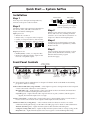
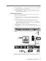
Quick Start — System 5ccr Plus
Installation
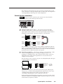
Step 1
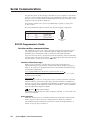
Unbalanced Output
Turn off power to the input and output devices,
and remove the power cords from them.
CAUTION
Step 2
Attach the switcher to the input and output devices.
See “Power, video, and audio connections” in
chapter 2 for details and diagrams.
Input options are:
• RGB for PC 1 and PC 2
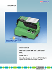
• RGB, S-video, or composite video for Input 3
• S-video or composite video for Vid 1 & Vid 2
• Balanced/unbalanced stereo audio for all inputs
Tip
Sleeve
Tip
Sleeve
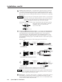
With AC power still removed, connect control
devices and accessories, including an RS-232
controller. See “Control device connections” in
chapter 2 for details and wiring diagrams.
Step 4
Connect power cords and apply power to the
switcher, the input and output devices, and the
RS-232 controller.
600 ohms
Unbalanced Input
Balanced Input
Balanced Input
(high impedance:
over 10 kohms)
(high impedance)
(600 ohms)
Connect sleeve to ground (Gnd).
Connecting the sleeve to a negative
terminal will damage the circuits.
Step 3
Tip
Ring
Sleeve (s)
Tip
Ring
Tip
Ring
Sleeve (s)
Tip
Ring
Balanced Output
Tip
Ring
Sleeve (s)
Tip
Ring
Tip
See Caution
Sleeve (s)
Tip
See Caution
Step 5
Output options are:
• RGBHV, RGBS, S-video, or composite video
Set up (configure) the System 5cr Plus via front
panel controls, RS-232 SIS commands, or the
Windows-based control program.
(See the next page.)
• Balanced or unbalanced audio output via the
line level or amplified outputs.
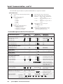
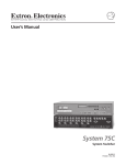
Front Panel Controls
S-video or composite
video inputs with audio
SYSTEM 5
ROOM
Power
LED
POWER
DISPLAY
MUTE
AUDIO
MODE
Room
Display (projector)
control
controls
(for Room/ for setting and sending
relay port) learned IR commands
(once the button is
See pages
programmed)
2-6 and 4-7.
PC1
PC2
PC
VID1
INPUT 3
VID2
VID
VID
VID
Y/C
Y/C
Y/C
RGB computer
video inputs
with audio
AUDIO
MAX.
CLIP
MIN. VOLUME
Audio volume
master control
or control for
amplified output
TX
CONFIG
RETRY
PC 1 (input 1)
RGB computer
video input with
audio
Plus
IR
PC1 INPUT
COMPUTER
RX LEARN
IR
IR receiver
control
and IR
LEDs
learning
ports
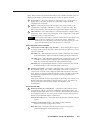
See “Front Panel Controls and Indicators” in chapter 3 for details. Refer to the Windows-based help
program for details on settings.
Audio indicator LEDs (Max, Clip, and Min) — These light in response to changes made via the front panel
volume control knob or RS-232 or control software.
Max/Min LEDs (red) – Light when the volume control knob reaches its maximum/minimum limit.
They do not indicate anything about the audio level.
Clip LED (green) – Lights when the audio output level starts to peak (overdrive) and the signal is
clipped, often when the input level is too high.
Volume control knob — Adjusts audio volume (audio gain) for the amplified output. It can be used as a
master volume control for both audio outputs if all the inputs have the same level.
IR function LEDs (Tx, Config, Retry) — These indicate stand-alone functions and also are used in
combinations during IR learning. See the LED codes table (page 3-7) for details on LED combinations.
Transmit (Tx) LED (green) – Lights when the System 5cr Plus transmits infrared signals.
Configure (Config) LED (amber) – Lights steadily when the System 5cr Plus is in setup (config.) mode.
Retry LED (red) – Lights when the System 5 does not recognize a command during IR learning.
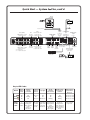
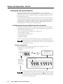
Quick Start — System 5ccr Plus, cont’d
SCP 100P
Control Panel
4
Mute
Volume
Audio
Mode
Room
Display
Mute
Input Selection
2
3
IR 401
System 5cr Plus Remote
Control Functions
Display
Power
1
5
IR 401 Remote
ROOM
POWER
MUTE
MODE
VOLUME
MAX.
CLIP
MIN.
PC1
PC2
INPUT 3
VID1
VID2
Optional
IR Broadcaster
or
SCP 100P
IR Emitter
To second control pad
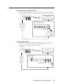
Auxiliary
outputs
Vid 1
PC 2
PC 2 (input 2)
bal./unbal. audio and
• S-video input or
bal./unbal.
audio input • composite video input
RGBHV, RGBS, or RGsB
computer video input
100-240V
1.3A
R
G
R
PC 2
INPUT 3
G/Y
B/C
B
H/HV
V
H/HV
L
L
V
R
R
V/Y
VID 1
VID 2
V/Y
C
C
L
L
RGBHV / RGBS
output
R
R
R
I
N
P
U
T
S
O
U
T
P
U
T
S
G
Y
B
C
VID
H/HV
V
AUX 1
Input 3
Vid 2
bal./unbal.
audio input
bal./unbal. audio and
• S-video input or
• composite video input
Input 3 (configurable)
• RGBHV, RGBS, or RGsB
computer video input
or • S-video input
or • composite video input
for IR Emitter or
IR Broadcaster
AUX 2
RELAY
LiNE OUT
L
R
Amplified audio
output
L/+, R/RS-232
AMPLIFIED OUT
COMM.
A
B
C
D
E
L
L
R
R
DISPLAY PWR
SENSOR
VID
50/60 Hz
Communication
port
for optional
SCP 100P
keypads
RS-232
S-video Composite Line level Room/relay port
control port
(Y/C)
audio
video
for room controls
output
output
output
Power sensor port
bal./unbal.
for optional display
power sensor
Lighting Shades/drapes
Room Control
LCD Projector
Power Sensor
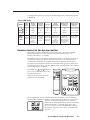
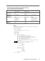
Key to LED Codes
Status
TX
CONFIG
RETRY
What
to do
next
Ready to
learn IR
commands
Command
has been
learned
Try again
No IR
subcarrier
was received
Off
Off
Blinks once
Off
On
Blinking
On
On
Off
Off
Blinks once
Configure
a
System 5
feature.
Aim projector's
remote at IR
learning port.
Press a button
for the
function on
the remote.
Continue
with setup
or exit to
normal
mode.
Setup
mode is
active
Ready to learn
the power-off
command
Timeout exit to
normal mode
will occur
Off
Off
Blinks for 5 seconds
On
Blinking
Blinks for 5 seconds
Blinks once
Blinking
Blinking
Blinks for 5 seconds
Press the
same button
again on the
projector's
IR remote.
Press the
same System 5
Display button
again,
and press the
IR remote's
button again.
Double-click the
System 5's
Display Power
button, then press
the power button
on the projector's
remote.
Press any
button to stay in
setup mode.
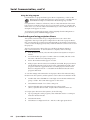
Setup (Configuration) Procedure
Normal Mode
ROOM
POWER
DISPLAY
MUTE
MODE
At any point after entering
the setup mode, you can
Setup
(Config)
Mode
TX
CONFIG
RETRY
Configure
any of the features described here,
in any order,
or
Wait 20 seconds to time out to Normal mode.
CONFIG LED lights
Press and hold all 3 DISPLAY buttons
together for 2 seconds.
Press the ROOM button twice.
The ROOM LED blinks for 8 seconds.
During that time, do one of the following:
Press and hold
all 3 DISPLAY buttons
together for 2 seconds
to return to Normal Mode.
or
Wait 20 seconds
for the System 5 to
time out to Normal Mode.
Clearing button
configurations
ROOM
DISPLAY
MUTE
POWER
PC1
MODE
PC2
PC
INPUT3
VID1
VID2
VID
VID
VID
Y/C
Y/C
Y/C
Press any desired front panel button to clear & reset only that button's IR configuration.
or
Press all 3 DISPLAY buttons at the same time for 2 seconds to clear and reset all System 5 settings.
With an active audio signal present,
press an input's button twice in quick succession
to adjust its audio input. The input's LED blinks.
Setting
audio input
attenuation
levels
AUDIO
PC1
PC2
PC
INPUT3
VID1
VID2
VID
VID
VID
Y/C
Y/C
Y/C
MAX.
CLIP
MIN. VOLUME
Turn VOLUME knob up (clockwise)
until CLIP LED is on or blinking fast.
Turn VOLUME knob
down (counter-clockwise)
until the CLIP LED is off or
blinks occasionally as
the level peaks.
Press the input's
button once to
save. Repeat for
each audio input.
Press and hold the ROOM button
while setting video formats.
ROOM
Selecting
video formats
POWER
DISPLAY
MUTE
MODE
PC1
PC2
PC
INPUT3
VID
Y/C
Y/C
Y/C
TX
CONFIG
RETRY
CONFIG LED blinks
Point the projector's IR remote
control at the System 5's
IR LEARN port and firmly press
the desired button on the remote.
PLUS
SYSTEM 5
AUDIO
Initiating
IR learning
PC1 INPUT
COMPUTER
Release
the ROOM
button
Repeat for VID1 and VID2
TX
CONFIG
RETRY
CONFIG LED lights steadly while
TX & RETRY LEDs flash to indicate
that the signal has been learned.
TX
CONFIG
RETRY
For POWER button configuration,
if the TX LED is off and both the
CONFIG and RETRY LEDs blink,
the System 5 is ready to
learn the power-off signal.
or
IR
TX
CONFIG
RETRY
VID2
VID
Press INPUT3 to toggle between
video formats for that input (an LED
lights to indicate the selected format).
Press the
DISPLAY POWER,
MUTE, or MODE
button & hold it
for 2 seconds.
VID1
VID
RX LEARN
Press the System 5's POWER
button twice in quick succession,
then aim the remote and press the
IR remote's power button again.
or
1
2
3
4
5
6
7
8
9
0
TX
CONFIG
RETRY
If the TX LED is off and the
RETRY LED blinks once, press the
POWER, MUTE, or MODE button
and the IR remote's button again.
Repeat all steps for each
DISPLAY button to be learned.
Quick Start — System 5ccr Plus, cont’d
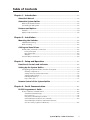
Table of Contents
Chapter 1 • Introduction ....................................................................................................... 1-1
About this Manual ............................................................................................................. 1-2
About the System 5ccr Plus ............................................................................................... 1-2
What is the System 5cr Plus? .............................................................................................. 1-2
Controlling an A/V system ................................................................................................. 1-2
Features and Options ........................................................................................................ 1-4
Features .............................................................................................................................. 1-4
Options and accessories ..................................................................................................... 1-5
Chapter 2 • Installation .......................................................................................................... 2-1
Mounting the Switcher .................................................................................................... 2-2
Table/wall mounting .......................................................................................................... 2-2
Rack mounting ................................................................................................................... 2-2
Cabling and Panel Views ................................................................................................. 2-2
Power, video, and audio connections ............................................................................... 2-2
Front panel inputs ........................................................................................................ 2-2
Rear panel inputs ......................................................................................................... 2-3
Outputs ................................................................................................................................ 2-4
Control device connections ............................................................................................... 2-5
Chapter 3 • Setup and Operation .................................................................................... 3-1
Front Panel Controls and Indicators .......................................................................... 3-2
Setting Up the System 5ccr Plus ..................................................................................... 3-4
Configuring the System 5cr Plus from the front panel ..................................................... 3-4
Clearing configurations ...................................................................................................... 3-4
Setting audio input attenuation levels .............................................................................. 3-5
Selecting video formats ...................................................................................................... 3-5
Initiating IR learning ........................................................................................................... 3-6
Key to LED codes ................................................................................................................. 3-7
Remote Control of the System 5ccr Plus .................................................................... 3-7
Chapter 4 • Serial Communication ................................................................................. 4-1
RS-232 Programmer’s Guide .......................................................................................... 4-2
Host-to-switcher communications .................................................................................... 4-2
Switcher-initiated messages ............................................................................................... 4-2
Error responses .................................................................................................................... 4-2
Using the command/response tables ................................................................................. 4-3
Command/response table for SIS commands .................................................................... 4-4
Command/response table for advanced instructions
(for the control program for Windows) ............................................................................ 4-5
System 5ccr Plus • Table of Contents
i
Table of Contents, cont’d
Control Software for Windows .................................................................................... 4-6
Installing the software ...................................................................................................... 4-6
Using the software ............................................................................................................ 4-6
Using the control program ................................................................................................. 4-6
Saving and restoring configurations ................................................................................. 4-7
Using the help program ..................................................................................................... 4-8
Downloading and using projector drivers ........................................................................ 4-8
Appendix A • Appendix ........................................................................................................ A-1
Specifications ....................................................................................................................... A-2
Part Numbers and Accessories .................................................................................... A-4
Included parts ................................................................................................................... A-4
Accessories ......................................................................................................................... A-4
Firmware Upgrade Installation ................................................................................... A-5
Glossary .................................................................................................................................. A-6
68-498-01 Rev. D
Printed in the USA
02 02
ii
System 5ccr Plus • Table of Contents
System 5ccr Plus
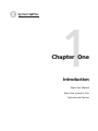
1
Chapter One
Introduction
About this Manual
About the System 5cr Plus
Features and Options
Introduction, cont’d
Introduction
About this Manual
This manual discusses how to install, operate and configure the Extron
System 5cr Plus switcher and how to operate the IR 401 infrared remote control that
is included with the System 5cr Plus. For information on installing and operating
related accessories, see the user’s guides for the following products: Extron’s
Current/Display Power Sensor (part #68-391-01), IR Broadcaster (part #68-392-02),
and SCP 100P Control Pad (part #68-390-01).
Throughout this manual the terms “System 5” and “System 5cr Plus” are used
interchangeably to refer to the same product.
cr Plus
About the System 5cr
What is the System 5cr
cr Plus?
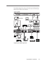
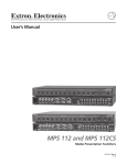
The System 5 switcher provides central control for small audio/video (A/V)
installations. It offers video and audio switching, room control, and projector
control. Each of these functions can be controlled by the front panel, by a hardwired control pad (the SCP 100P), and by infrared remote control (the IR 401). The
switcher can be used to control video and audio input settings; display functions
such as power, video mute, and video modes; and room functions, such as
lowering or raising a display screen or powering lights on or off. The System 5 also
features the ability to “learn” infrared projector control commands.
The System 5 accepts two computer-video (RGB) inputs, two composite video or
S-video inputs, and one RGB or composite video or S-video input, for a total of five
video inputs. It also accepts five line-level stereo audio inputs.
The System 5 outputs computer video (RGBHV/RGBS/RGsB), or NTSC/PAL
S-video or composite video to one display device. The System 5 also offers one line
level (line out) and one amplified stereo audio output. Rear panel ports allow
connection of the IR Emitter and/or the optional IR Broadcaster or hard-wired
projector remote control, and addition of an optional display power sensor, remote
control keypads and an RS-232 controller.
Controlling an A/V system
The System 5 and other devices can be controlled using one or more of these items:
• The front panel controls.
• A computer, a touch screen panel, or any other device that can send and receive
serial communications through the RS-232 port. Extron’s Simple Instruction
Set™ (SIS™) is a set of simple keystroke commands that can be used with
any such devices, and Extron’s control software for Windows provides a
graphical interface for controlling the switcher from a computer.
• Optional control pads (the SCP 100P) that can be mounted in a wall or podium
and hard-wired to the System 5. Each SCP 100P replicates the front panel
functions, and it can receive IR signals and pass them to the System 5.
• The IR 401 remote control, which can also perform all of the front panel
functions.
For the System 5 to control a projector, it must be programmed. The System 5 can
program itself by learning projector IR commands, or Extron’s IR library of
commands can be loaded into the System 5’s memory. The IR library and the
latest control software are available on the Extron web site at
http://www.extron.com.
The System 5 learns new projector control commands from infrared (IR) signals it
receives via its front panel IR ports. These commands are added to the panel
functions. When a function is selected, the System 5 transmits the learned IR signal
to the projector through the IR Emitter or the optional IR Broadcaster.
1-2
cr Plus • Introduction
System 5cr
IR commands for the projector can be associated with each of the Display buttons
(Power, Mute, and Mode) on the front panel, as well as with each of the five input
buttons (PC 1, PC 2, Input 3, Vid 1, and Vid 2).
System 5
Plus
SYSTEM 5
ROOM
POWER
DISPLAY
MUTE
AUDIO
MODE
PC1
PC2
VID
VID1
INPUT 3
AUDIO
VID2
Y/C
VID
VID
PC
Y/C
Y/C
Plus
IR
PC1 INPUT
COMPUTER
MAX.
CLIP
MIN. VOLUME
TX
CONFIG
RETRY
RX LEARN
Front
Control Functions
Display
Power
Audio
Display
Mute
Mute
Mode
Volume
Room
1
IR 401
Remote
SVGA Compatible
Computer w/ Audio
Input Selection
2
3
4
5
IR 401
System 5cr Plus Remote
Laptop Computer
IR REMOTE
4
Mute
Volume
Audio
Mode
Room
Display
Mute
Input Selection
2
3
Control Functions
Display
Power
5
1
IR 401
System 5cr Plus Remote
INPUT
IR 401 Remote
HIGH Z
AUDIO
DISPLAY
ROOM
POWER
MUTE
MODE
VOLUME
MAX.
CLIP
75 Ohm
MIN.
PC1
LCD Projector
VCR
PC2
INPUT 3
VID1
VID2
SCP 100P
SCP 100P
Control Pad
RGB 406
Interface
Composite
100-240V
1.3A
R
R
G
G/Y
B
PC 2
INPUT 3
B/C
H/HV
H/HV
V
V
L
L
R
R
V/Y
VID 1
VID 2
V/Y
C
C
L
L
To Second Control Pad
R
R
R
O
U
T
P
U
T
S
I
N
P
U
T
S
VID
50/60 Hz
Rear
Y
G
C
B
VID
H/HV
V
AUX 1
AUX 2
RELAY
RS-232
AMPLIFIED OUT
COMM.
LINE OUT
L
R
L
L
R
R
DISPLAY PWR
SENSOR
S-video
Audio
Computer
Interface
SVGA Compatible Computer
or
VCR
Powered Speakers
or
Document Camera
Cassette Recorder
Speakers
A typical System 5cr Plus application
cr Plus • Introduction
System 5cr
1-3
Introduction, cont’d
Features and Options
Features
250 MHz (-3dB) video bandwidth
Five video inputs —
• 2 RGBHV/RGBS/RGsB computer video inputs — A VGA 15-pin HD front
panel connector (PC 1) allows direct connection of a laptop computer, and
one set of five BNC rear panel connectors (PC 2) accepts inputs via an
interface.
• 1 RGBHV/RGBS/RGsB computer video or S-video or composite video
input — A set of five BNC rear panel connectors (Input 3) accepts RGB input
via an interface, or it can be configured to accept either S-video or composite
video input instead of RGB input.
• 2 S-video or composite video inputs — Inputs Vid 1 and Vid 2 each have
two rear-panel BNC connectors.
One video output — A total of eight rear-panel BNC connectors provide
connections for RGB, S-video, or composite video (NTSC/PAL) output. Only
one output (RGB or S-video or composite video) is active at any one time,
even if all three sets of BNCs are connected to the projector.
Five balanced/unbalanced stereo audio inputs — One front panel mini stereo jack
and four rear panel captive screw ports accept audio inputs. Each input’s
levels can be individually preset, then adjusted by the master volume control.
Two stereo audio outputs —
• Line level (line out) output (balanced or unbalanced) via a captive screw
terminal can be treated as a pre-amp. The output can be adjusted using the
master volume control, or it can be set via RS-232 control to provide a fixed
output level.
• Amplified output (unbalanced) of 24 watts (12 watts per channel with a
4 ohm load) or 12 watts ( 6 watts per channel with an 8 ohm load) is available
for non-powered speakers via spring-loaded captive terminals. The master
volume control adjusts the output level.
Audio breakaway — Audio and video can be switched separately via RS-232
control by using the Windows-based control program.
Three control methods — A computer or other RS-232 control device, the IR 401
remote control, or an SCP remote keypad can all be used to control the
switcher.
RS-232 programming — The System 5 can be programmed using an RS-232
control device and SIS or Extron’s control software for Windows.
Room control — The System 5 provides a relay for controlling a variety of items
such as lighting, window coverings, or display screens.
Projector control — The System 5 can control the projector’s display power, video
mute, and mode functions.
IR command learning — The switcher can learn new IR commands from signals
received through the front panel or downloaded from Extron’s command
library. Learned commands are output through the IR Emitter or IR
Broadcaster.
IR Emitter — The included IR Emitter transmits learned commands and incoming
infrared control signals to devices nearby.
Memory — All IR commands are stored in memory.
1-4
cr Plus • Introduction
System 5cr
Triple-Action Switching™ — With this method, a blank screen is displayed while
the System 5 switches between RGB inputs.
Versatile mounting options — The System 5 can be rack mounted, or it can be
mounted under a desk or table, or on (against) a wall or the side of a desk.
Mounting brackets are included.
Options and accessories
The System 5’s optional equipment expands a user’s ability to control system
devices. Optional equipment includes:
• Display power sensor — This sensor (part #60-271-01) detects whether the
projector’s power is on or off in order to keep the System 5 and the projector
in sync.
• Remote control keypad — Up to two hard-wired remote keypads, such as
Extron’s SCP 100P control panel (part #60-331-01, -02 or -03) can be
connected via rear panel auxiliary ports. This accessory not only duplicates
the functions of the System 5’s front panel, it also receives IR signals from the
IR 401 and transmits them to the System 5.
• IR broadcast device — A device such as Extron’s IR Broadcaster (part
#60-272-01) has a greater range than the IR Emitter and transmits signals over
a wide area.
Plus
SYSTEM 5
ROOM
POWER
DISPLAY
MUTE
AUDIO
MODE
PC1
PC2
PC
INPUT 3
VID1
AUDIO
VID2
VID
VID
VID
Y/C
Y/C
Y/C
IR
PC1 INPUT
COMPUTER
MAX.
CLIP
MIN. VOLUME
TX
CONFIG
RETRY
RX LEARN
Front
Control Functions
Display
Power
Audio
Display
Mute
Mute
Mode
Volume
Room
1
IR 401
Remote
Input Selection
2
3
4
5
IR 401
System 5cr Plus Remote
4
Mute
Volume
Audio
Mode
Room
Display
Mute
Input Selection
2
3
Control Functions
Display
Power
1
5
IR 401
System 5cr Plus Remote
LIGHTING
IR 401 Remote
ROOM
POWER
MUTE
MODE
VOLUME
MAX.
CLIP
MIN.
PC1
PC2
INPUT 3
VID1
VID2
Optional
IR Broadcaster
SHADES/DRAPES
Room Control
or
SCP 100P
SCP 100P
Control Panel
IR Emitter
To Second Control Pad
100-240V
1.3A
50/60 Hz
R
G
B
R
PC 2
INPUT 3
G/Y
B/C
H/HV
H/HV
V
V
L
L
R
R
V/Y
VID 1
VID 2
V/Y
C
C
L
L
R
R
R
Y
G
C
B
VID
H/HV
V
AUX 1
AUX 2
RELAY
RS-232
AMPLIFIED OUT
COMM.
LINE OUT
L
R
L
L
R
R
DISPLAY PWR
SENSOR
VID
Rear
LCD Projector
Power Sensor
RS-232 Control
The System 5cr Plus (front and rear) with its options and accessories
cr Plus • Introduction
System 5cr
1-5
Introduction, cont’d
1-6
cr Plus • Introduction
System 5cr
System 5ccr Plus
2
Chapter Two
Installation
Mounting the Switcher
Cabling and Panel Views
Installation, cont’d
Installation
Mounting the Switcher
The System 5cr Plus comes with two sets of mounting brackets. One set is for
mounting the switcher under a table or on (against) a wall, and the other set is for
rack-mounting.
Table/wall mounting
The table/wall-mounting brackets extend approximately 1/4” (6.3 mm) above the
top surface of the System 5 enclosure, as shown below. This design allows for an
air space between the enclosure and the surface on which it is mounted. Attach the
table/wall-mounting brackets to the switcher with the provided machine screws,
as shown below.
Mounting Screws
(2 Places)
Each Side
Rack-mount
Bracket
-232
RS
AM
or
AU
X1
AU
X2
RE
LA
Y
CO
MM
PL
IFIE
D OU
T
L
R
.
L
R
V
R
Y PW
LA NSOR
DISP SE
V
H/H
B
G
R
T
OU
MP
EA R
PR L
VID
C
Y
R
L
C
R
V/Y
R
L
V
#8 Screw (4 Plcs)
Each Side
Table/
Wall-mount
Bracket
/60
50
C
L
V
V
H/H
G
2
PC 3
B
PC
R
G
A
1.3
V
40
0-2
10
1
VID 2
VID
V/Y
R
V
H/H
B
L
R
Hz
Mounting the System 5cr Plus
Rack mounting
The switcher can also be rack mounted. Attach the rack-mounting brackets to the
switcher with the provided machine screws, as shown above, then fasten the
switcher to the rack using the supplied machine screws.
Cabling and Panel Views
Power, video, and audio connections
With the exception of input PC 1 on the front panel, all input and output connectors
are on the rear panel. The LEDs adjacent to the corresponding buttons on the front
panel light when each input is active.
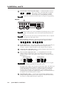
Front panel inputs
The PC 1 input on the front panel accepts computer video (RGBHV, RGBS or RGsB)
through a VGA 15-pin HD connector, and
unbalanced stereo audio through a 3.5 mm mini
stereo jack, as shown in the illustration at left.
SYSTEM 5
AUDIO
IR
PC1 INPUT
COMPUTER
TX
CONFIG
RETRY
2-2
System 5ccr Plus • Installation
RX LEARN
Plus
To wire the PC 1 audio input plug, follow the wiring diagram shown below.
Tip (+)
Sleeve (GND)
Ring (R, -)
Tip (L, +)
Sleeve (GND)
PC1 audio input plug wiring
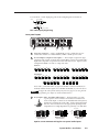
Rear panel inputs
100-240V
1.3A
R
G
R
PC 2
INPUT 3
G/Y
B/C
B
H/HV
H/HV
V
L
R
L
V
V/Y
VID 1
VID 2
V/Y
R
C
C
L
R
L
R
I
N
P
U
T
S
VID
50/60 Hz
1
2
3
4
3
1
AC power connector — Plug a standard IEC power cord into this port to
connect the switcher to a 100 to 240VAC, 50 Hz or 60 Hz power source.
2
PC 2 and Input 3 computer video inputs — These inputs accept VGA-type
computer-video signals, and each has 5 female BNC connectors for RGB video
input with composite or separate horizontal and vertical sync. Input 3 can be
configured for RGB or S-video or composite video.
For PC 2:
R
G
B
H/HV
R
V
G
RGBHV
B
H/HV
R
V
RGBS
G
B
H/HV
V
RGsB (Sync on Green)
For Input 3:
R
G/Y
B/C
H/HV
R
V
G/Y
VID
B/C
H/HV
R
V
G/Y
VID
RGBHV
RGBS
R
G/Y
B/C
H/HV
B/C
H/HV
V
VID
V
RGsB (Sync on Green)
R
VID
G/Y
B/C
H/HV
V
VID
S-video (Y/C)
Composite Video
For S-video, connect the luma (Y) signal to the BNC connector marked G/Y
and Vid, and the chroma signal (C) to the BNC marked B/C, as shown above.
Configure the video format via the front panel (see page 3-5) or using RS-232
programming (see chapter 4, “Serial Communication”).
3
PC 2, Input 3, Vid 1, and Vid 2 audio inputs — Each input has a 3.5 mm,
5-pole captive screw connector for balanced or unbalanced
stereo audio input. Connectors are included with each System 5,
but the user supplies the audio cable. See the wiring diagrams
below to wire a connector for the appropriate input type and
impedance level. High impedance is generally over 800 ohms.
600 ohms
Tip
Ring
Sleeve (s)
Tip
Ring
Tip
Sleeve
Tip
Sleeve
Tip
Ring
Sleeve (s)
Tip
Ring
600 ohms
Unbalanced Input
Balanced Input
Balanced Input
(high impedance)
(high impedance)
(600 ohms)
Captive screw connector wiring for rear panel audio inputs
System 5ccr Plus • Installation
2-3
Installation, cont’d
4
Vid 1 and Vid 2 composite/S-video inputs — Connect the cables as shown
V/Y
C
V/Y
C
here. For S-video, connect the luma (Y) signal to
the left BNC connector, marked V/Y, and the
S-video
Composite video
chroma signal (C) to the right BNC, marked C.
Configure the video format via the front panel or using RS-232 programming.
Outputs
1
R
O
U
T
P
U
T
S
G
C
Y
H/HV
B
V
AUX 1
AUX 2
RELAY
A
B
C
D
E
LINE OUT
L
R
VID
RS-232
AMPLIFIED OUT
COMM.
L
L
R
R
DISPLAY PWR
SENSOR
2
3
4
5
All three outputs can be connected simultaneously, although only one is active
at a time. The output that is active is determined by the format of the active
input.
The LED next to the connector(s) for each output (RGB, S-video, or composite
video) lights when that output is active.
1
RGB output BNC connectors — Connect coaxial cables from the display
device to these BNCs for one RGBHV or RGBS video output as follows:
R
G
B
H/HV
V
RGBHV
R
G
B
H/HV
V
RGBS
2
S-video output (Y, C) — For S-video output, connect the cable for the luma (Y)
signal to the Y connector, and the cable for chroma (C) signal to the C
connector. A BNC-to-4-pin mini DIN (S-video) adapter may be required.
3
Composite video output BNC (Vid) — Connect the display device here, via a
coaxial cable, for composite video output.
4
Line level audio output (Line Out) — For unamplified, line level audio
output, connect an audio device, such as an audio recorder or powered
speakers, to this 3.5 mm, 5-pole captive screw connector. Follow the wiring
diagram below.
Unbalanced Output
CAUTION
Balanced Output
Tip
Ring
Sleeve (s)
Tip
Ring
Tip
See Caution
Sleeve (s)
Tip
See Caution
Connect the sleeve to ground (Gnd). Connecting the sleeve to a negative
(-) terminal will damage the audio output circuits.
The signal at this output comes from the selected audio input. The audio level
from the Line Out output can either be variable (in response to front panel
volume adjustment), or it can be set to a fixed level that is not affected by
changes to the front panel volume adjustment. Use the Windows-based
control program to change the output mode setting or to set audio breakaway.
See chapter 4, Serial Communication, for details.
5
2-4
Amplified audio output — Connect unpowered speakers directly to these
spring-loaded captive terminals for stereo output. Connect the left channels
to positive/L, and the right channels to negative/R.
System 5ccr Plus • Installation
This output provides 24 watts of power (12 watts per channel with a 4 ohm
load) or 12 watts ( 6 watts per channel with an 8 ohm load). The output level
varies depending on the front panel volume adjustment.
Control device connections
Captive screw and 3.5 mm stereo jack connectors are included with the
System 5, but the installer provides the cables.
AUX 1
AUX 2
RS-232
AMPLIFIED OUT
RELAY COMM.
A
B
C
D
E
L
L
R
R
DISPLAY PWR
SENSOR
1
1
2
3
4
5
Auxiliary outputs (Aux 1, Aux 2) — One optional external SCP 100P,
SCP 250, or SCP/AAP A control panel can be connected to each of these
5-pole captive screw connectors. The control panel replicates the switcher’s
front panel control features. Wire the connectors as shown below.
AUX
System 5
AUX port
A
B
C
D
E
IR signals in (violet)
Gnd (black)
Comm signal (white)
Gnd (drain)
+12V (red)
Port on
SCP
circuit
board
A
B
C
D
E
IR signals in (violet)
Gnd (black)
Comm signal (white)
Gnd (drain)
+12V (red)
The Aux 1 and Aux 2 ports provide a total of 500 mA, split between the two
ports, so each port provides 250 mA of current. Refer to the SCP 100P User’s
Manual (part #68-390-01) or the SCP/AAP A, SCP 200, SCP 250 User’s Manual
(part #68-511-01) for details about the control panels.
Room/relay port (Relay) — This allows control of “room” functions – items
such as room lighting, window coverings, and display screens – via
momentary or latching contact. These contacts can be used to control any
equipment as long as the contact specifications of a total of 24 volts at
1 ampere are not exceeded.
This port has two sets of contacts: one pair is closed by default, the other pair
is open by default, as shown below.
Normally closed (2)
Normally closed (1)
Normally open (2)
Normally open (1)
System 5
RELAY port
2
Normally closed (2)
Normally closed (1)
Normally open (2)
Normally open (1)
Not used
To / from
room control
equipment
Not
used
When the room function is active, the closed contacts open, and the open
contacts close. Contacts can be programmed to operate in one of two ways:
• latching (brief contact) (press to turn on, press to turn off), or
• momentary (timed) (press to turn on, timeout to turn off).
In the timed mode the default timeout period is 1/8 second. Use the control
software for Windows to change the length of the timeout period. See Serial
Communications, chapter 4, for details.
System 5ccr Plus • Installation
2-5
Installation, cont’d
3
Display power sensor port — This mini stereo-style jack allows connection
of an optional display power (current) sensor (Extron part #60-271-01). The
power sensor is used to keep the projector and the System 5 in sync. Refer to
the Power Sensor User’s Guide, part #68-391-01, for information on operating
the sensor.
The power sensor port on the System 5 supplies +12VDC. To avoid electric
shock when connecting the cable from the power sensor into the System 5,
always connect the stereo jack at one end of the cable to the power sensor
unit before plugging the jack at the other end into the System 5.
The wiring connections are the same on both ends of the cable that connects
the power sensor to the System 5. Wire the
Tip (+12V)
Sleeve (GND)
included connector as shown at left.
Use a 3-wire cable.
Ring (signal)
Tip (+12V)
Sleeve (GND)
4
Projector communications port (Comm) — Connect the included IR Emitter
or optional IR Broadcaster via this captive screw connector to send learned/
uploaded IR signals (which differ from IR 401 remote control signals) to
control the projector. The signals from the optional IR Broadcaster cover a
wider area and greater distance than do those from the emitter, so it can be
placed further from the projector. The IR Broadcaster is often used to replace
the IR Emitter.
Wire the connector using one of the wiring options shown below.
COMM
A
B
C
D
E
4A
System 5
Comm port
Reserved/not used
Gnd*
Carrier & signal
Gnd*
+12V
White striped wire only
IR Emitter
*Either the second or the fourth pole can be used for ground.
For IR Emitter only
Sleeve (Gnd)
COMM
A
B
C
D
E
4B
Signal
Gnd
Carrier & signal
Gnd
+12V
Tip (signal)
To projector's
wired remote
control
White striped wire
System 5
Comm port
IR Emitter
For IR Emitter and/or wired projector remote
COMM
A
B
C
D
E
4C
System 5
Comm port
For IR Broadcaster
Reserved/not used
Gnd
Carrier & signal
Gnd
+12V
Sleeve (Gnd)
Ring (signal)
Tip (+12V)
To the
IR Broadcaster
(60-272-02)
Tip (+12V)
Sleeve (Gnd)
Projector communications (Comm) port connections
For some projectors the emitter must be used together with the IR Broadcaster.
Refer to the IR Broadcaster User’s Guide (part #68-392-02) or contact an
Extron support representative for details.
5
2-6
RS-232 port — Connect a device such as a computer or touch panel control to
the System 5 via this 9-pin D connector for serial RS-232 control. See the
Serial Communications chapter for information on how to install and use the
control software and the SIS commands.
System 5ccr Plus • Installation
System 5ccr Plus
3
Chapter Three
Operation
Front Panel Controls and Indicators
Setting Up the System 5cr Plus
Remote Control of the System 5cr Plus
Setup and
Operation,
cont’d
Setup
and
Operation
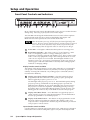
Front Panel Controls and Indicators
SYSTEM 5
ROOM
POWER
DISPLAY
MUTE
AUDIO
MODE
PC1
PC2
PC
VID
Y/C
1
2
3
4
5
6
VID1
INPUT 3
7
AUDIO
VID2
VID
VID
Y/C
Y/C
8
MAX.
CLIP
MIN. VOLUME
9
10
Plus
IR
PC1 INPUT
COMPUTER
TX
CONFIG
RETRY
RX LEARN
11
Most of the front panel controls described in this section also have another function
during setup. See Setting Up the System 5cr Plus in this chapter.
The SCP 100P remote keypad and the Windows-based control software replicate
items 2 through 10 shown above, which are described in this chapter. The
IR 401 remote control replicates the controls without the LEDs.
When the System 5 powers up, all of the front panel LEDs light briefly, then
turn off. The Power LED (1) lights and stays on until the System 5 is powered
down. The LED for the last selected input, and the rear panel LED for the
selected input format will light and remain on until the input is changed.
1
Power LED — This lights to indicate that the System 5 is receiving power.
2
Room button and LED — This allows control of “room” functions – items
such as room lighting, window coverings, and display screens – via
momentary or latching contact through the Relay port. These contacts can be
used to control any equipment as long as the contact specifications of a total
of 24 volts at 1 ampere are not exceeded. The LED lights while the room
function is active (on). See page 2-5 for information on the room/relay port,
and see page 4-7 and refer to the Windows-based System 5cr Help program
for details on changing settings.
Display function controls and LEDs
The settings of the display functions (power, mute, and mode) are customized for
each projector. These buttons function only after they have been programmed,
either by “learning” IR commands or by loading projector commands (drivers)
from the Extron IR library.
3
Display power (Power) button and LED — Once the System 5 has been
programmed with the commands for the specific projector, pressing this
button toggles the projector’s power on or off.
The LED lights when projector power is on. The LED blinks quickly during
projector power-up, and it blinks slowly during projector power-down.
While the LED is blinking, do not send commands to the projector because
the projector is not able to accept them. The blinking periods (power-up/
down delay time) are generated within the System 5, not the projector. The
blinking periods can be set only via the Windows-based control program.
4
Display mute (Mute) button — Press this button to toggle the projector’s
“mute” function (to turn off/on the displayed image) once the Mute button
has been programmed for use with the projector.
5
Display mode (Mode) button — This button can be programmed to switch
the mode of the projector between computer-video (RGB), S-video, and
composite video. It replicates the 1-button (step) mode function provided on
some projectors’ remote controls.
Input selection controls and LEDs
Use these buttons to select the appropriate input source. LEDs next to each button
indicate the format of the incoming video signal. Only the selected input’s LED
3-2
System 5ccr Plus • Setup and Operation
lights. If the System 5 has learned commands, it may send IR commands (such as a
display mode change command) to the projector when an input is selected.
6
PC 1 and PC 2 — Press these buttons to select input 1 (PC 1, front panel) or
input 2 (PC 2, rear panel), respectively. Both inputs accept only RGB
computer-video and audio.
7
Input 3 — This button corresponds to Input 3 (rear panel), which can be
configured to accept audio and RGB, or S-video, or composite video. The
LED corresponding to the selected format lights when Input 3 is selected.
8
Vid 1 and Vid 2 — Press these buttons to select input 4 (Vid 1) or input 5 (Vid 2),
respectively. Both of these rear panel inputs can be configured to accept audio
and either S-video or composite video.
Audio breakaway (the ability to separately switch audio and video signals from
different inputs) is available only via the RS-232 control. While audio
breakaway is active, the flashing LED indicates the input providing the audio
signal, and the steadily lit LED indicates the active video input.
Audio adjustment control and LEDs
9
Audio indicator LEDs (Max, Clip, and Min) — These LEDs light in response
to changes made via the front panel volume control knob or RS-232 or control
software commands.
Max LED (red) – This LED lights when the volume control knob has reached
its maximum limit. It does not indicate anything about the audio level.
Clip LED (green) – This LED lights when the audio output level starts to peak
(overdrive) and the signal is clipped, often when the input level is too
high. It is used mostly during audio input attenuation setup.
Min LED (red) – This LED lights when the volume control knob has reached
its minimum limit. It does not indicate the audio level.
10
Volume control knob — Turn this to adjust the audio volume (audio gain) for
the amplified output. The volume control knob can be used as a master
volume control for both audio outputs if all the audio inputs have the same
level. There is no physical limit to this knob’s rotation. The Min or Max LED
will light briefly when the knob has reached its functional minimum or
maximum limit.
Audio gain/attenuation can be set per input via the front panel controls or via
RS-232 commands or the Windows-based control program. For details, see
Setting Up the System 5cr Plus in this chapter, and chapter 4, Serial
Communication.
Infrared control LEDs
11
IR function LEDs (Tx, Config, Retry) — These three LEDs indicate standalone functions and also are used in combinations during IR learning. For
example, all three LEDs flash at once to indicate a timeout when the System 5
is in configuration mode. See Setting Up the System 5cr Plus in this chapter for
details on when the LEDs light in combination.
Transmit (Tx) LED (green) – This lights while the System 5 transmits infrared
signals.
Configure (Config) LED (amber) – This lights steadily when the
System 5 is in setup (configuration) mode.
Retry LED (red) – This lights when the System 5 does not recognize a
command during the infrared learning process.
System 5ccr Plus • Setup and Operation
3-3
Setup and Operation, cont’d
Setting Up the System 5ccr Plus
The System 5cr Plus must be set up (configured) before it can control other
equipment. Setup can be done from the front panel, or from a computer using the
provided control software. Setup cannot be done via the IR 401 remote control or
the SCP 100P control pad.
Extron provides preset configurations in the form of projector driver files that can
be downloaded from diskette or the Extron website. See “Downloading and using
projector drivers” in chapter 4 for details. Projector drivers assign projector IR
commands to the System 5’s front panel controls so that the display power, mute,
and mode functions can be used to control the projector.
Configuring the System 5ccr Plus from the front panel
The System 5 must be in the setup (config) mode during setup. The Config LED
lights when the setup mode is on. The following configuration procedures can be
performed from within setup mode:
• clear an individual button’s IR function configurations,
• clear all System 5 settings,
• set audio input attenuation levels,
• select video formats,
• initiate IR learning.
See the flowcharts in this section for the specific steps for setting up the System 5.
When there has been no activity for at least 20 seconds, the System 5 times out
from the setup mode to the normal mode, and the Tx, Config, and Retry LEDs
will all flash for 5 seconds.
Clearing configurations
Clearing configuration settings resets them to factory defaults. To clear
configurations, see the flowchart below.
Normal Mode
ROOM
POWER
DISPLAY
MUTE
MODE
Setup
(Config)
Mode
At any point after entering
the Setup mode, you can
TX
CONFIG
RETRY
Configure any feature in any order,
or
Wait 20 seconds to time out to Normal mode.
CONFIG LED lights
Press and hold all 3 DISPLAY buttons
together for 2 seconds.
Press and hold
all 3 DISPLAY buttons
together for 2 seconds
to return to Normal Mode.
Press the ROOM button twice.
The ROOM LED blinks for 8 seconds.
During that time, do one of the following:
or
ROOM
Wait 20 seconds
for the System 5 to
time out to Normal Mode.
POWER
DISPLAY
MUTE
MODE
PC1
PC2
PC
INPUT3
VID1
VID2
VID
VID
VID
Y/C
Y/C
Y/C
Press any desired front panel button to clear & reset only that button's IR configuration.
or
Press all 3 DISPLAY buttons at the same time for 2 seconds to
clear and reset all System 5 settings.
Pressing all three Display buttons clears and resets all configuration settings
to the factory defaults. These settings include Display functions, IR commands,
room settings, video type, RGB delay, power up/down delay, room relay mode,
audio gain, and all other settings.
3-4
System 5ccr Plus • Setup and Operation
Setting audio input attenuation levels
Before setting the audio levels, ensure that all the audio input sources are active
and connected to the System 5. To set the audio levels, see the following flowchart.
ROOM
POWER
DISPLAY
MUTE
Setup
(Config)
Mode
MODE
At any point after entering
the Setup mode, you can
TX
CONFIG
RETRY
Configure any feature in any order,
or
Wait 20 seconds to time out to Normal mode.
CONFIG LED lights
Press and hold all 3 DISPLAY buttons
together for 2 seconds.
With an active audio signal present,
press an input's button twice in quick succession
to adjust its audio input. The input's LED blinks.
Press and hold
all 3 DISPLAY buttons
together for 2 seconds
to return to Normal Mode.
AUDIO
PC1
PC2
INPUT3
VID1
VID2
or
PC
VID
VID
VID
Wait 20 seconds
for the System 5 to
time out to Normal Mode.
Y/C
Y/C
Y/C
MAX.
CLIP
MIN. VOLUME
Turn VOLUME knob up (clockwise)
until CLIP LED is on or blinking fast.
Turn the VOLUME knob down
(counter-clockwise) until
the CLIP LED is off or blinks
occasionally as the level peaks.
Press the input's button once to save.
Repeat for each audio input.
Selecting video formats
Input 3 can be set to accept computer-video (RGB), S-video (Y/C), or composite
video (Vid, V). Vid 1 (input 4) and Vid 2 (input 5) can be set for S-video or
composite video. Select the format as shown below.
Normal Mode
ROOM
POWER
DISPLAY
MUTE
MODE
Setup
(Config)
Mode
At any point after entering
the Setup mode, you can
TX
CONFIG
RETRY
Configure any feature in any order,
or
Wait 20 seconds to time out to Normal mode.
CONFIG LED lights
Press and hold all 3 DISPLAY buttons
together for 2 seconds.
Press and hold
all 3 DISPLAY
buttons together
for 2 seconds
to return to
Normal Mode.
or
Wait 20 seconds
for the System 5
to time out to
Normal Mode.
Press and hold the ROOM button
while setting video formats.
ROOM
POWER
DISPLAY
MUTE
MODE
PC1
PC2
PC
INPUT3
VID1
VID2
VID
VID
VID
Y/C
Y/C
Y/C
Press INPUT3 to toggle between
video formats for that input (an LED
lights to indicate the selected format).
Repeat for
VID1 and VID2
Release
the ROOM
button
System 5ccr Plus • Setup and Operation
3-5
Setup and Operation, cont’d
Initiating IR learning
The System 5 can “learn” control commands from projectors’ remote controls.
IR learning is only necessary if there is no IR driver available for that projector or if
the driver is not complete.
The System 5cr Plus has two portholes on its front panel:
SYSTEM 5
•
one for the IR receiver (Rx), which receives signals
from the IR 401 remote; and
•
one for the IR learning device (Learn), which receives
signals from a projector’s remote control during
IR learning.
Plus
IR
TX
CONFIG
RETRY
RX LEARN
During IR learning you might need to hold the projector’s IR remote control as near
to the System 5 as one-half inch and point the remote directly at the IR learning
(Learn) device. Blocking ambient light from the IR learning device, particularly
from flourescent lights, can also help.
Once the System 5 has been programmed to control the projector, do not
perform the learned projector control functions from the projector or the
projector’s remote control. The System 5 will not know that projector control
commands have been sent by an external device. For example, if a projector is
powered on via the System 5, and then the projector is manually turned off at
the projector’s panel, the System 5 will not know the projector is off, and it will
continue to send video signals and commands to the projector.
Normal Mode
ROOM
POWER
DISPLAY
MUTE
Setup
(Config)
Mode
MODE
At any point after entering
the Setup mode, you can
TX
CONFIG
RETRY
CONFIG LED lights
Configure any feature in any order,
or
Wait 20 seconds to time out to Normal mode.
Press and hold all 3 DISPLAY buttons
together for 2 seconds.
Press and hold
all 3 DISPLAY buttons
together for 2 seconds
to return to Normal Mode.
Press the
DISPLAY POWER,
MUTE, or MODE
button & hold it
for 2 seconds.
TX
CONFIG
RETRY
CONFIG LED blinks
or
Wait 20 seconds
for the System 5 to
time out to Normal Mode.
Point the projector's IR remote
control at the System 5's
IR LEARN port and firmly press
the desired button on the remote.
PC1 INPUT
COMPUTER
CONFIG LED lights steadly
while TX & RETRY LEDs flash to
indicate that the signal was learned.
TX
CONFIG
RETRY
For POWER button configuration,
if the TX LED is off and the
CONFIG and RETRY LEDs both
blink, the System 5 is ready to
learn the power-off signal.
or
PLUS
SYSTEM 5
AUDIO
TX
CONFIG
RETRY
IR
TX
CONFIG
RETRY
RX LEARN
Press the System 5's POWER
button twice in quick succession,
then aim the remote and press the
IR remote's power button again.
or
TX
CONFIG
RETRY
1
2
3
4
5
6
7
8
9
0
If the TX LED is off and the
RETRY LED blinks once, retry by
pressing the POWER, MUTE, or
MODE button and the IR remote's
button again.
Repeat all steps for each
DISPLAY button to be learned.
3-6
System 5ccr Plus • Setup and Operation
To interpret the System 5’s response to the IR learning steps, see the LED response
codes below.
Key to LED Codes
Status
TX
CONFIG
RETRY
What
to do
next
Ready to
learn IR
commands
Command
has been
learned
Try again
No IR
subcarrier
was received
Off
Off
Blinks once
Off
On
Blinking
On
On
Off
Off
Blinks once
Configure
a
System 5
feature.
Aim projector's
remote at IR
learning port.
Press a button
for the
function on
the remote.
Continue
with setup
or exit to
normal
mode.
Setup
mode is
active
Ready to learn
the power-off
command
Timeout exit to
normal mode
will occur
Off
Off
Blinks for 5 seconds
On
Blinking
Blinks for 5 seconds
Blinks once
Blinking
Blinking
Blinks for 5 seconds
Press the
same button
again on the
projector's
IR remote.
Press the
same System 5
Display button
again,
and press the
IR remote's
button again.
Double-click the
System 5's
Display Power
button, then press
the power button
on the projector's
remote.
Press any
button to stay in
setup mode.
Remote Control of the System 5ccr Plus
The System 5 can be controlled by using its front panel controls, the included
IR 401 infrared remote control, optional SCP remote control panels, or an
RS-232 control device or computer.
The IR 401 and SCP control panels replicate the System 5’s front panel controls for
normal mode operations. The RS-232 control device also can send front panel
normal mode commands. A computer using Extron’s Windows-based control
program can perform both normal mode and setup mode operations, and it offers
some functions that are not available with the other control methods. See chapter 4,
Serial Communication, for details.
The IR 401 uses
and
buttons in
place of the volume knob. It also has
an audio mute button.
Control Functions
Display
Power
Audio
Display
Mute
Mute
Mode
Volume
Room
Setup mode operations can not be
performed from the IR 401.
1
Input Selection
2
3
Control Functions
4
Display
Power
Audio
Display
Mute
Mute
Mode
Volume
5
Room
1
Input Selection
2
3
4
IR 401
System 5cr Plus Remote
5
The SCP 100P, SCP/AAP A, and SCP 250 can be mounted in a wall or furniture.
Each includes an IR remote window (corresponding to the IR receiver port on the
System 5) or IR signal pickup device for receiving
commands from the IR 401 remote control and sending
them to the System 5. Infrared signals from other
devices are not passed on to the IR Emitter or the IR
Broadcaster. Up to two SCPs can be connected to the
SCP/ AAP A
System 5.
SHOW ME
POWER
MAX/
MIN
AUDIO
VOLUME
DISPLAY
MUTE
MODE
System 5ccr Plus • Setup and Operation
3-7
Setup and Operation, cont’d
Setup mode operations can not be performed from the SCP control panel(s).
Refer to the SCP 100P User’s Manual
(part #68-390-01) or the SCP/AAP A, SCP 200,
SCP 250 User’s Manual (part #68-511-01) for
details about the control panels.
IR REMOTE
DISPLAY
ROOM
POWER
MUTE
AUDIO
MODE
VOLUME
The SCP 250 can also be used with the
Extron System 7SC switcher. When the
SCP 250 is used with the System 5cr
Plus, the last three buttons are not used.
MAX.
CLIP
MIN.
PC1
PC2
INPUT 3
VID1
VID2
SCP 100P
DISPLAY
POWER
MUTE
AUDIO
MAX/
MODE
IR
MIN
VOLUME
ROOM
1
2
3
4
5
SCP 250
3-8
System 5ccr Plus • Setup and Operation
System 5ccr Plus
4
Chapter Four
Serial Communication
RS-232 Programmer’s Guide
Control Software for Windows
Serial Communication,
cont’d
Serial
Communication
The System 5cr Plus can be remotely controlled via a host computer or other device
(such as a control system) attached to the rear panel RS-232 connector. The control
device (host) can use either Extron’s Simple Instruction Set (SIS) commands or the
graphical control program for Windows.
The System 5 switcher uses a protocol of 9600 baud, 1 stop bit, no parity, and
no flow control.
The rear panel RS-232 9-pin D connector has the following pin assignments:
Pin RS-232 function
2
3
5
Tx
Rx
Gnd
Description
Transmit data
Receive data
Signal ground
9
6
5
1
DB9 Pin Locations
Female
RS-232 Programmer’s Guide
Host-to-switcher communications
SIS commands consist of one or more characters per field. No special characters
are required to begin or end a command sequence. When the System 5cr Plus
determines that a command is valid, it executes the command and sends a
response to the host device. All responses from the switcher to the host end with a
carriage return and a line feed (CR/LF = ), which signals the end of the response
character string. A string is one or more characters.
Switcher-initiated messages
When a local event such as a front panel (or SCP control pad) selection or
adjustment takes place, the System 5 switcher responds by sending a message to
the host. No response is required from the host. The switcher-initiated messages
are listed here (underlined).
(C) Copyright 2000, Extron Electronics, System 5cr Plus, Vx.xx
The System 5 sends the copyright message when it first powers on. Vx.xx is the
firmware version number.
RECONFIG
When a change is made via a front panel control or another operation occurs that
must be written to a new memory block, the System 5 sends the reconfiguration
message. No response is required from the RS-232 host, but the host may request a
new status listing via the request information command (I/i). See the command/
response table in this chapter for details.
C X1
(where X1 is the input number)
The System 5 sends this response when an input is switched. C = both audio and
video were switched.
Error responses
When the switcher receives a valid SIS command, it executes the command and
sends a response to the host device. If the System 5 is unable to execute the
command because the command is invalid or it contains invalid parameters, it
returns an error response to the host.
4-2
System 5ccr Plus • Serial Communication
The error response codes and their descriptions are as follows:
E01 – Invalid input channel number (the number is too large)
E10 – Invalid command
E13 – Invalid value (the number is out of range/too large)
E16 – Unit is busy
E23 – Checksum error.
Using the command/response tables
The command/response tables on the next page list valid command ASCII codes,
the switcher’s responses to the host, and a description of the command’s function
or the results of executing the command. Lower case characters are acceptable in
the command field only where indicated.
ASCII to HEX Conversion Table
•
The ASCII to HEX
conversion table at left is
for use with the
command/response tables.
ASCII to Hex conversion table
System 5ccr Plus • Serial Communication
4-3
Serial Communication, cont’d
The command/response tables use symbols (defined below) to represent variables.
Symbol definitions
= CR/LF (carriage return/line feed) (hex 0D 0A)
X4
= Audio attenuation steps (0 through 100)
= Space
X5
X1
= Input number (0 through 5)
0 = no connection
1 = PC 1
2 = PC 2
3 = Input 3
4 = Vid 1
5 = Vid 2
X6
X2
= 0 = off, 1 = on
X3
= Display power status (0 through 3)
0 = display power is off
1 = display power is on
2 = display is powering down
3 = display is powering up
= Which configurable video input (3 through 5)
3= Input 3 ....... Input 3 can be composite video,
S-video, or RGB.
4 = Vid 1 .......... Vid 1 can be composite video or
S-video.
5 = Vid 2 .......... Vid 2 can be composite video or
S-video.
= Video input signal type (0 through 2)
0 = RGB
1 = composite video
2 = S-video
•
X7
= Switcher main controller firmware version
(listed to two decimal places e.g.: x.xx),
followed by IR firmware version
Command/response table for SIS commands
Command description
Command
ASCII
Hex
Response
(switcher to host)
Additional
description
Input selection
Select both video and audio
Select audio only
Select video only
X1
X1
X1
!
$
&
30 +
30 +
30 +
X1
X1
X1
21
24
26
C
A
V
X1
X1
X1
Video & audio input
Audio input X1 .
Video input X1 .
X1 .
Room function
Turn room function on
Turn room function off
O
o
4F
6F
Rly
Rly
X2
[
]
5B
5D
Pwr
Pwr
X3
S/s
53/73
Mut
J
4A
Mde
{G
}G
0* X4 G
1* X4 G
7B 47
7D 47
30 2A X4 47
31 2A X4 47
*A
2A 41
X2
On.
Off.
Display (projector) power
Turn display power on
Turn display power off
X3
On (discrete).
Off (discrete).
Display mute
Toggle display mute on/off
Use S or s to toggle mute.
Display mode
Toggle display mode
Audio gain/attenuation
Increase audio gain
Decrease audio gain
Set amp output gain
Set input attenuation
Read attenuators
Aud
Aud
Aud
Aud
X4
X4
X4
X4
X4 • X4 • X4 • X4 • X4
Increment up (amp output).
Increment down (amp out.).
Affects master output volume.
Adjusts the active input’s gain.
Displays the attenuation
status for audio inputs PC 1,
PC 2, Input 3, Vid 1, and
Vid 2, in that order.
Video configuration
Set video signal type
X5 * X6 \
X5
2A
X6
5C
Vid/Y-C/RGB
Set signal type for Input 3,
Vid 1, or Vid 2.
Firmware version, part number, & information requests
Query firmware version number
Request part number
Request information
Command =
Response =
Q/q
51/71
Display controller and
IR firmware version.
N/n
4E/6E
N60-269-02
Display switcher’s part #.
I/i
49/69
(see below)
Display status.
V X1 •A X1 •T X6 •Pwr X3 •Rly X2 •Clp X2 • Amt X2 •Aud X4
Note: Amt is audio mute.
4-4
System 5ccr Plus • Serial Communication
Ver
X7 • X7
Command/response table for advanced instructions
(for the control program for Windows)
Command
Hex. command
Response
(host to switcher)
(switcher to host)
80 83
80 82 [8 kbytes]
8k bytes of data
Dnl
80 85
[Byte0]*[Byte1] 91
[Byte2]*[Byte3] 93
[Byte6]*[Byte7] 97
[Byte8]* 30 99
15 bytes of data
Flg
Flg
Flg
Flg
80 81
Upd
Additional description
IR block
Read (upload)
Write (download)
Downloads 8 kbytes.
Flag block
Read (upload)
Write (download)
Example:
To set byte 0 to 21 and
byte 1 to 100, send the
following command:
30 32 31 2A 31 30 30 91hex
The byte value range is 0-255.
Unit reset
Reset unit
Flag block
The flag block consists of fifteen bytes (0 to 14) that will be used for handling
special operation functions.
Byte 0 – Power on delay
Byte 1 – Power off delay
Byte 2 – Triple-action switching delay (0.5 second * value)
Byte 3 – Relay control
Byte 4 – Not used
Byte 5 – Not used
Byte 6 – Not used
Byte 7 – Mute control and various flags
Bit 7 – true = mute audio upon display power-down
Bit 6 – true = limit initial system volume (upon switcher power-up)
Bit 5 – true = send responses to RS-232 commands
Bit 4 – true = send channel change IR command upon display power-up
Bit 3 – false = disable front panel volume knob
Bit 2 – false = disable IR while display power is off
Bit 1 – false = fixed Line Out output level (1 = volume knob controls Line Out)
Bit 0 – unused
The factory default for byte 7 is all bits set to On (hex FF).
Byte 8 – Video type (composite video, S-video, or RGB)
Bit 5 = video 5 mode
0 = video
1 = S-video
Bit 4 = video 4 mode
0 = video
1 = S-video
Bit 3 = reserved
Bits 2 & 1 = video 3 mode
00 = RGB
01 = S-video
10 = video
11 = undefined
Bit 0 = reserved
Byte 14 – Checksum
System 5ccr Plus • Serial Communication
4-5
Serial Communication, cont’d
Control Software for Windows
Installing the software
The included graphical control software for Windows offers another way to control
the System 5 via RS-232 connection in addition to the Simple Instruction Set
commands. The control program’s graphical interface includes the same functions
as those on the switcher’s front panel and some additional features that are only
available through the Configure Unit screen of the Windows-based software.
The control software is compatible with Windows 95/98, and Windows NT.
Extron’s System 5cr Control Program is included with the System 5, and updates
can be downloaded from the Extron website (http://www.extron.com).
The control program is contained on two 3.5-inch diskettes, and it requires
approximately 2 MB (megabytes) of hard disk space.
To install the software on the hard drive:
1.
Run SETUP.EXE from the floppy disk.
2.
Follow the instructions that appear on the screen.
By default the installation creates a C:\System5 directory, and it places two icons
(SYSTEM 5cr Control Pgm and SYSTEM 5cr Help) into a group or folder named
“Extron Electronics”.
Using the software
Using the control program
1.
To run the control program, double-click on the SYSTEM 5cr Control Pgm
icon in the Extron Electronics group or folder. The Comm menu
appears on the screen.
2.
Click on the comm port that is connected to the System 5cr Plus’ RS-232 port.
(A view-only emulation mode is also available.) The Extron SYSTEM 5cr
Control Program window appears. It displays the current settings. There are
three views available:
•
the main screen (Normal Mode; the default mode), shown below, which
allows all normal mode front panel functions;
•
Executive Mode screen, shown below, which allows input selection only;
and
•
4-6
Configure Unit screen, shown on the next page, which includes all front
panel functions plus additional configuration options that are part of the
setup (config) mode. Some operations can be done only via this part of
the Windows-based program.
System 5ccr Plus • Serial Communication
Power-up/down delay, room relay mode, auto-set attenuators, RGB delay, and
miscellaneous options are adjustable only via the Configure Unit control screen.
Refer to the System 5cr Help program for details on setting these options.
Power Up/Down Delay — This feature does not control the projector in any way.
It simulates projector delays from 10 seconds to 5 minutes (adjusted in
10-second increments). For a projector that has a warm-up or cool-down cycle
during which it will not accept commands, adjust the System 5’s power-up or
power-down delay time to match that of the projector. During the delay time,
the Power LED will blink as a reminder to not send commands to the projector.
Room relay modes — Select one of the two room relay modes (latched or
momentary) to change how the room relay operates. The default is
momentary contact for 1/8 second.
•
Select Latched to require a press of the Room button to toggle the relay
on or toggle it off.
•
Select Momentary to allow the relay to automatically turn off after a set
period time, of from 1/8 second to 2 seconds. Pressing the Room button
will turn the relay on, and the relay will automatically shut off when the
period ends.
RGB delay — This is used in Triple-Action (video mute) switching. With TripleAction switching, the System 5 switches to the new sync signal before
switching RGB (video) signals. That allows the projector to adjust to the new
sync timing during a brief delay before displaying the new picture, which will
appear without glitches. The blanking period (RGB delay time) can be set to a
period from 0 seconds to 5 seconds (in half-second steps) via the Configure
Unit screen.
Saving and restoring configurations
The System 5 can be configured by various means (IR learning, downloading, front
panel adjustment, or combinations of those methods), and the configuration
settings can be saved to a file for later use.
1.
In the System 5cr Control Program, select File, then select
Save Configuration as... .
2.
Save the file as (filename).sy5. An unlimited number of configuration files can
be saved as long as each file has a unique file name ending in .sy5.
3.
To retrieve the configuration from within the System 5cr Control Program,
select File, then select Restore Configuration from... .
System 5ccr Plus • Serial Communication
4-7
Serial Communication, cont’d
Using the help program
For information on program features, press the F1 computer key, or click on the
Help menu from within the System 5cr control program, or double-click on
the SYSTEM 5cr Help icon in the Extron Electronics group or folder.
For explanations of buttons or functions, click on a link at the bottom of the main
help screen to reach the Configure Unit or Executive Mode screens, or remain in the
main screen. Use a mouse or the Tab and Enter keys to select a button/function. A
description will appear on screen.
To learn how to use the help program, select Using Help from the Help menu or
press the F1 key from within the Help program.
Downloading and using projector drivers
The System 5cr Plus must be set up (configured) before it can control other
equipment. Extron provides preset configurations in the form of projector driver
files. Projector drivers assign projector IR commands to the System 5’s front panel
controls so that the display power, mute, and mode functions can be used to control
the projector.
The most recent projector driver files are available at the Extron website at
http://www.extron.com. To download files to computer, do the following:
1.
From the Extron website, select Download, then select System 5cr Projector
Drivers.
2.
Locate the model of projector for which a driver is needed, and click on the
file name of the driver used by that projector.
3.
Follow the instructions that appear on screen.
4.
If the projector driver has been successfully downloaded, the projector driver
will be displayed in the Configure Unit screen of the Windows-based control
program. It will also appear in the list of available projector drivers when
Restore Configuration from... is selected from the Windows-based control
program’s File menu.
To view the settings and commands in each projector driver file without loading
the driver into the System 5, run the System 5 control software in emulation mode.
1.
Double-click on the SYSTEM 5cr Control Pgm icon in the Extron Electronics
group or folder. The Comm menu appears on the screen.
2.
Select Emulate instead of one of the comm ports.
3.
Select and double-click on the desired projector driver in the
(drive):\System5\drivers folder. Projector driver filenames end in .5cr.
To load projector drivers into the System 5, do the following:
4-8
1.
Upon opening the control program, select and double-click on a comm port
instead of emulation mode.
2.
Select the File menu.
3.
Select Restore Configuration from... and choose the appropriate driver.
System 5ccr Plus • Serial Communication
System 5ccr Plus
A
Appendix
Appendix
Specifications
Part Numbers and Accessories
Firmware Upgrade Installation
Glossary
Appendix, cont’d
Appendix
Specifications
Video
Gain ...............................................
Bandwidth ....................................
Frequency response .....................
Differential phase error ..............
Differential gain error .................
Crosstalk .......................................
Unity
250 MHz (-3dB)
< ± 0.1dB @ 30 MHz
0.01º, 0 to 10 MHz
0.01%%, 0 to 10 MHz
-50dB @ 5 MHz
Video input
Number/signal type ................... 2 RGBHV/RGBS/RGsB computer video
1 RGBHV/RGBS/RGsB computer video or S-video or composite video
2 S-video or composite video
Connectors .................................... 1 15-pin HD female (RGB computer video)
2 x 5 BNC female (RGB computer video; RGB/S-video/composite video)
2 x 2 BNC female (S-video or composite video)
Minimum/maximum levels ...... Analog ....... 0.3Vto 2V p-p with no offset
Impedance .................................... 75 ohms
Horizontal frequency .................. 15 kHz to 150 kHz
Vertical frequency ....................... 30 Hz to 150 Hz
Return loss .................................... -45dB @ 5 MHz
Maximum DC offset .................... 1.5V
Video output
Number/signal type ................... 1 RGBHV/RGBS/RGsB, or
1 S-video, or
1 composite video
Connectors .................................... 1 x 5 BNC female (RGB computer video)
1 x 2 BNC female (S-video
1 x 1 BNC female (composite video)
Minimum/maximum levels ...... 0.3V to 2.0V p-p
Impedance .................................... 75 ohms
Return loss .................................... -38dB @ 5 MHz
DC offset ....................................... ±5mV maximumwith input at 0 offset
Switching type ............................. Triple-Action
Sync
Input type .....................................
Output type ..................................
Standards ......................................
Input level .....................................
Output level ..................................
Input impedance ..........................
Output impedance ......................
Max input voltage .......................
Max. propagation delay ..............
Polarity ..........................................
A-2
RGBHV, RGBS, RGsB
RGBHV, RGBS, RGsB
TTL (RGB), NTSC and PAL (S-video and composite video)
0.5V to 5V p-p
0.5V to 5V p-p
75 ohms
75 ohms
5V p-p
20 nS
Positive or negative (follows input)
System 5ccr Plus • Appendix
Audio
Gain ...............................................
Frequency response .....................
THD + Noise ................................
S/N ................................................
Crosstalk .......................................
Stereo channel separation ..........
CMRR ............................................
Unbalanced/balanced -78dB to +40dB
20 Hz to 20 kHz, ±0.05dB
<0.1% @ 1 kHz at rated maximum output drive
>95dB, at rated maximum ourput drive
<-80dB @ 1 kHz, fully loaded
>90dB @ 1 kHz
>75dB @ 20 Hz to 20 kHz
Audio input
Number/signal type ................... 5 stereo, balanced/unbalanced
Connectors .................................... 1 3.5 mm mini stereo jack (PC 1)
4 3.5 mm captive screw connectors, 5 pole
Impedance .................................... >50 kohms unbalanced, 25 kohms balanced
Maximum level ............................ +20dBu, (balanced or unbalanced) at stated %THD+N
Input gain adjustment ................. –10dB to +6.5dB, adjustable per input
Audio output — line out
Number/signal type ...................
Connectors ....................................
Impedance ....................................
Maximum level (Hi-Z) ................
Maximum level (600 ohm) .........
1 stereo, balanced/unbalanced
1 3.5 mm captive screw connector, 5 pole
50 ohms unbalanced, 100 ohms balanced
>+21dBu, balanced or unbalanced at stated %THD+N
>+15dBm, balanced or unbalanced at stated %THD+N
Audio output — power amp
Number/signal type ...................
Connectors ....................................
Protection ......................................
Maximum level (full power out) ..
1 stereo, unbalanced
2 spring-loaded captive terminals, L/R, +/Thermal, short circuit, open circuit, overload
At less than 0.5% THD from 20-20kHz:
24 watts; 12 watts per channel @ 4 ohm load
12 watts; 6 watts per channel @ 8 ohm load
0dBu = 0.775 volts (RMS).
Control/remote — switcher
Serial control port ........................
Baud rate and protocol ...............
Serial control pin configurations
Extron remote key pad control ..
IR controller module ...................
Program control ...........................
RS-232, 9-pin female D connector
9600, 8-bit, 1 stop bit, no parity
2 = TX, 3 = RX, 5 = GND
2 5 mm, 5-pole captive screw connectors (Aux ports)
30 kHz to 60 kHz input frequency compatibility
Extron’s control program for Windows
Extron’s Simple Instruction Set™ – SIS™
Control — room relay
Number/type ............................... 1 momentary or latching
Connectors .................................... 1 3.5 mm captive screw connector, 5 pole
Contact rating ............................... 24V, 1 A
Control — projector
Projector control port (IR) .......... 1 3.5 mm captive screw connector, 5 pole
System 5ccr Plus • Appendix
A-3
Appendix, cont’d
General
Power ............................................. 100VAC to 240VAC, 50/60 Hz, 70 watts, internal, auto-switchable
Temperature/humidity .............. Storage -40° to +158°F (-40° to +70°C) / 10% to 90%, non-condensing
Operating +32° to +122°F (0° to +50°C) / 10% to 90%, non-condensing
Rack mount ................................... Yes, with included brackets
Enclosure type .............................. Metal
Enclosure dimensions ................. 1.75" H x 17.5" W x 9.4" D (1U high, full rack width)
4.4 cm H x 44.4 cm W x 23.9 cm D
(Depth excludes connectors.)
Product weight ............................. 6.1 lbs (2.7 kg)
Shipping weight ........................... 11 lbs (5.0 kg)
Vibration ....................................... ISTA/NSTA 1A in carton (International Safe Transit Association)
Listings .......................................... UL, CUL
Certifications ................................ CE
MTBF ............................................. 30,000 hours
Warranty ....................................... 3 years parts and labor
Specifications are subject to change without notice.
(7.32-111501-D1)
Part Numbers and Accessories
Included parts
These items are included in each order for a System 5cr Plus switcher:
Included parts
Part number
System 5cr Plus
60-269-02
Rack mounting bracket kit
70-077-03
Table mounting bracket kit
70-077-01
IR Emitter
19-823-01
IR 401 remote control
70-144-01
3.5 mm, 5-pole captive screw connectors
10-319-10
System 5cr Plus User’s Manual
68-498-01
Accessories
These items can be ordered separately
A-4
Accessories
Part number
IR Broadcaster
60-272-01
Current/display power sensor
60-271-01
SCP 100P (gray, black, white)
60-331-01, -02, -03
SCP 250 (gray, black, white)
60-356-01, -02, -03
SCP/AAP A (gray, black, white)
60-339-01, -02, -03
System 5ccr Plus • Appendix
Firmware Upgrade Installation
In some cases the System 5’s firmware may require replacement with an updated
version. The two user-replaceable firmware chips are U1, the main microcontroller,
and U7, the carrier signal generator.
Changes to firmware must be performed by authorized service personnel
only.
Follow these steps to replace firmware in the System 5.
1.
Disconnect the AC power cord from the System 5 to remove power from the
unit.
To prevent electric shock, always unplug the System 5 switcher from the
AC power source before opening the enclosure.
2.
Remove the switcher from the rack, wall, or furniture.
3.
Remove the cover of the switcher (the top half of the enclosure) by removing
the screws, then lifting the cover straight up.
Do not touch any switches or other electronic components inside the
switcher. Doing so could damage the switcher. Electrostatic discharge
(ESD) can damage IC chips even though you cannot feel it. You must be
electrically grounded before proceeding with firmware replacement. A
grounding wrist strap is recommended.
4.
Locate chips U1 and U7 on the front panel circuit board, as shown below.
U70
2
-23
U14
RS
AM
AU
X1
AU
X2
RE
LA
Y
CO
MM
PL
IFIE
DO
UT
L
R
.
L
R
V
R
PW R
AY O
PL ENS
DIS S
V
H/H
B
G
R
T
OU
MP
EA R
PR L
VID
C
N
VO
LT
AG
E
CA
UT
HI
GH
IO
Y
R
L
C
R
V/Y
R
L
V
L
C
R
V
H/H
B
1
VID 2
VID
V/Y
L
V
V
H/H
G
2
PC 3
B
PC
R
G
1.3A
0V
0-24
R
10
/60
Hz
50
Locating firmware IC chips U1 and U7, and aligning the
PLCC chip puller tool with firmware chip slots
5.
After you are electrically grounded, align the hooks of a PLCC IC puller tool
with the slots located in diagonally opposite corners of the firmware chip that
you wish to upgrade.
System 5ccr Plus • Appendix
A-5
Appendix, cont’d
6.
Insert the hooks into the slots, and squeeze the tool gently to grasp the chip.
7.
Pull the chip straight out of the socket, and set it aside.
8.
Align the slots of the new firmware IC chip with the angled corners of the
socket in the same orientation as the old chip.
9.
Gently but firmly press the chip into place in the socket.
10.
If you are replacing both firmware chips, repeat steps 5 to 9 for the other chip.
11.
Replace the top cover on the System 5 switcher, and fasten it with the screws
that were removed in step 3.
12.
Rack mount the switcher, and reconnect the AC power cord.
Glossary
Attenuate/attenuation — To reduce the amplitude (strength) of a signal or current.
Balanced audio — A method that uses three conductors for one audio signal. They
are plus (+), minus (-), and ground. The ground conductor is strictly for
shielding, and does not carry any signal. Balanced audio is also called
“differential audio”.
Bandwidth — A frequency range, or “band” of frequencies between the limits
defined by the “half power points”, where the signal loss is -3dB. In audio
and video, it is this band of frequencies that can pass through a device
without significant loss or distortion. The wider the bandwidth, the better
the quality that results, such as a sharper picture or better sound. The higher
the bandwidth number, the better the performance. (300 MHz is better than
250 MHz.) When a signal passes through a path with more than one device
(including cables), the limiting factor (bottleneck) in that path is the device
with the narrowest bandwidth.
Breakaway — The ability to separate audio and video signals for switching them
independently. For example: the audio and video signals from one source
may “break away” and be switched to two different destinations.
Buffer — Generally referred to as a unity gain amplifier, a buffer is used to isolate
the signal source from the load. A buffer can be used for digital or analog
signals.
Clipping — Cutting off the peaks (or excursions) of a signal. A form of distortion
that occurs when the signal excursions exceed the limits of the circuit, and the
signal flattens out.
Clipping level — An electronic limit (short of the distortion point) to which audio
should be set to avoid overdriving an audio signal. Setting the clipping level
appropriately allows headroom for maintaining signal fidelity.
IR learning — The ability of a device, such as Extron’s System 5cr Plus, to receive
and store infrared commands for other devices, such as a projector. Each
command is assigned to a system operation (such as selecting an input).
When an operation is executed, the associated (learned) command is then
transmitted through an IR emitter or broadcaster to the projector, where it is
executed.
IR library — Sets of downloadable infrared commands (drivers) for video
projectors available at Extron’s web site (http://www.extron.com).
A-6
System 5ccr Plus • Appendix
Latching — The System 5 room relay can operate in two modes: latching or
momentary. In the latching mode, the relay remains active (latched) until it is
manually reset (unlatched).
Level — The relative intensity (strength, voltage, volume) of an audio or video
signal. The output level can be changed by attenuation (a decrease relative to
the input signal) or gain (an increase in the signal level).
RGB delay — This is used in Triple-Action (video mute) Switching. With tripleaction switching, the System 5 switches to the new sync signal before
switching RGB (video) signals. That allows the projector to adjust to (lock
onto) the new sync timing during a brief delay before displaying the new
picture, which will appear without glitches.
System 5ccr Plus • Appendix
A-7
Appendix, cont’d
A-8
System 5ccr Plus • Appendix
Extron’s Warranty
Extron Electronics warrants this product against defects in materials and workmanship for a period
of three years from the date of purchase. In the event of malfunction during the warranty period
attributable directly to faulty workmanship and/or materials, Extron Electronics will, at its option,
repair or replace said products or components, to whatever extent it shall deem necessary to restore
said product to proper operating condition, provided that it is returned within the warranty period,
with proof of purchase and description of malfunction to:
USA, Canada, South America,
and Central America:
Europe, Africa, and the Middle East:
Extron Electronics
1230 South Lewis Street
Anaheim, CA 92805, USA
Extron Electronics, Europe
Beeldschermweg 6C
3821 AH Amersfoort
The Netherlands
Asia:
Japan:
Extron Electronics, Asia
135 Joo Seng Road, #04-01
PM Industrial Bldg.
Singapore 368363
Extron Electronics, Japan
Daisan DMJ Bldg. 6F,
3-9-1 Kudan Minami
Chiyoda-ku, Tokyo 102-0074
Japan
This Limited Warranty does not apply if the fault has been caused by misuse, improper handling
care, electrical or mechanical abuse, abnormal operating conditions or non-Extron authorized
modification to the product.
If it has been determined that the product is defective, please call Extron and ask for an Applications
Engineer at (714) 491-1500 (USA), 31.33.453.4040 (Europe), 65.6383.4400 (Asia), or 81.3.3511.7655 (Japan)
to receive an RA# (Return Authorization number). This will begin the repair process as quickly as
possible.
Units must be returned insured, with shipping charges prepaid. If not insured, you assume the risk
of loss or damage during shipment. Returned units must include the serial number and a
description of the problem, as well as the name of the person to contact in case there are any
questions.
Extron Electronics makes no further warranties either expressed or implied with respect to the
product and its quality, performance, merchantability, or fitness for any particular use. In no event
will Extron Electronics be liable for direct, indirect, or consequential damages resulting from any
defect in this product even if Extron Electronics has been advised of such damage.
Please note that laws vary from state to state and country to country, and that some provisions of
this warranty may not apply to you.
www.extron.com
Extron Electronics, USA
Extron Electronics, Europe
Extron Electronics, Asia
Extron Electronics, Japan
1230 South Lewis Street
Anaheim, CA 92805
USA
714.491.1500
Fax 714.491.1517
Beeldschermweg 6C
3821 AH Amersfoort
The Netherlands
+31.33.453.4040
Fax +31.33.453.4050
135 Joo Seng Road, #04-01
PM Industrial Building
Singapore 368363
+65.6383.4400
Fax +65.6383.4664
Daisan DMJ Building 6F
3-9-1 Kudan Minami
Chiyoda-ku, Tokyo 102-0074 Japan
+81.3.3511.7655
Fax +81.3.3511.7656
© 2002 Extron Electronics. All rights reserved.