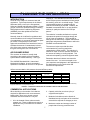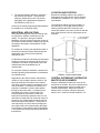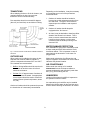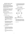
1
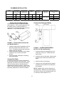
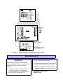
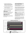
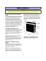
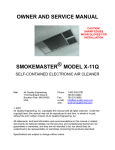
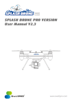
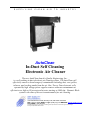
S U P P L Y I N G C L E A N A I R T O I N D U S T R Y AutoClean In-Duct Self Cleaning Electronic Air Cleaner The new AutoClean from Air Quality Engineering, Inc., is a self washing in-duct electronic air cleaning system. The AutoClean will effectively remove a broad range of contaminants including dust, soot, pollen, tobacco, and cooking smoke from the air. One, Two or Four electronic cells, operated by high voltage power supplies remove airborne contaminants at efficiencies as high as 99 percent and at rates starting at 1000 cfm. Dynamic Wash system is the state-of-the-art in maintenance free air cleaning. 7140 Northland Drive North, Brooklyn Park, MN 55428-1520 USA FAX: (763) 531-9900 EMAIL: [email protected] WEB SITE: www.air-quality-eng.com TOLL FREE: 1-800-328-0787 Air Quality Engineering Inc., has a policy of continuing product improvement and reserves the right to make changes in design and specification without notice. Before you get started please review the following: Purchase Date: _____________________ Serial Number: _____________________ Customer Technical Support: To contact Air Quality Engineering use: Mail: Air Quality Engineering 7140 Northland Drive N. Brooklyn Park, MN 55428 USA Phone: 1.800.328.0787 763.531.9823 Fax: 763.531.9900 e-mail: [email protected] web: www.air-quality-eng.com Copyright Air Quality Engineering, Inc. copyrights this manual with all rights reserved. Under the copyright laws, this manual may not be reproduced in any form, in whole or in part, without the prior written consent of Air Quality Engineering, Inc. 2004 Disclaimer All statements, technical information and recommendations in this manual or related documents are believed reliable, but the accuracy and completeness thereof are not guaranteed or warranted, and they are not intended to be, nor should they be understood to be representation or warranties concerning the products described. Specifications are subject to change without notice. 2 TABLE OF CONTENTS PAGE HOW AIRBORNE CONTAMINATION IS REMOVED 3 DIMENSIONS 4 SPECIFICATIONS 6 PLANNING THE INSTALLATION 7 ASSEMBLY & INSTALLATION 10 CHECKOUT 16 MAINTENANCE 18 TROUBLE SHOOTING 21 PARTS IMAGES & PART NUMBERS 24 WARRANTY 27 HOW AIRBORNE CONTAMINATION IS REMOVED A process called “Electrostatic Precipitation” traps airborne contaminants. The fan draws particulate laden air successively through the prefilter, the cell ionizing section and the cell collector section. The ionizing section imparts an electrical charge to the individual particles that are then drawn by electrostatic forces to the oppositely charged collector plates. Cleaned air is then discharged back into the room. The electronic cells must be washed periodically to maintain efficient performance. 3 DIMENSIONS AutoClean 2000 AutoClean 4000 AutoClean 8000 1.50 METRIC CONVERSION Ins. to mm Lbs. to kgs. Ins. w.g. to kPa CFM to m³/h Ft² to m² AutoClean 2000 AutoClean 4000 AutoClean 8000 FORMULA Ins. x 25.4 Lbs. x .455 Ins. w.g. x .2488 CFM x 1.6992 Ft² x .0929 SHIPPING WEIGHT Lb. Kg. 290 390 600 131.5 177.0 272.2 INSTALLED WEIGHT Lb. Kg. 240 340 530 108.9 154.2 240.4 5 SPECIFICATIONS - IMPORTANT THE SPECIFICATIONS GIVEN IN THIS PUBLICATION DO NOT INCLUDE NORMAL MANUFACTURING TOLERANCES. THEREFORE, THIS UNIT MAY NOT MATCH THE LISTED SPECIFICATIONS EXACTLY. ALSO, THIS PRODUCT IS TESTED AND CALIBRATED UNDER CLOSELY CONTROLLED CONDITIONS AND SOME MINOR DIFFERENCES IN PERFORMANCE CAN BE EXPECTED IF THOSE CONDITIONS ARE CHANGED. SPECIFICATIONS Cabinet: 16 gauge welded steel cabinet with a powder coat finish. Instrumentation: Indicator Light – Light indicates that the collector cells are energized properly. Electrical Rating: AutoClean In-place Wash Electronic Air Cleaner-120V/240V, 60 Hz; or 220-240V, 50 Hz Ambient Temperature Rating: Airflow through cells: 125°F [52°C] max., 40°F [5°C] min. Power Ratings: MODEL AutoClean 2000 AutoClean 4000 AutoClean 8000 Pre/post Filter: AIR CLEANER ON CYCLE MAX. NOM. NOM. W W VA 90 55 75 90 70 85 140 120 170 WASH CYCLE MAX. NOM. NOM. W W VA 145 105 170 145 105 170 145 105 170 2000: 2 x 41022 2’ x 2’ aluminum mesh filters. 4000: 4 x 41022 2’ x 2’ aluminum mesh filters. 8000: 8 x 41022 2’ x 2’ aluminum mesh filters. Primary Filter Options: 2000: 1 x 38010 ~ 24”h x 24”w x 10.75” deep or 2 x 38003 ~ 24”h x 12”w x 10.75” deep 4000: 2 x 38010 ~ 24”h x 24”w x 10.75” deep or 4 x 38003 ~ 24”h x 12”w x 10.75” deep 8000: 4 x 38010 ~ 24”h x 24”w x 10.75” deep or 8 x 38003 ~ 24”h x 12”w x 10.75” deep Optional Carbon Filter: Custom carbon modules available Optional Blower Module: Custom blower modules available Optional Enclosure and Mounting: Optional outdoor weather enclosure and mounting skid available Air Quality Engineering, Inc., has a policy of continuing product improvement and reserves the right to make changes in design and specifications without notice. 6 PLANNING THE INSTALLATION outdoor air. The Standard recommends as much as 50 CFM per person ventilation air where people are smoking, such as in a cocktail lounge. These recommended outdoor air quantities may be reduced if air cleaning is provided. However, the Standard recommends that “in no case shall the outdoor air quality be less than five CFM per person.” INTRODUCTION Clean air is the subject of numerous laws and regulations. Typical requirements in the United States are those put out by the Occupational Safety and Health Administration (OSHA). Private groups, such as the American Society of Heating, Refrigeration and Air Conditioning Engineers (ASHRAE), have also published numerous recommendations. The reduction in outside ventilation air required represents the potential for savings through the use of clean recirculated air. This potential for savings can be achieved by a system that reduces particulate and gaseous contaminants to within the ASHRAE recommended limits. Normally, clean air is defined in regulations and recommendations as air having a limited amount of contaminant in it, commonly expressed as parts per million or milligrams per cubic meter. Approved counteractions are intended to lower or eliminate the amount of contaminants in the air. One of the more common methods of achieving this goal is through the use of air cleaners. The AutoClean helps to provide this clean, recirculated air by removing particulate contamination (visible smoke). The reduction in outdoor air used, of course, means a reduction in the amount of heating or cooling required. This reduces both operating cost and equipment wear. AIR CLEANER SIZING The AutoClean air cleaner is usually sized according to the capacity of the air handling system and the desired efficiency. See Fig. 3. Remember that the air cleaner must meet the needs of the user. You are encouraged to use your experience and judgment in the application of this data keeping in mind local codes and minimum air requirements. The ASHRAE Standard 62-81, Natural and Mechanical Ventilation, gives recommended quantities of ventilation air in terms of 100 percent Airflow recommendation with pressure drop and efficiency rating: F 61 A 3 cfm M / hr 1000 1699 1500 2548 2000 3398 2500 4248 3000 5296 F 61 B 3 cfm M / hr 2000 3398 3000 5097 4000 6796 5000 8495 6000 10,194 F 61 C 3 cfm M / hr 4000 6896 6000 10,194 8000 13,592 10,000 16,990 12,000 20,388 Efficiency (Percent) 99 99 95 90 80 Water Pressure Drop In. KPa 0.06 0.015 0.12 0.030 0.22 0.550 0.33 0.830 0.49 0.122 Efficiency ratings based on National Bureau of Standards Dust Spot Method and American Society of Heating, Refrigerating and Air-Conditioning Engineers Standard 52-76, using atmospheric dust. FIGURE 3 – AutoClean ELECTRONIC AIR CLEANER CAPACITY AND EFFICIENCY COMMERCIAL APPLICATIONS 2. Capacity cubic feet per minute (cfm) of equipment and system. When deciding on the number of air cleaners required for applications such as a restaurant, bowling alley, store, bar or lounge, several conditions must be considered. They are: 3. Method of calculation-must be forced air, distributed evenly to all parts of the controlled area with the required air changes per hour. 1. Air to be cleaned of dust, tobacco smoke, greases, etc. These conditions may require a higher efficiency in the electronic air cleaner installation. 4. Maximum number and average number of people that will occupy controlled area. 7 LOCATION AND POSITION 5. The percent operating efficiency required of the electronic air cleaner. The AutoClean efficiency should be from 85 to 95 percent depending on the application and purpose. See Efficiency Chart, Fig. 3. Because air-handling systems vary greatly in arrangement and style, factors such as location, air distribution, transitions, etc., require careful consideration. The AutoClean cabinet must be mounted in a horizontal duct in an upright position with the washing manifold above the electronic cells. Locate the cabinet in the return air duct so that the face of the electronic cell is at right angles to the airstream. Contact an Air Quality Engineering Representative for assistance on commercial sizing. INDUSTRIAL APPLICATIONS Sizing is determining how many air cleaning units are required to maintain a desired level of air quality. The process to sizing an industrial application involves roughly figuring the number of air cleaners needed and then modifying the figures according to the specific characteristics of each application. For ambient air cleaning, the estimated number of electronic air cleaners may be determined by the relationship of air volume to the needed air changes per hour. An alternative method for calculating the estimated number of electronic air cleaners can be used if it is possible to measure the generation rate of the contaminants and the allowable level of contamination. To use either method of calculation, contact an Air Quality Engineering Representative for assistance on industrial sizing. FIGURE 4 – TYPICAL INSTALLATION CENTRAL DETERGENT SYSTEM FOR MULTIPLE AIR CLEANERS Regardless of the method used to calculate the number of units needed to produce clean air, the physical conditions of the space to be cleaned may either limit this number or demand that more units be installed. For ambient air cleaning, it is important to establish a uniform airflow pattern throughout the entire space. Limitations to the calculated sizing may be a lack of space for mounting areas or the number of units may interrupt normal building operation; that is, a unit cannot be mounted where an overhead crane will smash into it or where stand mountings seriously interrupt building traffic patterns. The number of units required by air volume and air changes per hour might need to be increased when the shape of a structure is such capturing and air distribution is not possible according to the sizing calculations that effective. When the installation includes two, three or four AutoClean air cleaners, they can be positioned so that the wash detergent can be pumped from a centrally located bottle. Maximum horizontal distance from air cleaner cabinet to detergent bottle is 20 ft., maximum vertical distance is 7 ft. 8 Depending on the installation, it may be necessary to incorporate some or all of the precautions mentioned below: TRANSITIONS When adapting the duct to fit the air cleaner, use gradual transitions in duct size to prevent turbulence and to increase efficiency. 1. Outdoor air intakes should be hooded or louvered to provide adequate protection from rain and snow. The type of hood used will depend upon the installation and expected weather. Duct transitions should not exceed 20 degrees (about 4” per lineal foot) on each side of a fitting. 2. Outdoor air intakes should always be equipped with a “bird screen.” 3. At times it may be desirable to install a prefilter ahead of the electronic air cleaner. This is done to remove contaminants that could be harmful to the air cleaner or might cause excessively fast dirt buildup or arcing in the electronic cell. WATER DAMAGE PROTECTION If the installation is going to be overhead, provide a sheet metal pan with a drain under the entire AutoClean cabinet. This is important in case of water leaks in the ductwork or in the case of a plugged drain. Fig. 5: TYPICAL INSTALLATION WITH TURNING VANES IN AIR DUCT OUTDOOR AIR When outdoor air is added to the return air duct, sufficient heat must be added to maintain a uniform a temperature between 50°F and 125°F. Two methods are recommended: Make certain a drainpipe of sufficient size and slope is roughed-in to the bottom of the air cleaner cabinet at the planned location. 1. Baffles. Mixing baffles should be used to mix the outdoor air and the return air before it enters the air cleaner. Make certain the cooling coil is installed downstream from the air cleaner cabinet to prevent condensation and chilled air (cooler than 40°F [5°C]) from entering the cell. 2. AIR CONDITIONING Preheat Coil. If large amounts of outdoor air are used, it must be heated. An appropriate control system should be used to control the heating element (electric strip heater, steam coil, etc.). HUMIDIFIERS Location of the system humidifier is important to the operation of the air cleaner. An evaporative type humidifier may be installed between the furnace warm air duct and the return air duct without affecting the electronic air cleaner. Outdoor air intakes should be protected to prevent the introduction of unnecessary contaminants. 9 ASSEMBLY & INSTALLATION - IMPORTANT This section includes information for the sheet metal, plumbing and electrical installation. Make certain each person involved with the installation is aware of the appropriate subsections in the manual. - INSTALLATION CHECK LIST -Transitions -Turning Vanes -Components Assembled Electronic Cells -Wiring -Activated Carbon Filters Required? -Hot Water Supply Line -Pressure Regulator Required? -Water Strainer -Drain Connected -Check Packing Materials Before Discarding - CAUTION Do NOT connect the power source until after the air cleaner is completely assembled. If the air cleaner must be turned on for an electrical check, be extremely careful in avoiding electrical shock. Also, take care to avoid the air cleaner’s moving parts. UNPACKING Remove all shipping cardboard and banding. Be sure to inspect the packaging material before discarding it. 4. Drain connection. WHEN INSTALLING THIS PRODUCT 6. Sequence controller. 5. Water strainer. 7. Accessories, if ordered. 1. Read these instructions carefully. Failure to follow them could damage the product or cause a hazardous condition. 2. PLACEMENT OF THE AIR CLEANER Depending on the placement of the air cleaner (roof top for example) a lifting crane might be necessary. Make sure that the air cleaner and components are properly supported before lifting. After installation is complete, check out product operation as provided in these instructions. All components are individually packaged and shipped in one large box. Before proceeding, carefully open each carton and visually check for possible damage to the air cleaner components. If placing on a rooftop make sure there is proper clearance between the rooftop and the air cleaner. This can be achieved with mounting beams or by keeping the lifting supports in place. 1. Cabinet with control box mounted. 2. Electronic cell (1-8 cartons depending on model ordered). If the air cleaner is installed in a location where water damage is possible, install a sheet metal pan with drain under the air cleaner cabinet and sloped ductwork. 3. Legs with leveler screws and mounting bolts. 10 c. SHEET METAL INSTALLATION Air Distribution and Ductwork The AutoClean operates most efficiently when all system air is delivered across the electronic cell at a uniform velocity. Turning vanes should be added to any return airdrop upstream from the air cleaner. See Fig. 5. Use caulking compound (not furnished) to seal the flange joints and all ductwork joints on both the inlet and outlet sides. Seal all joints for at least 3 ft. from cabinet. FILTER PLACEMENT 1. Slide prefilters into shield channels and push all the way to the back of the cabinet. Gradual transitions to the AutoClean cabinet are recommended in all ductwork larger or smaller than the cabinet opening. If transitions are used, they should not exceed 20 degrees (4” rise per linear ft. Install the Air Cleaner Mount the AutoClean Air Cleaner as Follows: 1. Fabricate and install the necessary vanes and transitions. 2. Set the cabinet in position. a. If feet are used, mount the feet on the AutoClean cabinet and adjust all four feet-leveler screws. The bottom of the cabinet must be level. This will provide for proper drainage of water from the bottom of the cabinet. Maximum adjustment is 1 ¼ in. for each leveler screw. FIGURE 6 – CORRECT CELL ORIENTATION IN AutoClean 2. Insert the electronic cells into the cabinet with THIS SIDE OUT label facing the door opening. Make certain the arrow stamped on the cell points downstream. See Fig. 6. b. If hanging brackets are used, make certain the brackets are strong enough to hold the cabinet and the cabinet is attached firmly to the brackets. c. 3. Close the door. Leave clearance above the control box to remove the cover and apply a wrench to the water strainer. 3. Ductwork preparation a. Drill clearance holes for sheet metal screws in the cabinet flanges which will not cause leaking. Remember that the ductwork must be water-tight near the cabinet. b. Fasten the duct to the inside of the cabinet flange opening with sheet metal screws. 11 PLUMBING INSTALLATION Model AutoClean 2000 AutoClean 4000 AutoClean 8000 Recommended Min. Water Pressure during Wash psi kPa 25 25 25 172.4 172.4 172.4 Recommended Hot Water Tank Size (Minimum) Hot Water per Wash Washes per unit of detergent Gallon Liter Gallon Liter Gallon Liter 40 50 100 151.4 189.3 378.5 35 60 112 132.5 227.1 423.9 20 10 6 5.3 2.6 1.6 Recommended wash water temperature 125 to 160 deg F ( 52 to 71 deg C) Maximum water flow rate @ 30 psi (206.8 kPa) Gal / min 4 7 14 Liter / min 15.1 26.5 53.0 Figure 7 – Hot Water and Detergent Requirements Connect the Hot Water Supply Connect the Detergent Bottle Plumbing must comply with applicable codes and regulations. The hot water supply line from the heater to the air cleaner should be ¾” copper pipe for AutoClean 2000 and AutoClean 4000 and 1” for the AutoClean 8000. FIGURE 8 – TYPICAL INSTALLATION FOR HOT WATER SUPPLY 1. Install the water strainer (supplied) in the hot water line ahead of the water valve. See Fig. 8. The strainer protects the valves and washing jets from clogging. 2. Attach the pressure regulator valve (if water pressure is over 75 psi ) to the water strainer. 3. Connect a faucet, if desired, for checking water temperature. FIGURE 9 – CONNECTING DETERGENT BOTTLE TO THE CONTROL BOX 1. Insert the plastic hose (supplied) over the metal tube. See Fig. 9. Fasten the hose with a clamp. 2. Insert the hose into the bottle. Make certain the filter screen rests on the bottom of the bottle. Connect the Drain Connect the drain spud (2 inch) in the base of the AutoClean cabinet to the waste drain. Use a water trap or check the valve to prevent sewer odor from entering the air cleaner base and spreading through the air system. Follow local codes. Test may have to be preformed to check total water quality after air cleaner is installed. 3. Place the bottle on the hanger. 4. Close the top of the bottle with the stopper provided to prevent debris from falling into the detergent. NOTE: Multiple hoses can be inserted into a detergent bottle. Maximum horizontal distance from the air cleaner to the detergent bottle is 20 ft., maximum vertical distance is 7 ft. 12 Follow figures 10, 11 12, and 13 for making all the appropriate electrical connections. Figures 10 and 11 are of the internal wiring diagrams for each unit. Figures 12 and 13 are of the total wiring diagrams for the units. Notice the three boxes surrounding the Unit, Timer, and HVAC system. All wires that appear outside of these boxes need to be added by the installer. ELECTRICAL INSTALLATION All wiring must comply with applicable local codes and ordinances. The power supply to the AutoClean air cleaner must be 120V or 240V, 60 Hz, or 220-240V, 50 Hz. Refer to the AutoClean nameplate for the proper voltage for your air cleaner. Use color-coded wires and attach all connections with solderless connectors or to the screw type terminals. FIGURE 10 – INTERNAL WIRING SCHEMATIC FOR AUTOCLEAN 2000 AND 4000 13 FIGURE 11 – INTERNAL WIRING SCHEMATIC FOR AUTOCLEAN 8000 14 FIGURE 12 – WIRING SCHEMATIC FOR TYPICAL HVAC SYSTEM 15 FIGURE 13 – WIRING SCHEMATIC FOR EXHAUST FAN SYSTEM CHECKOUT 3. Check over the installation for correct sheetmetal, plumbing and electrical work. - IMPORTANT Before putting the AutoClean In-Place Wash Electronic Air Cleaner into service, check through the following items to be sure it is properly installed. 4. Turning vanes should be used in duct elbow to provide even air distribution across the cell. 5. When it is necessary to change the duct size close to the air cleaner, use gradual transitions to reduce turbulence. 2. If outdoor air is used, care must be taken to prevent direct delivery of cold outside air across the electronic cell. Preheat the air in some manner or mix with return air. GENERAL COMPONENT INSPECTION 16 1. Check for proper orientation of the electronic cells, protective screens and spray shield. Airflow arrows must point downstream. Protective screens must be on both sides of the electronic cells. CHECK THE ELECTRONIC CELLS AND THE POWER SUPPLY 2. Be sure that the electronic cells, protective screens and spray shields are clean, dry and free of foreign objects. Check the indicator light on the power door. It should be on. With the power supply energized, momentarily open the access door. When the door opens the indicator light should go out. With all components in place and the access door closed, energize the system fan and turn on the electronic air cleaner. 3. Be sure the spray manifold is located in the cabinet with nozzles pointed toward the cells. If the power supply and electronic cells do not check out properly in this procedure, refer to the TROUBLESHOOTING section for additional checks. CHECK THE JUNCTION BOX CONNECTIONS CHECK THE AUTOMATIC WASHING CYCLE Check all electrical connections to make certain they are correct and complete. Refer to the hookup diagrams (Figures 9 through 13). The wash cycle for the electronic cell is controlled by the built-in sequence timer and the washing assembly is operated by a motor. The wash cycle may be manually activated by pressing the button. Remove and visually check cell and screens for dirt. CHECK THE PLUMBING CONNECTIONS Check to be sure all plumbing work including the hot water supply and the drain are correct and will not leak! The manifold motor operates a cam and gear assembly to slowly move the manifold (water pipe and spray nozzles) during the wash cycle. Make sure there is complete coverage of the cells during a wash cycle. SEQUENCE TIMER OPERATION SYSTEM SHUT DOWN - 1MIN, WASH - 2MIN, RINSE - 5 MIN, DRY - 45 MIN EAC POWER SUPPLY SYSTEM FAN DETERGENT PUMP HOT WATER VALVE DETERGENT VALVE MANIFOLD MOTOR SYSTEM HEATING SYSTEM COOLING 0 2 4 6 8 10 12 14 16 18 20 22 24 26 28 30 32 34 36 38 40 42 44 46 48 50 52 54 56 58 60 TIME (MINUTES) OPERATES AT DEMAND OF PRIMARY CONTROL CIRCUIT OFF CIRCUIT ON Figure - 14 - Sequence Timer Operation 17 MAINTENANCE - CAUTION Always disconnect the power to the AutoClean before working on or near the air cleaner. WHEN TO WASH THE ELECTRONIC CELLS While the cells in the electronic air cleaner are being washed, a musty, dirty odor combined with the characteristic odor of the detergent may be noticed. This is caused when the accumulated dirt on the cells is washed off by the detergent and hot water spray. It will disappear after the washing is complete. To maintain peak performance and efficiency, the electronic cells and spray shields in the electronic air cleaner must be washed regularly. This washing is necessary to remove the dirt particles accumulated during the air cleaning process. The cells and screens should be visually checked for dirt or lint. Experience will probably be the best indicator of how often the cells and screens should be cleaned. For example, when operating in a thick smoke or particularly dirty atmosphere, the cells may need washing twice a week. If the dirt accumulation is light, the period between washings can be lengthened. AUTOMATIC WASHING CYCLE The cell wash cycle for the electronic air cleaner is controlled by a built-in timer sequence and may be activated by a master clock. The washing assembly is operated by a motor. NOTE: For 50 Hz models, the timing will be about one-fifth longer. Make sure that enough hot water is available for washing throughout the entire cycle. In installations with multiple electronic air cleaners, it may be necessary to stagger the timing of the wash cycles. This is to assure adequate water pressure for washing. FIGURE 15 – PN 38010, ELECTRONIC CELL COMPONENTS. DIMENSIONS IN INCHES [MILLIMETERS SHOWN IN BRACKETS]. MANUALLY STARTING A WASH CYCLE The electronic air cleaner is equipped with an automatic wash control box. When an extra wash cycle is desired, it may be manually started by pushing the labeled button. NOTE: The complete cycle takes about 70 minutes. For the first 15 minutes when water is being sprayed in the electronic air cleaner, the heating or cooling system is automatically turned off. 18 REPLENISH THE DETERGENT SUPPLY WASHING THE CELLS OUTSIDE THE ELECTRONIC AIR CLEANER After routine washing, a noticeable buildup may remain on some parts of the cells. This is normal and has only a negligible effect on performance. - IMPORTANT Replenish the detergent supply in the bottle before it is completely empty. If detergent is allowed to dry in the bottom of the hose or bottle, the hose may become plugged. After a long period of service, perhaps every one to three years, the electronic cells should be removed from the cabinet and given an extra thorough washing. In many areas, professional cell cleaning services are available or they may be returned to Air Quality Engineering for a professional cleaning. Replenish the detergent supply as follows: 1. Remove the stopper and hose from the nearly empty bottle. The spray shields may be washed along with the electronic cells. Before doing this, however, remove the lint from the screens to prevent getting lint caught in the electronic cells. 2. Insert the hose into a new, full bottle or refilled bottle. Make certain that the filter screen at the end of the hose rests on the bottom of the bottle. REMOVE THE CELLS AND THE SCREENS 3. Hang the bottle on its hanger or replace it where the first bottle was placed. 1. Use care to avoid damage to the collector plates when handling and washing the cells. 4. Close the top of the bottle with the stopper provided to prevent debris from falling into the detergent. 2. Pull the handle to slide the cells out. Note the direction of the airflow arrows on the cells. 3. Pull the screen out. Vacuum or dust loose dirt in the cell or screen tracks. NOTE: Maximum horizontal distance from the air cleaner to the detergent bottle is 20 ft. [6.1 m]. Maximum vertical distance from the air cleaner to the bottle is 10 ft. [3.0 m]. MANUALLY CLEANING CELLS Depending on the type of contaminant, different cleaners will be required. Smokemaster liquid detergent will be adequate to remove almost any type of dust, dirt, pollen and tobacco smoke. A cleaner, such as AQE’s welding detergent part number 45026, will remove metal oxides such as those produced by welding. A cleaner, such as AQE’s degreaser part number 45031, will remove greases associated with kitchen hoods. Smokemaster has 1 gal. [3.8 L] bottles and 55 gal. [208.0 L] drums of liquid detergent available. MANUALLY CLEANING CLEANING THE SPRAY SHIELDS The spray shields in front of the electronic cells help stop lint and other large particles. It’s a good idea to check these shields periodically to be sure they are not overloaded. - CAUTION - At intervals of about one year, the spray shields should be removed to clean off the accumulated lint. An overloaded shield screen can restrict the airflow through the heating or cooling system. Do not splash the cleaning solution in your eyes and avoid prolonged contact with your skin. Keep the detergent and solution out of the reach of children. Be sure to follow the cleaning solution label instructions for use or storage. The shields may be cleaned in several ways: - spray with a garden hose - vacuum or - knock the dirt off onto a paper by striking the screen against the floor. 1. Mix the cleaning solution according to the label instructions. 19 other short in the charging section, is indicated by the status light on the power door. Broken wires must be replaced. Remove all parts of the broken wire and temporarily use the cell short of one wire until it can be replaced as directed below. See the PARTS LIST to order wires. 2. Soak the cells for the time indicated on the cleaning solution label. Before removing the cells, slosh them around several times. 3. Rinse the cells with a fine spray. 4. Soak the cells and let the water drain. If the water draining from the cells feels slippery, they need more rinsing. To replace the ionizing wires, remove the electronic cell from the cabinet and proceed as follows: 5. Inspect the cells for cleanliness. If any dirt remains, it probably indicates that the cells should be washed more frequently. Repeat this soaking procedure, if needed, to get the cells clean. 1. Remove all of the broken wire from the cell mounting brackets. See Fig. 16. 2. Install the new wire. a. Insert the “T” end of the ionizing wire into the keyhole spring until the hooked end can be secured in the mounting bracket hole. REPLACE THE ELECTRONIC CELLS AND THE SPRAY SHIELDS 1. Replace the electronic cell so that the arrow on the handle-side of the cell points in the direction of the airflow. Use a long nose pliers and carefully pull the spring until the hooked end can be secured in the mounting bracket hole. 2. Insert the spray shields in the channels provided. 3. Replace and close the power door. NOTE: The just washed cell may be replaced in the cabinet even though it is still wet. The system light may come on during the normal drying period. IONIZING WIRE REPLACEMENT The fine wire electrodes in the charging section of the electronic cell may break or become damaged. During operation, a broken or deformed wire generally causes a short to ground, possibly with visible arcing or sparking. This condition, or any FIGURE 16 – METHOD OF REPLACING THE IONIZING WIRE 20 TROUBLE SHOOTING WARNING! The following instructions are intended for qualified service personnel only. Dangerous line voltage circuits are exposed during this procedure. Disconnect the power before servicing the unit. Voltage may exceed 10,000 Vdc. Make sure meter to be used has appropriate voltage rating. Before beginning this section make sure to review the checkout and maintenance sections! Make sure all wiring is connected properly reference figures 8, 9, 10, and 11. FIGURE 18 - SEQUENCE CONTROLLER FIGURE 17 - CONTROL BOX COMPONENTS Indicator light flickers / Unit makes zapping noises Some flicker is inherent in neon indicator lights and is not an indication that anything is wrong. If the indicator light blinks off and back on and is accompanied by a clicking or zapping noise that is frequent, it is an indication that the electronic collector cell(s) may be dirty or damaged. A wash cycle should be performed to clean the cell. An occasional blink or snapping is normal. If the wash cycle does not eliminate the noise remove the cells and investigate them looking for bent collector fins or a large particle stuck in a cell. Also check the contacts on the cells and inside the unit for a possible bad connection. Remove any particles taking care not to bend the collector plates or break any ionizing wires. If any ionizing wires are broken reference the parts list for replacement. If a collector plate is bent causing the arcing (bug zapper noise), one may attempt to bend the plate back to an original position with a duckbilled pliers. Care must be used as further damage can be caused by stretching the aluminum plates, which can render the cell unrepairable. Air Quality Engineering will 21 evaluate cells at no charge and provide free repair estimates. This is highly recommended before untrained personnel attempt repairs. Please contact Air Quality Engineering at 1-800-328-0787 for assistance. Indicator light is NOT on Check to see if the wash system is operating. The indicator light should not be lit when the wash system is activated. Check to see if the cell access door is closed properly. The indicator light will not be lit if the door is open and the electronic cells will not be energized. Be sure the electrical connections have been made properly per Figure 10 & 11, particularly that a lead was made from the fan motor to terminal 16A on the sequence controller. This supplies power to the sequence controller when the fan is operating which in turn supplies power to the power supply. Remove the electronic collector cell(s) and close the door. If the light comes back on, there is a short in at least one collector cell. A short can be a result of the cell(s) being excessively dirty, a large piece of contaminant shorting the fins, or a physical damage such as a collector fin being bent out of shape and touching an adjoining fin. The wash cycle may be run to clean the cells if they appear dirty. Visually inspect the cell for large particulate that may be bridging two adjoining collector fins or for physical damage. If damage is identified, repairs should only be performed by trained personnel as improper repairs may result in unrepairable damage. Please contact Air Quality Engineering, Inc. at 1-800-3280787 for assistance. Cells may be returned for free repair estimates. If the indicator light does not come on with the cells removed and the door closed, use a voltmeter to confirm that there is indeed voltage at the input of the power supply. If there is voltage at the power supply, but no indicator light, the power supply should be replaced. The indicator light itself has a very low failure rate. Water not Flowing There are two valves in series. The first valve (the one on the left) is an open/closed valve while the second valve is a flow control valve (meaning its positions are fully open/partially open). Check to make sure the first valve is getting energized (it is fail closed). One should hear a clicking from the solenoid during as the sequence controller engages and disengages the solenoids. If this is not occurring one could check this by manually taking apart the hot water solenoid, or a new assembly might have to be installed. Detergent not Flowing During the wash cycle the valves should open and close allowing detergent to be pumped from the container and sprayed from the manifold jets. If the detergent is not being sprayed check for the following: If the detergent supply bottle is empty. If the detergent supply tube is restricted. If the detergent pump is running. The detergent pump makes a significant amount of noise and should be audible while it is running. If the pump is not running, check to make sure it is receiving voltage, if not, the sequence controller has an LED indicator for the detergent pump, if the LED does not light, sequence controller may need to be replaced. If it does light, but pump does not run, the pump may need to be replaced. 22 Too much detergent being used The length of time the detergent pump is on during the wash cycle can be manually changed on the sequence controller by rotating the potentiometer. Mechanical wash system not working (the nozzles are not turning or not traversing along the cells, during the wash and rinse cycle.) The manifold motor operates both the rotation and traversing motion of the jets. Check to see if the manifold motor is operating. If the motor is still not operational check to see if it is getting voltage. If no voltage is getting to the motor trace wiring back and find the break. If voltage is getting to the motor and still no movement is coming from the motor the motor will need to be replaced. Reference the parts list for replacement. Make sure that the linkage is not being stopped by an obstruction. Nothing happens when the start button is depressed Check inside the NEMA box of the sequence controller to see if the LED lights light up when you push the start button. If they do, the sequence controller is not properly wired to the AutoClean. Check the electrical schematics for proper wiring. If the LEDs do not light up when the start button is depressed, check to see that voltage is being supplied to the sequence controller. If voltage is present, but the LEDs won’t light, replace the sequence controller. Fan will not turn off during a wash cycle If the fan does not turn off reference the wiring diagram to make sure it wired properly. The fan relay coil should be energized or de-energized by terminal 15 of the sequence controller. 23 PARTS IMAGES & PART NUMBERS 24 ITEM NO. DESCRIPTION 1 Spray Shield, Pre/Post Filter 24 5/8” x 24” x ¼” Industrial Cell Full Size Industrial Cell Half Size Ionizing wires for Industrial Cell sold in 5 pack Sequence Controller Manual Start switch Power Supply Assy Detergent Valve & Solenoid Assy Detergent Pump Water Valve & Solenoid Assy. Water Strainer Manifold Motor Liquid Detergent (1 gal. [3.78 L]) Liquid Detergent-55 gal. [208.2 L] drum Cell Coat Cell Coat Refill Welding Smoke Detergent (5 Gal) Industrial Cell Cleaning Kit Degreaser (5 Gal.) 2 Not Shown 3 4 5 6 7 8 Not Shown 9 Not Shown Not Shown Not Shown Not Shown Not Shown 25 120V, 60 HZ 41022 38010 38003 38005 45008 45011 45023 45024 45026 66666 45031 PART NO. 240V, 60 HZ 41022 38010 38003 38005 45008 45011 45023 45024 45026 66666 45031 220-240V, 50 HZ 41022 38010 38003 38005 45008 45011 45023 45024 45026 66666 45031 26 CERTIFICATE OF WARRANTY THREE-YEAR LIMITED WARRANTY Air Quality Engineering, Inc. (AQE), warrants to the original purchaser, subject to the conditions below, that if the “Product” covered by this warranty should fail to perform by reason of improper workmanship or material, AQE will during the period of three (3) years from the date of original purchase either (i) replace the product or (ii) provide all necessary parts to repair the product without charge. The decision to replace the product or the necessary parts shall rest solely with AQE. This three-year limited warranty does not apply to main filter elements. AQE will replace without charge the main filter elements during the period of thirty (30) days from the date of original purchase if the main filter elements fail to perform by reason of improper workmanship or material. This warranty is valid only under the following conditions: CONDITIONS 1. REGISTRATION: The purchaser’s completion and mailing of the Registration Card to Air Quality Engineering, Inc., 7140 Northland Drive North, Minneapolis, Minnesota 55428-1520 within 30 days of original purchase. 2. AUTHORIZATION: The purchaser will contact AQE at (763) 531-9823 for authorization, returned goods number (RGA) and the shipping address. AQE will direct the purchaser to either return the necessary parts or the product at AQE’s option. 3. PROPER DELIVERY: The shipping, freight prepaid or delivery of the parts or the product to AQE in either its original carton or in a carton assuring similar protection of the product with the returned goods number (RGA) clearly displayed on the outside of the carton. 4. UNAUTHORIZED REPAIR: A showing by the original purchaser that the product has not been altered, repaired or serviced by anyone other than an authorized service technician using genuine AQE parts. 5. UNAUTHORIZED PARTS: A showing by the original purchaser that the product has had only genuine AQE parts and filters used in its operation and maintenance. 6. SERIAL NUMBER INTACT: A showing by the original purchaser that the serial number has not been altered or removed. 7. MISUSE: A showing by the original purchaser that the product has not been involved in an accident, freight damaged, misused, abused or operated contrary to the instructions contained in the Owner’s Manual. Air Quality Engineering, Inc.’s, sole responsibility shall be to repair or replace the product within the terms stated above. AQE SHALL NOT BE LIABLE FOR ANY CONSEQUENTIAL DAMAGES RESULTING FROM ANY BREACH OF WARRANTY, EXPRESS OR IMPLIED, APPLICABLE TO THIS PRODUCT. Some states do not allow the exclusion or limitation of consequential damages so this limitation may not apply to you. THIS WARRANTY IS IN LIEU OF ALL OTHER WARRANTIES, EXPRESS OR IMPLIED, AND THE WARRANTIES OF MERCHANTABILITY AND FITNESS FOR A PARTICULAR PURPOSE ARE HEREBY EXCLUDED BEYOND THE THREE-YEAR DURATION OF THIS WARRANTY. Some states do not allow limitations on how long an implied warranty lasts so the above limitation may not apply to you. This warranty gives you specific legal rights and you may also have other rights that vary from state to state. AIR QUALITY ENGINEERING, INC. 7140 NORTHLAND DRIVE NORTH MINNEAPOLIS, MINNESOTA 55428-1520 TOLL FREE: 1-800-328-0787 TELEPHONE: (763) 531-9823 FAX: (763) 531-9900 MANUFACTURER & WORLDWIDE DISTRIBUTOR OF SMOKEMASTER® AIR CLEANING SYSTEMS Printed in the USA 27