1
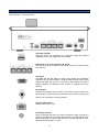
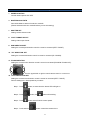
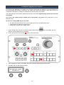
Contents Warnings and Precautions................................................................................................3 Warranty .............................................................................................................................4 Disposal..............................................................................................................................4 Packing List........................................................................................................................4 Introduction........................................................................................................................5 Connections and Controls ................................................................................................6 Connections and Controls ................................................................................................8 Menu Setup ........................................................................................................................9 How to store selected camera positions ....................................................................... 11 Firmware upgrade procedure .........................................................................................12 Service and Support ........................................................................................................16 Disclaimer of Product and Services The information offered in this instruction manual is intended as a guide only. At all times, Datavideo Technologies will try to give correct, complete and suitable information. However, Datavideo Technologies cannot exclude that some information in this manual, from time to time, may not be correct or may be incomplete. This manual may contain typing errors, omissions or incorrect information. Datavideo Technologies always recommend that you double check the information in this document for accuracy before making any purchase decision or using the product. Datavideo Technologies is not responsible for any omissions or errors, or for any subsequent loss or damage caused by using the information contained within this manual. Further advice on the content of this manual or on the product can be obtained by contacting your local Datavideo Office or dealer. 2 Warnings and Precautions 1. Read all of these warnings and save them for later reference. 2. Follow all warnings and instructions marked on this unit. 3. Unplug this unit from the wall outlet before cleaning. Do not use liquid or aerosol cleaners. Use a damp cloth for cleaning. 4. Do not use this unit in or near water. 5. Do not place this unit on an unstable cart, stand, or table. The unit may fall, causing serious damage. 6. Slots and openings on the cabinet top, back, and bottom are provided for ventilation. To ensure safe and reliable operation of this unit, and to protect it from overheating, do not block or cover these openings. Do not place this unit on a bed, sofa, rug, or similar surface, as the ventilation openings on the bottom of the cabinet will be blocked. This unit should never be placed near or over a heat register or radiator. This unit should not be placed in a built-in installation unless proper ventilation is provided. 7. This product should only be operated from the type of power source indicated on the marking label of the AC adapter. If you are not sure of the type of power available, consult your Datavideo dealer or your local power company. 8. Do not allow anything to rest on the power cord. Do not locate this unit where the power cord will be walked on, rolled over, or otherwise stressed. 9. If an extension cord must be used with this unit, make sure that the total of the ampere ratings on the products plugged into the extension cord do not exceed the extension cord rating. 10. Make sure that the total amperes of all the units that are plugged into a single wall outlet do not exceed 15 amperes. 11. Never push objects of any kind into this unit through the cabinet ventilation slots, as they may touch dangerous voltage points or short out parts that could result in risk of fire or electric shock. Never spill liquid of any kind onto or into this unit. 12. Except as specifically explained elsewhere in this manual, do not attempt to service this product yourself. Opening or removing covers that are marked “Do Not Remove” may expose you to dangerous voltage points or other risks, and will void your warranty. Refer all service issues to qualified service personnel. 13. Unplug this product from the wall outlet and refer to qualified service personnel under the following conditions: a. When the power cord is damaged or frayed; b. When liquid has spilled into the unit; c. When the product has been exposed to rain or water; d. When the product does not operate normally under normal operating conditions. Adjust only those controls that are covered by the operating instructions in this manual; improper adjustment of other controls may result in damage to the unit and may often require extensive work by a qualified technician to restore the unit to normal operation; e. When the product has been dropped or the cabinet has been damaged; f. When the product exhibits a distinct change in performance, indicating a need for service. 3 Warranty Standard Warranty • • • • • • • • Datavideo equipment is guaranteed against any manufacturing defects for one year from the date of purchase. The original purchase invoice or other documentary evidence should be supplied at the time of any request for repair under warranty. Damage caused by accident, misuse, unauthorized repairs, sand, grit or water is not covered by this warranty. All mail or transportation costs including insurance are at the expense of the owner. All other claims of any nature are not covered. Cables & batteries are not covered under warranty. Warranty only valid within the country or region of purchase. Your statutory rights are not affected. Two Year Warranty • • All Datavideo products purchased after 01-Oct.-2008 qualify for a free one year extension to the standard Warranty, providing the product is registered with Datavideo within 30 days of purchase. For information on how to register please visit www.datavideo.com or contact your local Datavideo office or authorized Distributors Certain parts with limited lifetime expectancy such as LCD Panels, DVD Drives, Hard Drives are only covered for the first 10,000 hours, or 1 year (whichever comes first). Any second year warranty claims must be made to your local Datavideo office or one of its authorized Distributors before the extended warranty expires. Disposal For EU Customers only - WEEE Marking. This symbol on the product indicates that it should not be treated as household waste. It must be handed over to an applicable take-back scheme for the recycling of Waste Electrical and Electronic Equipment. For more detailed information about the recycling of this product, please contact your local Datavideo office or your local recycling centre. Packing List The following items should be included in the box. If any items are missing please contact your supplier. Item No. Description Quantity 1 RMC-180 CCU Control Box 1 2 Accessory kit * 1 3 Instruction Manual 1 *The accessory kit also contains a packing list. 4 Introduction The Datavideo RMC-180 Controller can control up-to 4 Datavideo Pan Tilt Zoom (PTZ) cameras such as the PTC-100. It can also control third party cameras that use the same PELCO control protocol. That’s Datavideo; sharing the value! To get more value out of your equipment please take a few minutes to read through this manual. This will help you to familiarise yourself with all the aspects of the RMC-180 CCU Controller unit. Features • Remote control of up-to four Pan,Tilt and Zoom cameras • • • • • • • Pan,Tilt and Zoom with speed control by large joystick Control of Pan, Tilt and Zoom as well as Iris, Focus, Gain, and other functions over Ethernet Multiple preset for Pan, Tilt & Zoom for each individual camera Full remote control of each camera via serial communication over affordable network cabling Compatible with Datavideo's switcher tally indicators Compact design for easy installation Easy integration with Datavideo HD switchers for an affordable multi-camera solution. Compatible Control Standards Depending on your chosen PTZ camera(s) the following control standards are available. Please note a firmware update may be required to switch your RMC-180 to the same protocol as the camera you wish to control. All units are initially supplied with the PELCO protocol as this works with the Datavideo PTC-100 camera. • • • PELCO ( PTC-100 camera ) Panasonic ( AW-HE50S/H cameras only ) SONY VISCA ( Firmware being developed ) 5 Connections and Controls Front Panel – Keyboard LCD Display The status of the RMC-180 or the set up menu options are displayed on this LCD panel. Menu Control Dials The RMC-180 configuration menu can be entered and changed using these dials. FOCUS To manually control focus adjustment first press the AUTO/MANUAL button so it is illuminated or ON. The FOCUS dial can then be turned to achieve the desired focus. If the AUTO/MANUAL button is not illuminated or OFF, then the camera will use its own Auto Focus feature, if it has this function. Mode Select MODE The selected PTC-100 camera will output colour bars. A,B Save MODE A or MODE B ATW Force Automatic White Balance 6 IRIS To manually control Iris adjustment first press the AUTO/MANUAL button so it is illuminated or ON. The IRIS dial can then be turned to achieve the desired exposure. If the AUTO/MANUAL button is not illuminated or OFF, then the camera will use its own Auto Iris feature, if it has this function. Channel A, B, C, D buttons To control or set up a connected camera first select it using these buttons. The selected camera button will be illuminated or ON. PTZ Joystick Control Before attempting to use the joystick to PAN, TILT or ZOOM a selected camera first unlock the joystick by pressing the LOCK button. PAN – Move the joystick horizontally to the left or right to pan the selected PTZ camera head from left to right or vice versa. TILT – Move the joystick up or down to tilt the selected camera head up or down. ZOOM – Twist the joystick clockwise (to the right) or anti-clockwise (to the left) to have the selected camera zoom in or out. Speed The speed at which the selected camera moves can be chosen by pressing one of three speed buttons. STR Pressing this button toggles RMC-180 into or out of STORE MODE. When active this allows the current camera position to be stored within a chosen Channel Memory Button. Channel Memory Buttons These buttons may be used to store up to four camera positions for each camera. Each button relates to only one camera and one stored position. The active button for each camera is illuminated. Tally Indicator LEDs Above each set of four memory buttons is a Tally Indicator LED. This LED feature becomes active when the RMC-180 is connected to the tally output of a compatible Datavideo Switcher such as the HS-2000L. When the HS-2000L Switcher is sending camera A’s video to the program output then CH A’s tally LED will be illuminated on the RMC-180. Additional equipment and cabling required. 7 Connections and Controls Rear Panel – Connections Firmware Upgrade USB type A port, for connection to a computer during the firmware upgrade process. See page 12 for more details. RJ45 ports to connect cameras A, B, C & D Four RJ-45 ports are provided on the RMC-180 rear to connect each PTZ camera. Tally Input The RMC-180 has the ability to receive tally signals from Datavideo Switchers such as the HS-2000L. Using the video switcher’s tally output signals, the RMC-180 can turn on an LED on the keyboard, giving the camera operator an indication which camera is currently live at the switcher. DC In Socket Connect the supplied 12V 0.5A PSU to this socket. The connection can be secured by screwing the outer fastening ring of the DC In plug to the socket. The connection is centring positive. Power On/Off Switch Switches the unit On / Off. Grounding Terminal When connecting this unit to any other component, make sure that it is properly grounded by connecting this terminal to an appropriate point. When connecting, use the socket and be sure to use wire with a crosssectional area of at least 1.0 mm2. 8 Menu Setup 1. POWER CONTROL Control camera power ON / OFF. 3. WHITE BALANCE STR Save white balance status of mode A or mode B. (Please selected mode A or mode B before you into this setting) 7. SHUTTER SET Setting camera shutter mode 8. VOUT FORMAT SELECT Setting video output format 9. PAN DIRECTION SET Setting the camera pan direction control is normal or reversed (LEFT / RIGHT). 10. TILT DIRECTION SET Setting the camera tilt direction control is normal or reversed (UP / DOWN). 11. ZOOM DIRECTION Setting the camera zoom direction control is normal or reversed (ZOOM IN / ZOOM OUT). Turn the joystick left or right is control camera zoom in or zoom out. 12. FOCUS DIRECTION SET Setting the camera focus direction control is normal or reversed (LEFT / RIGHT). FOCUS setting has 4 kinds speed let you select: Step 1 - Push button, at same time the button LED will light on. Step 2 - Push Step 3 - Push button, the button will twinkling. button select FOCUS control speed. Step 4 - Push and turn button control the camera focus. 9 13. IRIS DIRECTION SET Setting the camera direction control is normal or reversed (LEFT / RIGHT). IRIS setting has 4 kinds speed let you select: Step 1 - Push button, at same time the button LED will light on. Step 2 - Push Step 3 - Push button, the button will twinkling. button select IRIS control speed. Step 4 - Push and turn button control the camera iris. 14. JOYSTICK SENSITIVITY Setting the joystick controls sensitivity. 18. RMC-180 FW VERSION Display the RMC-180 firmware version. 19. AW-HE100 FW VERSION Display the AW-HE100 firmware version. 20. EXIT Exit the set up menu mode. 10 How to store selected camera positions The RMC-180 allows you to store up to four camera positions for each of the four possible cameras, CH A, B, C and D. This means, with four PTZ cameras connected to the RMC-180, up to sixteen camera positions can be stored. NB: The position and settings are stored in the camera and not in the RMC-180. To store a cameras position: 1. Select the camera that you wish to use CH A or CH B or CH C or CH D. 2. Move the camera to the desired position or view using the joystick. Set the focus, Iris and zoom so you are happy with the camera’s video output. 3. Push the STR (store) button and it will be illuminated. 4. Choose one of the selected camera’s four memory buttons to save the current settings for position, Iris, focus and zoom. The selected memory button will be illuminated. 5. Push the STR (store) button again to turn off the store feature and return the RMC-180 to normal operation. 11 Firmware upgrade procedure From time to time Datavideo may release new firmware to either add new features or to fix reported bugs in the current RMC-180 firmware. Customers can update the firmware themselves if they wish or they can contact their local dealer or reseller for assistance should they prefer this method. This page describes the firmware update process and it should take approximately 30 minutes total time to complete. Once started the update process should not be interrupted in any way as this could result in a nonresponsive unit. As well as a working RMC-180 you will need: The latest Firmware Update. This can be obtained from your local Datavideo office. A cable USB A to USB A no longer than 2m. A Windows computer with a USB 2.0 port. 1. Power off RMC-180, and then connect the USB A cable from the port on the RMC-180 rear panel to chosen USB port on the computer. 2. Push and hold down the indicated buttons, all at same time. 3. Ask a colleague to switch on the RMC-180 power whilst still holding down these buttons. 4. The RMC-180 LCD will display as below. 12 5. “RMC-180_U38” will display on the computer as removable storage. 6. Double click on the “RMC-180_U38” storage icon, and then delete “bootcode.bin” file within the next window. 7. Paste the new firmware .bin file into the same place on the “RMC-180_U38” removable storage. 8. Reset the power on the RMC-180. The LCD will then display as below: 9. The unit should now be ready to use with your chosen camera. 13 Notes 14 Notes 15 16