1
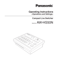
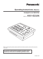
Operating Instructions <Basics> Compact Live Switcher Model No. AW-HS50N Before operating this product, please read the instructions carefully and save this manual for future use. For instructions on how to operate this Compact Live Switcher and how to establish its settings, refer to the “Operations and Settings” manual (PDF file) which can be found on the CD-ROM supplied with the camera. 3TR006512BAA Safety precautions CAUTION: CAUTION TO REDUCE THE RISK OF FIRE OR SHOCK HAZARD AND ANNOYING INTERFERENCE, USE THE RECOMMENDED ACCESSORIES ONLY. RISK OF ELECTRIC SHOCK DO NOT OPEN CAUTION: TO REDUCE THE RISK OF ELECTRIC SHOCK, DO NOT REMOVE COVER (OR BACK). NO USER SERVICEABLE PARTS INSIDE. REFER TO SERVICING TO QUALIFIED SERVICE PERSONNEL. FCC Note: This equipment has been tested and found to comply with the limits for a class A digital device, pursuant to Part 15 of the FCC Rules. These limits are designed to provide reasonable protection against harmful interference when the equipment is operated in a commercial environment. This equipment generates, uses, and can radiate radio frequency energy, and if not installed and used in accordance with the instruction manual, may cause harmful interference to radio communications. Operation of this equipment in a residential area is likely to cause harmful interference in which case the user will be required to correct the interference at his own expense. The lightning flash with arrowhead symbol, within an equilateral triangle, is intended to alert the user to the presence of uninsulated “dangerous voltage” within the product’s enclosure that may be of sufficient magnitude to constitute a risk of electric shock to persons. The exclamation point within an equilateral triangle is intended to alert the user to the presence of important operating and maintenance (service) instructions in the literature accompanying the appliance. WARNING: THIS APPARATUS MUST BE EARTHED Warning: To assure continued FCC emission limit compliance, the user must use only shielded interface cables when connecting to external units. Also, any unauthorized changes or modifications to this equipment could void the user’s authority to operate it. To ensure safe operation, the three-pin plug must be inserted only into a standard three-pin power point which is effectively earthed through the normal household wiring. Extension cords used with the apparatus must have three cores and be correctly wired to provide connection to the earth. Wrongly wired extension cords are a major cause of fatalities. The fact that the apparatus operates satisfactorily does not imply that the power point is earthed or that the installation is completely safe. For your safety, if you are in any doubt about the effective earthing of the power point, please consult a qualified electrician. CAUTION: In order to maintain adequate ventilation, do not install or place this unit in a bookcase, built-in cabinet or any other confined space. To prevent risk of electric shock or fire hazard due to overheating, ensure that curtains and any other materials do not obstruct the ventilation. For CANADA This class A digital apparatus complies with Canadian ICES-003. Cet appareil numérique de la classe A est conforme à la norme NMB-003 du Canada. The socket outlet shall be installed near the equipment and easily accessible or the mains plug or an appliance coupler shall remain readily operable. WARNING: • TO R E D U C E T H E R I S K O F F I R E O R ELECTRIC SHOCK, DO NOT EXPOSE THIS APPARATUS TO RAIN OR MOISTURE. A warning that an apparatus with CLASS 1 construction shall be connected to a MAINS socket outlet with a protective earthing connection. • THE APPARATUS SHALL NOT BE EXPOSED TO DRIPPING OR SPLASHING AND THAT NO OBJECTS FILLED WITH LIQUIDS, SUCH AS VASES, SHALL BE PLACED ON THE APPARATUS. indicates safety information. 2 Safety precautions IMPORTANT SAFETY INSTRUCTIONS Read these operating instructions carefully before using the unit. Follow the safety instructions on the unit and the applicable safety instructions listed below. Keep these operating instructions handy for future reference. 10) Protect the power cord form being walked on or pinched particularly at plugs, convenience receptacles, and the point where they exit from the apparatus. 1) Read these instructions. 2) Keep these instructions. 3) Heed all warnings. 11) Only use attachments/accessories specified by the manufacturer. 4) Follow all instructions. 5) Do not use this apparatus near water. 12) Use only with the cart, stand, tripod, bracket, or table specified by the manufacturer, or sold with the apparatus. When a cart is used, use caution when moving the cart/ apparatus combination to avoid injury from tip-over. 6) Clean only with dry cloth. 7) Do not block any ventilation openings. Install in accordance with the manufacturer’s instructions. 8) Do not install near any heat sources such as radiators, heat registers, stoves, or other apparatus (including amplifiers) that produce heat. 13) Unplug this apparatus during lightning storms or when unused for long periods of time. 9) Do not defeat the safety purpose of the polarized or grounding-type plug. A polarized plug has two blades with one wider than the other. A grounding-type plug has two blades and a third grounding prong. The wide blade or the third prong are provided for your safety. If the provided plug does not fit into your outlet, consult an electrician for replacement of the obsolete outlet. 14) Refer all servicing to qualified service personnel. Servicing is required when the apparatus has been damaged in any way, such as power-supply cord or plug is damaged, liquid has been spilled or objects have fallen into the apparatus, the apparatus has been exposed to rain or moisture, does not operate normally, or has been dropped. indicates safety information. 3 Contents Before use ......................................................... 5 2. Preparations ................................................ 18 Overview ..........................................................................5 2-1. Installation precautions ...........................................18 Concerning the Operating Instructions ............................5 2-2. Connections with other devices...............................19 Trademarks and registered trademarks ...........................5 2-2-1. Block diagram...................................................19 2-2-2. Example of connections ...................................20 About copyright and licence .............................................5 2-3. Turning the unit’s power on and off..........................22 Concerning the ratings display .........................................5 2-4. Checking the video output .......................................22 Disclaimer of warranty ......................................................6 2-4-1. Displaying the OSD menus on a PC monitor ...22 Network security...............................................................6 2-4-2. Displaying the OSD menus on an SDI monitor ............................................23 Characteristics.................................................. 7 2-5. OSD (on-screen display) menu operations .............24 Accessories ...................................................... 9 2-5-1. Displaying and clearing the OSD menus .........24 2-5-2. How to forcibly display the OSD menus ...........24 Required personal computer environment ..... 9 2-5-3. Menu configuration and moving between menus ...................................25 Operating precautions ................................... 10 2-5-4. Operations using the submenus ......................26 1. Parts and their functions ........................... 11 2-5-5. Indications used in this Operating Instructions ......................................27 1-1. Control panel ...........................................................11 2-5-6. Direct operations using the USER buttons and OSD/TIME dial ..........................................28 1-2. Rear panel...............................................................16 2-5-7. Menu delegation function .................................29 2-5-8. Bus status displays ..........................................29 3. Appearance ................................................. 30 4. Specifications ............................................. 31 How the model’s Operating Instructions manuals are configured The manual of this Compact Live Switcher (hereafter, “the unit”) is divided into two manuals: one is the <Basics> (this manual), and the other is the <Operations and Settings> (CD-ROM). Before installing the unit, be sure to read the <Basics> to ensure that the unit is installed correctly. This manual explains how to install the unit, how to check the video outputs and how to perform the OSD menu operations. For details on how to operate the unit and select its settings, refer to the “Operating Instructions <Operations and Settings>” (PDF file) on the CD-ROM supplied with the unit. To read PDF files, you will need Adobe® Reader® which is available from Adobe Systems. 4 Before use Overview Trademarks and registered trademarks This unit is a 1 ME digital video switcher which supports a multiple number of HD and SD formats. Despite its compact size, it comes with four SDI inputs, one DVI-D input, two SDI outputs and one DVI-D output. In addition to its background transition capabilities that use the cut, mix and wipe functions, one keyer channel and one PinP channel are provided to enable video productions in a wide variety of forms. Furthermore, using the multi view display settings, the screen of a monitor can be split into a number of sections to accommodate up to ten images, enabling the number of monitors to be reduced and a space-saving system to be configured at low cost. By means of the IP connection, an operating environment where the unit is tied in with the AW-HE50 HD integrated camera and AW-RP50 remote camera controller is achieved. Microsoft, Windows, Windows Vista, Windows 7 and Internet Explorer are either registered trademarks or trademarks of Microsoft Corporation in the United States and other countries. Intel and Intel Core are trademarks or registered trademarks of Intel Corporation in the United States and other countries. Adobe and Reader are either registered trademarks or trademarks of Adobe Systems Incorporated in the United States and/or other countries. Other names of companies and products contained in these Operating Instructions may be trademarks or registered trademarks of their respective owners. About copyright and licence Distributing, copying, disassembling, reverse compiling, reverse engineering, and also exporting in violation of export laws of the software provided with this unit are expressly prohibited. Concerning the Operating Instructions For the purposes of these instructions, AW-HS50N is referred to as “AW-HS50”. Similarly, AW-HE50HN and AW-HE50SN are referred as “AW-HE50,” and AW-RP50N is referred to as “AW-RP50”. In these instructions, the phrases “pan-tilt head and camera combination” and “camera integrated with a pan-tilt head” are both referred to collectively as “remote camera” except in places where specific equipment is mentioned. Concerning the ratings display The unit’s name, model number and electrical ratings are indicated on its bottom panel. 5 Before use Disclaimer of warranty Network security IN NO EVENT SHALL Panasonic System Networks Co., Ltd. BE LIABLE TO ANY PARTY OR ANY PERSON, EXCEPT FOR REPLACEMENT OR REASONABLE MAINTENANCE OF THE PRODUCT, FOR THE CASES, INCLUDING BUT NOT LIMITED TO BELOW: As you will use this unit connected to a network, your attention is called to the following security risks. Leakage or theft of information through this unit Use of this unit for illegal operations by persons with malicious intent Interference with or stoppage of this unit by persons with malicious intent ANY DAMAGE AND LOSS, INCLUDING WITHOUT LIMITATION, DIRECT OR INDIRECT, SPECIAL, CONSEQUENTIAL OR EXEMPLARY, ARISING OUT OF OR RELATING TO THE PRODUCT; PERSONAL INJURY OR ANY DAMAGE CAUSED BY INAPPROPRIATE USE OR NEGLIGENT OPERATION OF THE USER; UNAUTHORIZED DISASSEMBLE, REPAIR OR MODIFICATION OF THE PRODUCT BY THE USER; INCONVENIENCE OR ANY LOSS ARISING WHEN IMAGES ARE NOT DISPLAYED, DUE TO ANY REASON OR CAUSE INCLUDING ANY FAILURE OR PROBLEM OF THE PRODUCT; ANY PROBLEM, CONSEQUENTIAL INCONVENIENCE, OR LOSS OR DAMAGE, ARISING OUT OF THE SYSTEM COMBINED BY THE DEVICES OF THIRD PARTY; ANY INCONVENIENCE, DAMAGES OR LOSSES RESULTING FROM ACCIDENTS CAUSED BY AN INADEQUATE INSTALLATION METHOD OR ANY FACTORS OTHER THAN A DEFECT IN THE PRODUCT ITSELF; LOSS OF REGISTERED DATA CAUSED BY ANY FAILURE; ANY DAMAGES, CLAIMS, ETC. DUE TO LOSS OR LEAKAGE OF IMAGE DATA OR SETTING DATA SAVED ON THIS UNIT OR IN A PERSONAL COMPUTER. It is your responsibility to take precautions such as those described below to protect yourself against the above network security risks. Use this unit in a network secured by a firewall, etc. If this unit is connected to a network that includes PCs, make sure that the system is not infected by computer viruses or other malicious entities (using a regularly updated antivirus program, anti-spyware program, etc.). Refrain from connections that use public lines. 6 Characteristics Compact design The unit features a compact design with its halfrack size width (210 mm [8-1/4˝]) and its 4RU size (177 mm [6-15/16˝]) depth. The AW-RP50 remote camera controller (option) also has the same size. When it is placed alongside the unit, the two units are housed in the full rack width. Multi view display function One channel is provided for the multi view display function. The user can select whether the screen is to be split into 10, 9, 6, 5 or 4 sections. On each split screen, the user can assign PGM, PVW, AUX or other materials in addition to input materials. Multiple formats supported The signal formats supported by the unit include both HD formats (1080/59.94i, 1080/50i, 1080/24PsF, 1080/23.98PsF, 720/59.94p and 720/50p) and SD formats (480/59.94i and 576/50i). Many different effect functions provided The unit enables the user to select wipe or mix as the type of background transition. A 1-channel keyer function is provided. The user can select linear keys, luminance keys or chroma keys as the key type. One PinP channel and one AUX bus system are available. The user can choose not only cut transitions but also mix transitions as the effect yielded for switching materials using the PinP bus and AUX bus. (Bus transition function) Five input systems and three output systems featured The unit comes with four SDI input connectors (SDI IN 1 to SDI IN 4) and one DVI-D input connector (DVI IN). It also comes with two SDI output connectors (SDI OUT 1 and SDI OUT 2) and one DVI-D output connector (DVI OUT). 2-channel frame memory (8 bits) The user can select the still images stored in the frame memory as the bus material. Still images can be transferred from the host computer, which is connected to the unit via a LAN, to the frame memories. Frame synchronizer system A frame synchronizer is incorporated for each of the inputs so that asynchronous video signals can be selected with no accompanying shocks. Audio level meter display function This function enables the level of the embedded audio signals transferred by SDI input to be displayed. 2-channel up-converter, 4-channel Dot by Dot function and 4-channel video process function An up-converter is incorporated in SDI IN 3 and SDI IN 4. A Dot by Dot function is incorporated for all the SDI input connectors (SDI IN 1 to SDI IN 4). By using this function and the PinP function together, SD materials can be embedded in HD images with no deterioration in the image quality. The video process function is incorporated in all the SDI input connectors (SDI IN 1 to SDI IN 4) to make it possible to adjust the colors at the input stage of the switcher. 7 Characteristics Straightforward and flexible operability The control panel layout includes a row of five crosspoint buttons for the A bus and another row of five crosspoint buttons for the B bus. Using these buttons together with the SHIFT button enables a total of ten images to be switched. Cut switches are also made possible by the CUT button. Separate buttons enable the PinP, KEY and FTB functions to be turned ON or OFF in a single-step action. The slide lever is not only used to initiate background transition operations but it can also be allocated to execute PinP and KEY fade in/out operations. Two USER buttons located on control panel. Using these buttons together with the SHIFT button allows a total of four user settings (USER1 to USER4) to be allocated. PinP settings or WIPE pattern settings can be allocated to the USER buttons. Function for linkup with a remote camera controller using IP connection The unit can be connected to a Panasonic remote camera controller using a network. By linking it with a remote camera controller, it is possible to put together a highly efficient operating environment. Supported remote camera controller: AW-RP50 Only one switcher (the unit) can be linked with a remote camera controller. [Display of camera information] The camera setting information (iris, gain and so on) obtained by the AW-RP50 can be displayed in the AUX output or on the split screens of multi view display. [Transmission of tally information] The unit’s ON AIR tally information can be sent to the AW-RP50. [Switching of materials] The bus materials of the switcher (the unit) can be selected from the AW-RP50. They can be switched in tandem with the selection of the camera using the AW-RP50. (Control buses supported: AUX, PVW, PinP, KEY-F) [Focus assist function] By operating the buttons on the AW-RP50, it is possible to switch to the multi view display screen from the full screen display of the camera images. (Control bus supported: AUX) [Parameter operation using PAN/TILT lever and ZOOM button] The PAN/TILT lever and ZOOM button on the AW-RP50 can be used to change the parameters of the switcher (the unit). On-screen display (OSD) The setting menus can be displayed on an external monitor from the SDI OUT 2 and DVI OUT output connectors. (These menus cannot be displayed using the SDI OUT 1 output connector.) 8 Accessories Check that the following accessories are present and accounted for. Operating Instructions <Basics> (this manual) .......... 1 AC adapter ................................................................ 1 CD-ROM .................................................................... 1 Operating Instructions <Basics> Operating Instructions <Operations and Settings> Data Transmission Software Power cable (2 m [6.6 ft.]) .......................................... 1 Required personal computer environment Run the software that is provided with the switcher on a host computer which satisfies the following specifications. CPU Intel® CoreTM2 DUO 2.4 GHz or faster recommended Memory Windows® XP: 512 MB or more Microsoft® Windows Vista®, Microsoft® Windows® 7: 1 GB or more Network function 10BASE-T or 100BASE-TX Image display function Resolution: 1024 768 pixels or more Color generation: True Color (24 bits or more) Supported operating system Microsoft® Windows® XP, Microsoft® Windows Vista®, Microsoft® Windows® 7 Hard disk drive At least 50 MB of free memory Other CD-ROM drive (for using the Operating Instructions and various software) Adobe® Reader® (for browsing the Operating Instructions on the CD-ROM) 9 Operating precautions In addition to heeding the points presented in the “Safety precautions”, observe the following precautions as well. Precaution to be observed during production This product’s image switching and image effect functions can be used to produce images which flicker rapidly or images which change rapidly. However, bear in mind when using these functions in production that the kinds of images produced may have an adverse effect on the viewer’s physical well-being. Handle carefully. Do not drop the product, or subject it to strong shock or vibration. Do not carry or move the product by the slide lever. This is important to prevent trouble. Use the product in an ambient temperature of 0 °C to +40 °C (32 °F to 104 °F). Avoid using the product at a cold place below 0 °C (32 °F) or at a hot place above +40 °C (104 °F) because extremely low or high temperature will adversely affect the parts inside. When the product is to be discarded When the product is to be discarded at the end of its service life, ask a specialized contractor to dispose of it properly in order to protect the environment. Power off before connecting or disconnecting cables. Before plugging or unplugging the cables, be sure to switch power off. Concerning the consumable parts Cooling fan: This is a consumable part. As a general rule, replace it every 5 years or so (when the unit has been operated for 15 hours a day). Avoid humidity and dust. Avoid using the product at a humid, dusty place because much humidity and dust will cause damage to the parts inside. AC adapter: This is a consumable part. As a general rule, replace it every 5 years or so (when the unit has been operated for 15 hours a day). Maintenance Wipe the product using a dry cloth. To remove stubborn dirt, dip a cloth into a diluted solution of kitchen detergent (neutral), wring it out well, and wipe the product gently. Then, after wiping the product with a moist cloth, wipe it again with a dry cloth. The period when the consumable parts need to be replaced will differ depending on the operating conditions. When the time comes to replace one of these parts, be absolutely sure to ask your dealer to do the job. Caution Avoid using benzine, paint thinners and other volatile fluids. If a chemical cleaning cloth is to be used, carefully read through the precautions for its use. 10 1. Parts and their functions 1-1. Control panel Compact Live Switcher AW-HS50 POWER ALARM LINK USER 1 3 USER 2 4 AUX PinP KEY-F/S BUS DELEGATION MIX WIPE TRANSITION TYPE KEY-S OSD/TIME OSD ON SHIFT PinP ON KEY ON FTB ON A AUX SHIFT PGM PVW KEY OUT CLN MV 1 6 2 7 3 8 4 9 5 10 KEY-F PinP AUX CUT B SHIFT AUTO BKGD POWER indicator [POWER] LINK indicator [LINK] This indicator lights when the POWER switch () on the rear panel is set to ON while power is supplied to the DC IN connector (). This indicator lights when the unit is linked on a network with the AW-RP50 remote camera controller available as an option. The link setting must be enabled at both the unit and AW-HS50. ALARM indicator [ALARM] This indicator lights when the cooling fan () has stopped running, when there is a problem with the power supply (voltage drop) or when the temperature inside the unit has reached an abnormally high level. When this occurs, an alarm message appears on the OSD menu while the OSD menu is displayed on an external monitor (in the OSD ON status). The alarm information can be output to an external device from the unit’s TALLY/GPI connector (). Refer to “5-2. TALLY/GPI” (<Operations and Settings> Operating Instructions). When an alarm has occurred, stop using the unit immediately, and be absolutely sure to contact your dealer. Continuing to use the unit even after an alarm has occurred could damage the unit. 11 1. Parts and their functions USER buttons [USER 1, USER 2] OSD/TIME dial [OSD/TIME] Any four functions selected from among the menu items can be assigned to the USER 1 button and USER 2 button, and then used. The functions registered in [USER1] and [USER3] are assigned to the USER 1 button whereas the functions registered in [USER2] and [USER4] are assigned to the USER 2 button. While the SHIFT button () is held down, the function registered in [USER3] or [USER4] can be selected. Button indicator ON: The functions assigned to the USER buttons are enabled. Button indicator OFF: The functions assigned to the USER buttons are disabled. The following operations are performed using this dial. When the main menu is displayed: Turn the OSD/TIME dial to select a submenu, and press the dial to enter the selection. When a submenu is displayed: Turn the OSD/TIME dial to select a setting item, and press the dial to enter the selection. When the dial is turned while a setting is blinking, the setting changes, and when the dial is pressed, the blinking part moves to the right. When the dial is held down while a setting is blinking, the setting is restored to default value. (However, the network settings are not returned to their default values.) When the dial is turned while it is still held down after the PinP ON, KEY ON, FTB ON or AUTO button has been held down, the respective transition duration can be changed. When “[2] WIPE Menu”, “[3] PinP Menu” or “[5] KEY Adjust Menu” is displayed on the OSD menu or when the chroma key marker is in the ON status, these buttons function as short-cut buttons for specific setting items. Refer to “1-8. Setting the USER buttons” (<Operations and Settings> Operating Instructions). OSD ON button [OSD ON] This selects whether the OSD menu is to be displayed or hidden. Each time the OSD ON button is held down, the OSD menu is switched between displayed and hidden. Button indicator ON: The OSD menu is displayed. Button indicator OFF: The OSD menu is hidden. SHIFT button [SHIFT] This is pressed to call the [USER3] and [USER4] functions which have been assigned to the USER 1 button and USER 2 button or to call the XPT6 to XPT10 materials which have been assigned to crosspoint buttons [1] to [5]. Button indicator ON: The SHIFT button is enabled. Button indicator OFF: The SHIFT button is disabled. (The functions executed using the SHIFT button take effect only while the button is held down.) PinP ON button [PinP ON] This is used to combine PinP (picture-in-picture) images for the transition duration which has been set. Press the button. The button indicator goes off. Images can no longer be combined. Blinks Image combining is now underway. Lights Image combining is now completed. Lights Image combining is now disabled. Press the button. By turning the OSD/TIME dial () while keeping the PinP ON button pressed after the button has been held down, the transition duration can be changed. 12 1. Parts and their functions KEY ON button [KEY ON] AUTO button [BKGD AUTO] This is used to combine key materials for the transition duration which has been set. Press the button. The button indicator goes off. Images can no longer be combined. This automatically initiates the transition for the transition duration which has been set. (Auto transition) Button indicator ON: Auto transition is being executed. Button indicator OFF: Auto transition is complete. If the AUTO button is pressed while auto transition is being executed, the auto transition operation is aborted. When the button is pressed again after the operation was aborted, the remaining transition is executed. When the AUTO button is pressed with the slide lever () at a midway setting, the transition is executed in the remaining time from the midway status. By turning the OSD/TIME dial () while keeping the AUTO button pressed after the button has been held down, the transition duration can be changed. Blinks Image combining is now underway. Lights Image combining is now completed. Lights Image combining is now disabled. Press the button. By turning the OSD/TIME dial () while keeping the KEY ON button pressed after the button has been held down, the transition duration can be changed. FTB ON button [FTB ON] Press this button to fade out the program image to a black screen for the transition duration which has been set. When the button is pressed again, the program image is faded in from the black screen. Press the button. The button indicator goes off. Program image Slide lever This is used when executing transitions manually. When the slide lever is moved to the end, the transition is completed. If it has been moved while an auto transition was being executed, operation will switch to manual as soon as the position of the slide lever has gone beyond the amount of the transition having been executed. It is possible to select a background, key or PinP using a menu for materials involving transitions. Blinks Now fading out. Lights Fade-out is now completed. Lights Now fading in. Press the button. An image other than the black screen can be set as the screen to which the program image is to be faded out. Refer to “1-5. FTB (fade to black)” (<Operations and Settings> Operating Instructions). By turning the OSD/TIME dial () while keeping the FTB ON button pressed after the button has been held down, the transition duration can be changed. CUT button [BKGD CUT] This instantly initiates a transition for the currently selected operation. Button indicator ON: The transition is being executed. Button indicator OFF: The transition is complete. 13 1. Parts and their functions MIX button [MIX] BUS DELEGATION buttons [AUX, PinP, KEY-F/S] This is used to execute transitions (MIX transitions) while overlapping the images of the A bus and B bus (or images of the PGM bus and PST bus). While a transition is being executed, the total of the A bus and B bus (or PGM bus and PST bus) outputs is held at 100 %. When the MIX button is pressed, its indicator lights to show that this function is now selected. If the WIPE button () is now pressed, the function selection is released, and the indicator goes off. Button indicator ON: A MIX transition is being selected. These are used to select the buses which output the materials selected by the crosspoint buttons (, ). Any of four lighting statuses are established: the status in which the indicators of all of the three buttons are off, and the statuses in which the indicator of one of the buttons is blinked. (It is not possible for the indicators of two of the buttons to be blinked at the same time.) When one of the buttons is pressed while the indicators of all three buttons are off, the indicator of the pressed button blinks. When the button whose indicator is blinked is pressed, its indicator is turned off. When a button whose indicator is not blinked is pressed, only the indicator of the pressed button blinks. WIPE button [WIPE] This is used to execute transitions using the selected wipe pattern. When the WIPE button is pressed, its indicator lights to show that this function is now selected. If the MIX button () is now pressed, the function selection is released, and the indicator goes off. By turning the OSD/TIME dial () after the WIPE button has been held down and while the button is still pressed, the wipe pattern can be changed. Button indicator ON: Wipe selection underway The following operations can be undertaken in each of these statuses. 1. When the indicators of all three buttons are off: In this status, the materials of the bus that executes background transitions are selected. 2. When the indicator of the AUX button is blinked: In this status, the AUX bus materials are selected. Bus tally indicators [A, B] The indicator corresponding to the bus whose program (PGM) materials are being output lights. 3. When the indicator of the PinP button is blinked: In this status, the PinP bus materials are selected. 4. When the indicator of the KEY-F/S button is blinked: In this status, the key fill bus and key source bus materials are selected. 14 1. Parts and their functions A bus crosspoint buttons [1 to 5] B bus crosspoint buttons [1 to 5] 2. When the indicator of the AUX button is blinked: When one of the crosspoint buttons is pressed, the AUX bus material is selected. These are used to select the materials to be output to the PGM bus, PST bus, AUX bus, PinP bus and KEY-F/S bus. When a button is pressed and the material allocated to that button is selected, the indicator of the button lights. [B bus crosspoint buttons] When a button from [1] to [5] is pressed, the material assigned to the corresponding XPT1 to XPT5 is selected. When a button from [1] to [5] is pressed while the SHIFT button is held down, the material assigned to the corresponding XPT6 to XPT10 is selected. Depending on the status of the BUS DELEGATION button () indicators, the operation performed differs as follows. [A bus crosspoint buttons] When a button from [1] to [5] is pressed, PGM, PVW, KEY OUT, CLN or MV is selected respectively. 1. While the indicators of all three buttons are off: When one of the crosspoint buttons is pressed, the materials of the buses which execute the background transitions are selected. 3. While the indicator of the PinP button is blinked: When a B crosspoint button is pressed, the PinP bus material is selected. [B bus crosspoint buttons] These are used to select the PST bus materials. When a button from [1] to [5] is pressed, the material assigned to the corresponding XPT1 to XPT5 is selected. When a button from [1] to [5] is pressed while the SHIFT button is held down, the material assigned to the corresponding XPT6 to XPT10 is selected. [B bus crosspoint buttons] When a button from [1] to [5] is pressed, the material assigned to the corresponding XPT1 to XPT5 is selected. When a button from [1] to [5] is pressed while the SHIFT button is held down, the material assigned to the corresponding XPT6 to XPT10 is selected. [A bus crosspoint buttons] These are used to select the PGM bus materials. When a button from [1] to [5] is pressed, the material assigned to the corresponding XPT1 to XPT5 is selected. When a button from [1] to [5] is pressed while the SHIFT button is held down, the material assigned to the corresponding XPT6 to XPT10 is selected. 4. While the indicator of the KEY-F/S button is blinked: When one of the crosspoint buttons is pressed, the key fill bus or key source bus material is selected. [B bus crosspoint buttons] These are used to select the key fill bus materials. When a button from [1] to [5] is pressed, the material assigned to the corresponding XPT1 to XPT5 is selected. When a button from [1] to [5] is pressed while the SHIFT button is held down, the material assigned to the corresponding XPT6 to XPT10 is selected. Memo Using the OSD menu, A/B, PGM(A)/PST(B) or PGM(B)/PST(A) can be selected as the bus mode. The description given above applies when the PGM(A)/PST(B) has been selected. Refer to “1-1-4. Selecting the bus mode” (<Operations and Settings> Operating Instructions). [A bus crosspoint buttons] These are used to select the key source bus materials. When a button from [1] to [5] is pressed, the material assigned to the corresponding XPT1 to XPT5 is selected. When a button from [1] to [5] is pressed while the SHIFT button is held down, the material assigned to the corresponding XPT6 to XPT10 is selected. 15 1. Parts and their functions 1-2. Rear panel " $ SIGNAL GND 4 1 2 SDI OUT 1 3 2 POWER ON SDI IN 4 3 1 2 12 V TALLY / GPI DVI OUT DVI IN IN LAN BOOT ! SV NM # SDI IN connectors [SDI IN 1 to 4] POWER switch [POWER] These are the HD/SD SDI signal input connectors. The following input modes can be set by menu operations: SDI IN 1, 2: Normal, DbyD SDI IN 3, 4: Normal, DbyD, UC, Auto The video process function can be used for all the SDI IN 1 to 4 input signals. The up-converter cannot be used for SDI IN 1 and 2. When signals differing from the system format have been input, they are replaced with black signals. (However, when HD has been selected as the system format setting and DbyD or UC has been selected as the input mode setting, SD signals with the same vertical frequency can be input.) When the POWER switch is set to the ON position, the POWER indicator () lights, and the unit can be operated. SDI OUT connectors [SDI OUT 1, 2] These are the HD/SD SDI signal output connectors. The following signals can be assigned to the connector by menu operations: PGM, PVW, CLN, AUX, MV, KEYOUT At the SDI OUT 1 connector, the output signals are split into two and output through two connectors. It is the same signal that is output. The OSD menu, multi view display frame, tally information, names of the materials and audio level meters are not displayed for the signals of the SDI OUT 1 connector. When the high-resolution multi view mode is enabled, it is not possible to assign MV signals. DVI IN connector [DVI IN] This is the DVI-D signal input connector. Signals with the following resolution can be input to this connector. Digital RGB (vertical frequency: 60 Hz): XGA (1024 768), WXGA (1280 768), SXGA (1280 1024), WSXGA+ (1680 1050), UXGA (1600 1200), WUXGA (1920 1200) Digital RGB: 1920 1080/50p, 1920 1080/59.94p Analog signals cannot be input to this connector. A DVI-I cable cannot be used. 16 1. Parts and their functions DVI OUT connector [DVI OUT] TALLY/GPI connector [TALLY/GPI] (D-sub 15-pin, female, inch thread) This is the DVI-D signal output connector. Signals with the following resolution can be output from this connector by menu operations. This connector features five contact input ports for controlling the unit from an external device and seven open collector output ports for outputting the tally information and alarm information from the unit. Digital RGB (vertical frequency: 60 Hz): XGA (1024 768), WXGA (1280 768), SXGA (1280 1024), WSXGA+ (1680 1050), UXGA (1600 1200), WUXGA (1920 1200) Cooling fan Digital RGB: 1920 1080/50p, 1920 1080/59.94p DC IN connector [12V Furthermore, the following signals can be assigned by menu operations. IN] (DC 12 V, 2.0 A) The AC adapter provided with the unit is connected to this connector. PGM, PVW, CLN, AUX, MV, KEYOUT Ground terminal [SIGNAL GND] The connector supports the high-resolution multi view mode so that images can be output at a high resolution when SD has been selected as the system format. Analog signals cannot be output from this connector. A DVI-I cable cannot be used. When the high-resolution multi view mode has been enabled, MV signals are assigned to the DVI OUT connector, and they cannot be assigned to the SDI OUT 1 connector or SDI OUT 2 connector. Connect this to the system’s ground. SERVICE switch [SV/NM] This switch is used for maintenance purposes. For normal operations, select the “NM” position. Wire fastening fitting An anti-theft wire available on the market can be fastened to this fitting to prevent theft. LAN connector [LAN] (RJ-45) (10BASE-T/100BASE-TX) The remote camera, remote camera controller and host computer supporting IP connections to this LAN connector are connected using LAN cables. When a device is connected directly to the unit, use a crossover cable (category 5 or above). When a device is to be connected to the unit through a hub (switching hub), for instance, use a straight cable (category 5 or above). 17 2. Preparations 2-1. Installation precautions In addition to heeding the points presented in the “Safety precautions”, observe the following precautions as well. Be absolutely sure to ask your dealer to do the jobs of installing and connecting the unit. Connecting the power supply Handle carefully! Use within AC 100 V to 120 V. Be absolutely sure to use only the power cable and AC adapter supplied with the unit. The power cable supplied with the unit has a 3-pin plug with a grounding terminal. Connect it to a 3-pole outlet which has been connected to ground. Be absolutely sure to connect the ground terminal (SIGNAL GND) at the rear of the unit to the system ground. Insert the DC plug as far as it will go until it locks into position. When the unit is not going to be used for a prolonged period of time, turn off its power, and disconnect the power plug from the AC outlet. Dropping the unit or subjecting it to strong impact or vibration may cause trouble and/or malfunctioning. 4 1 SDI IN 3 2 3 2 Do not allow any foreign objects to enter inside the unit! Allowing water, metal items, scraps of food or other foreign objects inside the unit may cause a fire and/ or electric shocks. Choosing the best installation location This unit is designed for indoor use only. Install the unit on a sufficiently strong, stable and level surface for use. Ensure a space of at least 100 mm (3-15/16˝) around the front and rear vents to avoid obstructing ventilation. In particular, ensure sufficient space between ventilation and wiring when using mounted in a panel or table. Do not install the unit in a manner in which its cables and other accessories can be easily damaged. Do not install the unit in a cold place where the temperatures will drop below 0 °C (32 °F) or in a hot place where the temperatures will rise above +40 °C (104 °F). Avoid installing the unit where it will be exposed to direct sunlight or to the hot air that is blown out from other products. Installing the unit in a very humid, dusty or vibration-prone location may give rise to trouble. POWER ON 1 12V IN BOOT M SV N Ventilation holes 18 2. Preparations 2-2. Connections with other devices 2-2-1. Block diagram AW-HS50 SDI IN 1 SDI IN 2 INPUT 1 to 4 (SDI) SDI IN 3 DbyD DbyD DbyD UC FS VPrc FS VPrc FS VPrc BLACK COLOR BAR KEY (LIN, LUM, CHROMA) FMEM 1 PinP FMEM 2 SDI IN 4 DbyD UC FS VPrc IN MTX INPUT 5 (DVI-D) DVI IN Scaler SDI OUT 1 41, 42 BKGD TRANS (CUT, MIX, WIPE) COLOR BKGD FS Output 1, 2 (SDI) OSD OUT MTX SDI OUT 2 MV Frame FTB MV Tally AUX Src Name MULTI VIEW Audio Level Meter DVI OUT Output 3 (DVI-D) Scaler Power DC IN 12 V TALLY/GPI (D-sub, 15-pin) LAN (RJ45) 43 Power cable AC adapter [Output, 7 pin] (1) TALLY OUT 1 (2) TALLY OUT 2 (3) TALLY OUT 3 (4) TALLY OUT 4 (5) TALLY OUT 5 (6) ALARM (7) KEY ON [Input, 5 pin] (10) TALLY DISABLE (11) AUTO (12) CUT (13) KEY ON (14) PinP ON Hub 44 45 AW-RP50 45 AW-HE50 45 PC (15) GND 1: At the SDI OUT 1 connector, the output signals are split into two and output through two connectors. 2: The setting menus (OSD), multi view display frame, tally information, names of the materials and audio level meters are not displayed for the signals of the SDI OUT 1 connectors. 3: Use a crossover cable when connecting the unit and another device on a 1:1 basis without going through a hub (switching hub). 4: Use a switching hub. 5: Communication over the internet is not possible. 19 2. Preparations 2-2-2. Example of connections HD SDI HD camera HD SDI 42 SDI monitor HD SDI HD SDI HD camera 42 VTR HD SDI HD camera HD SDI SD SDI SDI monitor SD camera DVI-D 44 DVI-D 43 PC monitor PC 41 SIGNAL GND 4 1 2 SDI OUT 1 3 2 POWER ON SDI IN 4 3 1 2 12 V TALLY / GPI DVI OUT DVI IN IN LAN BOOT SV NM AC adapter Compact Live Switcher AW-HS50 Power cable 1: The up-converter works only with the SDI IN 3 and SDI IN 4 inputs. (The Dot by Dot mode works with all four SDI IN 1 to 4 inputs.) 2: The two signals which are output from the SDI OUT 1 connectors are identical. The OSD menus, multi view display frame, tally information, names of the materials and audio level meters are not displayed for the signals of these connectors. 3: Analog signal input is not supported. 4: Analog signal output is not supported. 20 2. Preparations Example of IP connections (connecting the unit to the AW-HE50 and AW-RP50) AW-HE50S SDI video signal AW-HE50S LAN cable (straight cable) Monitor 2 Switching hub Monitor 1 LAN cable (straight cable) Monitor Monitor AW-HS50 AW-RP50 21 2. Preparations 2-3. Turning the unit’s power on and off 2-4. Checking the video output Described below are the steps taken to display the unit’s OSD menu on an external monitor to check the unit’s video output. Turning on the power 1 2-4-1. Displaying the OSD menus on a PC monitor Set the POWER switch to the ON position. When power is supplied to the unit, the POWER indicator lights up green. 1 Turning off the power 1 Set the POWER switch to the OFF position. The unit’s power is turned off, and the POWER indicator goes off. Connect the PC monitor to the unit’s DVI OUT connector. 2 Turn on the power of the PC monitor. 3 Turn on the power of the unit. 4 Hold down the OSD ON button. The OSD ON button indicator lights, and the OSD menus are displayed on the PC monitor. If the OSD menus do not appear on the monitor, refer to “2-5-2. How to forcibly display the OSD menus”. Note If the OSD menu fails to appear on the PC monitor even after the above steps have been taken, it may mean that the PC monitor does not support the unit’s DVI output format. Check the input specifications of the PC monitor. 22 2. Preparations Changing the video format 2-4-2. Displaying the OSD menus on an SDI monitor 1 If the OSD menus cannot be displayed even when the SDI monitor has been connected to the unit, the video format must be changed. Follow the steps below to change the video format. If the OSD menus can be displayed using a PC monitor, change the video format by following the steps in “4-1-1. Setting the video format” (<Operations and Settings> Operating Instructions). Connect the SDI monitor to the unit’s SDI OUT 2 connector. 2 Turn on the power of the SDI monitor. 3 Turn on the power of the unit. 4 Hold down the OSD ON button. 1 The OSD ON button indicator lights, and the OSD menus are displayed on the SDI monitor. If the OSD menus do not appear on the monitor, refer to “2-5-2. How to forcibly display the OSD menus”. 2 Notes Turn off the power of the unit. Turn on the unit’s power while at the same time holding down the button that corresponds to the video format supported by the SDI monitor. Button to press at the same time The OSD menus cannot be output from the SDI OUT 1 connector. If the OSD menu fails to appear on the SDI monitor even after the above steps have been taken, it may mean that the video format which has been set in the unit is not the correct one. Take the steps in the next section to change the unit’s video format. Refer to “Changing the video format”. 3 Video format [OSD ON] + A bus crosspoint [1] 1080/59.94i [OSD ON] + A bus crosspoint [2] 1080/50i [OSD ON] + A bus crosspoint [3] 720/59.94p [OSD ON] + A bus crosspoint [4] 720/50p [OSD ON] + A bus crosspoint [5] 1080/24PsF [OSD ON] + B bus crosspoint [1] 1080/23.98PsF [OSD ON] + B bus crosspoint [2] 480/59.94i [OSD ON] + B bus crosspoint [3] 576/50i Hold down the OSD ON button. The OSD ON button indicator lights, and the OSD menus are displayed on the SDI monitor. Note If the OSD menu fails to appear on the SDI monitor even after the above steps have been taken, it may mean that the SDI monitor does not support the unit’s SDI output format. Check the input specifications of the SDI monitor. 23 2. Preparations Changing the connector for outputting the OSD menus 2-5. OSD (on-screen display) menu operations =?1RGTCVKQP/GPW The unit’s settings are selected using the OSD menus which are displayed on the external monitor. Described here is how to operate the OSD menus. 15&176 15&5K\G 15&$CEM -G[2TKQTKV[ $WU/QFG 6KOG7PKV 5NKFG.GXGT )2++PRWV )2+1WVRWV %CO%QPV.KPM 5;56'//GPW 2-5-1. Displaying and clearing the OSD menus Basic operations When the OSD ON button is held down, the OSD ON button indicator lights, and the OSD menus are displayed on the external monitor. When the OSD ON button is held down while an OSD menu is displayed, the OSD ON button indicator goes off, and the OSD menu display is cleared. 5&+176 &8+176 (7.. 1P 2KP2QXGT-'; 2)/ # 256 $ 5GE $-)& 'PCDNG 'PCDNG 1HH 7PNQEMGF The OSD menu output connector can be changed using the “1. OSD OUT” item on the [13] Operation Menu. SDI-OUT2: The menus are output from the SDI OUT 2 connector. DVI-OUT: The menus are output from the DVI OUT connector. SDI-OUT2+DVI-OUT: The menus are output from both the SDI OUT 2 connector and DVI OUT connector. Note If parts of the OSD menus overlap the multi view display frame, the split screen frames and characters will not be displayed. Note The OSD menus cannot be output from the SDI OUT 1 connector. 2-5-2. How to forcibly display the OSD menus When the OSD ON button is held down while holding down the SHIFT button, the following settings are established automatically. The OSD ON button indicator lights, and the OSD menus are displayed on the external monitor. The output destination of the OSD menus is set to both the SDI OUT 2 connector and DVI OUT connector. The screen size of the OSD menus output from the DVI OUT connector is set to Auto. (The menus are output in the size that corresponds to the input specifications of the PC monitor which is connected to the unit.) 24 2. Preparations 2-5-3. Menu configuration and moving between menus Menu configuration of the unit Moving between the main menu and submenus The unit’s OSD menus are organized in two hierarchical levels: the main menu and the submenus. Moving from the main menu to a submenu To select a submenu item: Turn the OSD/TIME dial to select an item. Entering the setting selected for the submenu item: Press the OSD/TIME dial to enter the selected item’s setting. Main menu: This lists the submenu items. Submenu: This displays the setting items and the settings. The settings can be changed on this screen. Moving from a submenu to the main menu The main menu is restored to the screen when the OSD ON button is pressed. #9*5/CKP/GPW Main menu =?6+/'%$)&/GPW =?9+2'/GPW =?2KP2/GPW =?-';5GVWR/GPW =?-';#FLWUV/GPW =?%JTQOC-G[/GPW =?/WNVK8KGY2CVVGTP/GPW =?/WNVK8KGY1WV(TCOG/GPW =?:2659#UUKIP/GPW Ť 72256722567225672256 Turn the OSD/TIME dial, and select the submenu item. Press the OSD/TIME dial to enter the selected item’s setting. Submenu items Statuses of the USER buttons Press the OSD ON button. =?6+/'%$)&/GPW Submenu Setting items #7616KOG U^H 2KP26KOG U^H -';6KOG U^H (6$6KOG U^H (6$5QWTEG $NCEM #7:$756TCPU U^H^&KUCDNG 2KP2$756TCPU U^H^&KUCDNG 2KP2'((&5.8 U^H^&KUCDNG 5GV%$)&%QN 9JKVG Ť 72256722567225672256 USER button status display Settings Statuses of the USER buttons Displaying menus consisting of more than one page The functions assigned to USER buttons 1 to 4 are displayed on the last line of each menus screen. Refer to “1-8. Setting the USER buttons” (<Operations and Settings> Operating Instructions). When a menu contains many setting items, they are displayed on more than one page. When “” or “” is displayed, turn the OSD/TIME dial on the line before the arrow to scroll the screen and display the items which are hidden. In this manual, only one menu screen is shown even when that screen consists of more than one page. In this manual, the menu screens are always shown without the area where the USER button statuses are displayed except under special circumstances. 25 2. Preparations 2-5-4. Operations using the submenus 1 Select the line with the setting item. When the OSD/TIME dial is turned, the cursor “>” at the far left moves up or down. Bring the cursor to the line with the setting item whose setting is to be changed, and then press the OSD/TIME dial. The cursor “>” now moves to the center where the setting can be changed. The value to be set now blinks. =?9+2'/GPW Turn the OSD/TIME dial, and select the item. 2 &KTGEVKQP $QTFGT5QHV 5GV$QTFGT%QN #FL$QTFGT%QN 2QUKVKQP 5GV6Q2TGUGV 04 $^5 ▼ ▼ ▼ 9JKVG ▼ *^5^. :^;^ ▼ ▼ &KTGEVKQP 04 $QTFGT5QHV $^5 5GV$QTFGT%QN 9JKVG #FL$QTFGT%QN :^;^ *^5^. 2QUKVKQP :^;^ 5GV6Q2TGUGV 2CVVGTP ▼ ▼ ▼ Press the OSD/TIME dial to enter the item. ▼ 2CVVGTP =?9+2'/GPW The value to be set now blinks. Change the setting. While the setting is blinking, turn the OSD/TIME dial. The setting in the blinking part now changes. If a value has up to two decimal places, the speed at which the setting is changed can be increased by turning the OSD/TIME dial while the SHIFT button is held down. Memo When values are changed for the regular setting items, these changes are reflected straight away but, with some of the setting items (such as Format), the changes will not be reflected unless the OSD/TIME dial is pressed once the changes have been made. An asterisk () appears in front of the currently selected settings to identify these items. =?9+2'/GPW =?9+2'/GPW 2CVVGTP &KTGEVKQP $QTFGT5QHV 5GV$QTFGT%QN #FL$QTFGT%QN 2QUKVKQP 5GV6Q2TGUGV 04 $^5 ▼ ▼ ▼ 9JKVG ▼ *^5^. :^;^ &KTGEVKQP $QTFGT5QHV 5GV$QTFGT%QN #FL$QTFGT%QN 2QUKVKQP 5GV6Q2TGUGV 04 $^5 ▼ ▼ ▼ 9JKVG ▼ *^5^. :^;^ 26 ▼ ▼ ▼ ▼ ▼ ▼ [Returning the setting to its default value] When the OSD/TIME dial is held down now, the value is returned to its default value. ▼ ▼ ▼ Turn the OSD/TIME dial to change the setting that is now blinking. ▼ This part blinks. ▼ ▼ 2CVVGTP 2. Preparations 3 Move the blinking part. When a setting item has a multiple number of settings, press the OSD/TIME dial to move the blinking part to the right. =?9+2'/GPW =?9+2'/GPW 2CVVGTP &KTGEVKQP $QTFGT5QHV 5GV$QTFGT%QN #FL$QTFGT%QN 2QUKVKQP 5GV6Q2TGUGV 04 $^5 ▼ ▼ ▼ 9JKVG ▼ *^5^. :^;^ &KTGEVKQP $QTFGT5QHV 5GV$QTFGT%QN #FL$QTFGT%QN 2QUKVKQP 5GV6Q2TGUGV 04 $^5 ▼ ▼ ▼ 9JKVG ▼ *^5^. :^;^ ▼ ▼ ▼ ▼ ▼ ▼ ▼ ▼ ▼ 4 ▼ This part blinks. ▼ ▼ 2CVVGTP The blinking part moves to the right. Press the OSD/TIME dial. Complete the changes. When the OSD ON button is pressed while a setting is blinking, the cursor “>” moves to the far left, and the status for selecting the line with a setting item is restored. =?9+2'/GPW =?9+2'/GPW 2CVVGTP &KTGEVKQP $QTFGT5QHV 5GV$QTFGT%QN #FL$QTFGT%QN 2QUKVKQP 5GV6Q2TGUGV 04 $^5 ▼ ▼ ▼ 9JKVG ▼ *^5^. :^;^ &KTGEVKQP $QTFGT5QHV 5GV$QTFGT%QN #FL$QTFGT%QN 2QUKVKQP 5GV6Q2TGUGV 04 $^5 9JKVG *^5^. :^;^ ▼ ▼ ▼ 2CVVGTP ▼ ▼ ▼ This part blinks. Press the OSD ON button. Furthermore, the “>” cursor will move to the far left, and the status for selecting the line to be set will be restored also when the OSD/TIME dial has been pressed while the blinking part is at the far right. 2-5-5. Indications used in this Operating Instructions The operations for the setting items are indicated in this Operating Instructions as shown below. Example: When operating the “5. Adj Border Col” item on the [2] WIPE Menu. Submenu Setting item [2] WIPE Menu 5. Adj Border Col 27 2. Preparations 2-5-6. Direct operations using the USER buttons and OSD/TIME dial The functions that have been assigned to the USER buttons are displayed in the USER button status display area, and the setting itemes which can be operated directly using the USER buttons and OSD/TIME dial are displayed in the states listed below. When this happens, the functions assigned to the USER buttons are disabled. When the chroma key marker is displayed When the submenu [2] WIPE Menu is displayed When the submenu [3] PinP Menu is displayed When the submenu [5] KEY Adjust Menu is displayed When a particular USER button is pressed at this time, the status in which to change the settings shown in the status area is established, and the value concerned can be changed by turning the OSD/TIME dial. The values that have been changed are reflected instantly. U1: USER 1 button U2: USER 2 button U3: USER 3 button (SHIFT button + USER 1 button) U4: USER 4 button (SHIFT button + USER 2 button) Example: When [2] WIPE Menu is displayed The value of “B” for the 3. Border/Soft item has been set. The “B” value is blinking. =?9+2'/GPW 2CVVGTP Turn the OSD/TIME dial to change the value. $^5 9JKVG *^5^. :^;^ =?9+2'/GPW ▼ ▼ ▼ ▼ ▼ ▼ ▼ ▼ ▼04 ▼ &KTGEVKQP $QTFGT5QHV 5GV$QTFGT%QN #FL$QTFGT%QN 2QUKVKQP 5GV6Q2TGUGV 72QU:72QU;77 2CVVGTP &KTGEVKQP $QTFGT5QHV 5GV$QTFGT%QN #FL$QTFGT%QN 2QUKVKQP 5GV6Q2TGUGV 04 $^5 9JKVG *^5^. :^;^ Press the USER 1 button. 72QU:72QU;77 The indicator of the USER 1 button lights. The “X” value is changed, and it is reflected instantly. The value stops blinking. The cursor moves to the last line that displays the USER button status. =?9+2'/GPW 2CVVGTP &KTGEVKQP $QTFGT5QHV 5GV$QTFGT%QN #FL$QTFGT%QN 2QUKVKQP 5GV6Q2TGUGV 04 $^5 9JKVG *^5^. :^;^ Press the USER 1 button. 72QU:72QU;77 The state in which the value (Pos-X) of “X” for the 6. Position item can be changed is now established. =?9+2'/GPW 2CVVGTP &KTGEVKQP $QTFGT5QHV 5GV$QTFGT%QN #FL$QTFGT%QN 2QUKVKQP 5GV6Q2TGUGV 04 $^5 9JKVG *^5^. :^;^ 72QU:72QU;77 The USER 1 button indicator goes off, the direct operation is canceled, and operation returns to the 3. Border/Soft item setting. 28 2. Preparations 2-5-7. Menu delegation function When the buttons listed below are double-clicked, the specified menu is selected. (The menu delegation function) The operation corresponding to the button pressed is also executed. <List of menu delegation functions> Button Menu selected AUTO FTB ON [1] TIME/CBGD Menu KEY ON PinP ON WIPE [2] WIPE Menu PinP [3] PinP Menu KEY-F/S When any key type except “Chroma” has been selected: [4] KEY Setup Menu When “Chroma” has been selected as the key type: [6] ChromaKey Menu USER 1 USER 2 USER 3 (SHIFT + USER 1) [12] USER/FMEM Menu USER 4 (SHIFT + USER 2) 2-5-8. Bus status displays When the A bus or B bus crosspoint buttons are held down, the BUS Assign Status menu appears for the OSD menu. POWER ALARM LINK USER 1 3 USER 2 4 SHIFT OSD/TIME OSD ON $75#UUKIP5VCVWU AUX PinP KEY-F/S BUS DELEGATION MIX WIPE TRANSITION TYPE KEY-S PinP ON KEY ON :2659 :2659#UKIP 5&++0 +0276 2)/ 5&++0 +0276 289 5&++0 +0276 #7: /8 2KP2 5&++0 +0276 -';(KNN %$)& -';5QWTEG (/'/ FTB ON A AUX SHIFT KEY-F PinP AUX PGM PVW KEY OUT CLN MV 1 6 2 7 3 8 4 9 5 10 CUT B SHIFT AUTO BKGD 29 3. Appearance Unit: mm (inch) 189 (7-7/16) SV NM BOOT DVI OUT TALLY / GPI DVI IN LAN 12 V 2 4 SDI OUT 1 3 IN 1 2 SDI IN 1 4 3 2 ON POWER SIGNAL GND 67 (2-5/8) Compact Live Switcher AW-HS50 177 (6-15/16) POWER AUX ALARM LINK PinP KEY-F/S BUS DELEGATION USER 1 3 USER 2 4 MIX WIPE TRANSITION TYPE KEY-S SHIFT OSD/TIME OSD ON PinP ON KEY ON FTB ON A AUX SHIFT PGM PVW KEY OUT CLN MV 1 6 2 7 3 8 4 9 5 10 KEY-F PinP AUX CUT B SHIFT AUTO BKGD 53 (2-1/16) 210 (8-1/4) 30 4. Specifications Inputs 5 video lines SDI 4 signal lines: SDI IN 1 to SDI IN 4 DVI-D 1 signal line: DVI IN Outputs 3 video lines, 4 outputs SDI 2 signal lines: SDI OUT 1, SDI OUT 2 (Only the SDI OUT 1 signals are split into two) DVI-D 1 signal line: DVI OUT Signal formats SD 480/59.94i, 576/50i HD 1080/59.94i, 1080/50i, 720/59.94p, 720/50p, 1080/24PsF, 1080/23.98PsF Signal processing Y:Cb:Cr 4:2:2, 10 bit (8 bits for frame memory) RGB 4:4:4, 8 bit ME number 1ME SDI inputs HD: Serial digital component (SMPTE 292M) SD: Serial digital component (SMPTE 259M) 4 signal lines: SDI IN 1 to SDI IN 4 HD: SMPTE 292M (BTA S-004B) standard complied with • 0.8 V [p-p] 10 % (75 ) • Input return loss More than 15 dB (5 MHz to 1.5 GHz) • Automatic equalizer 100 m (328 ft.) (when 5C-FB cable is used) SD: SMPTE 259M standard complied with • 0.8 V [p-p] 10 % (75 ) • Input return loss More than 15 dB (5 MHz to 270 MHz) • Automatic equalizer 200 m (656 ft.) (when 5C-2V cable is used) DVI-D input Digital RGB (Vertical frequency: 60 Hz): XGA (1024 768), WXGA (1280 768), SXGA (1280 1024), WSXGA+ (1680 1050), UXGA (1600 1200), WUXGA (1920 1200) Digital RGB: 1080/50p, 1080/59.94p Analog input signals are not supported. 31 4. Specifications SDI outputs HD: Serial digital component (SMPTE 292M) SD: Serial digital component (SMPTE 259M) 2 signal lines: SDI OUT 1, SDI OUT 2 (Only the SDI OUT 1 signals are split into two) HD: SMPTE 292M (BTA S-004B) standard complied with • Output return loss More than 15 dB (5 MHz to 1.5 GHz) • Output level 0.8 V [p-p] 10 % (75 ) • Rise time Less than 270 ps • Fall time Less than 270 ps • Difference between rise time and fall time Less than 100 ps • Alignment jitter Less than 0.2 UI (130 ps) • Timing jitter Less than 1.0 UI • Eye aperture ratio More than 90 % • DC offset 0 0.5 V SD: SMPTE 259M standard complied with • Output return loss More than 15 dB (5 MHz to 270 MHz) • Output level 0.8 V [p-p] 10 % (75 ) • Rise time Less than 1.5 ns • Fall time Less than 1.5 ns • Difference between rise time and fall time Less than 0.5 ns • Jitter Less than 0.2 UI DVI-D output Digital RGB (Vertical frequency: 60 Hz): XGA (1024 768), WXGA (1280 768), SXGA (1280 1024), WSXGA+ (1680 1050), UXGA (1600 1200), WUXGA (1920 1200) Digital RGB: 1080/50p, 1080/59.94p High-resolution multi view mode supported: Signals are also output with a high resolution even when SD has been selected as the system mode. When the high-resolution multi view mode is enabled, MV is assigned to the DVI OUT connector, and MV cannot be assigned to the SDI OUT 1 connectors or SDI OUT 2 connector. Analog output signals are not supported. Video delay time 1 frame (F) Video signals that have passed through the PinP, multi view display, DVI-D input or DVI-D output will be delayed in each case by up to one frame. 32 4. Specifications Control I/O LAN (RJ-45) 10BASE-T/100BASE-TX (For IP control) Connecting cable: LAN cable (category 5 or above), max. 100 m [328 ft.], STP (Shielded Twisted Pair) cable recommended When connecting to a hub (switching hub), use a straight cable. Use a crossover cable when connecting the unit and another device on a 1:1 basis without going through a hub. TALLY/GPI (D-sub 15-pin, female, inch thread) INPUT : 5 inputs, photocoupler sensing OUTPUT : 7 outputs, open collector output (negative logic) Other SERVICE switch [SV/NM] (for maintenance purposes) Normally, this switch is used as the “NM” position. Ambient operating temperature 0 °C to 40 °C (32 °F to 104 °F) Humidity 10 % to 90 % (no condensation) Power requirements DC 12 V 10 % (AC adapter provided) Current consumption 2.0 A (DC 12 V) Dimensions (W H D) 210 67 177 mm (8-1/4˝ 2-5/8˝ 6-15/16˝) [excluding protrusions] Mass 1.4 kg (3.08 lbs.) Supplied AC adapter Rated input: AC 100 V to 240 V, 1.3 A, 47 Hz to 63 Hz Rated output: DC 12 V, 3.5 A, 42 W The provided power cable is for 125 V AC or less. Use it within AC 100 V to 120 V. The AC adapter and power cable provided must be used without fail. Mass and dimensions shown are approximate. Specifications are subject to change without notice. 33 © Panasonic System Networks Co., Ltd. 2010 F0610Y1070 D