1
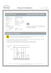
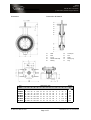
VB-W Issue: 6.1 Date Of Issue: 23/12/2010 © 2010 Sontay Limited. All rights reserved. Butterfly Valves Features Specification Flangeless wafer, rubber lined Function Isolating or regulating Installation Clamping between two flanges To suit flanges PN6, PN10, PN16 VB-W50 50mm Butterfly valve VB-W65 65mm Butterfly valve Valve shut-off pressures: VB-W80 6 bar 80mm Butterfly valve 10 bar VB-W100 16 bar 100mm Butterfly valve Standard Materials: VB-W125 Body Cast iron GG25 Disc S/S 431 Shaft S/S 431 Pin S/S 431 Lining 125mm Butterfly valve VB-W150 150mm Butterfly valve VB-W200 EPDM (-40 to +110°C) 200mm Butterfly valve Water, weak acids Leakage: Linkages: Standard Tight shut-off @ 16 bar Undercut Tight shut-off @ 6 bar Country of origin Tight shut-off Product Codes Type Media type Range of linings for different applications VB-LK1 Netherlands 50 to 80mm, 16Nm actuator linkage VB-LK2 100 to 125mm, 16 to 62Nm actuator linkage VB-LK3 50 to 65mm, failsafe actuator linkage VB-LKU1 VB-W100 / Unic10/15 actuator linkage VB-LKU2 VB-W125 / Unic10/15 actuator linkage VB-LKU3 VB-W150 / Unic10/30 actuator linkage VB-LKU4 VB-W200 / Unic20 actuator linkage NB All butterfly valves 125mm and above are supplied with VB-LKN4 undercut discs as standard. This reduces the break-off VB-W200 / Nucom 10nM actuator linkage torque required to operate the valves with out affecting leakage rating up to a maximum pressure of 6 bar. See table on page 5 for actuator selection. UK Sales Tel: 0845 345 7253 Page 1 of 5 International Tel: +44 1732 861225 VB-W Issue: 6.1 Date Of Issue: 23/12/2010 © 2010 Sontay Limited. All rights reserved. Technical Overview Flow Velocity The VB-W are a series of range of high specification flange- The maximum flow velocities to avoid cavitations, noise and less wafer type butterfly valves capable of tight shut-off. vibration are as follows: To achieve this high level of sealing, relatively high torque actuators are required to break away from the closed • Liquids 5 m/s position. • Gases 50 m/s Standard and undercut disc types are available. Standard disc types give tight shut-off up to 16 bar while undercut disc types provide tight shut-off up to 6 bar but require less Kv Values torque to operate, allowing smaller actuators to be used. Torque The operating torque of butterfly valves of less than DN1000 is generally the result of 3 partial torques: 1/ Seating torque: Torque to overcome the rubber seat friction. 2/ Bearing friction torque: Torque to overcome the friction between the shaft and bear- Part Kv Code Value VB-W50 95 VB-W65 231 VB-W80 491 VB-W100 690 VB-W125 1450 VB-W150 1945 VB-W200 4095 Storage Of Valves ing. Store the valve in dry, dark and cool conditions, preferably 3/ Dynamic torque: indoors with the actual valve temperature higher than the Torque developed by pressure differences across a partly dew point. If outdoor storage is unavoidable, support the opened valve as a result of high flow velocity. valves off the ground and protect the valves with a watertight cover. Operating torques: DN Do not remove the valve packaging or end port protection, until necessary for inspection or installation. Differential Pressure (mm) 6 bar 10 bar 16 bar 50 10 Nm 10 Nm 11 Nm 65 13 Nm 14 Nm 15 Nm 80 18 Nm 19 Nm 21 Nm 100 30 Nm 32 Nm 36 Nm 125 42 Nm 46 Nm 52 Nm Store the valve in the slightly open position to avoid deformation of the rubber lining. Inspection 1/ Inspect the valve visually for damage or contamination 150 67 Nm 75 Nm 86 Nm during transport, handling and storage as this could 200 130 Nm 140 Nm 160 Nm adversely affect valve performance. NB The operating torques show above are valid ONLY for 2/ Carefully unpack the valve. 3/ Check the tag plates if attached on the valve. the following conditions: • The fluid is water without solid particles at a temperature of +1° C to +80° C • 4/ The water does not contain contaminants which Inspect the valve interior and lining. It shall be clean, free from foreign matter or damage. may increase the friction between the seating surfaces 5/ Check that all electric components are marked with the • There is at least one operation cycle per month correct IP rating and hazardous class when the valve is • Flow velocity in the pipe is not more than 4 m/s to be used in a hazardous location (explosive gas or vapour). Flow velocity = (354 * flow rate in m3/h) (Valve size in mm)2 6/ If practical, actuate the valve through close/open and open/close cycles to check the correct function. UK Sales Tel: 0845 345 7253 Page 2 of 5 International Tel: +44 1732 861225 VB-W Issue: 6.1 Date Of Issue: 23/12/2010 © 2010 Sontay Limited. All rights reserved. Inspection (continued) Installation In A New Pipeline (continued) Warning: Avoid contact with the valve disc. NB Valves may be fitted when in fully closed position. Valves fitted with spring to open actuators may be fitted Immediately prior to installation, check the flanges to which when in the fully open position or in the fully closed position. the valve is to be fastened. The flanges shall have a raised face or a flat face. The sealing face shall be flat, without 3/ The inside diameter shall be large enough to accommodate the protrusion of the valve disc when the valve is open. The Tighten the bolts in a crisscross fashion until the valve body (metal) touches the flange face. burrs, grooves, weld spatters, sharp edges and free from oil. Testing possibility of interference between disc and pipe shall be checked and avoided. Also check that the inside diameter of 1/ the flange or pipe bore is not too large as this will reduce Open and close the valve (if possible by hand) to en sure no disc interference. the flange to valve sealing of the gasket face. 2/ Installation Between Flanges Clean the pipe interior with a rinsing fluid compatible with the rubber lining and process. New valves do not require additional flange gaskets, the 3/ lining will seal against the mating flange face. Connect the actuator (if applicable) to the power supply in accordance with the user manual of the actuator. Where practical, valves in buried installations should be located in unpaved areas. 4/ Check the operation and tightness when the system is under (working) pressure. As the valve is bidirectional tight shut off, the direction of installation is not relevant. When installed in a horizontal pipe, valves larger than DN 300 should have the shaft positioned horizontally. Installation In An Existing Paperwork 1/ Check that the installation length between the pipe flanges is enough to position the valve without damaging the rubber lining. 2/ Position the valve in the centre of the pipeline and with the shaft horizontally if possible. 3/ 4/ Check the bolts for proper size and length. Tighten the bolts in a crisscross fashion until the valve body (metal) touches the flange face. Installation In A New Pipeline 1/ Weld the flange to the pipe so that the sealing faces are parallel. Caution: Do not weld a connecting flange to the pipe with the valve installed in order to avoid overheating of the rubber lining. 2/ After cooling the flange, position the valve in the centre of the pipeline and with the shaft horizontally if possible. UK Sales Tel: 0845 345 7253 Page 3 of 5 International Tel: +44 1732 861225 VB-W Issue: 6.1 Date Of Issue: 23/12/2010 © 2010 Sontay Limited. All rights reserved. Dimensions Part Code VB-W50 VB-W65 VB-W80 VB-W100 VB-W125 VB-W150 VB-W200 Construction & Material A 50 65 80 100 125 150 200 UK Sales Tel: 0845 345 7253 B 100 115 130 150 182 210 262 01 Shaft 06 Conical pin 02 Bush 07 Disc 03 O-ring 08 Shaft 04 Rubber-lined body 10 Sealing ring 05 Bearing 11 Plug Dimensions (mm) C D E T G H K 43 63 118 12 34 10 70 46 71 126 12 34 10 70 46 78 133 12 34 10 70 52 98 147 12 34 12 70 56 109 160 12 34 12 70 56 133 180 14 34 16 70 60 158 204 14 34 16 70 Page 4 of 5 L 90 90 90 90 90 90 90 N 9 9 9 9 9 9 9 n 4 4 4 4 4 4 4 X 23 25 46 66 86 112 140 Y 2 4 10 17 24 35 47 Weight (kg) 2.3 2.6 2.6 3.2 3.2 3.5 3.5 4.5 4.5 6.3 8.8 6.3 8.8 13.2 International Tel: +44 1732 861225 VB-W Issue: 6.1 Date Of Issue: 23/12/2010 © 2010 Sontay Limited. All rights reserved. Valve & Linkage Tables Use Table 1 to select the a non-failsafe actuator & linkage for a butterfly valve of known size and known maximum D.P. 6 bar DP Valve VB-W50 VB-W80 VB-W100 VB-W125 VB-W150 Required Act uat or Linkage Part Code Required Act uat or Linkage Part Code Requir ed Act uat or 24V On/ Of f VA-DA1E 10 16 VB-LK1 VA-DA1E 10 16 VB-LK1 VA-DA1E 11 16 VB-LK1 230V On/ Of f VA- DA2 E 10 16 VB-LK1 VA-DA2 E 10 16 VB-LK1 VA- DA2 E 11 16 VB-LK1 10 16 VB-LK1 VA-DA1E 10 16 Act uat or Torque ( Nm) Part Code VB-LK1 Linkage VA-DA1E 11 16 VB-LK1 230V Raise/ Low er VA- DA2 E 10 16 VB-LK1 VA-DA2 E 10 16 VB-LK1 VA- DA2 E 11 16 VB-LK1 24V Modulat ing VA-DM1.1E 10 16 VB-LK1 VA-DM1.1E 10 16 VB-LK1 VA-DM1.1E 11 16 VB-LK1 230V Modulat ing VA-DM2.2 E 10 16 VB-LK1 VA-DM2.2 E 10 16 VB-LK1 VA-DM2.2 E 11 16 VB-LK1 24V On/ Of f VA-DA1E 13 16 VB-LK1 VA-DA1E 14 16 VB-LK1 VA-DA1E 15 16 VB-LK1 230V On/ Of f VA- DA2 E 13 16 VB-LK1 VA-DA2 E 14 16 VB-LK1 VA- DA2 E 15 16 VB-LK1 VB-LK1 24V Raise/ Low er VA-DA1E 13 16 VB-LK1 VA-DA1E 14 16 VB-LK1 VA-DA1E 15 16 230V Raise/ Low er VA- DA2 E 13 16 VB-LK1 VA-DA2 E 14 16 VB-LK1 VA- DA2 E 15 16 VB-LK1 24V Modulat ing VA-DM1.1E 13 16 VB-LK1 VA-DM1.1E 14 16 VB-LK1 VA-DM1.1E 15 16 VB-LK1 230V Modulat ing VA-DM2.2 E 13 16 VB-LK1 VA-DM2.2 E 14 16 VB-LK1 VA-DM2.2 E 15 16 VB-LK1 24V On/ Of f VA-DAL1E 18 24 VB-LK1 VA-DAL1E 19 24 VB-LK1 VA-DAL1E 21 24 VB-LK1 230V On/ Of f VA-DAL2 E 18 24 VB-LK1 VA-DAL2 E 19 24 VB-LK1 VA-DAL2 E 21 24 VB-LK1 VB-LK1 24V Raise/ Low er VA-DAL1E 18 24 VB-LK1 VA-DAL1E 19 24 VB-LK1 VA-DAL1E 21 24 230V Raise/ Low er VA-DAL2 E 18 24 VB-LK1 VA-DAL2 E 19 24 VB-LK1 VA-DAL2 E 21 24 VB-LK1 24V Modulat ing VA-DML1.1E 18 24 VB-LK1 VA- DML1.1E 19 24 VB-LK1 VA-DML1.1E 21 24 VB-LK1 230V Modulat ing VA-DML2.2 E 18 24 VB-LK1 VA-DML2.2 E 19 24 VB-LK1 21 24 VA- DML2.2 E VB-LK1 24V On/ Of f VA-DAG1E 30 32 VB-LK2 VA-DAG1E 32 32 VB-LK2 VB- UNIC10/ 15/ 24 36 49 VB- LKU-1 230V On/ Of f VA-DAG2 E 30 32 VB-LK2 VA-DAG2 E 32 32 VB-LK2 VB-UNIC10/ 15/ 230 36 49 VB- LKU-1 24V Raise/ Low er VA-DAG1E 30 32 VB-LK2 VA-DAG1E 32 32 VB-LK2 VB- UNIC10/ 15/ 24 36 49 VB- LKU-1 230V Raise/ Low er VA-DAG2 E 30 32 VB-LK2 VA-DAG2 E 32 32 VB-LK2 VB-UNIC10/ 15/ 230 36 49 VB- LKU-1 24V Modulat ing VA-DMG1.1E 30 32 VB-LK2 VA-DMG1.1E 32 32 VB-LK2 N/ A 36 49 N/ A 230V Modulat ing VA-DMG2.2 E 30 32 VB-LK2 VA-DMG2.2 E 32 32 VB-LK2 VB-NUCOM10NS/ 15 36 49 VB- LKN-1 24V On/ Of f VB- UNIC10/ 15/ 24 VB- LKU-2 VB-UNIC10/ 15/ 24 VB-LKU- 2 VB-UNIC10/ 30/ 24 230V On/ Of f VB-UNIC10/ 15/ 230 42 49 VB- LKU-2 VB-UNIC10/ 15/ 230 46 49 VB-LKU- 2 VB-UNIC10/ 30/ 230 52 98 VB- LKU-2 24V Raise/ Low er VB- UNIC10/ 15/ 24 42 49 VB- LKU-2 VB-UNIC10/ 15/ 24 46 49 VB-LKU- 2 VB-UNIC10/ 30/ 24 52 98 VB- LKU-2 42 49 46 49 52 98 VB- LKU-2 230V Raise/ Low er VB-UNIC10/ 15/ 230 42 49 VB- LKU-2 VB-UNIC10/ 15/ 230 46 49 VB-LKU- 2 VB-UNIC10/ 30/ 230 52 98 VB- LKU-2 230V Modulat ing VB-NUCOM10NS/ 15 42 49 VB- LKN-2 VB- NUCOM10NS/ 15 46 49 VB-LKN- 2 VB-NUCOM10NS/ 30 52 98 VB- LKN-2 24V On/ Of f VB-UNIC10/ 30/ 24 67 98 VB- LKU-3 VB-UNIC10/ 30/ 24 75 98 VB-LKU- 3 VB-UNIC10/ 30/ 24 86 98 VB- LKU-3 230V On/ Of f VB-UNIC10/ 30/ 230 67 98 VB- LKU-3 VB-UNIC10/ 30/ 230 75 98 VB-LKU- 3 VB-UNIC10/ 30/ 230 86 98 VB- LKU-3 24V Raise/ Low er VB-W200 16 bar DP (Non-Failsaf e) VA-DA1E Act uat or Torque (Nm) Act uat or 24V Raise/ Low er VB-W65 10 bar DP Torque ( Nm) Cont rol Signal VB-UNIC10/ 30/ 24 67 98 VB- LKU-3 VB-UNIC10/ 30/ 24 86 98 VB- LKU-3 230V Raise/ Low er VB-UNIC10/ 30/ 230 67 98 VB- LKU-3 VB-UNIC10/ 30/ 230 75 98 VB-LKU- 3 VB-UNIC10/ 30/ 230 86 98 VB- LKU-3 230V Modulat ing VB-NUCOM10NS/ 30 67 98 VB- LKN-3 VB-NUCOM10NS/ 30 VB-UNIC10/ 30/ 24 75 75 98 98 VB-LKN- 3 VB-LKU- 3 VB-NUCOM10NS/ 30 86 98 VB- LKN-3 24V On/ Of f VB-UNIC20/ 24 130 196 VB- LKU-4 VB- UNIC20/ 24 140 196 VB-LKU- 4 VB-UNIC20/ 24 160 196 VB- LKU-4 230V On/ Of f VB-UNIC20/ 230 130 196 VB- LKU-4 VB-UNIC20/ 230 140 196 VB-LKU- 4 VB-UNIC20/ 230 160 196 VB- LKU-4 24V Raise/ Low er VB-UNIC20/ 24 130 196 VB- LKU-4 VB- UNIC20/ 24 140 196 VB-LKU- 4 VB-UNIC20/ 24 160 196 VB- LKU-4 230V Raise/ Low er VB-UNIC20/ 230 130 196 VB- LKU-4 VB-UNIC20/ 230 140 196 VB-LKU- 4 VB-UNIC20/ 230 160 196 VB- LKU-4 230V Modulat ing VB-NUCOM10NM/ 15 130 196 VB- LKN-4 VB-NUCOM10NM/ 15 140 196 VB-LKN- 4 VB-NUCOM10NM/ 15 160 196 VB- LKN-4 Use Table 2 to select the a failsafe actuator & linkage for a butterfly valve of known size and known maximum D.P. Table 2 Valve VB -W50 VB -W65 Co ntro l (Failsafe) 24V On/Off 230V On/Off 24V On/Off 230V On/Off 6 bar DP To rque (Nm) A ctuato r Required A ctuato r VA -DA 1.FE 11 16 VA -DA 2.FE 11 16 VA -DA 1.FE 13 16 VA -DA 2.FE 11 16 Linkage VB -LK3 VB -LK3 VB -LK3 VB -LK3 10 bar DP To rque (Nm) A ctuato r Required A ctuato r VA -DA 1.FE 11 16 VA -DA 1.FE 11 16 VA -DA 1.FE 14 16 VA -DA 1.FE 11 16 Linkage VB -LK3 VB -LK3 VB -LK3 VB -LK3 NB Failsafe actuators are not available for butterfly valves larger than 65mm or for a D.P. of greater than 10 bar. See torque information on page 2 of this datasheet. UK Sales Tel: 0845 345 7253 Page 5 of 5 International Tel: +44 1732 861225 For the latest information and product updates, register at www.sontay.com Whilst every effort has been made to ensure the accuracy of this specification, Sontay cannot accept responsibility for damage, injury, loss or expense resulting from errors or omissions. In the interest of technical improvement, this specification may be altered without notice.


![[MI 611-224] Model 875EC Intelligent Electrochemical](http://vs1.manualzilla.com/store/data/005702659_1-332404cfb3aec96feb6d622b9bb58c04-150x150.png)