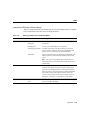
1
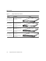
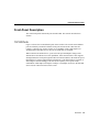
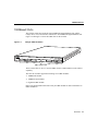
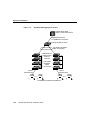
C H A PT E R
1
Overview
The Catalyst 3500 series XL switches are workgroup Ethernet switches that supply Gigabit
Ethernet and autosensing 10BaseT or 100BaseTX connections in individual switches and
in clustered configurations. These switches—also referred to as 3500 XL switches—can be
deployed as backbone switches aggregating 10/100 and Gigabit Ethernet traffic from other
switches and hubs or in mixed configurations connecting hubs, switches, servers, and
desktop computers or servers.
This chapter is a functional overview of the 3500 XL switches. The following topics briefly
describe the components and features that are shared by the switches in the series:
•
•
•
•
Switch features
Descriptions of the front and rear panels
Management options
Examples of the 3500 XL switches in different network topologies
Switch Features
The Catalyst 3500 XL switches are members of an extended network system of stackable,
modular LAN and WAN products that increase LAN performance, connect remote offices
and users, and provide secure access.
Figure 1-1 shows the four models of the switches, and Table 1-1 and Table 1-2 list their key
features. Switches running standard edition software are designated by the letter A, and
switches running Enterprise Edition Software are designated by the letters EN.
Overview 1-1
Switch Features
Figure 1-1
Catalyst 3500 Series XL Switches
Version
WS-C3508G-XL-A
Description
Switch
8 fixed GBIC1-based Gigabit
Ethernet ports
WS-C3508G-XL-EN
1
2
SYSTEM
3
RPS
MODE
4
5
6
STATUS
7
UTIL
8
DUPLX
SPEED
WS-C3512-XL-A
12 fixed autosensing10/100
Ethernet ports
WS-C3512-XL-EN
2 fixed GBIC-based Gigabit
Ethernet ports
1
WS-C3524-XL-A
24 fixed autosensing 10/100
Ethernet ports
WS-C3524-XL-EN
2 fixed GBIC-based Gigabit
Ethernet ports
5
6
7
8
9
10
11 12
1
2
2X
12X
2
3
4
5
6
7
8
9
10
11 12
13 14
1X
11X
13X
12X
14X
15 16
17 18
19 20
21 22
23 24
23X
SYSTEM
RPS
MODE
1
STATUS
UTIL
2
2X
DUPLX
SPEED
24X
48 fixed autosensing 10/100
Ethernet ports
2 fixed GBIC-based Gigabit
Ethernet ports
1. GBIC = Gigabit Interface Converter
1-2
4
11X
UTIL
Catalyst 3500 Series XL Installation Guide
1
1X
2
3
4
5
6
7
8
9
10
11 12
13 14
15 16
17 18
15X
17X
16X
18X
SYSTEM
19 20
21 22
23 24
25 26
27 28
29 30
31 32
33 34
31X
33X
32X
34X
RPS
35 36
37 38
39 40
41 42
43 44
45 46
47 48
47X
STATUS
1
UTIL
DUPLEX
SPEED
MODE
2X
48X
2
28011
WS-C3548-XL-EN
3
RPS
STATUS
DUPLX
SPEED
1
WS-C3548-XL-A
2
1X
SYSTEM
MODE
Switch Features
Table 1-1
Catalyst 3508G XL Features
Feature
Description
Performance and Configuration
• 8 GBIC-based 1000BaseX Gigabit Ethernet slots
• Support for up to 250 port-based virtual LANs (VLANs)
• Inter-Switch Link (ISL) and IEEE 802.1Q trunking support on all
ports (Enterprise Edition software only)
• IEEE 802.1p capable
• High-speed EtherChannel connections between switches and servers
• 8192 MAC addresses
• Cisco IOS Release 12.0(5)XP support
• Cisco Group Management Protocol (CGMP) to limit the flooding of
IP multicast traffic
• Broadcast storm control to prevent performance degradation from
broadcast storms
• Support for Cisco GBIC modules
— 1000BaseSX GBIC module
— 1000BaseLX/LH GBIC module
— GigaStack GBIC module
• Switched Port Analyzer (SPAN) port monitoring on any port
Management
• Cisco IOS command-line interface (CLI) through the console port or
Telnet
• CiscoView device-management application
• Cluster management, a web-based tool for managing switch clusters
through a single IP address
• Cisco Visual Switch Manager (CVSM) and Cisco Switch Network
View, web-based tools for managing individual switches and viewing
the network
• Simple Network Management Protocol (SNMP)
Redundancy
• Connection for optional Cisco 600W Redundant Power System
(RPS) that operates on AC input and supplies DC output to the switch
Overview 1-3
Switch Features
Table 1-2
Catalyst 3512, 3524, and 3548 XL Features
Feature
Description
Performance and Configuration
• Autonegotiation of speed and duplex operation on 10/100 Ethernet ports
• 12, 24, or 48 10/100 Ethernet ports and 2 GBIC-based Gigabit Ethernet slots
• Support for up to 250 port-based VLANs
• ISL and IEEE 802.1Q trunking support on all ports (Enterprise Edition
software only)
• High-speed EtherChannel connections between switches and servers
• 8192 MAC addresses
• Cisco IOS Release 12.0(5)XP support
• IEEE 802.1p capable
• CGMP to limit the flooding of IP multicast traffic
• Broadcast storm control to prevent performance degradation from broadcast
storms
• Support for Cisco GBIC modules
— 1000BaseSX GBIC module
— 1000BaseLX/LH GBIC module
— GigaStack GBIC module
• SPAN port monitoring on any port
Management
• Cisco IOS CLI through the console port or Telnet
• CiscoView device-management application
• Cluster management, a web-based tool for managing switch clusters through
a single IP address
• CVSM and Cisco Switch Network View, web-based tools for managing
individual switches and viewing the network
• SNMP
Redundancy
1-4
• Connection for optional Cisco 600W RPS that operates on AC input and
supplies DC output to the switch
Catalyst 3500 Series XL Installation Guide
Front-Panel Description
Front-Panel Description
The switch front panel contains the ports and the LEDs. This section describes these
features.
10/100 Ports
Figure 1-2 shows the 10/100 Ethernet ports on the switches. The switch 10/100 Ethernet
ports are internally switched to all other switch ports and use RJ-45 connectors and
Category 5 cabling. They operate at either 10 or 100 Mbps in full or half duplex. For
autonegotiation with other devices, the ports are IEEE 802.3u-compliant.
When connected to another device, a port senses the speed and duplex settings of the
attached device and advertises its own capabilities. If the connected device also supports
autonegotiation, the switch port negotiates the best connection (that is, the fastest line speed
that both devices support and full-duplex transmission, if the attached device supports it)
and configures itself accordingly. Ports can also be explicitly set to operate in any
combination of half duplex, full duplex, 10 Mbps, or 100 Mbps. In all cases, the attached
device must be within 100 meters of the switch.
Overview 1-5
Front-Panel Description
Catalyst 3512, 3524, and 3548 XL Switches
26235
Figure 1-2
1
2
3
4
5
6
7
8
9
10
11 12
1X
11X
SYSTEM
RPS
MODE
1
2X
STATUS
2
12X
UTIL
DUPLX
SPEED
10/100 ports
26237
GBIC module slots
1
2
3
4
5
6
7
8
9
10
11 12
13 14
1X
11X
15 16
17 18
19 20
21 22
23 24
13X
23X
SYSTEM
RPS
MODE
1
2X
STATUS
2
12X
UTIL
14X
DUPLX
24X
SPEED
10/100 ports
28010
GBIC module slots
1
1X
2
3
4
5
6
7
8
9
10
11 12
13 14
15 16
17 18
15X
17X
16X
18X
19 20
21 22
23 24
25 26
27 28
29 30
31 32
33 34
SYSTEM
RPS
31X
33X
32X
34X
35 36
37 38
39 40
41 42
43 44
45 46
47 48
47X
STATUS
UTIL
1
DUPLX
SPEED
MODE
2X
2
48X
10/100 ports
1-6
Catalyst 3500 Series XL Installation Guide
GBIC
module slots
1000BaseX Ports
1000BaseX Ports
The Catalyst 3508G XL switch has eight 1000BaseX Gigabit Ethernet slots, and the
Catalyst 3512, 3524, and 3548 XL switches have two1000BaseX Gigabit Ethernet slots.
Figure 1-2 and Figure 1-3 show the GBIC slots for the switches.
Catalyst 3508G XL Switch
18966
Figure 1-3
1
2
SYSTEM
3
RPS
MODE
4
5
6
STATUS
7
UTIL
8
DUPLX
SPEED
GBIC module slots
These switches have no factory installed GBIC modules. GBIC modules can be ordered
separately.
The 3500 XL switches support the following Cisco GBIC modules:
•
•
•
1000BaseSX module
1000BaseLX/LH module
GigaStack GBIC module
Refer to the documentation that came with your GBIC module for more information on
GBIC installation.
Overview 1-7
Front-Panel Description
Figure 1-4 shows a GBIC module installation.
Figure 1-4
Installing a GBIC Module in the Switch
Metal flap door
1
2
SYSTEM
RPS
GBIC module slot
1000BaseX GBIC module
1-8
Catalyst 3500 Series XL Installation Guide
3
18965
MODE
STATUS
UTIL
DUPLX
SPEED
1000BaseX Ports
The GigaStack GBIC supports one full-duplex link (in a point-to-point configuration) or up
to nine half-duplex links (in a stack configuration) to other Gigabit Ethernet devices. Using
the required Cisco proprietary signaling and cabling, it operates within distances of less
than 1 meter. The GigaStack GBICs can be installed in any of the GBIC slots on the
3500 XL switches. For additional instructions on installing and cabling a GigaStack GBIC,
refer to the Catalyst GigaStack Gigabit Interface Converter Installation Guide.
Figure 1-5 shows a GigaStack GBIC module installation.
Figure 1-5
Installing a GigaStack GBIC in the Switch
Metal flap door
1
2
SYSTEM
RPS
STATUS
UTIL
DUPLX
SPEED
3
22081
MODE
GBIC module slot
1
2
GigaStack
GBIC Module
Overview 1-9
Front-Panel Description
LEDs
You can use the switch LEDs described in this section to monitor switch activity and its
performance. Figure 1-6, Figure 1-7, and Figure 1-8 show the location of the LEDs and the
Mode button that you use to select one of the port modes. Changing a port mode changes
the information provided by each port status LED.
All of the LEDs described in this section except the utilization meter (UTL) are visible on
the CVSM home page and Cluster Manager page. The Cisco IOS Desktop Switching
Software Configuration Guide describes how to use CVSM to monitor individual switches
and how to use cluster management software to monitor all the switches in a cluster.
Figure 1-6
Catalyst 3508G XL LEDs
GBIC module slot LEDs
1
2
SYSTEM
RPS
System LED
Mode button
Redundant power system LED
Status LED
Utilization LED
Duplex LED
Speed LED
1-10
3
18961
MODE
STATUS
UTIL
DUPLX
SPEED
Catalyst 3500 Series XL Installation Guide
LEDs
Figure 1-7
Catalyst 3512 and 3524 XL LEDs
Port LEDs
1
2
3
4
5
6
7
8
9
10
1X
11 12
11X
SYSTEM
RPS
STATUS
UTIL
DUPLX
SPEED
2X
12X
22028
MODE
System LED
Mode button
Redundant power system LED
Status LED
Utilization LED
Duplex LED
Speed LED
The 10/100 ports on the Catalyst 3512, 3524, and 3548 XL switches are grouped in pairs.
For example, in Figure 1-7 and Figure 1-8, pair 1 and 2 is the left-most pair. The first
member of the pair (port 1) is above the second member (port 2). Port 3 is above port 4, and
so on.
Overview 1-11
Front-Panel Description
Figure 1-8
Catalyst 3548 XL LEDs
Port LEDs
1
2
3
4
5
6
1X
7
8
9
10
11 12
13 14
15 16
15X
SYSTEM
RPS
STATUS
UTIL
DUPLX
2X
16X
MODE
System LED
Mode label
28325
SPEED
Redundant power system LED
Status LED
Utilization LED
Duplex LED
Speed LED
System LED
The system LED shows whether the system is receiving power and is functioning properly.
Table 1-3 lists the LED colors and their meanings.
Table 1-3
1-12
System LED
Color
System Status
Off
System is not powered up.
Green
System is operating normally.
Amber
System is receiving power but is not functioning properly.
Catalyst 3500 Series XL Installation Guide
LEDs
RPS LED
The Redundant Power System (RPS) LED shows the RPS status. Table 1-4 lists the LED
colors and their meanings.
Table 1-4
RPS LED
Color
RPS Status
Off
RPS is off or is not installed.
Green
RPS is operational.
Blinking green
The RPS and the switch AC power supply are both powered up. If the
switch power supply fails, the switch powers down and after 15 seconds
restarts, using power from the RPS. The switch goes through its normal
boot sequence when it restarts.
Note This is not a recommended configuration.
Amber
RPS is connected but not functioning properly. One of the power supplies
in the RPS could be powered down, or a fan on the RPS could have failed.
Note If you are using an RPS with a revision level lower than Z3 with a
Catalyst 3508G or a Catalyst 3548 XL switch, the switch RPS LED might
display amber (normally indicating an RPS malfunction) even when the
RPS is functioning properly. The LEDs display correctly for RPS revision
level Z3 or later. The label on the bottom of the RPS shows the revision level.
Port Mode and Port Status LEDs
Catalyst 3500 XL switches have four LED modes, each providing different information
about a particular port or about the switch itself. The Mode button (shown in Figure 1-6 and
Figure 1-7) and the Mode label (shown in Figure 1-8) highlights each mode in sequence.
Overview 1-13
Front-Panel Description
LED modes provide the following information:
STATUS
The port status. This is the default mode.
UTL
The current bandwidth in use by the switch.
DUPLEX
The port duplex mode: full duplex or half duplex.
SPEED
The port operating speed: 10, 100, or 1000 Mbps.
See Table 1-5 for a description of the LED colors and their meanings for the different
modes.
Changing the Port Mode
To change the port mode, press the Mode button (see Figure 1-9) to highlight in sequence
each of the possibilities. Release the button to enable the highlighted function.
Note To change the port mode in the Catalyst 3548 XL switch, press the Mode label.
Figure 1-9
Changing the Port Mode
1
MODE
STATUS
UTIL
DUPLX
SPEED
Mode button
1-14
Catalyst 3500 Series XL Installation Guide
2
3
18962
SYSTEM
RPS
LEDs
Interpreting LEDs after a Mode Change
When you change port modes, the meaning of LED colors also changes. Table 1-5 explains
how to interpret the LED colors after you change the mode.
Table 1-5
Meaning of LED Colors in Different Modes
Port Mode
LED Color
Meaning
STATUS (port status)
Off
No link.
Solid green
Link present.
Flashing green
Activity; port is transmitting or receiving data.
Alternating green-amber
Link fault. Error frames can affect connectivity, and errors
such as excessive collisions, CRC errors, and alignment and
jabber errors are monitored for a link-fault indication.
Solid amber
Port is not forwarding. Port was disabled by management or an
address violation or was blocked by Spanning-Tree Protocol
(STP).
Note After a port is reconfigured, the port status LED can
remain amber for up to 30 seconds as STP checks the switch for
possible loops.
UTL (utilization)
Green
The LEDs display backplane utilization on a logarithmic scale.
If all port status LEDs are green, the switch is using 50% or
more of its total bandwidth capacity. If the right-most LED is
amber, the switch is using less than 50% of its total bandwidth.
If the LED to the left of the right-most LED is amber, the
switch is using less than 25% of its total capacity, and so on.
See Figure 1-10, Figure 1-11, and Figure 1-12 for details.
DUPLEX
Off
Port is operating in half-duplex.
Green
Port is operating in full-duplex.
Overview 1-15
Front-Panel Description
Table 1-5
Meaning of LED Colors in Different Modes (Continued)
Port Mode
LED Color
SPEED (speed)
10/100 ports
Meaning
Off
Port is operating at 10 Mbps.
Green
Port is operating at 100 Mbps.
1000BaseX ports
Off
Port is not operating.
Green
Port is operating at 1000 Mbps.
Figure 1-10, Figure 1-11, and Figure 1-12 show the bandwidth utilization percentages
displayed by the right-most LEDs.
Bandwidth Utilization for the Catalyst 3508G XL
Catalyst 3500
2
1
5
4
3
7
6
XL
22006
Figure 1-10
8
SYSTEM
RPS
MODE
STATUS
UTIL
DUPLX
SPEED
< 25%
25% – 49% +
50% +
1
1X
2
Bandwidth Utilization for the Catalyst 3524 XL
3
4
5
6
7
8
9
10
11 12
13 14
11X
15 16
17 18
19 20
13X
21 22
15X
1
RPS
MODE
STATUS
UTIL
2X
12X
14X
DUPLX
SPEED
< 25% +
25% – 49% +
50% +
1-16
Catalyst 3500 Series XL Installation Guide
XL
Catalyst 3500
23 24
SYSTEM
16X
2
22007
Figure 1-11
Rear-Panel Description
Figure 1-12
Bandwidth Utilization for the Catalyst 3548 XL
Catalyst 3500
1
2
3
24
5
1X
6
7
8
9
10
11 12
13 14
15 16
17 18
15X
19 20
21 22
23 24
25 26
27 28
29 31
31 32
17X
33 34
31X
33X
35 36
37 38
39 40
41 42
43 44
45 46
XL
47 48
47X
RPS
STATUS
UTIL
2
DUPLX
SPEED
2X
16X
32X
18X
MODE
34X
48X
28366
1
SYSTEM
< 25% +
25% – 49% +
50% +
If all port status LEDs on the Catalyst 3548 XL are green, the switch is using 50% or more
of its total bandwidth capacity. If all 10/100 port status LEDs are green and the lower GBIC
LED is amber, the switch is using between 25% and 50% of its total bandwidth. If all
10/100 port status LEDs are green and if both the GBIC LEDs are amber, the switch is
using less than 25% of its total capacity, and so on.
Rear-Panel Description
Switch rear panels have an AC power connector, an RPS connector, and an RJ-45 console
port (see Figure 1-13, Figure 1-14, and Figure 1-15). These components are described in
this section.
Power Connectors
You can provide power to the switch either by using the internal power supply or by
connecting the Cisco RPS to the switch RPS connector. The internal power supply is an
autoranging unit that supports input voltages between 100 and 240 VAC. If you plan to use
the internal power supply, use the supplied AC power cord to connect the AC power
connector to an AC power outlet.
Overview 1-17
Rear-Panel Description
Note Do not connect the switch power cord to an AC outlet if the switch is also connected
to a powered-up RPS. The switches do not support the fully-redundant configuration
described in the RPS Documentation. The redundant-with-reboot configuration is not
recommended.
Warning Attach only the Cisco RPS (model PWR600-AC-RPS) to the RPS
connector.
The Cisco RPS provides a quasi-redundant power source for four external devices that use
up to 150W DC each. Use a one-to-one cable (one connector at each cable end) to connect
four external devices to the four DC output power modules. The power source is
quasi-redundant because there are two AC input power modules for the Cisco RPS and one
DC output power module for each external device. The AC input to the Cisco RPS is fully
redundant, but the DC output to the external devices is not.
For more information on the Cisco RPS, refer to the Cisco RPS documentation.
Console Port
You can connect a 3500 XL switch to a PC or terminal by means of the console port and
the supplied rollover cable. For the data characteristics of the console port, see the
“Connecting a Terminal or PC to the Console Port” section on page 2-20.
1-18
Catalyst 3500 Series XL Installation Guide
Console Port
Catalyst 3508G XL Rear Panel
18963
Figure 1-13
RATING
100-127/200-240V~
1.0A/0.5A 50-60HZ
DC INPUTS FOR REMOTE POWER
SUPPLY
SPECIFIED IN MANUAL. +3.3V***@14
A,
+12V***@3A
DC INPUT
CONSOLE
Fans
AC power
connector
RJ-45
console port
Redundant
power system
connector
Catalyst 3512 XL and 3524 XL Rear Panel
18964
Figure 1-14
RATING
100-127/200-240V~
1.0A/0.5A 50-60HZ
AC power
connector
CONSOLE
DC INPUTS FOR REMOTE
POWER SUPPLY
SPECIFIED IN MANUAL.
+5V @24A, +12V @.5A
Fans
RJ-45
console port
Redundant
power system
connector
Overview 1-19
Management Options
Catalyst 3548 XL Rear Panel
28012
Figure 1-15
DC INPUTS FOR REMOTE
POWER SUPPLY
SPECIFIED IN MANUAL
+3.3V @17A, +12 @1.1A
RATING
100-127/200-240V~
1.6A/0.9A 50-60HZ
AC power
connector
Fan
exhaust
CONSOLE
RJ-45
console port
Redundant
power system
connector
Management Options
Catalyst 3500 XL switches offer several management options:
•
Cisco Visual Switch Manager (CVSM) application
Using CVSM, you can use a Web browser to manage a switch, to display network maps,
and to monitor the network. See the Cisco IOS Desktop Switching Software
Configuration Guide and the online help in the CVSM application for more information.
•
Cluster Management application
Switches using Cisco IOS Release 12.0(5)XP software are command-capable and can
also be cluster member switches. If your switch is a cluster member or a command
switch, you can use cluster management software. See the Cisco IOS Desktop Switching
Software Configuration Guide and the online help in the cluster management
application for more information.
•
Cisco IOS command-line interface (CLI)
You can access the CLI by connecting a PC or terminal directly to the console port on
the rear panel of the switch. If the switch is connected to your network, you can use a
Telnet connection to manage the switch from a remote location. See the Cisco IOS
1-20
Catalyst 3500 Series XL Installation Guide
Deployment Strategies
Desktop Switching Command Reference for more information.
•
CiscoView application
The CiscoView device-management application displays the switch image that you can
use to set configuration parameters and to view switch status and performance
information. The CiscoView application, which you purchase separately, can be a
standalone application or part of an SNMP network-management platform. See the
CiscoView documentation for more information.
•
Simple Network Management Protocol (SNMP) network management
You can manage switches by using an SNMP-compatible management station running
platforms such as HP OpenView or SunNet Manager. The switch supports a
comprehensive set of MIB extensions and MIB II, the IEEE 802.1D bridge MIB, and
four Remote Monitoring (RMON) groups. See the documentation that came with your
SNMP application for more information.
Deployment Strategies
This section provides examples of how you could deploy the 3500 XL switches in your
network.
•
•
GigaStack GBIC aggregation solution
Wiring closet aggregator solution
GigaStack GBIC Aggregation Solution
Figure 1-16 shows a Catalyst 3508G XL switch with GigaStack GBIC connections
aggregating full-duplex traffic from two Catalyst 2900 XL or 3500 XL switch stacks to an
enterprise switch (such as the Catalyst 8500). The two Catalyst 2900 XL or 3500 XL
switches are daisy-chained together using GigaStack GBICs in half-duplex mode, creating
an 1-Gbps independent stacking backplane. In this deployment, the uplink from the
Catalyst 3508G XL is either a Gigabit EtherChannel or a 1000BaseX connection.
Overview 1-21
Deployment Strategies
Figure 1-16
GigaStack GBIC Aggregation Solution
Catalyst 8500, 6000,
5500, or 4000 series switch
Gigabit EtherChannel
or 1000BaseX connections
Catalyst 3508G XL switch
Full-duplex GigaStack
GBIC connections
Catalyst 2900 or
Catalyst 3500
series XL
switches
Half-duplex
GigaStack
GBIC
connections
10/100
switched links
18230
10/100
switched links
10/100BaseTX attached workstations
1-22
Catalyst 3500 Series XL Installation Guide
Wiring Closet Aggregator
Wiring Closet Aggregator
Figure 1-17 shows a Catalyst 3508G XL aggregating traffic from two 2900 XL or 3500 XL
switches to an enterprise switch (such as a Catalyst 8500). In this deployment, the
full-duplex connection is either a GigaStack GBIC or a 1000BaseX connection, and the
uplink is either a 1000BaseX or a Gigabit EtherChannel connection.
Figure 1-17
Catalyst 3508G Switch in a Wiring Closet
Catalyst 8500, 6000,
5500, or 4000 series switch
Catalyst 3508G XL
switch
1000BaseX or
Gigabit EtherChannel
connections
Full-duplex GigaStack GBIC or
1000BaseX connections
10/100
switched links
18231
10/100
switched links
Catalyst 2900
or Catalyst 3500
series XL switches
10/100BaseTX attached workstations
Overview 1-23
Deployment Strategies
1-24
Catalyst 3500 Series XL Installation Guide