1
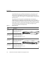
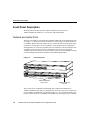
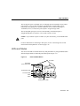
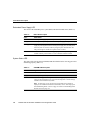
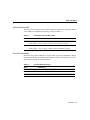
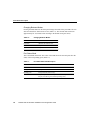
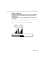
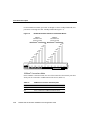
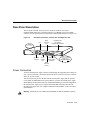
C H A PT E R
1
Overview
This chapter introduces the FastHub 400 series and covers the following topics:
•
•
•
•
Summary of key features
Descriptions of the front and rear panels
Overview of the management options supported by the FastHub 400M models
Examples of network configurations using the hub
Key Features
The FastHub 400 series (shown in Figure 1-1 and described in Table 1-1) is a family of
stackable, 12- or 24-port, autosensing 10/100-Mbps Class II repeaters:
•
The FastHub 412M and FastHub 424M models (hereafter referred to as the
FastHub 400M models) are management hubs that can be configured and monitored
through web-based and command-line interfaces and Simple Network Management
Protocol (SNMP). You can also use these hubs to manage a stack of up to three other
FastHub 400 models and serve up to 96 user connections.
•
The FastHub 412 and FastHub 424 models are manageable hubs that can be configured
and monitored through interconnection to a FastHub 412M or FastHub 424M model.
Overview 1-1
Key Features
Each FastHub model can be a standalone networking device or can connect to servers,
switches, routers, and other hubs to form a larger network. You can also stack and
interconnect up to four FastHub 400 models to form a larger network. See the “Network
Configuration Examples” section on page 1-18 for additional examples of using the hub in
different networks.
The expansion slot on the rear panel of each FastHub model is for the optional
10BaseT/100BaseTX or 100BaseFX switched uplink module. These switched uplink
modules can provide extended distances to other network devices such as servers, hubs, and
routers. The maximum cable length for connecting to the 10BaseT/100BaseTX switched
uplink module is 100 meters. The maximum cable length for connecting to the 100BaseFX
switched uplink module with multimode fiber-optic cable in half-duplex mode is
412 meters and 2 kilometers in full-duplex mode.
Figure 1-1
FastHub 400 Series
Model
Description
FastHub 412 hub
(WS-C412)
12 autosensing 10/100 network ports
1 autosensing 10/100 uplink port
1 high-speed expansion slot
(on rear panel)
RPS
10BaseT/100BaseTx
1x
2x
3x
4x
5x
6x
7x
8x
9x
10x
11x
8x
9x
10x
11x
12x
12
MODE
FastHub 412M hub
(WS-C412M)
12 autosensing 10/100 network ports
1 autosensing 10/100 uplink port
1 high-speed expansion slot (on rear panel)
1 console port (on rear panel)
FastHub 424 hub
(WS-C424)
24 autosensing 10/100 network ports
1 autosensing 10/100 uplink port
1 high-speed expansion slot
(on rear panel)
RPS
10BaseT/100BaseTx
1x
2x
3x
4x
5x
6x
7x
12x
13x
14x
15x
16x
17x
18x
19x
20x
21x
22x
23x
24x
24
FastHub 424M hub
(WS-C424M)
1-2
24 autosensing 10/100 network ports
1 autosensing 10/100 uplink port
1 high-speed expansion slot (on rear panel)
1 console port (on rear panel)
FastHub 400 10/100 Series Installation and Configuration Guide
15227
MODE
Key Features
Table 1-1
Feature Summary
Feature
Description
Performance
• Autosensing on all ports allows automatic configuration for either 10BaseT or 100BaseT
connections.
• 10- and 100-Mbps peak and aggregate throughput.
• Autonegotiation of speed and duplex operation on the optional 10BaseT/100BaseTX
module port.
• Autonegotiation of duplex operation on the optional 100BaseFX module port.
Manageability
• Single management hub required for each four-unit hub stack.
(FastHub 400M
models)
• Embedded web interface for most management tasks.
• Command-line interface providing all management options through Telnet in-band or
console port out-of-band connections.
• Menu-based diagnostic console for hub recovery tasks.
• Simple Network Management Protocol (SNMP) and Remote Monitoring (RMON)
supporting full configuration, management, and monitoring on a per-port, per-hub, and
per-hub-stack basis.
• Cisco Discovery Protocol (CDP) providing integration with CiscoView network
management software.
• Power-on self test (POST).
Flexibility
• Integrated stacking connectors allow up to four hubs in a single collision domain:
— Up to 96 ports in a four-unit hub stack configuration, functioning as one logical
repeater.
— Up to 190 ports in a two-hub stack configuration, creating a single collision domain.
• No disruption to network activity when adding or removing hubs from the hub stack.
• Optional 10BaseT/100BaseTX or 100BaseFX switched uplink module.
Redundancy
• Managed hubs can be deployed redundantly in a hub stack for management backup.
• Connection for optional Cisco 600W AC Redundant Power System (RPS) as a backup
power source.
Overview 1-3
Front-Panel Description
Front-Panel Description
The front panel of the hubs provides 10BaseT/100BaseTX network ports, a
10BaseT/100BaseTX uplink port, a set of LEDs, and a Mode button.
Network and Uplink Ports
The front of each hub provides autosensing 10BaseT/100BaseTX network and uplink ports
(see Figure 1-2). These ports, hereafter referred to as 10/100 ports, can operate at either 10
or 100 Mbps. When connected to another device, each 10/100 port senses the speed setting
of that device and advertises its own capabilities. If the connected device also supports
autonegotiation, the 10/100 port negotiates the best connection it can and configures itself
accordingly. If the other device does not autonegotiate, the 10/100 port operates at
10 Mbps. You can also explicitly set the 10/100 ports to operate at 10 or 100 Mbps by using
one of the management interfaces available to the FastHub 400M models.
Figure 1-2
Front-Panel Ports
10BaseT/100BaseTx
RPS
1x
2x
3x
4x
5x
6x
7x
8x
9x
8x
9x
10x
11x
12x
12
MODE
1x
2x
3x
4x
5x
6x
7x
10x
11x
12x
13x
14x
15x
16x
17x
18x
19x
20x
21x
22x
23x
24x
24
10BaseT/100BaseTX
network ports
15312
10BaseT/100BaseTx
RPS
MODE
10BaseT/100BaseTX
uplink port
The 10/100 ports are compatible with the IEEE 802.3 10BaseT and IEEE 802.3u
100BaseT standards. These ports use standard RJ-45 connectors, and you can connect these
ports to 10BaseT-compatible devices through Category 3, 4, or 5 twisted-pair cabling. You
can also connect these ports to 100BaseTX-compatible devices through Category 5 cabling.
1-4
FastHub 400 10/100 Series Installation and Configuration Guide
LEDs and Modes
The 10/100 ports (ports 1x through 12x or 1x through 24x) are internally crossed. These
ports require a crossover cable to connect to another hub or switch (unless you are
connecting to the uplink port on another FastHub or device). When connecting to a
workstation, server, or router, these ports require a straight-through cable.
The 10/100 uplink port (port 12 or 24) is not internally crossed and requires a
straight-through cable to connect to a server, hub, switch, or router.
Caution If you connect to ports 12x and 12 (or ports 24x and 24), you will disable both
ports.
For more information on connecting to these ports, see the “Connecting to the 10/100
Network Ports and Uplink Port” section on page 2-18.
LEDs and Modes
You can use the LEDs to monitor hub activity and performance by using the Mode button
and selecting the modes in which the port LEDs operate (Figure 1-3).
Figure 1-3
LEDs and Mode Button
Port LEDs
Redundant
power system LED
System status LED
1x
2x
3x
4x
Port mode LEDs
14507
Mode
button
Activity/collision LEDs
Overview 1-5
Front-Panel Description
Redundant Power Supply LED
The colors of the redundant power system (RPS) LED show the RPS status (Table 1-2).
Table 1-2
RPS LED Description
Color
RPS Status
Off
Internal power supply is powered up. RPS is not powered up.
Solid green
RPS is powered up and operational. Internal power supply is not powered up.
Flashing green
Internal power supply and RPS are both powered up and the internal power
supply is powering the hub. If the internal power supply fails, the hub powers
down and, after 15 seconds, restarts by using the power from the RPS. The
hub goes through its normal boot sequence when it restarts.
Solid amber
RPS is connected but not functioning properly. One of the power supplies in
the RPS could be powered down or a fan on the RPS could have failed.
System Status LED
The colors of the system status (SYSTEM) LED show that the hub is receiving power and
functioning properly (Table 1-3).
Table 1-3
SYSTEM LED Description
Color
System Status
Off
Hub is not powered up.
Solid green
Hub is operating normally.
Solid amber
Hub is receiving power but might not be functioning properly. One or more
power-on self-test (POST) errors occurred. The Diagnostic Console message
identifies which nonfatal test(s) failed.
Note If a fatal error occurs, the hub is not operational and no message is
displayed. For additional information about POST, see the “Powering Up the
Hub and Running POST” section on page 2-6 and the “Understanding POST
Results” section on page 4-4.
1-6
FastHub 400 10/100 Series Installation and Configuration Guide
LEDs and Modes
Activity/Collision LEDs
The colors of the 10 and 100 activity/collision LEDs show the activity and packet collision
on the 10BaseT and 100BaseTX segments, as shown in Table 1-4.
Table 1-4
Activity/Collision LED Description
LED
Activity and Collision Status
10
Flashing green—There is network traffic on the hub 10BaseT segment.
Flashing amber—There are packet collisions on the hub 10BaseT segment.
100
Flashing green—There is network traffic on the hub 100BaseTX segment.
Flashing amber—There are packet collisions on the hub 100BaseTX segment.
Port LEDs and Modes
Each network port has an LED above it. These LEDs, as a group or individually, display
information about the hub and about individual ports. Table 1-5 describes how to use the
Mode button to change the LED information.
Table 1-5
Port LED Modes Summary
Mode
Determines...
Port status (default)
Status of individual network ports
Bandwidth utilization
Percentage of the hub total bandwidth being used at any one time
100BaseT connections
Which ports are connected to 100BaseTX network devices
Overview 1-7
Front-Panel Description
Changing Between Modes
Pressing the Mode button on the front panel changes the mode of the port LEDs. The 100
and UTL LEDs show which mode is active (Table 1-6). The selected mode remains on
approximately for 30 seconds before returning to the default mode (port status).
Table 1-6
Changing Between Modes
For this Mode...
Push the Mode Button Until...
Port status
100 and UTL LEDs are off.
Bandwidth utilization
Only the UTL LED is on.
100BaseT connections
Only the 100 LED is on.
Port Status Mode
This is the default LED mode. The colors of the LEDs above the network ports show the
status of the corresponding ports (Table 1-7).
Table 1-7
1-8
Port Status Mode LED Description
Color
Port Status
Off
No link.
Solid green
Link operational.
Flashing green
Link operational (with activity).
Amber
The port is partitioned. After a packet is successfully sent over
this port, the LED is green (normal operating state).
FastHub 400 10/100 Series Installation and Configuration Guide
LEDs and Modes
Bandwidth Utilization Mode
In the UTL mode, the port LEDs as a group show what percentage of the hub bandwidth is
being used at any one time. The more LEDs that are lit, the higher the percentage of
bandwidth being used.
The hub uses different sets of LEDs to the indicate bandwidth being used at either speed
(10 or 100 Mbps).
For the FastHub 412 models, port LEDs 1x through 6x show 10-Mbps bandwidth, and port
LEDs 7x through 12x show 100-Mbps bandwidth (Figure 1-4).
Figure 1-4
Bandwidth Utilization Mode for FastHub 412 Models
100BaseT
bandwidth used
(Percent of total)
10BaseT
bandwidth used
(Percent of total)
100
100
83.5
66.8
83.5
66.8
50.1
50.1
33.4
33.4
16.7
16.7
2x
3x
4x
5x
6x
7x
8x
9x
10x
11x
12x
12
H11687
10BaseT/100BaseTx
1x
Overview 1-9
Front-Panel Description
For the FastHub 424 models, port LEDs 1x through 12x show 10-Mbps bandwidth, and
port LEDs 13x through 24x show 100-Mbps bandwidth (Figure 1-5).
Figure 1-5
Bandwidth Utilization Mode for FastHub 424 Models
100BaseT
bandwidth used
(Percent of total)
10BaseT
bandwidth used
(Percent of total)
100
91.3
83.0
100
91.3
83.0
74.7
66.4
58.1
49.8
41.5
33.2
24.9
16.6
8.3
74.7
66.4
58.1
49.8
41.5
33.2
24.9
16.6
8.3
2x
3x
4x
5x
6x
7x
8x
9x
10x
11x
12x
13x
14x
15x
16x
17x
18x
19x
20x
21x
22x
23x
24x
24
H11688
10BaseT/100BaseTx
1x
100BaseT Connections Mode
In the 100BaseT connections mode, the color of the LEDs above the network ports show
which ports are connected to 100BaseTX network devices (Table 1-8).
Table 1-8
1-10
100BaseT Connections LED Description
LED Status
100BaseT Connections Status
Solid green
Port is connected to a 100BaseTX network device.
Off
Port is connected to a 10BaseTX network device.
FastHub 400 10/100 Series Installation and Configuration Guide
Rear-Panel Description
Rear-Panel Description
The rear panel of the hub has an AC power connector, an RJ-45 console port
(FastHub 400M models only), stacking connectors, a redundant power system (RPS)
connector, and an expansion slot for an optional switched uplink module (see Figure 1-6).
Rear-Panel Connectors, Console Port, and Expansion Slot
Stack
connector
(up)
Fan
RATING
100-127 / 200-240 V~
2A /1A 50 / 60 Hz
RATING
100-127 / 200-240 V~
2A /1A 50 / 60 Hz
UP
CONSOLE
Expansion slot
for optional
switched uplink module
14517
Figure 1-6
DC INPUTS FOR REMOTE
POWER SUPPLY
SPECIFIED IN MANUAL
+5V @6A, +12V @1A
DC INPUT
DOWN
MEDIA MODULE
AC power
connector
RJ-45
console
port
Redundant
power system
connector
Stack
connector
(down)
DC INPUTS FOR REMOTE
POWER SUPPLY
SPECIFIED IN MANUAL
+5V @6A, +12V @1A
Power Connectors
To use the internal power supply, which is an autoranging unit supporting input voltages of
90 to 127/200 to 250 VAC, connect the supplied AC power cord to the AC power connector
and to an AC power outlet.
You can also provide power to the hub with the internal power supply and the optional
Cisco 600W AC Redundant Power System (RPS). If you have the internal power supply
and the RPS powered up at the same time, the RPS LED flashes green. In this configuration,
the internal power supply is powering the hub, and the RPS will power the hub if the
internal power supply fails. For complete information about the RPS, see the Cisco RPS
documentation.
Warning Attach only the Cisco RPS (model PWR600-AC-RPS) to the RPS receptacle.
Overview 1-11
Rear-Panel Description
Stacking Connectors
You can interconnect hubs by using the stacking connectors on the rear panel of the hubs.
The interconnected hubs in the hub stack appear to the rest of the network and to the
management interface as a single logical repeater.
You can purchase a stacking cable (model number WS-C400-CAB-EXP) to interconnect
the hub to another FastHub 400 model. You can interconnect up to four hubs in a hub stack.
To manage the hub stack, at least one of the hubs must be a FastHub 412M or
FastHub 424M model. See Appendix C, “FastHub Stacks,” for more details.
Expansion Slot
The expansion slot is for the optional 10BaseT/100BaseTX or the 100BaseFX switched
uplink module. You can connect the module port to backbone switches, routers, servers,
and hubs with Category 5 or fiber-optic cabling. For more information about these modules,
see Appendix D, “Switched Uplink Modules.”
Console Port (FastHub 400M Models)
You can configure and manage the hub through the FastHub 400 series Hub Manager
web-based interface, command-line interface (CLI), or Simple Network Management
Protocol (SNMP). To do so, you must connect the console port to a management station or
modem with the supplied RJ-45-to-RJ-45 rollover console cable and an appropriate
adapter. For additional information, see the “Connecting to the Console Port (FastHub
400M Models)” section on page 2-14.
1-12
FastHub 400 10/100 Series Installation and Configuration Guide
Management Options (FastHub 400M Models)
Management Options (FastHub 400M Models)
The FastHub 400M models provide the capability to manage a single hub or a hub stack.
You can use the default settings shipped with the hub, or you can customize the
configuration of the hub through the FastHub 400 series Hub Manager web-based interface,
the CLI, or SNMP.
The FastHub 400 series Hub Manager is the easiest interface to use for the basic
configuration and monitoring tasks. To perform all the configuration and monitoring tasks,
use the CLI and SNMP.
This section provides the following information:
•
•
List of default configuration settings for the hub
Overview of the FastHub 400 series Hub Manager and the basic management tasks you
can perform using it
Note Procedures for performing management tasks and detailed information about the
FastHub 400 series Hub Manager pages are also provided in the FastHub 400 series Hub
Manager online help.
•
Overview of the CLI, which is fully described in the FastHub 400 10/100 Series
Command Reference.
•
Overview of SNMP and the hub Management Information Base (MIB) files.
Note The menu-based diagnostic console is described in the “Recovery Procedures Using
the Diagnostic Console” section on page 4-6.
Overview 1-13
Management Options (FastHub 400M Models)
Default Configuration Settings
The hub is designed to operate with little or no user intervention. After you assign the IP
information, the hub uses its default settings (Table 1-9) and begins forwarding packets as
soon as it is powered up and connected to compatible devices.
Table 1-9
Default Settings and FastHub 400 series Hub Manager Pages
Feature
Default Setting
Hub Manager Page
IP information
0.0.0.0
IP Management Page
Stack management
—
Group Management Page
Cisco Discovery Protocol (CDP)
Enabled
CDP Management Page
Autonegotiate
Port Management Page
Management
Performance Tuning
Speed of ports
Switched Uplink Module
Management Page
Duplex mode of module ports
Autonegotiate
Switched Uplink Module
Management Page
Hub password
None
Home Page
Community string
public/private
SNMP Management Page
Security
Trap manager
None
SNMP Management Page
Write manager
None
SNMP Management Page
—
Detailed Port Statistics Page
Diagnostics
Usage reports
Detailed Switched Uplink
Module Statistics Page
Detailed Group Statistics Page
Remote monitoring
Enabled
—
—
System Configuration Page
Upgrades
Firmware
For procedures on how to reset all hub console port settings to the factory defaults, see the
“Resetting the Hub to the Factory Defaults” section on page 4-15.
1-14
FastHub 400 10/100 Series Installation and Configuration Guide
Overview of the FastHub 400 Series Hub Manager
Overview of the FastHub 400 Series Hub Manager
The FastHub 400 series Hub Manager (hereafter referred to as the hub manager) is a
web-based graphical user interface for basic hub configuration and monitoring. Using the
hub manager, you can configure and monitor the hub from anywhere on your intranet.
Each hub manager page
•
•
•
Provides fields, check boxes, and lists for changing the configuration settings
Displays current information about the hub
Provides online help for each page
— Detailed information about the fields, lists, check boxes, and buttons
— Specific procedures for performing management tasks
To use the hub manager, you must have one of these web browsers installed on your
management station:
•
•
Netscape Communicator 4.03 or higher
Microsoft Internet Explorer 4.01 or higher
Management Tasks Supported on the Hub Manager
The management tasks you can perform from the hub manager can be grouped as described
in Table 1-10.
Procedures for accessing and using the hub manager are provided in
•
•
“Accessing the FastHub 400 Series Hub Manager” section on page 2-21
Chapter 3, “Configuring and Monitoring from the Hub Manager”
Note Information provided in Chapter 3, “Configuring and Monitoring from the Hub
Manager,” is also provided in the hub manager online help.
Overview 1-15
Management Options (FastHub 400M Models)
Table 1-10
Configuration and Monitoring Tasks
Changing Hub and Port Configuration Settings
Assigning or Changing Basic Hub Information on page 3-4
Changing the Port Settings on page 3-14
Changing the Module Port Settings on page 3-20
Managing the Hub Segments on page 3-27
Changing the Hub IP Information on page 3-32
Changing the CDP Settings on page 3-37
Changing the System Configuration on page 3-40
Changing Hub Security
Assigning or Changing the Hub Password on page 3-6
Changing the SNMP Settings on page 3-34
Monitoring Hub and Port Conditions
Using the Hub Image to Monitor the Hub on page 3-7
Checking or Resetting Port Statistics on page 3-18
Checking or Resetting Module Statistics on page 3-24
Checking or Resetting Hub Statistics on page 3-30
Remote Monitoring on page 2-25
Overview of the Command-Line Interface
Using the CLI, you can access the hub software and perform the same basic system
configuration and system monitoring tasks available through the hub manager. You can also
perform privileged configuration and troubleshooting tasks available only through the CLI
and SNMP.
Procedures describing how to access the CLI are in the “Accessing the CLI” section on
page 2-23. For complete information about using the CLI, refer to the FastHub 400 10/100
Series Command Reference.
1-16
FastHub 400 10/100 Series Installation and Configuration Guide
Overview of SNMP
Overview of SNMP
You can configure and monitor the hub by accessing the Management Information Base
(MIB) variables through Simple Network Management Protocol (SNMP), an
application-layer protocol facilitating the exchange of management information between
network devices. The hub supports a comprehensive set of MIB objects, including four
Remote Monitoring (RMON) groups. (The “Accessing the MIB Files through SNMP”
section on page 2-23 provides information about the MIB files and about accessing them.)
The SNMP system consists of three parts: SNMP manager, SNMP agent, and the MIB files.
SNMP places all operations in a get-request, get-next-request, and set-request format. For
example, an SNMP manager can get a value from an SNMP agent or store a value into that
SNMP agent. The SNMP manager can be part of a network management system (NMS),
and the SNMP agent can reside on a networking device such as a hub. You can compile the
hub MIB files with your network management software. The SNMP agent can respond to
MIB-related queries being sent by the NMS.
An example of an NMS is the CiscoWorks network management software. CiscoWorks
uses the hub MIB variables to set device variables and to poll devices on the network for
specific information. The results of a poll can be displayed as a graph and analyzed in order
to troubleshoot internetworking problems, increase network performance, verify the
configuration of devices, monitor traffic loads, and more.
Figure 1-7 shows how the SNMP agent gathers data from the MIB file, which holds
information about device parameters and network data. The agent can send traps, or
notification of certain events, to the manager.
NMS
SNMP Network
Get-request, Get-next-request,
Get-bulk, Set-request
Get-response, traps
SNMP Manager
Network device
MIB
SNMP Agent
S1203a
Figure 1-7
Note Make sure you use the correct Read and Write community strings so that your
SNMP request does not fail. Refer to the SNMP Management Page for the correct
community strings.
Overview 1-17
Network Configuration Examples
The SNMP manager uses information in the MIB files to perform the operations described
in Table 1-11.
Table 1-11
SNMP Manager Operations
Operation
Description
get-request
Retrieves a value from a specific variable.
get-next-request
Retrieves a value from a variable within a table.1
get-response
Reply to a get-request, get-next-request, and set-request sent by an NMS.
set-request
Store a value in a specific variable.
trap
Send an unsolicited message from an SNMP agent to an SNMP manager
indicating that some event has occurred.
1
An SNMP manager does not need the exact variable name. It sequentially searches to find the needed variable
from within a table.
Network Configuration Examples
This section provides the following example configurations of networks using the
FastHub 400 series:
•
•
•
1-18
Client/server workgroups
Server farms
Extended network
FastHub 400 10/100 Series Installation and Configuration Guide
Client/Server Workgroups
Client/Server Workgroups
You can create 10- and 100-Mbps workgroups by cascading and interconnecting
FastHub 400 models. In Figure 1-8, three FastHub 400 models connect to a switch or router
through the optional FastHub 400 switched uplink module ports. In full-duplex mode,
200-Mbps bandwidth to the switch or router is available to all three FastHub 400 switched
uplink module ports. The distance to the switch or router can be increased to 2 kilometers
by using the 100BaseFX module port in full-duplex mode with multimode fiber-optic
cabling (412 meters in half-duplex mode). When connected to a 10/100 switched uplink
module on the hub, the switch or router must be within 100 meters of the hub.
Figure 1-8
Client/Server Workgroups
100BaseT-enabled
router or switch
10 or 100 Mbps shared
or switched links
100 Mbps
(200 Mbps full duplex)
switched links
FastHub
412
stack
FastHub 424 hub
10 or 100 Mbps
shared links
10 or 100 Mbps
switched link
Workgroup of up to
48 users and servers
Workgroup of up to 23 users and servers
FastHub 412 hub
10 or 100 Mbps shared
or switched links
Workgroup of up to 96 users and servers
10 or 100 Mbps
shared links
14508
FastHub
424
stack
10 or 100 Mbps
shared link
Workgroup of up to 11 users and servers
Overview 1-19
Network Configuration Examples
Server Farms
You can use the FastHub 400 models to create 10- and 100-Mbps server farms to increase
centralized and decentralized server performance as shown in Figure 1-9.
Figure 1-9
Server Farms
FastHub 424 stack
100 Mbps
(200 Mbps full duplex)
switched links
Catalyst 2900 XL series
or Catalyst 1900/2820
series
100 Mbps
(200 Mbps
full duplex)
switched links
FastHub 424 hub
10 or 100 Mbps
shared or
switched links
FastHub 412 hub
10 or 100 Mbps
shared links
10 or 100 Mbps
shared links
Server farm of up to
12 servers
Server farm of up to
24 servers
1-20
14509
Catalyst 5000 series
or Cisco 7000 series
FastHub 400 10/100 Series Installation and Configuration Guide
Centralized server farm
of up to 96 servers
Extended Network
Extended Network
A system of routers, switches, and hubs can be combined to create a high-performance
network that extends beyond the main office LAN to connect to branch offices, remote sites,
mobile users, and the Internet. Figure 1-10 is an example of an extended network.
Figure 1-10
Extended Network
Internet
Branch office
Cisco 1600 or
2500 series
Catalyst 1900
series
Main office
100BaseT
server
Catalyst 2900 XL series,
Catalyst 2820 series, or
Cisco 3600
Catalyst 1900 series
series
Single workstations
FastHub
400 series
Single workstations
Cisco 700 series
CiscoRemote
14510
10BaseT/100BaseTX
workstations and servers
Remote sites and mobile users
Overview 1-21
Network Configuration Examples
1-22
FastHub 400 10/100 Series Installation and Configuration Guide