1
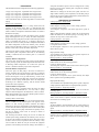
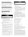
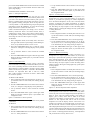
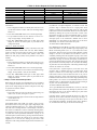
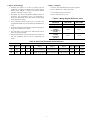
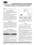
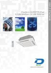
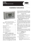
Programmable Dual Fuel Thermostats
Visit www.carrier.com
Installation, Start-Up, and Operating Instructions
NOTE: Read the entire instruction manual before starting the
installation.
This symbol → indicates a change since the last issue.
INDEX
Page
SAFETY CONSIDERATIONS .....................................................1
INTRODUCTION ..........................................................................1
SYSTEM CONSIDERATIONS ....................................................1
APPLICATION ..............................................................................2
DESCRIPTION OF OPERATION ............................................2-3
INSTALLATION CONSIDERATIONS .......................................3
INSTALLATION......................................................................3-12
Thermostat Location .................................................................3
Set DIP Switches...................................................................3-4
Install Thermostat .....................................................................4
Set Thermostat Configuration ...............................................4-6
Check Thermostat Operation....................................................6
Final Settings ............................................................................7
Checklist....................................................................................7
WIRING DIAGRAMS .............................................................7-10
OPERATIONAL INFORMATION.............................................11
TROUBLESHOOTING ...............................................................11
CONFIGURATION RECORD....................................................12
→ SYSTEM CONSIDERATIONS
The dual fuel thermostat is designed to be used only in HP/furnace
installations. It replaces a conventional 2-stage HP thermostat and
a HP/furnace interface kit. An outdoor temperature sensor, Part
No. TSTATXXSEN01-B MUST be used with this thermostat. It is
supplied with thermostat.
As an ENERGY STAR Partner, Carrier Corporation has
determined that this product meets the ENERGY STAR
guidelines for energy efficiency.
SAFETY CONSIDERATIONS
Read and follow manufacturer instructions carefully. Follow all
local electrical codes during installation. All wiring must conform
to local and national electrical codes. Improper wiring or installation may damage thermostat.
Recognize safety information. This is the safety-alert symbol
.
When you see this symbol on the equipment and in the instruction
manual, be alert to the potential for personal injury.
Understand the signal words DANGER, WARNING, and CAUTION. These words are used with the safety-alert symbol. DANGER identifies the most serious hazards which will result in severe
personal injury or death. WARNING signifies a hazard which
could result in personal injury or death. CAUTION is used to
identify unsafe practices which would result in minor personal
injury or product and property damage.
INTRODUCTION
Carrier’s 7-day programmable dual fuel thermostat is a wallmounted, low-voltage thermostat which provides proper control of
a heat pump (HP) and furnace combination without using a
HP/furnace interface kit. Separate heating and cooling set points,
plus auto changeover allow setback programming for maximum
energy savings. Up to 4 time/temperature settings per 24 hour
period for 7 independent days may be programmed. Batteries are
not required; during a power interruption, the internal memory
stores programs for an unlimited time and the clock continues to
run for at least 72 hrs.
A98426
HEIGHT (IN.)
4-1/4
WIDTH (IN.)
7-1/2
DEPTH (IN.)
1-3/8
→ Fig. 1—Carrier Programmable Thermostat
If HP is not already equipped with a high-pressure switch, one
must be added for dual fuel applications. It protects HP from
overpressure which would occur if a failure resulted in both
HP and furnace operating at same time. Kit No.
KSAHI0201HPS includes required switch and instructions
for its proper installation.
A HP/furnace installation has several special requirements. Foremost is that furnace and HP must not be allowed to operate at same
time, except during HP defrost. A second is to have furnace
complete a heating cycle once it is turned on. A third is the need
to have HP not operate at all when outdoor temperatures are below
a certain value. A fourth is to have the furnace not operate at all
when outdoor temperatures are above a certain higher value.
Finally, HP and furnace must work together properly to provide an
efficient and comfortable defrost. These requirements are addressed by the dual fuel thermostat itself and an interface kit is
NOT required.
Manufacturer reserves the right to discontinue, or change at any time, specifications or designs without notice and without incurring obligations.
Book 1
4
PC 101
Catalog No. 03TS-TA9
Printed in U.S.A.
Form TSTAT-18SI
Pg 1
10-98
Replaces: TSTAT-9SI
Tab misc. misc.
→ APPLICATION
The dual fuel thermostat is designed for the following applications:
1-stage
1-stage
2-stage
2-stage
cool,
cool,
cool,
cool,
2-stage
3-stage
3-stage
4-stage
heat:
heat:
heat:
heat:
1-speed
1-speed
2-speed
2-speed
HP
HP
HP
HP
with
with
with
with
1-stage
2-stage
1-stage
2-stage
will "push" the "balance point" so the two settings do not overlap.
Likewise, moving up the "balance point" will push the "auxiliary
heat lockout" setting.
When the two settings are the same, the system views this as a
single outdoor "balance point" temperature, and the heat pump is
used for above (warmer outdoor temperatures) and the furnace for
below (colder outdoor temperatures.)
furnace
furnace
furnace
furnace*
*This combination must use furnace algorithm to control furnace
staging.
DESCRIPTION OF OPERATION
Cooling Operation—Single Speed
HP cooling:
O/W2 energizes reversing valve to select cooling operation.
G energizes furnace blower.
Y/Y2 energizes compressor and selects high blower speed at
furnace.
When cooling demand is satisfied, G and Y/Y2 are de-energized.
O/W2 will remain on to minimize cycling of reversing valve. It
will turn off only when a call for heat occurs.
Cooling Operation—Two Speed
Low-speed HP cooling:
O/W2 energizes reversing valve to select cooling operation.
G energizes furnace blower.
Y1/W2 energizes compressor at low speed and may determine
furnace blower speed.
Balance Point Temperature
The "balance point" temperature is a setting which affects the
operation of the heating mode. This is a field-selected input
temperature (range 5-55°F) where the dual fuel thermostat will
monitor outdoor air temperature and decide whether to enable or
disable the heat pump.
If the outdoor temperature is above the "balance point," the heat
pump will energize first to try to satisfy the indoor temperature
demand. If the heat pump does not make a sufficient improvement
within a reasonable time period (i.e. 15 minutes), then the gas
furnace will come on to satisfy the indoor temperature demand. If
the outdoor temperature is below the "balance point," the heat
pump will not be allowed to operate (i.e. locked out), and the gas
furnace will be used to satisfy the indoor temperature.
There are three separate concepts which are related to selecting the
final "balance point" temperature. Read each of the following
carefully to determine the best "balance point" in a dual fuel
installation:
High-speed HP cooling:
Y/Y2 is added to low-speed cooling call to operate compressor at
high speed and increase blower speed.
Heating Operation—Single-Speed HP
HP heating:
O/W2 remains off to select heating operation.
G turns on furnace blower.
Y/Y2 energizes compressor and increases furnace blower speed.
Heating Operation—Two-Speed HP
Low-Speed HP heating:
O/W2 remains off to select heating operation.
G turns on furnace blower.
Y1/W2 turns on compressor at low speed and may also adjust
blower speed for low-speed HP operation.
Capacity Balance Temperature:
This is the point where the heat pump cannot provide sufficient
capacity to keep up with the indoor temperature demand because
of declining outdoor temperature. At or below this point, the
furnace is needed to maintain proper indoor temperature.
Economic Balance Temperature:
Above this point, the heat pump is the most cost efficient to
operate, and below this point, the furnace is the most cost efficient
to operate. This can be somewhat complicated to determine and it
involves knowing the cost of gas and electricity, as well as the
efficiency of the furnace and heat pump. For the most economical
operation, the heat pump should operate above this temperature
(assuming it has sufficient capacity), and the furnace should
operate below this temperature.
High-Speed HP heating:
Y/Y2 is added to low-speed HP heating call to operate compressor
at high speed and adjust blower for high-speed HP operation.
Heating Operation—Single-Stage Furnace
W/W1 causes furnace to operate. Furnace controls its own blower
at heating speed.
Heating Operation—Two-Stage Furnace—Thermostat Control
Low heat:
W/W1 causes furnace to operate at low heat. Furnace controls its
own blower at low heating speed.
Comfort Balance Temperature:
When the heat pump is operating below this point, the indoor
supply air feels uncomfortable (i.e. too cool). This is purely
subjective and will depend on the homeowner’s idea of comfort.
Below this temperature, the gas furnace should operate in order to
satisfy the desire for indoor comfort.
Auxiliary Heat Lockout Setting
The "auxiliary heat lockout" setting is an optional lockout feature.
This is in addition to the "balance point." The purpose of this
feature is to lock out the gas furnace whenever the outdoor
temperature is above the selected setting. The temperature range is
5-55°F. When the outdoor temperature is above the "auxiliary heat
lockout" setting, the heat pump will become the primary source,
and the gas furnace cannot come on (except in defrost or
emergency heat mode).
High heat:
Y1/W2 is added to low-heat heating call to operate furnace in
high-heat mode. Furnace controls its own blower at high heating
speed.
Heating Operation—Two-Stage Furnace—Algorithm Control
W/W1 causes furnace to operate. Based on amount of time it is
required to be on, it determines when to operate at low heat and
when to operate at high heat. It controls its own blower at proper
speed.
The "auxiliary heat lockout" setting can never be set below the
"balance point" setting, and likewise, the "balance point" can never
be set above the "auxiliary heat lockout" setting. The range of each
of these is from 5-55°F (or equivalent values in Celsius), or they
can be turned off. When off, they do not limit the equipment
operation. If the "auxiliary heat lockout" setting is moved down, it
2
→ Table 1—Heating Stages
WIRING DIAGRAM
SYSTEM TYPE
Fig. 2
1-speed HP
1-stage furnace
Fig. 4, 6, 8
1-speed HP
2-stage furnace
Fig. 3
2-speed HP
1-stage furnace
Fig. 5, 7, 9
2-speed HP
2-stage furnace
BALANCE POINT
SETTING
Above
Below
Above
Below
Above
Below
Above
Below
STAGE 1
STAGE 2
STAGE 3
HP
Furnace
HP
Furnace Lo
HP Lo
Furnace
HP Lo
Furnace Lo or Hi
Furnace
—
Furnace Lo
Furnace Hi
HP Hi
—
HP Hi
—
—
—
Furnace Hi
—
Furnace
—
Furnace Lo or Hi
—
that 2 wires can be run from the thermostat to an outdoor location,
preferably on the north side of the house or refer to Installation
Instructions included with the outdoor temperature sensor for
simplified connection. Sensor can be mounted to outdoor unit and
existing control wires may be used for its connection. Details are
provided in the sensor Installation Instructions.
Defrost Operation
A unique feature of this thermostat is that a defrost cycle, once
started, will always be completed. This is true even if thermostat is
satisfied during defrost. The result is that a heating cycle never
begins with an uncompleted defrost and its associated "cold blow".
During operation of HP in heating mode, HP itself determines
when a defrost is necessary. It initiates defrost by energizing its O
and W wires. The signal on the O wire switches HP from heating
to cooling mode and W signal starts furnace. Thermostat monitors
this action by sensing the signal (which it did not create) on the O
line. It responds by turning on its W outputs (both if 2-stage
furnace) to hold furnace on high heat. At completion of defrost,
indicated by removal of signal from HP on O wire, thermostat does
1 of 2 things. If it is satisfied, it turns off all Y, G, and W outputs
which results in all equipment off. If not satisfied, it will turn off
Y and G, leaving W on until it becomes satisfied. In this way it
assures that furnace will be used to satisfy a heat demand existing
after a defrost cycle is completed.
INSTALLATION
Step 1—Thermostat Location
Thermostat should be mounted:
•
•
Approximately 5 ft (1.5m) from floor.
Close to or in a frequently used room, preferably on an inside
partitioning wall.
• On a section of wall without pipes or duct work.
• In a location where the outdoor temperature sensor wires can be
routed to thermostat location. It is acceptable to use 2 separate
wires in thermostat cable to connect outdoor sensor. These
wires may be connected at furnace to another pair continuing to
outdoor heat pump. The outdoor sensor may then be mounted
and connected in vicinity of heat pump, but be sure it is not
located in direct sunlight.
Thermostat should NOT be mounted:
Emergency Heat
If EHEAT mode is selected at thermostat, all heating will be done
by furnace.
•
Close to a window, on an outside wall, or next to a door leading
to the outside.
• Exposed to direct light and heat from a lamp, sun, fireplace, or
other temperature-radiating object which may cause a false
reading.
• Close to or in direct airflow from supply registers and return-air
grilles.
• In areas with poor air circulation, such as behind a door or in
an alcove.
→ Step 2—Set DIP Switches
Continuous Fan
If FAN ON is selected, thermostat energizes G terminal, which
causes fan to operate when both heating and cooling are off.
Staging Sequence—Heating
Depending on whether HP is single or 2 speed and whether furnace
is single or 2 stage, the staging of thermostat outputs with
increasing demand varies. Table 1 shows the heating staging
sequence for all 4 possible combinations of single- and multi-stage
equipment. Note that thermostat itself has a maximum of 3 heating
stages. Note also that at outdoor temperatures below selected
balance point setting no HP operation is allowed. As discussed
earlier, once furnace is turned on, it remains on to satisfy all
demand.
There is a 4 section DIP switch within the thermostat which must
be properly set by the installer. It is easiest to set these 4 switches
before the thermostat is mounted on the wall, so STOP and
complete the following steps:
A "freeze protect" feature is built into the dual fuel thermostat. If
indoor temperature sensor fails, and thermostat is in HEAT or
AUTO mode, heat will be cycled when outdoor temperature is
below 50°F. The amount of heat supplied will increase as outdoor
temperature decreases, keeping structure from freezing.
1. Open hinged thermostat cover.
2. Remove cover completely by snapping it apart at hinge.
3. Open thermostat by pressing back half of the right end of
plastic case inward while, at the same time, pulling front and
back halves apart at the right end. The 2 halves will swing
apart.
→ INSTALLATION CONSIDERATIONS
POWER
4. Snap hinge apart to completely separate the 2 halves.
Note that this control does not require batteries and is not "power
stealing". It does require 24 vac (R and C terminals) of the
low-voltage transformer to be connected to it for proper operation.
It will not operate without these 2 connections.
5. Switches are located in upper right corner of circuit board. to
change switch position, use corner of a small screwdriver to
slide switch to opposite position.
6. After switches have been set, do not reassemble the 2 halves.
The rear plastic will be first mounted to wall.
OUTDOOR TEMPERATURE SENSING
The dual fuel thermostat uses outdoor temperature to determine
whether the furnace or the heat pump is allowed to operate. The
outdoor temperature sensor, Part No. TSTATXXSEN01-B, is
supplied with the unit and must be installed. Plan installation so
Switch A - Not Used in Dual Fuel Thermostats
This switch must be in OFF position in all dual fuel applications.
DO NOT turn ON.
3
Switch B - Select Smart or Normal Setback Recovery
Selects between normal and smart recovery from setback. Normal
recovery changes to the new set point at the programmed time.
Smart recovery, which is active in heating mode only, starts earlier
and adjusts the set point slowly so that room temperature will
arrive at the programmed temperature at the programmed time.
TO SET:
OFF—for smart recovery. This is the factory default.
ON—for normal recovery.
Improper wiring or installation may damage the thermostat.
Check to make sure wiring is correct before proceeding with
installation or turning on unit.
9. Push any excess wire into wall and against mounting base.
Seal hole in wall to prevent air leaks. Leaks can affect
operation.
10. Snap hinge back together.
Switch C - Select Enable/Disable of Low-Ambient Cooling
11. Close thermostat assembly making sure pins on back of circuit
board align with sockets in connector.
Use to allow or prevent cooling operation below an outdoor
temperature of 55°F. Prevention of cooling below 55°F adds to
compressor reliability. If outdoor temperature sensor fails or is
disconnected, cooling is allowed regardless of switch setting.
TO SET:
OFF—cooling is disabled at outdoor temperatures below 55°F.
ON—cooling is enabled at outdoor temperatures below 55°F.
→ 12.
Switch D - Select Single-Speed or 2-Speed HP
If this is a replacement installation, be sure to remove the
interface control which may have been used to interface a
standard thermostat to a dual fuel installation. All the wires
(with the exception of the outdoor sensor S1 and S2 wires)
from the thermostat go directly to the furnace. The interface
control must be removed and not used.
13. Turn ON power to unit.
Use this switch to tell dual fuel thermostat whether it is controlling
a single- or 2-speed HP. It must be set properly.
TO SET:
OFF—for single-speed HP.
ON—for 2-speed HP.
On power up, display shows dF or d2 for a few seconds to indicate
that it is a dual fuel thermostat. (See page 11.)
→ Step 4—Set Thermostat Configuration
Configuration options, like DIP switch settings, are intended to be
selected at installation and normally are not modified by the
homeowner. These options are not discussed in the Homeowner’s
Manual and therefore must be selected as part of the installation.
A special procedure allows entry into the configuration mode.
While in the configuration mode, 7 selections can be made. A
description of each of these and how to use the configuration mode
follows.
Step 3—Install Thermostat
Before installing thermostat, turn off all power to unit. There
may be more than 1 power disconnect. Electrical shock can
cause personal injury or death.
1. Turn OFF all power to unit.
CONFIGURATION OPTIONS—SUMMARY:
2. If an existing thermostat is being replaced:
Option 01—Anticipator adjustment
a. Remove existing thermostat from wall.
Option 02—Clean filter timer adjustments
b. Disconnect wires from existing thermostat, 1 at a time. Be
careful not to allow wires to fall back into the wall.
Option 03—Fahrenheit or Celsius operation
Option 04—07—Not applicable
c. As each wire is disconnected, record wire color and
terminal marking.
Option 08—Auxiliary heat lockout setting
Option 09—10—Not applicable
d. Discard or recycle old thermostat.
NOTE: Mercury is a hazardous waste and MUST be disposed of
properly.
Option 11—Balance point setting
Option 12—Not applicable
3. Open thermostat rear door (mounting base) to expose mounting holes. The base can be removed to simplify mounting.
Snap apart carefully at hinge to separate mounting base from
remainder of thermostat.
Option 13—Room temperature offset adjustment
4. Route thermostat wires through large hole in mounting base.
Level mounting base against wall (for aesthetic value
only—thermostat need not be leveled for proper operation)
and mark wall through 2 mounting holes.
TO ENTER THE CONFIGURATION MODE:
Option 14—Not applicable
Option 15—Enable AUTO mode
Press and hold FAN button for approximately 10 sec until COOL
set point display indicates a flashing 01. The thermostat is now in
the configuration mode. It will automatically exit this mode if no
button is pressed for 3 minutes. Pressing END button will exit the
configuration mode immediately.
5. Drill two 3/16-in. mounting holes in wall where marked.
6. Secure mounting base to wall with 2 screws and anchors
provided, (additional anchoring holes available for more
secure mounting if needed) making sure all wires extend
through hole in mounting base.
WHILE IN THE CONFIGURATION MODE:
The upper small (COOL set point) display indicates the selected
option number and the large display indicates the selection made
within that option. One of these will be flashing. The up and down
buttons are used both to move between the available options and to
make selection for each option. When the option number (small
display) is flashing, the up and down buttons adjust it, moving
between the available option numbers. After the desired option
number has been selected, press SET TIME/TEMP button once.
The large disply will now flash, indicating that the up and down
buttons now control the available choices within that option. Each
7. Adjust length and routing of each wire to reach proper
terminal and connector block on mounting base with 1/4 in. of
extra wire. Strip only 1/4 in. of insulation from each wire to
prevent adjacent wires from shorting together when connected.
8. Match and connect equipment wires to proper terminals of the
connector blocks. (See Fig. 2 through 9.) Both R and C must
be connected for proper thermostat operation.
4
press of SET TIME/TEMP button switches between the available
option (small display) and the available selections within each
option (large display).
3. Use up and down buttons to move between C and F on large
display.
4. Press SET TIME/TEMP button again to flash upper small
display for selection of another option, or press END to exit
the configuration mode.
Option 8—Auxiliary Heat Lockout Setting
CONFIGURATION OPTIONS—SELECTION:
Option 1—Anticipator Adjustment
This adjustment controls the sensitivity and cycle rate of the
thermostat. Higher numbers decrease the sensitivity and slow the
cycle rate. Lower numbers increase the sensitivity and cycle rate.
However, a limiting feature will not allow more than 4 cycles per
hour, regardless of setting. Anticipator values can range from 1 to
9. Factory default is 3. This default setting will provide optimum
performance in nearly all installations. Try it first. Do not change
setting unless there is evidence of need to do so.
This option allows selection of an outdoor temperature of 5°
through 55°F in 5° steps (or equivalent values in C), or OF (off).
Furnace is prevented from operating for outdoor temperatures
above the selected temperature. If OF (off) is selected, furnace
operation is allowed at all outdoor temperatures. If selected,
emergency heat (EHEAT) overrides this feature. Factory default is
OF. This setting can only be equal to or above the setting choice
made for Option 11. Moving this setting lower may "push" Option
11 setting downward.
Unlike conventional anticipators, this setting is not to be determined by current draw. There is not need to measure, know, or
compensate for current. There is also no droop with this thermostat. Regardless of setting and the number of stages, both heating
and cooling will control to their respective set points.
TO SELECT:
1. Enter configuration mode if not already there. See above. Use
up and down buttons to make small (now flashing) display
indicate 08.
TO ADJUST:
2. Press SET TIME/TEMP button once to flash large display.
1. Enter configuration mode (if not already there). See above.
The upper small (COOL set point) display will be flashing 01.
If not, use up and down buttons to move it to 01.
3. Use up and down buttons to move between 5, 10, 15, 20, 25,
30, 35, 40, 45, 50, 55, or OF on large display. Factory default
is OF. Remember, this may change setting for Option 11.
2. Press SET TIME/TEMP button once to flash the current
selection of 1 through 9 on the large display. Factory default
is 3.
4. Press SET TIME/TEMP button again to flash upper small
display for selection of another option, or press END to exit
the configuration mode.
Option 11—Balance Point Setting
3. Use up and down buttons to move between the available
choices.
This option allows selection of an outdoor temperature of 5°
through 55°F in 5° steps (or equivalent values in C), or OF (off).
Heat pump is prevented from operating for outdoor temperatures
below selected temperature. If OF (off) is selected, heat pump
operation is allowed at all outdoor temperatures. Factory default is
OF. This setting can only be equal to or below the setting choice
made for Option 8. Moving this setting higher may "push" Option
8 setting upward.
4. Press SET TIME/TEMP button again to flash the upper small
disply for selection of another option, or press END to exit the
configuration mode.
Option 2—Clean Filter Timer
Select hours of blower operation (heating, cooling, or fan) before
CLEAN FILTER icon is displayed. With OFF selected, icon will
never come on, disabling this feature. Time selection can be from
400 to 3600 hrs by selecting numbers 1 through 9. (Time is 400X
number selected.) Factory default is 2 (800 hrs). Recommended
selections are: disposable filter—400 to 800 hrs, media
filter—1200 to 1600 hrs, or electronic air cleaner—1600 to 2400
hrs of blower operation.
TO SELECT:
1. Enter configuration mode if not already there. See above. Use
up and down buttons to make small (now flashing) display
indicate 11.
2. Press SET TIME/TEMP button once to flash large display.
3. Use up and down buttons to move between 5, 10, 15, 20, 25,
30, 35, 40, 45, 50, 55, or OF on large display. Factory default
is OF. Remember, this may change setting for Option 8.
4. Press SET TIME/TEMP button again to flash upper small
display for selection of another option, or press END to exit
configuration mode.
Option 13—Room Temperature Offset Adjustment
TO SELECT OR ADJUST:
1. Enter configuration mode if not already there. See above. Use
up and down buttons to make small (now flashing) display
indicate 02.
2. Press SET TIME/TEMP button once to flash current selection
of OF, or 1 through 9 on large display. Factory default is 2.
3. Use up and down buttons to move between the available
choices.
This option allows calibration (or deliberate miscalibration) of the
room temperature sensor. There are various reasons why homeowners may want to have the displayed temperature adjusted to a
higher or lower value. The selected number is the number of
degrees, plus or minus, which will be added to the actual
temperature. The numbers can range between -5 and +5. Factory
default is 0. This adjusted value will be used as the actual
temperature for both the display and the control action. For
example, if 2 is selected. 72° actual will read 74°. If set point is 72°
then the room will control to an actual temperature of 70° which
will be displayed and acted upon as if it were 72°. The effect is that
a positive number selection will make the room temperature lower
and vice versa. The thermostat is calibrated within an accuracy of
plus or minus 1° when shipped from the factory, so this adjustment
will provide the best accuracy when set to 0.
4. Press SET TIME/TEMP button again to flash upper small
display for selection of another option, or press END to exit
configuration mode.
Option 3—Fahrenheit or Celsius Operation
Select between Fahrenheit and Celsius operation. Factory default
is Fahrenheit.
TO SELECT:
1. Enter configuration mode if not already there. See above. Use
up and down buttons to make small (now flashing) display
indicate 03.
2. Press SET TIME/TEMP button once to flash current selection
of F or C. Factory default is F.
5
→ Table 2—Active Outputs for Each Operating State
1-SPEED HEAT PUMP
2-SPEED HEAT PUMP
Fan
Cool
G
Y/Y2, O/W2, G
HP Heat
Y/Y2, G
Furnace Lo
Furnace Hi
W/W1
W/W1, Y1/W2
Fan
Lo Cool
Hi Cool
Lo HP Heat
Hi HP Heat
G
Y1/W2, O/W2, G
Y1/W2, Y/Y2, O/W2, G
Y1/W2, G
Y1/W2, Y/Y2, G
Furnace
W/W1
If system has a 2-speed compressor, it will start on low and
proceed to high 15 minutes later due to a staging timer which
requires 15 minutes of low before high comes on. The UP and
FAN buttons cannot be used to defeat this timer. This timer can be
defeated by reducing the set point to more than 5° below room
temperature, bringing on a high speed demand within 5 seconds.
Remember—2-speed units have a 1 minute off time between lo
and high speed, so the thermostat’s demand will not show
immediately as a speed change in the outdoor unit. It will show
immediately as an increase in the indoor fan speed.
TO SELECT:
1. Enter configuration mode if not already there. See above. Use
up and down buttons to make small (now flashing) display
indicate 13.
2. Press SET TIME/TEMP button once to flash large display.
3. Use up and down buttons to move between -5 and +5 in 1°
steps on large display. Factory default is 0.
4. Press SET TIME/TEMP button again to flash upper small
display for selection of another option, or press END to exit
configuration mode.
Option 15—Enable Auto Mode
TO TEST HEAT PUMP HEATING:
Press MODE button until HEAT icon under it turns on. Press up
button until HEAT set point (LOWER right 2-digit display with
HEAT now flashing under it) is 2° or 3° (not more) above room
temperature. This will create a first stage heating demand. A small
triangle to the left of this HEAT icon will flash or come on
continually. Flashing means the equipment is going to turn on but
is presently being held off by a system timer. (See "Operational
Information" on page 11 for timer descriptions.) Defeat timer by
pressing UP and FAN buttons together. This will make the triangle
stay on and turn on the heat pump. To turn off, reduce the heating
set point below the room temperature. The heating and the triangle
will turn off within a few seconds.
This option allows the installer to enable or disable AUTO mode
(automatic changeover between heat and cool). When disabled,
AUTO icon does not appear when successive presses of MODE
button are used to move between OFF, HEAT, COOL, and
EHEAT (in heat pump systems). Factory default is ON (AUTO
enabled).
TO SELECT:
1. Enter configuration mode if not already there. See above. Use
up and down buttons to make small (now flashing) display
indicate 15.
2. Press SET TIME/TEMP button once to flash large display.
If the system has a 2-speed compressor, it will start on low and
proceed to high 15 minutes later due to a staging timer which
requires 15 minutes of low before high comes on. The UP and
FAN buttons cannot be used to defeat this timer. If set point is
raised to more than 5° above room temperature, the staging timer
is defeated and the thermostat will call for high speed heat pump
heating within 5 sec. This is not recommended because once the
demand exceeds 5°, the thermostat may jump to furnace heating at
any time. Use the method below to test the furnace.
3. Use up or down button to move between ON and OF on large
display. Factory default is ON (AUTO enabled).
4. Press SET TIME/TEMP button again to flash upper small
display for selection of another option or press END to exit
configuration mode.
→ Step 5—Check Thermostat Operation
Before doing the checkout, press HOLD button to turn on HOLD
icon, locking the thermostat in hold mode. This will assure set
points do not change during the checkout. Outputs for each stage
of operation are listed in Table 2.
TO TEST FURNACE HEATING:
To test, press MODE button until EHEAT icon turns on. This will
allow operation of the furnace only. Raising set point above room
temperature will turn on the furnace. Reducing set point below
room temperature will turn it off.
TO TEST FAN:
1. Press FAN button. Fan ON icon and the G output will go on
within a few seconds, causing fan to operate.
If the heat pump is single speed and the furnace is 2-stage, the
thermostat can be used to control the second stage. (See Fig. 4, 6,
and 8.) To test second stage, raise set point to more than 5° above
room temperature (defeating 15-minute staging timer). Within 5
sec, the thermostat will bring on the furnace second stage.
2. Pressing FAN button again will turn off the G output and turn
on Fan AUTO icon.
TO TEST COOLING:
Press MODE button until COOL icon under it turns on. Press
down button until cool set point (upper right 2 digit display with
COOL now flashing under it) is 2° or 3° below room temperature.
This will create a cooling demand. A small triangle to the left of
this COOL icon will flash or come on continually. Flashing means
the equipment is going to turn on but is presently being held off by
a system timer. (See "Operational Information" on page 11 for
timer descriptions.) Defeat timer by pressing UP and FAN buttons
together. This will make the triangle stay on and turn cooling
equipment on. To turn off, raise cooling set point above room
temperature. The cooling and the triangle will turn off within a few
seconds.
6
→ Step 6—Final Settings
→ Step 7—Checklist
1. Assuming the system is to be left in operation after the
installation is complete, use MODE button to select between
HEAT, COOL, EHEAT, or AUTO to provide the desired
operation of heating, cooling, or both.
1. Put away tools and instruments, and clean up debris.
2. The default set points and programmed schedule conform to
the Energy Star requirements of the U.S. Department of
Energy for both heating and cooling. These provide energy
saving temperature settings.
4. Fill out and return survey card.
2. Review Homeowner’s Guide with owner.
3. Leave literature packet with owner.
→ Table 3—Wiring Diagram Reference Chart
EQUIPMENT
SELECTION
1-Stage Furnace
2-Stage Furnace
Variable-Speed
2-Stage
Non-Condensing
Furnace
Variable-Speed
2-Stage
Condensing
Furnace
3. Turn on HOLD if fixed set points are to be used. If the
programmed schedule is to be used, make sure the HOLD icon
is off.
4. For further information on temperature selection and programming, refer to Homeowner’s Guide.
5. If AUTO mode is to be used, be sure both heat and cool set
points are properly adjusted.
6. The FAN button may be used to select between AUTO (fan on
only with equipment) and ON (fan on continuously) fan
modes.
SINGLE-SPEED
HEAT PUMP
Fig. 2
Fig. 4
TWO-SPEED
HEAT PUMP
Fig. 3
Fig. 5
Fig. 6
Fig. 7
Fig. 8
Fig. 9
Table 4—Dual Fuel Thermostat Quick Reference
THERMOSTAT OUTPUTS
Heat
Heat
Heat
Cool
Cool Reversing
Outdoor Set DIP
24v Hot Common Fan
Stage 1
Stage 2
Stage 3
Stage 1 Stage 2
Valve
Unit
Switch D
1-Speed
OFF
R
C
G
Y/Y2 (compressor)
W/W1 (furnace lo) Y1/W2 (furnace hi) Y/Y2
N/A
O/W2
HP
2-Speed
ON
R
C
G Y1/W2 (compressor lo) Y/Y2 (compressor hi) W/W1 (furnace)
Y1/W2
Y/Y2
O/W2
HP
7
DUAL FUEL
THERMOSTAT
DUAL FUEL
THERMOSTAT
SINGLE-STAGE
FURNACE
24 VAC HOT
R
R
FAN
G
G
HEAT STAGE 2 W/W1
(FURNACE)
SINGLE-STAGE
FURNACE
TWO-SPEED
HEAT PUMP
SINGLE-SPEED
HEAT PUMP
24 VAC HOT
R
R
FAN
G
G
R
HEAT STAGE 3 W/W1
(FURNACE)
HEAT/COOL
STAGE 2
W2
W
Y/Y2
R
W
W2
Y
Y2
(COMPRESSOR HI)
HEAT/COOL
STAGE 1
Y/Y2
Y
Y
(COMPRESSOR)
RVS COOLING O/W2
O
HEAT/COOL
STAGE 1 Y1/W2
Y1
O
RVS COOLING O/W2
(COMPRESSOR LO)
W3
N/A Y1/W2
24 VAC COM
C
C
N/A
B
HUM
RVS SENSING
L
See notes 1, 2, 3, 4, and 9
OUTDOOR
SENSOR
CONNECTION
S1
OUTDOOR
SENSOR
C
S2
24 VAC COM
C
C
N/A
B
HUM
RVS SENSING
L
OUTDOOR
SENSOR
CONNECTION
S1
C
See notes 1, 2, 3, 4, 5, 6, and 10
OUTDOOR
SENSOR
S2
ON
ON
SUGGESTED DIP
SWITCH SETTINGS
SUGGESTED DIP
SWITCH SETTINGS
A
B
C
A
D
B
C
D
OFF OFF OFF ON
OFF OFF OFF OFF
A98444
→ Fig. 3—Single-Stage Furnace
with 2-Speed Heat Pump
A98443
→ Fig. 2—Single-Stage Furnace
with Single-Speed Heat Pump
DUAL FUEL
THERMOSTAT
TWO-STAGE
FURNACE
24 VAC HOT
R
R
FAN
G
G
HEAT STAGE 2 W/W1
(FURNACE LO)
HEAT/COOL
STAGE 1
Y/Y2
DUAL FUEL
THERMOSTAT
SINGLE-SPEED
HEAT PUMP
W/W1
24 VAC HOT
R
R
FAN
G
G
HEAT STAGE 3 W/W1
(FURNACE)
W2
HEAT STAGE 3
Y/Y2
W2
Y/Y2
Y2
(COMPRESSOR HI)
Y
W2
C
C
N/A
B
HUM
RVS SENSING
L
See notes 1, 2, 3, 4, 7, and 9
S1
OUTDOOR
SENSOR
(FURNACE HI)
24 VAC COM
OUTDOOR
SENSOR
CONNECTION
RVS COOLING O/W2
O
HEAT/COOL
STAGE 1 Y1/W2
Y1
O
Y1/W2
R
W/W1
(COMPRESSOR)
RVS COOLING O/W2
TWO-SPEED
HEAT PUMP
R
HEAT/COOL
STAGE 2
Y/Y2
TWO-STAGE
FURNACE
(COMPRESSOR LO)
C
S2
ON
W2
W3
C
24 VAC COM
C
C
N/A
B
HUM
RVS SENSING
L
OUTDOOR
SENSOR
CONNECTION
S1
See notes 1, 2, 3, 4, 5, 6, 8, and 10
OUTDOOR
SENSOR
S2
ON
SUGGESTED DIP
SWITCH SETTINGS
A
B
C
SUGGESTED DIP
SWITCH SETTINGS
D
A
OFF OFF OFF OFF
B
C
D
OFF OFF OFF ON
A98562
A98563
→ Fig. 4—Two-Stage Furnace
with Single-Speed Heat Pump
→ Fig. 5—Two-Stage Furnace
with 2-Speed Heat Pump
8
VARIABLE-SPEED 80% NON-CONDENSING FURNACE
O
DUAL FUEL
THERMOSTAT
AFS
BOARD
Y1
VARIABLE-SPEED 80% NON-CONDENSING FURNACE
SINGLE-SPEED
HEAT PUMP
RVS COOLING O/W2
DUAL FUEL
THERMOSTAT
O
FURNACE
BOARD
HEAT STAGE 3 Y1/W2
(FURNACE HI)
W2
HEAT STAGE 2 W/W1
(FURNACE LO)
W/W1
HEAT/COOL
STAGE 1
AFS
BOARD
O
Y1
FURNACE
BOARD
O
W2
Y1
W/W1
W2
Y/Y2
Y/Y2
Y2
FAN
G
G
W3
24 VAC HOT
R
R
R
24 VAC COM
C
C
C
N/A
B
RVS COOLING O/W2
HEAT/COOL
STAGE 1 Y1/Y2
(COMPRESSOR LO)
HEAT STAGE 3 W/W1
(FURNACE)
W2
HEAT/COOL
STAGE 2
Y
TWO-SPEED
HEAT PUMP
Y/Y2
Y/Y2
FAN
G
G
24 VAC HOT
R
R
R
24 VAC COM
C
C
C
N/A
B
HUM
RVS SENSING
L
See notes 1, 2, 3, 4, 7, and 9
RVS SENSING
L
OUTDOOR
SENSOR
OUTDOOR
SENSOR
CONNECTION
S1
OUTDOOR
SENSOR
CONNECTION
S1
(COMPRESSOR HI)
(COMPRESSOR)
S2
HUM
See notes 1, 2, 3, 4, 5, 6, 8, and 10
OUTDOOR
SENSOR
S2
ON
ON
SUGGESTED DIP
SWITCH SETTINGS
SUGGESTED DIP
SWITCH SETTINGS
A
B
C
A
OFF OFF OFF OFF
→ Fig. 6—Variable-Speed 2-Stage Non-Condensing
Furnace
with Single-Speed Heat Pump
R
R
FAN
G
G
HEAT/COOL
STAGE 1
Y/Y2
W/W1
B
RVS SENSING
L
S1
FAN
G
G
HEAT/COOL
STAGE 2
Y/Y2
(COMPRESSOR HI)
Y
TWO-SPEED
HEAT PUMP
R
W/W1
W2
Y/Y2
Y2
RVS COOLING O/W2
O
HEAT/COOL
STAGE 1 Y1/W2
Y1
(COMPRESSOR LO)
W2
N/A
OUTDOOR
SENSOR
CONNECTION
R
O
HUM
24 VAC COM
R
HEAT STAGE 3 W/W1
(FURNACE)
RVS COOLING O/W2
C
VARIABLE-SPEED
CONDENSING
FURNACE
24 VAC HOT
W2
Y/Y2
C
A98448
R
(COMPRESSOR)
HEAT STAGE 3 Y1/W2
(FURNACE HI)
D
DUAL FUEL
THERMOSTAT
VARIABLE-SPEED
SINGLE-SPEED
CONDENSING
HEAT PUMP
FURNACE
24 VAC HOT
HEAT STAGE 2 W/W1
(FURNACE LO)
C
→ Fig. 7—Variable-Speed 2-Stage Non-Condensing
Furnace
with 2-Speed Heat Pump
A98447
DUAL FUEL
THERMOSTAT
B
OFF OFF OFF ON
D
C
See notes 1, 2, 3, 4, 7, and 9
OUTDOOR
SENSOR
S2
ON
W2
W3
C
24 VAC COM
C
C
N/A
B
HUM
RVS SENSING
L
OUTDOOR
SENSOR
CONNECTION
S1
See notes 1, 2, 3, 4, 5, 6, 8, and 10
OUTDOOR
SENSOR
S2
ON
SUGGESTED DIP
SWITCH SETTINGS
A
B
C
SUGGESTED DIP
SWITCH SETTINGS
D
A
OFF OFF OFF OFF
B
C
D
OFF OFF OFF ON
A98445
→ Fig. 8—Variable-Speed Furnace
with Single-Speed Heat Pump
A98446
9
→ Fig. 9—Variable-Speed Furnace
with 2-Speed Heat Pump
→ WIRING DIAGRAM NOTES:
1. Heat pump MUST have a high pressure switch for dual fuel applications.
2. Outdoor Air Temperature Sensor must be attached in all dual fuel installations.
3. The RVS Sensing terminal "L" should not be connected. This is internally used to sense defrost operation.
4. Refer to indoor and outdoor equipment Installation Instructions for additional information and setup procedure.
5. Select the "ZONE" position on the 2-speed heat pump control board.
6. Do not select the "FURNACE INTERFACE" or "BALANCE POINT" option on the 2-speed heat pump control board. This is controlled
internally by the Dual Fuel Thermostat.
7. As an option, lock the furnace into low-fire operation and let Y1/W2 control high-fire operation. Refer to indoor equipment Installation
Instructions for proper setup.
8. Furnace must control its own second-stage heat operation via furnace control algorithm. Refer to indoor equipment Installation Instructions
for proper setup.
9. Dip Switch D must be in the OFF position for single-speed compressor operation. This is the factory default.
10. Dip Switch D must be in the ON position for 2-speed compressor operation.
10
→ OPERATIONAL INFORMATION
Five-minute Compressor Timeguard
This timer prevents the compressor from starting unless it has been off for at least 5 minutes. It can be defeated for 1 cycle by simultaneously
pressing the FAN button and the UP button.
Fifteen-minute Cycle Timer
This timer prevents the start of a heating or cooling cycle until at least 15 minutes after the last start of the same cycle. Its function is to assure
that equipment is not cycled more than 4 times per hour. This timer is defeated for 1 cycle when the desired temperature is manually changed.
It can also be defeated for 1 cycle by simultaneously pressing the FAN button and the UP button.
Fifteen-minute Staging Timer
In multistage heating or cooling, this timer prevents any higher stage from turning on until the preceding stage has been on for 15 minutes.
This timer is defeated if the temperature error is greater than 5°F (usually due to a large change in desired temperature).
Three-minute Minimum On Time
In normal operation, when a stage turns on, it will not turn off for a minimum of 3 minutes.
Heat/Cool Set Points (Desired Temperatures)
A minimum difference of 2 degrees is enforced between heating and cooling set points. This is done by allowing one setting to "push" the other,
to maintain this difference.
Auto Changeover
When the auto changeover mode is selected, a change from heat to cool (or vice versa) will not occur until an opposite mode demand has existed
continually for 20 minutes. If the set point is changed, the 20 minute requirement is deleted.
Emergency Heat Mode
When emergency heat mode is selected, all Y signals are locked out and W becomes energized upon a call for heat.
Power On Check
When AC power is first applied, all icons of the display are turned on for a few seconds, and the temperature display reads "dF" if it is set for
single speed compressor (DIP switch D set to OFF), or "d2" if it is set for 2-speed compressor (DIP switch D set to ON).
Error Codes
-- - If thermostat cannot properly read room temperature, the room temperature display will indicate "--" and thermostat will enter FREEZE
PROTECT mode. When outdoor temperature is below 50°F furnace will operate for sufficient time every half hour to keep home from
freezing. The ON time is given by the formula: Minutes ON equals 15 minus (outdoor temperature in ˚F divided by 4).
E2 - If the AC line voltage drops below a minimum (brownout) level, all outputs are turned off and the display indicates E2. If the AC line
voltage disappears completely, the display will immediately go blank.
E3 - If thermostat cannot properly read outdoor temperature, E3 will alternate with room temperature on the room temperature display and the
outdoor temperature will read "--" (2 dashes).
E6 - If defrost timer continues for longer than 15 minutes, E6 will be displayed. Check heat pump wiring or for a failed heat pump defrost
control.
Auxiliary Heat Icon
This icon is displayed when the furnace is operating.
Smart Recovery
With Smart Recovery selected, the transition out of a heating setback begins 90 minutes before the selected recovery time and gradually adjusts
room temperature so that the desired temperature will be achieved at the selected recovery time.
→ Thermostat Troubleshooting
SYMPTOM
WHAT TO CHECK
Blank LCD
Check for 24 VAC between R and C at terminal connections. Both R and C must be connected for proper operation.
"--" on temperature display
Temperature sensor reading out of range. Check sensor for damage. If recycling power
does not clear display, thermostat should be replaced.
"E2" on temperature display
Brownout condition or too low of voltage to thermostat. Double check wiring and check for
24 VAC between R and C. E2 will clear 15 seconds after proper voltage is restored.
"E3" on temperature display
Outdoor temperature sensor reading out of range. An attempt to read outdoor temperature
results in "--" on display. Check for shorted, open, or failed outdoor temperature sensor.
"E6" on temperature display
System stuck in defrost. Check wiring and heat pump defrost control board.
"Clean Filter" on temperature display
After the selected number of hours of blower operation "clean filter" will display on LCD.
This is to remind the homeowner to "check" filter. Press "reset filter" button to clear display and reset timer to 0.
Cooling will not come on
Select COOL mode. Decrease cooling set point to 10 degrees below room temperature.
Simultaneously press FAN and UP buttons to defeat timers. Check for 24 VAC at Y/Y2
terminal. If present, thermostat is OK and problem is with equipment or wiring. If not
present, replace thermostat.
Heating will not come on
Select HEAT mode. Increase heating set point to 2 or 3 degrees (not more) above room
temperature. Simultaneously press FAN and UP buttons to defeat timers for 1 cycle.
Check for 24 VAC at Y/Y2 terminal (single-speed HP) or Y1/W2 terminal (2-speed HP)
after 10 seconds. Increase heating set point to 7 or 8 degrees above room temperature.
Check for 24VAC at W/W1 terminal.
11
D U A L FU E L TH E R M O ST AT CONF IGURAT ION RECORD
Date
Owner/Operator
Thermostat Model No.
A) Hardware Configuration
Switch A
Not Used. Do Not Turn On. (OFF = Dual Fuel Application)
Switch B
Smart Recovery. (OFF = Enable, ON = Disable)
Switch C
Low Ambient Cooling Lockout. (OFF = Disable, ON = Enable)
Switch D
Heat Pump Staging. (OFF = 1-Speed, ON = 2-Speed)
B) Mode Settings
Hold (On or Off)
Mode (Off, Heat, Cool, Auto, Eheat)
Heating Set Point Value
Cooling Set Point Value
Fan (Auto or On)
C) Configuration Options
1
Anticipator (1-9: factory default = 3)
2
Clean Filter Timer (Off or 1-9: factory default = 2)
3
Fahrenheit or Celsius (F or C: factory default = F)
4-7
N/A
8
Auxiliary Heat Lockout (Off or 5-55 °F: factory default = Off)
9-10
N/A
11
Balance Point Temperature (Off or 5-55 °F: factory default = 40)
12
N/A
13
Room Temperature Offset (-5 to +5: factory default = 0)
14
N/A
15
Enable Auto Mode (Off or On: factory default = On)
D) Schedule
WAKE
DAY
TIME HEAT COOL TIME HEAT COOL
EVE
SLEEP
TIME HEAT COOL TIME HEAT COOL
Mon
Tue
Wed
Thu
Fri
Sat
Sun
A98449
Copyright 1998 CARRIER Corp. • 7310 W. Morris St. • Indianapolis, IN 46231
tstat18i
Manufacturer reserves the right to discontinue, or change at any time, specifications or designs without notice and without incurring obligations.
Book 1
4
PC 101
Catalog No. 03TS-TA9
Printed in U.S.A.
Form TSTAT-18SI
Pg 12
10-98
Replaces: TSTAT-9SI
Tab misc. misc.