1
USER GUIDE
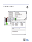
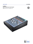
External Control of LX-300
Matrix3 Audio Show Control System
Edition: 2007-09-05 for CueStation 4.6.0
LCS SERIES
Meyer Sound Laboratories Inc
2832 San Pablo Avenue
Berkeley, CA 94702
www.meyersound.com
T: +1 510 486.1166
F: +1 510 486.8356
© 2007
Meyer Sound Laboratories Inc.
© 2007 Meyer Sound. All rights reserved.
External Control Reference
The contents of this manual are furnished for informational purposes only, are subject to change without notice, and
should not be construed as a commitment by Meyer Sound Laboratories Inc. Meyer Sound assumes no responsibility or liability for any errors or inaccuracies that may appear in this manual. Except as permitted by applicable
copyright law, no part of this publication may be reproduced, stored in a retrieval system, or transmitted, in any form
or by any means, electronic, mechanical, recording or otherwise, without prior written permission from Meyer Sound.
CueStation, CueConsole, LCS Series, Matrix3, Wild Tracks, VRAS and all alphanumeric product names are trademarks
of Meyer Sound. Meyer Sound and SpaceMap are registered trademarks of Meyer Sound Laboratories Inc. (Reg.
U.S. Pat. & TM. Off.). All third-party trademarks mentioned herein are the property of their respective trademark
holders.
Printed in the U.S.A.
Part Number: 05.164.071.01 rev.A
Table of Contents
External Control Basics
7
Message Format
Hardware Interface
Controlling Automation
11
Types of Automation Controls
Recalling Cues and Subcues
Cue List Controls
Stop, Pause, and Resume Controls
SpaceMap® Control
Controlling the Mixer
19
Setting Mixer Values
Requesting Mixer Values
SpecSpace Values
Mixer Categories, Indexes, and Values
AFL and PFL Examples
Output Relay Examples
Hardware Status Queries
27
Ping Messages
LX-300 Status and Control
Log Messages
Communication Options
31
ACK Sysex
Sysex over TCP
Sysex through a Web Server
Reference Tables
35
Fader Gain Values
Index
37
5
6
External Control Basics
Message Format
Hardware Interface
7
9
The Matrix3™ audio show control system can be controlled by external devices by sending specially formatted MIDI
messages. This chapter describes the basic structure of these messages.
Message Format
All messages to the Matrix3 hardware, regardless of the type of serial port used, utilize the MIDI System Exclusive
Protocol.
Other automation information can be found in Controlling Automation (p. 11).
All messages use the following format:
F0 (start message)
1F (LCS Audio manufacturer ID)
7E (LD-88 / LX-300 Product ID)
SUBSYSTEM (7 bit)
Frame ID (7 bit)
[Message Data] (7 bit)
CHECKSUM (7-bit)
F7 (end message)
All data bytes in the middle must be 7-bit values. The maximum size allowed for an entire single message is 512
bytes.
Subsystem Number
The SUBSYSTEM number is the ID code of the subsystem in the firmware. Examples of subsystems include:
00: SYSTEM CONTROL subsystem
01: XFER subsystem
03: RIF subsystem
10: to 1F CASL
10: MIXER subsystem
11: CUE LIST subsystem
14: sxCASLTimeSubsystem
21 - 22: ExcRec
25: External Control subsystem
36: Test subsystem
7f: Subsystem Manager
Frame ID
The Frame ID value should normally be 3F (Broadcast with checksum) for serial connections. Frame ID 7F (Broadcast
with no checksum) is used for TCP/IP. These ID settings broadcast a message to ALL LX-300s. For special commands
needing to be executed by only a single LX-300, you enter in the specific Frame ID instead. A value of 00 (hex)
corresponds to Frame ID 01.
Matrix3 systems can have up to 32 processors. For Matrix3 systems, the id range 39 (hex) to 7e (hex) is reserved
for a future development.
7
Message Format
Broadcast Messages
A Frame ID value of 3F is used to broadcast messages to all LX-300s. The message includes a checksum. Details
on calculating the checksum are in the following section.
A Frame ID value of 7F means broadcast to all LX-300s without checking the checksum field. You still must include
a dummy CHECKSUM byte in the message. The value of the checksum dummy byte should be 0.
The option for sending a message without checksum checking is only to be used by devices which are not smart
enough to calculate the checksum value. It is recommended to use the proper checksum checking whenever possible.
The exception is when using TCP/IP since the protocol includes message verification.
The message will be routed to the appropriate LX-300 specified by the Frame ID, regardless of which unit first received
the message.
Checksum
The sender calculates the CHECKSUM such that the 7 bit sum of all the values BETWEEN the first F0 and the final
F7 bytes, INCLUDING the CHECKSUM value, add up the 7 bit value 0.
To calculate the checksum, first calculate the sum of all the known 7 bit data value starting immediately after the
initial F0, and concluding with the 7 bit data value prior to the checksum. Call this value the SUM.
Then calculate the CHECKSUM value with the following C code:
CHECKSUM = (0x80 - (SUM & 0x7f)) & 0x7f;
Where '&' is a bitwise AND function.
C Language Example
Here is an example of some C code to send a 'Go Next Cue' command. Note that in the original data, the next to
last byte (00) is a placeholder for the checksum value.
typedef unsigned char uInt8;
uInt8 Message[] = {0xF0, 0x1F, 0x7E, 0x10, 0x3F, 0x09, 0x05, 0x00, 0x00, 0x00, 0x00, 0x78, 0x05, 0x00, 0xF7};
uInt8 Checksum = 0x00;
uInt8 MessageLength = 15;
uInt8 i;
for (i=1;i<MessageLength-2; i++}
{
Checksum += Message[i] & 0x7F;
}
Checksum=(0x80 -Checksum) & 0x7F; // note clearing eight bit
Message[MessageLength-2] = Checksum;
Tip
Checksum values have been included in this text for all fixed messages. For TCP/IP communication you can use
the non-checksum versions since that protocol includes message integrity checks.
A Frame ID value of 7F means broadcast to all LX-300s without checking the checksum field. A Frame ID value of
40 (hex) means send to the LX-300 with Frame ID 01 without checking the checksum field. You still must include a
dummy CHECKSUM byte in the message. The value of the checksum dummy byte should be 0.
8
Hardware Interface
Hardware Interface
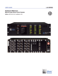
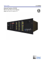
The Matrix3 hardware supports multiple simultaneous control via all ports. The CommSync module (LX-COS) has
two RS-422 ports, an RS-232 port, and MIDI In and Out. The EtherTracks module (LX-ELC) has a 10/100 base T
Ethernet port. Each LX-300 can have one LX-COS and one LX-ELC.
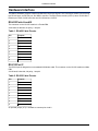
RS-422 Ports A and B
The connector on the LX-COS module is a Female DB9.
38.4K baud, 8 data bits, No parity, 1 Stop bit.
Table 1. RS-422 Cable Pinouts
Pin
Purpose
1
Shield
2
-
3
Shield
4
TxD+
5
TxD-
6
Shield
7
-
8
RxD+
9
RxD-
RS-232 Port C
The RS-232 port is designed to use a standard Null-Modem cable. The connector on the LX-COS module is a Male
DB9.
38.4 K baud, 8 data bits, No parity, 1 stop bit.
Table 2. RS-232 Cable Pinouts
Pin
Purpose
1
-
2
RxD
3
TxD
4
-
5
Ground
6
-
7
RTS
8
CTS
9
-
An optional jumper (JP1) is available to connect pins 4 and 6.
9
10
Controlling Automation
Types of Automation Controls
Recalling Cues and Subcues
Cue List Controls
Stop, Pause, and Resume Controls
SpaceMap® Control
11
12
14
16
17
Details are provided in following sections for numerous means of controlling the Matrix3 hardware. In fact, with the
information provided, it is possible to design a complete Mixer controller for any computer platform.
Types of Automation Controls
Most sound systems utilizing Matrix3 will take advantage of its CueStation™ software to set up audio mixer cues
(presets), sound effects cues, and overall show scheduling by means of a Cue List. Although Cues and Cue Lists
are programmed with CueStation software, the entire cue database resides in the internal memory of each Matrix3
within the system. Therefore, external show control systems can operate programmed shows via a direct connection
to the Matrix3 hardware. Changes made by an external control system are reflected in CueStation's user interface.
This section provides a set of recommended commands for external show control of Matrix3 systems. Message
details are provided in following sections.
Recall Cue
A Cue is addressed by a 14-bit value. The operator may want to have a panel of buttons pre-assigned for asynchronous control, such as announcements. This command does not effect the position of the active Cue List pointer.
Reset to First Cue in Active Cue List
Resets the active cue list so that the pending cue is the first cue of the list. No cue is recalled.
Go Next Cue in Active Cue List
Fires the pending cue in the cue list. The cue list pointer advances by one. For theatrical shows where the timing of
the show is driven by the actors' movements on stage, "Go Next" is the most common button used for show operation.
Skip Next in Active Cue List
This allows the pending cue to be skipped. No cue is recalled.
Skip-by-N in active Cue List
This allows the pending N number of cues to be skipped. No cue is recalled.
Skip Previous in active Cue List
This positions the Cue List pointer back by one. No cue is recalled.
Request Current Cue
This causes the hardware to reply with a message indicating the most recently recalled Cue ID.
Note
The Cue ID is a unique internal number issued when the Cue is created. It is not the position in the cue list.
Request Fader Position (System Trim)
This causes the hardware to respond with the value of the master system trim level.
11
Recalling Cues and Subcues
Set Fader Position (System Trim)
This causes the hardware to set the master system trim level to a designated value. In the case of a fire alarm, it
may be required for the show control system to interrogate the current System Trim, and set it to |-inf dB| (off). After
the fire alarm is turned off, the show control system could then restore it to its previously set value.
Recalling Cues and Subcues
Recalling Cues
Cues have a 14-bit identifier.
To recall a Cue, the following message template is used:
F0 = Start message
1F = LCS Audio manufacturers ID
7E = Matrix3 Product ID
11 = Cue List Subsystem
3F = broadcast to all LX-300s (7f broadcast no checksum)
1E = Recall Cue command.
XX = Least significant 7 bits of Cue ID
XX = Most significant 7 bits of Cue ID
XX = Calculated checksum value (use 00 if broadcast with no checksum)
F7 = End message
Note
Cues may also be recalled via Contact Closure input and MIDI Program Change messages. Consult the CueStation
4 User Manual for details. Cues are recalled within 11 milliseconds of request. CueStation user interface will be
updated to show the currently recalled Cue.
Note that the LSB and MSB must be 7 bit numbers, so the largest value possible for either LSB or MSB is 0x7f
(hexadecimal 7f). The largest possible Cue number is 0x7f 7f (decimal 16,383).
Here are some examples with the checksum calculated. (You can get CueStation to calculate the checksum for you.
Go to the Frame Control window, create a new entry of Type= Hardware Control, and Command= Raw Data. Enter
the string you want without the F0 1F 7e header or the checksum or the ending f7. Check the "Add Delimiters and
Checksum" box and look at the bottom of the window. Note that the check sum is re-calculated only when the Do
Now button is pressed, or when the check box is toggled.)
Cue Recall Examples
Recall Cue 0
F0
1F
7E
11
3F
1E
00
00
35
F7
12
Recalling Cues and Subcues
Recall Cue 1
F0
1F
7E
11
3F
1E
01
00
34
F7
Recall Cue 127
F0
1F
7E
11
3F
1E
7F
00
36
F7
Recall Cue 128
F0
1F
7E
11
3F
1E
00
01
34
F7
Recall Cue 255
F0
1F
7E
11
3F
1E
7F
01
35
F7
Recall Cue 256
F0
1F
7E
11
13
Cue List Controls
3F
1E
00
02
33
F7
Request ID of Current Cue
F0 = Start message
1F = LCS Audio manufacturers ID
7E = Matrix3 Product ID
25 = External Control Subsystem
3F = Broadcast to all LX-300s (All LX-300s will respond)
40 = Command: Get Current Cue ID
01 = Length of following data
XX = Tag Number
XX = Calculated checksum value
F7 = End message
The response of this request message is sent directly back to the requesting computer on the same serial port as
it was received. The response will contain the tag number that was in the request, so you can be sure that a response
is for you and not another system. There will be the response and then there will be an ACKnowledge message.
ACK Response Example
Request the most recently recalled Cue with a Tag Number of 01 (Checksum is 3D).
F0 = Start message
1F = LCS Audio manufacturers ID
7E = Matrix3 Product ID
25 = External Control Subsystem
3E = Reply ID code
XX = Source Frame ID
40 = Command: Get Current Cue Response
03 = Length of following response data
00 = Tag Number of Request (same as tag value in request)
XX = Least significant 7 bits of Cue ID
XX = Most significant 7 bits of Cue ID
xx = Calculated checksum value
F7 = End message
Cue List Controls
The Cue List may be controlled in the LX-300 with the following commands.
Select Cue List
F0 = Start message
1F = LCS Audio manufacturers ID
7E = Matrix3 Product ID
11 = Cue List Subsystem
3F = Broadcast to all LX-300s (Using checksum; use 7f for no checksum)
54 = Select Cue List command.
XX = Least significant 7 bits of Cuelist ID
XX = Most significant 7 bits of Cuelist ID
XX = Calculated checksum value (use 00 as placeholder if message was sent with no checksum)
F7 = End message
14
Cue List Controls
Skip to First Cue List entry
F0 = Start message
1F = LCS Audio manufacturers ID
7E = Matrix3 Product ID
11 = Cue List Subsystem
3F = Broadcast to all LX-300s
4F = Skip to first entry. Cue is not recalled.
44 = Checksum (as calculated for this message)
F7 = End message
Go Next Cue in Active Cue List
F0 = Start message
1F = LCS Audio manufacturers ID
7E = Matrix3 Product ID
11 = Cue List Subsystem
3F = Broadcast to all LX-300s
50 = Triggers the next Cue
43 = Checksum
F7 = End message
Skip to Previous Cue List Entry
F0 = Start message
1F = LCS Audio manufacturers ID
7E = Matrix3 Product ID
11 = Cue List Subsystem
3F = Broadcast to all LX-300s
4E = Skip to previous entry. Cue is not recalled.
45 = Checksum
F7 = End message
Skip to Next Cue List Entry
F0 = Start message
1F = LCS Audio manufacturers ID
7E = Matrix3 Product ID
11 = Cue List Subsystem
3F = Broadcast to all LX-300s
4D = Skip to next entry. Cue is not recalled.
46 = Checksum
F7 = End message
Show Current Cue
This command will display the current cue in the LX-300 front panel display.
F0 = Start message
1F = LCS Audio manufacturers ID
7E = Matrix3 Product ID
11 = Cue List Subsystem
3F = Broadcast to all LX-300s
52 = Show current cue command
41 = Checksum
F7 = End message
15
Stop, Pause, and Resume Controls
Show Pending Cue
F0 = Start message
1F = LCS Audio manufacturers ID
7E = Matrix3 Product ID
11 = Cue List Subsystem
3F = Broadcast to all LX-300s
53 = Show next cue command
40 = Checksum
F7 = End message
Recall Cue List Entry
F0 = Start message
1F = LCS Audio manufacturers ID
7E = Matrix3 Product ID
11 = Cue List Subsystem
3F = Broadcast to all LX-300s
1D = Recall Cue List Entry ID
XX = Least significant 7 bits of Cue List ID
XX = Most significant 7 bits of Cue List ID
XX = Least significant 7 bits of Cue List Entry ID
XX = Most significant 7 bits of Cue List Entry ID
xx = Calculated checksum value
F7 = End message
Important
The Cue List Entry IDs are not shown in the CueStation GUI. It may take some trial and error to figure out the correct
Cue Entry ID. (The Cue List Entry ID is not the same thing as the "INDEX" that is shown in the Cue List and Transport
windows.)
In most applications it would be better to recall the cue directly using the Cue ID, or to recall the next entry in a Cue
List by using the Recall Next command.
Stop, Pause, and Resume Controls
Stop All
To stop fades in progress, Wild Tracks™ hard disk playback, and SpaceMap® multichannel surround panning trajectories, the following message template is used.
F0 = Start message
1F = LCS Audio manufacturers ID
7E = Matrix3 Product ID
10 = sxMixer Subsystem
7F = Frame ID
3F = Broadcast to all LX-300s
0D = Stop command
0F = Stop command
16
SpaceMap® Control
00 = Checksum (not used with 7f but placeholder required)
F7 = End message
Cancel Fades command
F0 = Start message
1F = LCS Audio manufacturers ID
7E = Matrix3 Product ID
10 = sxMixer Subsystem
3F = Broadcast to all LX-300s (7F = broadcast with no checksum)
01
02
00 = Calculated checksum value (use 00 placeholder if broadcast with no checksum)
F7 = End message
SpaceMap Control
The LX-300s can receive external serial or MIDI data to control the panning of matrix buses by the SpaceMap algorithm. This has many applications, including parade audio localization, interactive VR development, and theatrical
audio panning.
The protocol supports assigning a given bus to a SpaceMap, and setting the location of that bus within that SpaceMap.
The "Set parameter and update host command" is used to assign the SpaceMap and the bus.
The category ID is 73 (decimal) and index 1 is the bus. Index 2 is not used. (In the following examples the value
0x7F is used for the Frame ID, thereby suppressing CHECKSUM use. Please see the Checksum entry at the front
of this manual for details.)
Assign Bus to SpaceMap Control
F0 = Start message
1F
7E
10
7F
09
49
bb = Bus number
00
00
00
mm = SpaceMap ID
00
xx = Calculated checksum value
F7 = End message
Set Bus Position
To set the position of a bus in the map.
F0 = Start message
1F = LCS Audio manufacturers ID
7E = Matrix3 Product ID
12 = SpaceMap Subsystem
7F = LX-300 ID
13 = Command
bb = Bus number
17
SpaceMap® Control
xx = First 7 bits of X coordinate
xx = Second 7 bits of X coordinate
xx = Last 7 bits of X coordinate
yy = First 7 bits of Y coordinate
yy = Second 7 bits of Y coordinate
yy = Last 7 bits of Y coordinate
n1 = Single-byte pan representation
n2 = Single-byte divergence representation
n3 = Single-byte level representation
XX = Calculated checksum value
F7 = End message
The X coordinate is represented as a little endian 21-bit value, calculated as ix = (x + 1000) * 1000
The Y coordinate is represented as a little endian 21-bit value, calculated as iy = (y + 1000) * 1000
- Pan: 1 byte (0 ... 127 -> 0.0 ... 1.0)
- Divergence: 1 byte (0 ... 127 -> 0.0 ... 1.0)
- Level: 1 byte (0 ... 127 -> 0.0 ... 1.0)
SpaceMap Example
Set the SpaceMap position for bus 3 to position (-100.5, -100.5), with pan = 0, divergence = 50%, level = full.
ix = (-100.5 + 1000) * 1000 = 899,500
iy = (-100.5 + 1000) * 1000 = 899,500
The little-endian 21 bit representation of `899,500 = 44 + (115*128) + (54*16,384)`.
Therefore: `xx xx xx` = 2C 73 36
And the full message is:
F0
1F
7E
12
7F
13
02
2C
73
36
2C
73
36
00
3F
7F
00
F7
Note
The range of control supported is -1000 to +1000 in both x and y axis.
18
Controlling the Mixer
Setting Mixer Values
Requesting Mixer Values
SpecSpace Values
Mixer Categories, Indexes, and Values
AFL and PFL Examples
Output Relay Examples
19
20
21
23
24
24
Setting Mixer Values
Set a Single Mixer Value
F0 = Start message
1F = LCS Audio manufacturers ID
7E = Matrix3 Product ID
10 = Mixer Subsystem
3F = Broadcast to all LX-300s
09 = Set Parameter command
xx = Category
xx = low 7 bits of parameter Index0
xx = hi 7 bits of parameter Index0
xx = low 7 bits of parameter Index1
xx = hi 7 bits of parameter Index1
xx = low 7 bits of Value
xx = hi 7 bits of Value
xx = Checksum
F7 = End message
See Mixer Categories, Indexes, and Values (p. 23) for descriptions of parameter values.
Set a Single Mixer Value with Fade and Wait Times
F0 = Start message
1F = LCS Audio manufacturers ID
7E = Matrix3 Product ID
10 = Mixer Subsystem
3F = Broadcast to all LX-300s
0E = Set Parameter with Fade and Wait time
xx = Category
xx = low 7 bits of parameter Index0
xx = hi 7 bits of parameter Index0
xx = low 7 bits of parameter Index1
xx = hi 7 bits of parameter Index1
xx = low 7 bits of Value
xx = hi 7 bits of Value
xx = low 7 bits of Wait Time
xx = hi 7 bits of Wait Time
xx = low 7 bits of Fade Time
xx = hi 7 bits of Fade Time
xx = Checksum
F7 = End message
19
Requesting Mixer Values
Set Multiple Mixer Values with a Fade Time
F0 = Start message
1F = LCS Audio manufacturers ID
7E = Matrix3 Product ID
10 = Mixer Subsystem
3F = Broadcast to all LX-300s
0F = Set Multiple Parameters with Fade time
xx = Category
xx = Number of points to set
For each point:
xx = low 7 bits of parameter Index0
xx = hi 7 bits of parameter Index0
xx = low 7 bits of parameter Index1
xx = hi 7 bits of parameter Index1
xx = low 7 bits of Value
xx = hi 7 bits of Value
xx = low 7 bits of Fade Time
xx = hi 7 bits of Fade Time
End of message:
xx = Checksum
F7 = End message
Note
The maximum number of messages that can be sent is 110.
Requesting Mixer Values
Requesting a Single Mixer Parameter
F0 = Start message
1F = LCS Audio manufacturers ID
7E = Matrix3 Product ID
25 = External Control Subsystem
3F = Broadcast to all LX-300s
41 = Command: Get Mix Parameter Value
06 = length of following data (or 07 if specspace byte is present)
XX = Tag Number
xx = Category
xx = low 7 bits of parameter Index0
xx = hi 7 bits of parameter Index0
xx = low 7 bits of parameter Index1
xx = hi 7 bits of parameter Index1
xx = optional SpecsSpace byte for control point
xx = Checksum
F7 = End message
See the Mixer Categories, Indexes, and Values (p. 23) section for descriptions of parameter values.
20
SpecSpace Values
Request Mixer Settings
F0 = Start message
1F = LCS Audio manufacturers ID
7E = Matrix3 Product ID
25 = External Control Subsystem
xx = Frame ID being queried - use the checksum version 0x00 to 0x3E
(All LX-300s will respond if 3F (Broadcast) is used)
42 = Command: Get Mixer Parameter Value Array
0A = length of following data (0B if SpecSpace byte is present)
00 = Place holder for Tag Number (tag number not used)
xx = Category
XX XX = Start index 0 (lsb first)
XX XX = Start index 1 (lsb first)
XX XX = End index 0 (lsb first)
XX XX = End index 1 (lsb first)
xx = Checksum
F7 = End message
The response is in the form:
F0 = Start message
1F = LCS Audio manufacturers ID
7E = Matrix3 Product ID
25 = External Control Subsystem
3E = Reply ID code
XX = Source Frame ID (ID of replying LX-300)
42 = Command: Mixer Parameter Value Array
XX = Length of Following Response Data
...
data bytes go here
...
XX = Checksum
F7
SpecSpace Values
SpecSpace values were added as a way to increase the number of Mixer Categories from 128 to 16,384 (128 categories x 128 SpecSpaces).
The response of this request message is sent directly back to the requesting computer on the same serial port as
it was received.
Response Using SpecSpace Value
F0 = Start message
1F = LCS Audio manufacturers ID
7E = Matrix3 Product ID
25 = External Control Subsystem
3E = Reply ID code
XX = Source Frame ID
41 = Command: Get Mixer Parameter Value
08 = Length of following response data (09 if SpecSpace byte is present)
XX = Tag number of request
xx = Category
xx = low 7 bits of parameter Index0
xx = hi 7 bits of parameter Index0
21
SpecSpace Values
xx = low 7 bits of parameter Index1
xx = hi 7 bits of parameter Index1
xx = low 7 bits of Value
xx = hi 7 bits of Value
xx = optional control point SpecSpace byte
xx = Checksum
F7 = End message
Some categories include many parameters, either indexed by INDEX0, INDEX1 or both indexes.
To request a single dimension array of these parameters, the following template is used:
F0 = Start message
1F = LCS Audio manufacturers ID
7E = Matrix3 Product ID
25 = External Control Subsystem
XX = Frame ID (or broadcast using 3F)
42 = Command: Get Mixer Parameter Value Array
0A = length of following data
(0B if SpecSpace byte is present)
XX = Tag Number
xx = Category
XX XX = Start index 0 (lsb first)
XX XX = Start index 1 (lsb first)
XX XX = End index 0 (lsb first)
XX XX = End index 1 (lsb first)
xx = optional SpecSpace byte
xx = Checksum
F7 = End message
You can request values along either dimension on only one index.
Therefore, Start Index 0 and End Index 0 must be equal, or Start Index 1 and End Index 1 must be equal.
You can request a MAXIMUM of 32 parameters at a time.
See the Mixer Categories, Indexes, and Values (p. 23) section below for description of CATEGORY, INDEX0,
INDEX1, and VALUE.
The response of this request message is sent directly back to the requesting computer on the same serial port as
it was received.
The response is in the form:
F0 = Start message
1F = LCS Audio manufacturers ID
7E = Matrix3 Product ID
25 = External Control Subsystem
3E = Reply ID code
XX = Source Frame ID
42 = Command: Get Mixer Parameter Value Array
XX = Length of Following Response Data
XX = Tag Number of Request
XX = Parameter Category
XX XX = Start Index0 (LSB first)
XX XX = Start Index1 (LSB first)
XX XX = End Index0 (LSB first)
XX XX = End Index1 (LSB first)
...
XX XX = Up to 32 requested values. LSB first.
xx= SpecSpace byte (optional)
22
Mixer Categories, Indexes, and Values
...
XX = Checksum
F7
Mixer Categories, Indexes, and Values
Category is a single 7-bit value. Categories specify groups of parameters of the same type, for example all Input
Volumes are in one category, and all Output EQ Q Values are in another category.
Index0, Index1, and Value are all 14-bit integers.
The meaning of Value depends on the category. Different categories can require values in the following forms:
Boolean. On/off for switches, such as polarity and bus assigns. 0 = off 1 = on
Fader. Value for normal fader gains. Range: 0 to 1000 (decimal). Value is in 0.1 millimeters of fader position. A
value of 760 (decimal) corresponds to 0 db gain (unity). A value of 0 corresponds to negative infinity gain (all the
way off).
Faders are controlled externally by setting their position along the fader travel, rather than in raw dB. The fader taper
is piecewise linear.
Panpot. Value of pan control. Value of 63 (decimal) means center Minimum value of 0 means full LEFT Maximum
value of 127 means full RIGHT
Delay Time. Value is in 10ths of a millisecond. Minimum value is 0 Maximum value is 4900 milliseconds for outputs/Aux Outputs Maximum value is 1700 milliseconds for inputs.
EQ Gain. Offset of Value is 200 (decimal) Value of 200 (decimal) means GAIN of 0 dB Minimum value is 0
(decimal), which is GAIN of -200 dB Maximum value is 400 (decimal), which is GAIN of +200 db
EQ Type. Value can be: 0 = Low Shelf 1 = Bandpass/Band Reject 2 = Hi Shelf
EQ Frequency. Value is in Hertz scaled by 2 Value of 0 corresponds to 0 Hz. Value of 1000 (decimal) corresponds
to 2000 Hz Maximum value of 12000 (decimal) corresponds to 24000 Hz
EQ Q Value. Value is scaled by 0.01 (decimal) Value of 100 (decimal) is Q value of 1.00 (decimal) Minimum value
is 50 (decimal), which is Q = 0.5 Maximum value is 9999 (decimal), which is Q = 99.99
Fade Time. seconds
Value is in tenths of a second. Minimum value is 0 Maximum value is 16383, corresponding to 1,638
Wait Time. Value is in tenths of a second. Minimum value is 0 Maximum value is 16383, corresponding to 1,638
seconds
Group ID. Minimum value is 0 Maximum value is 64 (decimal)
Example: Setting System Trim to Unity
To set the System Trim you can use the fade table to determine the value to send. You can test this and get
CueStation to calculate the Checksum for you by using "Type=Hardware Control, Command=Raw Data" in the
Frame Control window.
System Trim to Unity
F0 = Start message
1F = LCS Audio manufacturers ID
7E = Matrix3 Product ID
10 = Mixer Subsystem
3F = Broadcast to all LX-300s with Checksum
(use 7f for Broadcast with no checksum)
09 = Set Parameter command
05 = Category ID for System Trim
00 = low 7 bits of parameter Index0
00 = hi 7 bits of parameter Index0
00 = low 7 bits of parameter Index1
23
AFL and PFL Examples
00 = hi 7 bits of parameter Index1
78 = low 7 bits of Value
05 = hi 7 bits of Value
09 = Checksum (use 00 as placeholder if Broadcast with no checksum is used)
F7 = End message
So all you need to type into the Raw Data command is: 10 3f 09 05 00 00 00 00 78 05
When you check the "Add Delimiters and Checksum" box, the hex at the bottom of the window will update to show:
f0 1f 7e 10 3f 09 05 00 00 00 00 78 05 09 f7
If you click "Do Selected", then you will see your System Trim jump to Unity.
AFL and PFL Examples
This section describes parameters for the AFL and PFL control points.
Input PFL. specspace = sxParamSpecspace (0x00)
category = cpInputPFL (0x7C)
index0 = input channel #
index1 = 0 (unused)
value = 1 to set, 0 to unset
Output AFL. specspace = sxParamSpecspace (0x00)
category = cpOutputAFL (0x7D)
index0 = output channel #
index1 = AFL # (0 is first AFL, 1 is second AFL)
value = 1 to set, 0 to unset
AuxOut PFL. specspace = sxParamSpecspace (0x00)
category = cpAuxOutAFL (0x7E)
index0 = aux channel #
index1 = AFL # (0 is first AFL, 1 is second AFL)
value = 1 to set, 0 to unset
PFL Exclusive-mode Toggle. specspace = sxExtendedSpecspace (0x06)
category = exPFLExclusive (0x01)
index0 = 0 (unused)
index1 = 0 (unused)
value = 1 for exclusive (radio button) mode
0 for non-exclusive (pile-on) mode
Output Relay Examples
Audio output relays on the A0-8 modules can be muted with an external control message. Subsystem 0x35, command
0x04 is "OPEN AUDIO RELAY".
Its length must be 1, with the one data byte being the slot (0=A, 1=B, 2=C). You can also use command 0x03 to
close the relays on a slot.
For Frame ID 01, slot C:
Open Relay. 24
Output Relay Examples
f0
1f
7e
35
00
04
01
02
28
f7
Close Relay. f0
1f
7e
35
00
03
01
02
28
f7
25
26
Hardware Status Queries
Ping Messages
LX-300 Status and Control
Log Messages
27
28
29
How to get information about the Matrix3's status.
Ping Messages
The Ping command is used to determine the basic status of a processor within a Matrix3 system. The status reply
includes two 7-bit values, "UserValue1" and "UserValue2", which both default to 0. These are optional values and
do not need to be set unless you want your own user values. For instance, they may be used to designate a show
project file version number.
The following command may be sent to any LX-300 in a system via a serial or TCP/IP port. The Ping Response is
sent on the same serial port as the ping was received on.
Ping Request
F0 = Start message
1F = LCS Audio manufacturers ID
7E = Matrix3 Product ID
7F = Manager Subsystem
3F = Broadcast to all LX-300s (only receiving LX-300 will respond)
44 = Ping Command
00 = length of following data
61 = Checksum as calculated for this message
F7 = End message
Ping Response
F0 = Start message
1F = LCS Audio manufacturers ID
7E = Matrix3 Product ID
7F = Manager Subsystem
3E = Reply ID code
XX = Source Frame ID
44 = Ping Command Response
0f = Data length, 15 bytes
XX = UserValue 1
XX = UserValue 2
XX = back panel ID value setting
XX = single box mode flag
XX = number of LX-300s in network
XX = Wild Tracks enabled flag
XX XX XX XX = 4 char ASCII version number of main firmware code
XX XX XX XX = 4 char ASCII version number of SCSI firmware code
XX = configuration flag: 0x01=LX-300 has valid configuration, 0x00= LX-300 has no configuration.
XX = checksum
F7 = End message
Set User Ping Status
This is an optional user status value. Value 1 and value 2 are not required and default to zero.
27
LX-300 Status and Control
F0 = Start message
1F = LCS Audio manufacturers ID
7E = Matrix3 Product ID
7F = Manager Subsystem
3F = Broadcast to all LX-300s (only receiving LX-300 will respond, use 7f broadcast, no checksum)
08 = Ping Command
02 = length of following data
00 = UserValue1
00 = UserValue2
XX = Checksum (example: 1B for UserValue1&2 set to 00)
F7 = End message
LX-300 Status and Control
Request Memory Status
F0 = Start message
1F = LCS Audio manufacturers ID
7E = Matrix3 Product ID
00 = System Control Subsystem
XX = Frame ID, (00=Frame ID 01, 3F= Broadcast to all LX-300s)
03 = Request Memory Status command
00 = Command argument count
xx = Checksum
F7 = End message
Request Firmware Version
F0 = Start message
1F = LCS Audio manufacturers ID
7E = Matrix3 Product ID
00 = System Control Subsystem
XX = Frame ID, (00=Frame ID 01, 3F= Broadcast to all LX-300s)
04 = Request Firmware Version command
00 = Command argument count
xx = Checksum
F7 = End message
Request Temperature
F0 = Start message
1F = LCS Audio manufacturers ID
7E = Matrix3 Product ID
00 = System Control Subsystem
XX = Frame ID, (00=Frame ID 01, 3F= Broadcast to all LX-300s)
0A = Request Temperature Status command
00 = Command argument count
xx = Checksum
F7 = End message
Set LX-300 Front Panel Message
F0 = Start message
1F = LCS Audio manufacturers ID
7E = Matrix3 Product ID
00 = System Control Subsystem
28
Log Messages
XX = Frame ID, (00=Frame ID 01, 3F= Broadcast to all LX-300s)
00 = Subsystem ID
01 = Command ID
XX = Number of bytes in text
XX XX XX... = Data bytes
XX = Checksum
F7 = End message
Log Messages
Each LX-DSP and LX-EXP maintains an internal debug log. The system can be set to store a number of types of
messages including plugin and alerts. Each module uses 256K of memory for the log. The command uses two
parameters, the beginning and ending index. If the beginning index is 0x7F, then it clears the memory. To print them
all out, use 0x00 to 0x7E for the indexes.
Some useful index values:
• 00: All log messages that go to the log window.
• 01: Beginning debug messages, and all DEBUG logs (mostly everything)
• 02: A lot of plugin messages.
Print Log Messages
F0 = Start message
1F = LCS Audio manufacturers ID
7E = Matrix3 Product ID
00 = (Sys Subsystem #)
XX = Frame ID, (00=Frame ID 01, 3F= Broadcast to all LX-300s)
23 = (Print Debug command)
02 = (length in bytes)
XX = (Beginning index. 0x7F to clear the messages)
XX = (Ending index)
XX = checksum
F7 = End message
29
30
Communication Options
ACK Sysex
Sysex over TCP
Sysex through a Web Server
31
33
34
Different ways of communicating with the Matrix3s.
ACK Sysex
This feature allows you to "wrap" any other sysex that you send to any LX-300 DSP inside a "please-ack-me"
wrapper sysex, so that you can get an acknowledgement for the sysex without having to mess around with masterport stuff (and without getting spammed by acks for less important sysexes)
The format for the sysex wrapper is this:
F0
1F
7E
25 = sxExternalControlSubsystem
XX = destination DSP IDs, or broadcast (7f broadcast, no checksum) Who gets the COMMAND
06 = EXTSUB_CMD_ACK_WRAPPER
XX = DSP ID indicating which DSP(s) should send acks (frame id 01 = 00) WHO ACKS
XX XX XX XX XX = 5-byte tag-value, will be copied into the ack
(set by the user for what ever value they want to put in here – must be 7-bit clean)
[...] = Insert the main sysex here (omit the F0, Checksum, and F7)
xx = Checksum (a 00 place holder required if no checksum.)
F7
Important
The 5-byte tag value must be 7bit clean. This means that each byte must be in the range of 00 to 7f inclusive. (this
is the same range for all data bytes in CASL)
ACK
The format of the ACK sysex that is sent back in response is this:
F0
1F
7E
25 = sxExternalControlSubsystem
3E = MDSUBSYS_REPLY_ID
XX = Source DSP ID (i.e. the DSP that sent the ack)
44 = EXTSUB_CMD_ACK_REPLY
XX XX XX XX XX = 5-byte tag value, as specified in original sysex
xx = Checksum
F7
Example 1: Check Frame ID 01 Firmware
Say you wanted to send a "Check Firmware Version" sysex to all LX-300s, and you want an ACK back just from
Frame ID 01. Here is what you could send:
31
ACK Sysex
F0
1F
7E
25 = sxExternalControlSubsystem
7F = Broadcast to all LX-300s
06 = EXTSUB_CMD_ACK_WRAPPER
00 = Frame ID 01 (the only processor we want an ack from)
01 02 03 04 05 = tag-value (can be anything I like, I chose 1,2,3,4,5)
1f 7e 00 3f 04 00 = embedded "check firmware version" payload sysex
xx = Checksum
F7
When you send the above sysex, you should see all the DSPs print their firmware version to the log, and then immediately afterwards you should receive back the following sysex from DSP 0:
Firmware Response
F0
1F
7E
25 = sxExternalControlSubsystem
3E = MDSUBSYS_REPLY_ID
00 = Source DSP: Frame ID 01 sent the ack
44 = EXTSUB_CMD_ACK_REPLY
01 02 03 04 05 = 5-byte tag value, as sent in original sysex
xx = Checksum
F7
Note that the "DSP ID indicating which DSP(s) should send acks" byte can be set to an explicit DSP ID (as shown
above), or it can be set to 0x3F/0x7F (i.e. broadcast) if you want acks from all DSPs, or it can be set to 0x3B
(BOXNET_LOCAL_DSP) to indicate that the ack should come from the DSP where the serial port is physically
connected, regardless of that DSP ID.
Set Client Type
If the client is connecting via lxtcpcomd, it must send a set-client-type sysex to get any sysexes back from lxtcpcomd.
However, there is a nice fine-grained way to tell lxtcpcomd exactly which sysexes your client wants to see.
Here is how to do it:
Send a sysex to lxtcpcomd tell it you are a client of type LXTCP_FORWARD_CUSTOM, by sending this sysex:
f0
1f
7e
30 = sxTCPSubsystem
7f = broadcast
00 = LXTCP_CONTROL_COMMAND_SET_CLIENT_TYPE
02 = LXTCP_FORWARD_CUSTOM
00 = unused
00 = unused
xx = Checksum
f7
Send one or more LXTCP_CONTROL_COMMAND_ADD_CUSTOM_PARSE_PREFIX sysexes to lxtcpcomd. Each
of these sysexes contains a sysex prefix -- any time lxtcpcomd sees a sysex that starts with these bytes, it will forward
it to your client.
32
Sysex over TCP
f0
1f
7e
30 = sxTCPSubsystem
7f = broadcast
0F = LXTCP_CONTROL_COMMAND_ADD_CUSTOM_PARSE_PREFIX
[...] = prefix bytes of desired sysex, not including F0
xx = Checksum
f7
EXAMPLE: if all your client cares about is the EXTSUB_CMD_ACK_REPLY sysexes generated above, it could send
the following sysexes to lxtcpcomd to indicate that:
Client Type is LXTCP_FORWARD_CUSTOM
f0
1f
7e
30
7f
00
02
00
00
CK
f7
Send all sysexes that start with "F0 1F 7e 25 3E 00 44"
f0
1f
7e
30
7f
0F
1F
7E
25
3E
00
44
CK
F7
RS-232 and RS-422 ACK Details
When connected via serial, you will only get an ack back from the LX-300 you are physically connected to. The
other LX-300s will generate acks if the wrapper asks them to, but the routing to get those acks back to the correct
LX-300's serial port is not implemented. Use 0x3B (BOXNET_LOCAL_DSP) as the DSP ID for sending ACK when
connected via serial.
When connected via lxtcpcomd (Ethernet), you can get acks back from any or all DSPs.
Sysex over TCP
To use the EtherTracks module as if it were a very fast serial port, have your control program make a TCP connection
to port 2980 of the EtherTracks card. Once the TCP connection is established, you may immediately begin sending
MIDI sysex control messages to the LX-300, as documented elsewhere.
33
Sysex through a Web Server
By default, however, you won't get any reply or other sysexes back over the TCP connection. This is because different
software connects to the server for different purposes, and so needs to get different data back. Rather than spam
every client with every sysex, the server sends nothing back by default, unless/until you send it a sysex telling it
what sort of messages you want back. Each client may change his filter type at any time by sending this sysex.
Please note that filters cannot be combined - you can only switch between them.
Client Type Announcement
f0 = Begin sysex byte
1f = LCS manufacturer ID
7e = LD88/LX300 product ID
30 = sxTCPSubsystem byte
3f = Broadcast to all LX-300s (this byte is ignored, actually)
00 = Set-client-type command code (tcpSetClientType)
XX = Client filter type (see below)
00 = Client Index (generally this should be set to zero)
00 = Client Sub-index (generally this should be set to zero)
XX = Checksum byte
f7 = End sysex byte
The only decision to make above is the value to supply in the "client type" byte. Currently the supported values for
this byte are:
• 0 : (LXTCP_FORWARD_NOTHING) - Default mode. No messages are ever sent to you.
• 2 : (LXTCP_FORWARD_CUSTOM) - Set the types of messages you want to receive.
• 3 : (LXTCP_FORWARD_EVERYTHING) - Spams you with every message type, no matter what
Sysex through a Web Server
The EtherTracks module has a web server to support a connections from web browsers. This can be used to view
LX-300 status data, or to send any sysex message to the LX-300.
For example, if your EtherTracks card is at IP address 192.168.0.101, you could type this into your web browser:
http://192.168.0.101/sysex?1f,7e,11,3f,1C,00,00
And press return, and it would cause the LX-300s to recall cue zero.
It is possible to create an HTML page full of links like this:
<a href="http://192.168.0.101/sysex?1f,7e,11,3f,1C,00,00">Recall Cue 0</a>
And show that in your web browser, and you would have a rudimentary control panel. Clicking on each link would
fire a different sysex.
With Javascript, you could do even more elaborate things.
Format for the URL is as shown above. F0, checksum, and F7 are optional (they will be added automatically if you
don't put them in). Values are in hexadecimal, comma separated.
The LX-300 will respond to the command and you will see the sent sysex in your browser. You can use “Small
Status” to see the current status of the LX-300.
34
Reference Tables
Fader Gain Values
35
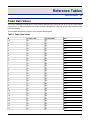
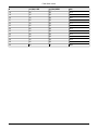
Fader Gain Values
The LX-300 maintains a lookup table of 1001 points to describe every level in dB from off to +10 dB. These values
(ranging from 0 to 1000) are packed "little endian" with the least significant 7 bits first, and the most significant 3 bits
in the second byte.
The next table describes the values to set to achieve different gains.
Table 3. Fader Gain Values
B
xx (Hex) LSB
yy (Hex) MSB
mm
10
68
07
100
9
50
07
97.6
8
38
07
95.2
7
20
07
92.8
6
08
07
90.4
5
70
06
88.0
4
58
06
85.6
3
40
06
83.2
2
28
06
80.8
1
10
06
78.4
78
05
76.0
1
60
05
73.6
2
48
05
71.2
3
30
05
68.8
4
18
05
66.4
5
00
05
64.0
6
68
04
61.6
7
50
04
59.2
8
38
04
56.8
9
20
04
54.4
10
08
04
52.0
11
7D
03
50.8
12
70
03
49.6
13
64
03
48.4
14
58
03
47.2
15
4C
03
46.0
16
40
03
44.8
17
34
03
43.6
35
Fader Gain Values
B
xx (Hex) LSB
yy (Hex) MSB
mm
18
28
03
42.4
19
1C
03
41.2
20
10
03
40.0
21
04
03
38.8
22
78
02
37.6
23
6C
02
36.4
24
60
02
35.2
25
54
02
34.0
26
48
02
32.8
27
3C
02
31.6
28
30
02
30.4
29
24
02
29.2
30
18
02
28.0
36
Index
A
AFL, 24
automation
cue lists, 14-16
cues, 12-14
SpaceMap, 17-18
stop, 16
C
checksum, 8
client type, 32-34
E
examples
ACK response, 14, 31
check firmware, 31
HTML sysex links, 34
recalling cues, 12-14
using C, 8
F
fader gain values, 35
Frame IDs, 7
H
hardware
ports, 9
L
log messages, 29
LX-300
broadcasts, 8
status, 28-29
M
mixer
requesting values, 20-21
setting values, 19-20
Mixer categories, 23-24
P
PFL, 24
ping, 27
processor (see LX-300)
R
Relays, 24
RS-232, 9
ACK response, 33
RS-422, 9
ACK response, 33
37
S
subsystem
numbers, 7
sysex
requesting ACK response, 31
standard message format, 7
through a web server, 34
through TCP, 33
38