1
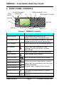
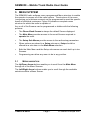
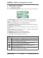
SRM9030
Mobile Radio
Trunk
Operating Instructions
TNM-U-E-0004
May 2001
SRM9030 ~ Trunk Mobile Radio User Guide
WARNINGS
1. Do NOT use your radio when driving a vehicle.
2. Do NOT operate your radio in an explosive atmosphere.
Obey the 'Turn Off Two-way Radios' signs where these are posted.
3. Do NOT touch the antenna while the radio is transmitting.
TNM-U-E-0004
Page 1
© Simoco Europe 2001
SRM9030 ~ Trunk Mobile Radio User Guide
Using the Radio
Follow these hints for clear speech transmission and maximum battery life
•
When speaking, hold the portable (or microphone speaker) a few
centimeters from your mouth and speak across it, rather than into it.
•
Keep the length of your conversation to a minimum.
•
Replace the microphone on its cradle after use.
•
Avoid making calls from known poor signal-strength areas such as the
radio systems fringe areas (limit of range) or from screened areas –
e.g. underground car park or underpass.
•
To avoid unnecessary drain on the vehicle battery, keep the engine
running when making long calls.
About This Document
Due to our policy of continuous improvement of our products and services,
technical specifications and claims, correct at time of publication, may be
subject to variation without prior notice.
Simoco has endeavoured to ensure that the information in this document is
fairly stated , but does not accept liability for any errors or omissions.
This publication is copyright and no part may be reproduced without prior
permission of Simoco Europe Ltd.
TNM-U-E-0004
Page 2
© Simoco Europe 2001
SRM9030 ~ Trunk Mobile Radio User Guide
CONTENTS
USING THE RADIO
2
ABOUT THIS DOCUMENT
2
1. INTRODUCTION
5
1.1 Installation ....................................................................................5
1.2 In the Event of Difficulty................................................................5
2. FRONT PANEL CONTROLS
6
3. MENU SYSTEM
7
3.1 Menu navigation ...........................................................................7
4. MAIN MENU SCREENS
9
4.1 Phonebook Screen .......................................................................9
4.2 Stored Calls Screen....................................................................10
4.3 Recall Screen .............................................................................12
4.4 Status Screen .............................................................................12
4.5 Call Types Screen ......................................................................13
4.6 Setup Screen..............................................................................13
5. COMMON FUNCTIONS AND FACILITIES
14
5.1 Switch-On/Switch-Off..................................................................14
5.1.1
In-Service Indication.....................................................14
5.1.2
Volume Adjustment ......................................................14
6. CALL TYPES
15
6.1 Making a Voice Call....................................................................16
6.1.1
During a Voice Call ......................................................17
6.2 Making a Status Call...................................................................18
6.2.1
Using the Phonebook ...................................................18
6.2.2
By Dialling the Numbers...............................................18
6.3 Receiving a Call..........................................................................19
6.3.1
Receiving a Voice Call .................................................19
6.3.2
Receiving a Group Voice Call ......................................20
6.3.3
Incoming Status and Data Messages...........................20
6.4 Call Diversion .............................................................................21
6.4.1
From the Call-Types Screen ........................................21
6.4.2
By Dialling the Numbers...............................................21
6.4.3
To Cancel a Diversion ..................................................21
6.5 DTMF Operation .........................................................................22
TNM-U-E-0004
Page 3
© Simoco Europe 2001
SRM9030 ~ Trunk Mobile Radio User Guide
6.6 External alert...............................................................................22
7. SETUP
23
7.1 Setup Sub Menus .......................................................................23
7.1.1
User Options.................................................................23
7.1.2
Group............................................................................24
7.1.3
Phone Book Edit...........................................................24
7.1.4
Contrast ........................................................................26
7.1.5
Alert Volume .................................................................26
7.1.6
Information ...................................................................26
7.1.7
Network ........................................................................26
APPENDIX A - ALERT TONES AND MESSAGES
27
APPENDIX B - DIAL STRINGS AND NUMBERING CONVENTIONS
29
APPENDIX C - GLOSSARY
31
TNM-U-E-0004
Page 4
© Simoco Europe 2001
SRM9030 ~ Trunk Mobile Radio User Guide
1. INTRODUCTION
The SRM9000 Series Radios are versatile Digital Signal Processor (DSP)
controlled, two-way mobile radios. The SRM9000 Series is available in a
number of frequency bands and versions for specific applications. This
manual describes the operation of the SRM9030 Trunk Alphanumeric
Display variant.
The radio consists of a Transceiver unit that may be mounted in the vehicle
boot or under a seat, and an Alphanumeric Control Unit which is designed
to mount on the vehicle console or within view and reach of the driver. A
microphone and speaker connected to the radio provide the audio interface.
The radio is software programmable and it can be customised to the
operational requirements of your particular fleet. Your Simoco
representative can help in programming your radios facilities to meet your
present and future requirements.
This guide describes the facilities that are currently available and can be
programmed into the SRM9030.
1.1
INSTALLATION
The SRM9030 Mobile Transceiver can be installed and set up for use by
your dealer. As the installation is a technical and possibly hazardous
operation, we do not recommend that you do it yourself. However, if you
need information regarding the correct procedures for installation, please
refer to the SRM9030 Installation Sheet supplied with the radio.
1.2
IN THE EVENT OF DIFFICULTY
If the radio fails to switch on, check that:
•
the fuse has not blown,
Your dealer should advise you of the location of the fuse,
•
the power supply cables and connections are secure, and
•
the vehicle battery is charged.
If these checks are OK, contact your dealer for further advice.
TNM-U-E-0004
Page 5
© Simoco Europe 2001
SRM9030 ~ Trunk Mobile Radio User Guide
2. FRONT PANEL CONTROLS
PUSH
ON/OFF
POWER/TRANSMIT
INDICATOR
F2
GREEN HANDSET (CALL)
F1
RED HANDSET (CLEAR)
VOLUME
F5
KEYPAD
DISPLAY
F3
F4
MENU
↕
SCROLL ↔
Figure 1 – SRM9030 Controller
Button/ Control
Function
On/Off/Volume
Push to switch the radio On or Off.
Rotate to set volume to the desired level.
Rx/Tx/Power LED
Green LED illuminates at power On. Red LED
Illuminates when the radio is transmitting.
Green Handset
Used to place a call to the displayed identity.
Red Handset
Used to end a call, backspace /Clear
dialstrings entries and return to the Main
Menu Screen.
Keypad
Used to dial numbers, and insert dialstrings.
Scroll Up/Down
Scroll between Menu Screens.
Scroll Left/Right
Scroll through lists (within a Menu Screen).
Function Button F1
Function Button F2
Function Button F3
Function Button F4
Special Function F5
These buttons are programmable to perform
different functions according to the menu that
has been accessed.
Displayed labels indicate button function.
This button is programmable for a special
operation.
Special Function F6 On top This button is programmable for a special
of Mic. operation.
TNM-U-E-0004
Page 6
© Simoco Europe 2001
SRM9030 ~ Mobile Trunk Radio User Guide
3. MENU SYSTEM
The SRM9030 radio software uses a programmed Menu structure to enable
the operator to access all of the radio options. The structure of the menu
(comprising up to thirteen screens) can be programmed to meet the specific
needs of individual customers. Figure 2 illustrates a complete menu
structure for which the radio is capable of.
Any or all of the Screens can be programmed or hidden with the following
provisos:
•
The Phone Book Screen is always the default Screen displayed.
•
The Main Menu provides access to the usual Screens required to
operate the radio.
•
The Setup Sub Menus provide access to the radio setup parameters.
•
When options are placed in a Setup sub-menu, Setup should be
offered as a sub menu in the Main Menu selection.
•
Both the Main Menu and the Setup sub-menus can each hold up to ten
Screens.
•
Programming can allow any menu to be in any position.
3.1
MENU NAVIGATION
The Up/Down Arrow buttons enable you to scroll from the Main Menu
through all of the Menu Screens.
The Left/Right Arrow buttons enable you to scroll through the available
selections within a Menu Screen.
TNM-U-E-0004
Page 7
© Simoco Europe 2001
SRM9030 ~ Mobile Trunk Radio User Guide
Menu System
Press the Red Phone
to return to the Main
From any other
Setup
SubMenus
Main Menu
Lists Users
= Up/Down Scroll
b tt
= Left/Right Scroll
Phone
Book
ID and Name
User
Options
Missed Voice Calls
Received Status Messages
Received Data Messages
Keybeeps
Display Illumination
DTMF
Stored
Calls
Group
Show
Group
Membership
Call Types
Phone
Book
Edit
Change
Phone book
Entries
Last 8 Calls Placed
(last first)
Recall
Contrast
List of assigned
outgoing
Status Messages
Status
Alert
Volume
Setup
Information
Voice Calls
Priority & Emergency Calls
Status Calls
Diversion Calls
Include Calls
Etc.
OK
or
Network
Adjust
Display Contrast
Beep Tone
level setting
Programmer File description
SW Version
Trunk ID
Radio Serial No.
Trunk Network 1/2
or
Conventional Channel
Selection
Figure 2 - Menu Navigation
TNM-U-E-0004
Page 8
© Simoco Europe 2001
SRM9030 ~ Mobile Trunk Radio User Guide
4. MAIN MENU SCREENS
4.1
PHONEBOOK SCREEN
The Phonebook allows calls to be made to entries from the Phonebook list.
ICONS
LABEL 1
LABEL 2
Name Field
MESSAGE LINE
LABEL 3
LABEL 4
The Name Field shows the current selected entry from the Phonebook.
Press the Left/Right Arrow buttons to scroll through the Name Field
entries.
Press the Green Handset to call the Name Field entry.
The Message Line provides information about what the radio is doing, e.g.
Call-setup, Queued, Diverted, etc.
The RSSI Bars indicate the signal strength of the current Control or Traffic
channel.
Displayed Labels show the function of the F1…F4 buttons. Pressing one of
these buttons will execute the function.
The Keypad may be used to enter dialstrings directly.
The Up/Down Arrow buttons go to other Menu Screens.
Several Icons can be displayed as shown below:
ICONS
The rotating arrow icon shows that the radio is registering with
the Trunk Network. It disappears when the radio is in-service.
The envelope icon indicates that there are one or more stored
calls, (in the Stored Calls screen).
The outline speaker icon indicates that speaker audio is
muted, e.g. during Call Setup, NPDs, etc.
The solid speaker icon indicates that speaker audio is
enabled, eg during a Call.
*
This icon indicates Call Pending, i.e. there is an outgoing call
waiting for the radio to be In-Service.
TNM-U-E-0004
Page 9
© Simoco Europe 2001
SRM9030 ~ Mobile Trunk Radio User Guide
4.2
STORED CALLS SCREEN
This screen allows missed Voice calls (and received Status and Data
messages) to be reviewed.
The
icon will show in the Main Phonebook Screen when there is an
entry in this Screen. A "Bip" tone is emitted every few seconds when a new
call or message is stored.
Three different types of call can be stored. The screen display will change
depending on the type of call stored.
Stored Calls
Missed Voice Call
Delete
Voice
John
#05
OK
Stored Calls
Received Status Message
Status
Delete
John
At Lunch
#04
OK
Received Data Message
Stored Calls
Delete
Data
John
#03
More
TNM-U-E-0004
Page 10
© Simoco Europe 2001
SRM9030 ~ Mobile Trunk Radio User Guide
The displayed number (#05) shows the queued position of the entry.
The most recent call is shown whenever this Screen is displayed.
•
Press Left/Right Arrow buttons to scroll through other stored calls.
•
Press the Green Handset to Voice Call the originator.
•
Press the Red Handset to return to the Phonebook Screen without
making a call.
•
Press
Screen.
•
Press
to go to the Phonebook Screen with the Call Dialstring
ready for editing, the keypad is enabled for this step.
to delete the viewed entry and return to the Phonebook
When a Data call is stored the first 14
characters of the Data Message are
displayed. Press
More to display
the full message (up to 100 characters).
TNM-U-E-0004
Page 11
© Simoco Europe 2001
SRM9030 ~ Mobile Trunk Radio User Guide
4.3
RECALL SCREEN
Use this Screen to review any of the last
eight recently placed calls.
Recall
#01
Delete
John
OK
•
Press the Left/Right Arrow buttons to scroll through the Recall list.
•
Press the Green Handset to Voice call the originator
•
Press the Red Handset to return to the Phonebook Screen without
making a call.
•
Press
Screen.
•
Press
to go to the Phonebook Screen with the Call Dialstring
ready for editing, the keypad is enabled for this step.
4.4
to delete the viewed entry and return to the Phonebook
STATUS SCREEN
Status
Use this Screen to view and send Status
Messages from the programmed list.
The screen will always open at the last
viewed message.
Gone Home
*021*
OK
•
Press the Left/Right Arrow buttons to scroll through the Status list.
•
Press the Green Handset to Send the displayed Status
•
Press the Red Handset to return to the Phonebook Screen without
making a call.
•
Press
to go to the Phonebook Screen with the Status Message
Dialstring ready for editing, the keypad is enabled for this step.
TNM-U-E-0004
Page 12
© Simoco Europe 2001
SRM9030 ~ Mobile Trunk Radio User Guide
4.5
CALL TYPES SCREEN
Use this Screen to make different types
of calls.
Call Types
Divert
*41*
OK
•
Press the Left/Right Arrow buttons to scroll through the available call
types.
•
Press the Green Handset to make the special call to the current
Phonebook identity.
•
Press the Red Handset to return to the Phonebook Screen without
making a call.
•
Press
to go to the Phonebook Screen with the Call-Type modifier
ready for editing, the keyboard is enabled for this step.
4.6
SETUP SCREEN
Use this Screen to access the other
Setup submenus.
Setup
OK
•
Press
or the Left/Right Arrow buttons to show the first of the
submenus, and then the Up/Down Arrow buttons to scroll these
screens.
See Section 7 for further information.
TNM-U-E-0004
Page 13
© Simoco Europe 2001
SRM9030 ~ Mobile Trunk Radio User Guide
5. COMMON FUNCTIONS AND FACILITIES
5.1
SWITCH-ON/SWITCH-OFF
Momentarily press the On/Off/Volume
Knob to switch the radio ON.
The display will illuminate and show a
SRM90000
‘Welcome Message’ and the Trunk
201-2001-20
Identity of the radio.
After a brief time the display will revert to
the Phonebook Screen, at which time
the radio is ready for use.
Pressing and holding the On/Off knob for approximately 2s will switch the
radio Off.
If the radio Inactivity Timer is enabled,
Depot
the radio will automatically turn Off after
several hours of inactivity (i.e. no
buttons pressed). The radio will emit
FREDRICK
warning beeps for 10 seconds prior to
DTMF
switching off. Pressing any button will
reset this timer.
Recall
The radio can also be setup to switch on
automatically with the Vehicle Ignition
whenever the vehicle is started.
5.1.1
In-Service Indication
Depot
After switch on the radio must 'Register'
with the Trunking Network before it can
place or receive calls. When the radio
FREDRICK
is searching for the best channel a
DTMF
rotating arrow and the signal strength of
Recall
the scanned channel is displayed.
When the radio has registered, the
rotating arrow symbol will disappear.
The radio is said to be IN SERVICE when it is in contact with the Network,
and the arrow symbol is not displayed. A call cannot be made until the radio
is IN SERVICE. The radio can queue one call (identified by the * icon)
which will be made as soon as the radio gains service.
5.1.2
Volume Adjustment
The Volume Control adjusts the speech level at the loudspeaker. Rotating
clockwise increases the volume and anti-clockwise decreases the volume.
Note : The radio can be programmed so that the volume cannot be turned
off completely.
TNM-U-E-0004
Page 14
© Simoco Europe 2001
SRM9030 ~ Mobile Trunk Radio User Guide
6. CALL TYPES
The Trunking System allows the user to make a number of different types of
call. The SRM9030 supports most of the call types that can be accessed
through the Trunk Network, including.
•
Voice calls between Individuals or Groups
•
Include Calls
•
Status Calls
•
Priority and Emergency Calls
•
Diversion Calls
Individual Calls allow private conversations between two users. Other
users can be included in the call using an Include Call.
Group Calls allow different members of a group to participate in a group
conversation. All participants in the group can leave the call individually, but
only the originator can end the call.
Status Calls allow a “status number” to be sent between users. The
SRM9030 allows text messages to be associated with 30 “status numbers”
and can display these text messages when such a status is to be sent or
received.
Diversion Calls allow the user to divert incoming calls to another radio,
telephone, etc. Similarly the SRM9030 can call radios that are diverted in
this fashion. This allows a user to divert calls to the depot radio, for
instance, when he is not in his vehicle.
Notes: 1
2
Some of these call types are only available after prior
arrangement with the Network Operator.
Most Trunk Networks have a time limit placed on call duration.
The Network terminates the call after this time.
TNM-U-E-0004
Page 15
© Simoco Europe 2001
SRM9030 ~ Mobile Trunk Radio User Guide
6.1
MAKING A VOICE CALL
Voice Calls may be made in several
different ways:
Depot
FREDRICK
DTMF
Recall
Using the Phonebook :
•
From the Phonebook Screen, scroll through the entries using the
Left/Right Arrow buttons until the desired name is shown; then press
the Green Handset button.
Using Direct-Call Function Button:
•
The F1….4 or F5 buttons may be assigned as Direct-Call buttons.
Pressing such a button will place a call to the pre-programmed identity.
e.g. Depot in above example.
Keypad Entry:
•
The Users ID number can be entered directly as a dialstring using the
Keypad. e.g. 45# will call radio unit No 45.
•
Dialstrings of up to 30 digits can be used, refer to Appendix B. for
numbering convention and valid dialstrings.
Quick-Dial Memories:
•
The first 20 phone Book Entries (0-19) can be setup as twenty QuickDial Memories.
•
These allow a dialstring for a call number to be dialed quickly using the
keyboard to enter the memory number followed by #
e.g. 12# will dial the string for the number in Memory 12. The Phone
Book Edit facility allows these numbers to be changed.
TNM-U-E-0004
Page 16
© Simoco Europe 2001
SRM9030 ~ Mobile Trunk Radio User Guide
6.1.1
During a Voice Call
When a call is placed, a Call Progress Message is displayed on the
Message Line and the speaker emits Call Progress tones (See Appendix A
for more details).
When the called radio is contacted, both radios will “ring” and display the
call setup icon.
When the called person answers, both radios will be connected and will
display the audio enabled icon.
A conversation can now take place by each operator, in turn, pressing their
Microphone PTT buttons and speaking.
When the call is finished, either operator can end the call by:
• replacing the Microphone on its bracket
• pressing the Red Handset button.
Note: If the called radio cannot be contacted (radio off or out of range) or
does not answer within a short period of time (dependant on the
Network - about 10-30 seconds), a Radio Busy or Unavailable
message is displayed and call-fail tones are emitted.
TNM-U-E-0004
Page 17
© Simoco Europe 2001
SRM9030 ~ Mobile Trunk Radio User Guide
6.2
MAKING A STATUS CALL
Status Calls allow a Status Number to be sent between users. This “status
number” can have a meaning that the user assigns to it.
e.g.
1
may mean : “On the Job”
2
may mean : “At Lunch”
14
may mean : “Contact Home”, etc.
The SRM9030 automatically associates the number with the text when a
Status is to be sent.
A Status Message can be sent in a number of ways similar to making Voice
Calls.
6.2.1
Using the Phonebook
To send a Status Call using the Phonebook:
Scroll through the Phone book until the persons name is displayed (or
enter the ID number using the Keypad).
Do NOT press #.
Using the Up/Down Arrow buttons, scroll through to the Status Screen.
Then use the Left/Right Arrow buttons to scroll through the entries until the
desired message is displayed.
Press the Green Handset button to send the Status Message to the
selected Phonebook person (or entered number).
Note: Your radio may be set up to send all Status Messages to a fixed
identity.
6.2.2
By Dialling the Numbers
If the Status Message Number and the destination ID Number are known,
use the keypad to enter the numbers in the format
*0n*x# where
n is the Status Message Number, and
x is and the destination ID Number
e.g.
If Status 2 (“At Lunch”) is to be sent to Andrew Jones (Identity 35) :
Enter
*02*35#
Note: You cannot send a Status Message during a Voice Call.
TNM-U-E-0004
Page 18
© Simoco Europe 2001
SRM9030 ~ Mobile Trunk Radio User Guide
6.3
RECEIVING A CALL
The SRM9030 will respond to incoming calls according to the type of call
being received.
There are three types of call:
•
Voice Call.
•
Group Voice Call.
•
Status Message or Data Message.
6.3.1
Receiving a Voice Call
When a call is received the radio will ring and display the call setup icon
and the origin of the call.
While the radio is ringing, the user can answer the call:
• by pressing the Microphone PTT button
• by removing the Microphone from its bracket, or
• by pressing the Green Handset button.
When you answer the call, both radios will be connected and will display the
audio enabled icon.
A conversation can now take place by each operator, in turn, pressing their
Microphone PTT buttons and speaking.
When the call is finished, either operator can end the call by:
• replacing the Microphone on its bracket, or
• pressing the Red Handset button.
If a ringing call is not answered before the Network times out, or
the Caller cancels the call, details of the call are entered in the Stored Calls
Screen, refer to paragraph 4.2.
Notes: 1 The SRM9030 responds in the same manner as above for
Priority and Emergency calls. Emergency Calls show
Emergency on the display.
2. Some Trunking Networks provide a different Call-Set-Up method
which allows the radios to automatically answer incoming Voice
Calls or allows the Caller to speak to the called person while the
radio is ringing.
TNM-U-E-0004
Page 19
© Simoco Europe 2001
SRM9030 ~ Mobile Trunk Radio User Guide
6.3.2
Receiving a Group Voice Call
A Group Voice Call differs from an individual call in that the operators do not
answer the call. All radios that are members of the Group automatically
connect to the group call.
While in a Group Call, all operators can PTT, in turn, and talk to each other.
Only the Originator can Clear the call. Any operator can leave the Group
Call in the same manner as ending a normal voice call, refer to Section
6.3.1.
Notes: 1 In some Trunk Networks, operators who leave a Group Call are
returned to that Group Call after a short period of time. This
“Late Joiner” Network facility allows users that were previously
engaged on another call, to join a Group Call that is in progress.
2 A Broadcast Call is a special type of Group Call in which only the
originator can speak. All other group members are inhibited.
Broadcast calls are originated using dialstrings entered on the
keypad, refer to Appendix B.
6.3.3
Incoming Status and Data Messages
Incoming Status and Data Messages are stored, and can be viewed, in the
Stored Calls Screen, refer to Section 4.2.
If not already displayed, the
icon appears on the Main Phonebook
Screen and a short ‘bip’ is emitted to alert the user that a new message has
been received.
TNM-U-E-0004
Page 20
© Simoco Europe 2001
SRM9030 ~ Mobile Trunk Radio User Guide
6.4
CALL DIVERSION
Incoming calls can be diverted to another radio, telephone, or PABX
extension, using the Call Diversion facility provided by the Trunk Network.
In many instances Call Diversion is only available after prior arrangement
with the Network Operator.
A diversion may be set up via the Call-Types Screen or direct from the
keypad.
6.4.1
From the Call-Types Screen
Scroll through the Phonebook until the persons name is displayed (or enter
the ID number using the Keypad).
Do NOT press #.
Using the Up/Down Arrow buttons, scroll to the Call-Types Screen.
Then use the Left/Right Arrow buttons to scroll through the entries until
“Divert” is displayed.
Press the Green Handset button to make the diversion to the selected
Phonebook person (or entered number).
6.4.2
By Dialling the Numbers
If you know the destination Identity Number, use the keypad to enter the
numbers in the format:
*41*n# where n is the destination ID Number
e.g.
*41*23#
diverts to unit 23.
*41*097303800# diverts to a telephone number
6.4.3
To Cancel a Diversion
You cancel a call diversion by typing the dialstring #41#, or by selecting the
“Cancel Divert” option from the Call-Types Screen and pressing the Green
Handset button.
Note 1 : Other dialstrings for Call Diversion are as follows:
Dialstring
*41*n#
*411*n#
*412*n#
#41#
#411#
#412#
Function
Divert both Voice and Data calls
Divert only Voice calls
Divert only Data calls
Cancel both Voice and Data diversions
Cancel only Voice diversions
Cancel only Data Diversions
These dialstrings can be stored in the Phone Book.
TNM-U-E-0004
Page 21
© Simoco Europe 2001
SRM9030 ~ Mobile Trunk Radio User Guide
6.5
DTMF OPERATION
When the DTMF facility is enabled, (refer to Section 7.1.1), the keypad is
automatically switched to DTMF mode whenever a Voice Call occurs. In
this mode you can send DTMF tones for activating functions via a Voice Call
or telephone connection.
Tones are generated using the keys 0…9 # and *.
Note: When DTMF is enabled, the keypad cannot be used to make
Include calls.
6.6
EXTERNAL ALERT
Provision is made to connect an external alerting device to the rear of the
radio. The external alert is activated in time with the ring tones on an
incoming call.
This function is enabled by software
programming. When enabled, the
External Alert may be switched On or
Off using a Function button. A Chevron
is displayed next to the Button Label
when the function is On.
TNM-U-E-0004
Page 22
Depot
DTMF
FREDRICK
Alert
© Simoco Europe 2001
SRM9030 ~ Mobile Trunk Radio User Guide
7. SETUP
The Setup sub-menus allow the operator to edit/modify the operation of
some of the general functions of the radio. The programmer can restructure
or restrict access to any or all of these menu screens and may rearrange
them according to specific requirements.
7.1
SETUP SUB MENUS
The Setup sub-menu structure programmed at manufacture is shown in
Figure 2. These sub-menu Screens provide access to operator functions as
follows.
Contrast
Key beeps, Display Illumination & DTMF on/off
selection.
Groups 1 - 8 Fixed groups,
Groups 9 - 16 Network Dynamic,
Groups 17 -24 Operator Editable.
Allows Phonebook entries to be added, deleted or
changed.
Display contrast adjustment.
Alert Volume
Beep tone level setting (relative to Audio Volume).
Information
Programmer File description, SW version, Trunk
ID and Radio Serial No.
Trunk Network-1/2 or Conventional Channel
selection.
User Options
Group
Phone Book Edit
Network
7.1.1
User Options
The User Options menu allows the
Keybeeps, Display illumination and
DTMF facilities to be set On or Off.
Use the Left/Right Arrow buttons to
scroll between the different facilities.
The
button toggles the selection
On/Off. The setting is saved on exit.
TNM-U-E-0004
Page 23
User Options
Key Beeps
On
Alter
© Simoco Europe 2001
SRM9030 ~ Mobile Trunk Radio User Guide
7.1.2
Group
Use the Group menu to view groups of
which you are a member. The lowest
numbered Group ID will be displayed.
Use the Left/Right Arrow buttons to
scroll the available Groups.
Groups 1 to 8 have been set up by the
programmer and cannot be changed by
the user.
Group
#1
270551690
OK
Groups 9 to 16 are User Defined via the * 50 *… to * 57 *… keypad
dialstrings.
Groups 17 to 24 are dynamically assigned by the Trunk Network and cannot
be changed by the user.
Use the
button to return to the idle Phonebook screen.
7.1.3
Phone Book Edit
This menu allows you to delete, add or
edit a Phone Book entry.
7.1.3.1 ADD A NEW ENTRY
Press
to add a new entry.
The next available Index number is
displayed. Use the keypad to type the
dialstring for the new entry.
Use the Red Handset to
backspace/clear incorrect entries.
Press
to accept the number and
display the next screen.
Use the keypad to type the name (refer
to Section 7.1.3.4.)
Press
to accept the name and go to
the Main Menu.
7.1.3.2 DELETE AN E NTRY
Phone Book Edit
#02
Richard
208
Add
Edit
Phone Book Edit
#31
Enter No.
OK
Phone Book Edit
Use the Left/Right Arrow buttons to
scroll to the desired phonebook entry.
Use
to delete the current entry.
#31
Enter Text
TNM-U-E-0004
Delete
Page 24
OK
© Simoco Europe 2001
SRM9030 ~ Mobile Trunk Radio User Guide
7.1.3.3 EDIT AN EXISTING ENTRY
Use the Left/Right Arrow buttons to
scroll to the phonebook entry to be
edited.
Press
to select the entry and
present the number for editing.
Phone Book Edit
#02
Richard
(Use the Red Handset to
backspace/clear an entry.)
Delete
Add
234
OK
Phone Book Edit
Type the new number and press
to
go to the Name Edit Menu.
Edit the name, (refer to Section 7.1.3.4.)
and press
to the accept the
changes.
#02
Richard
Delete
Add
Richard
OK
The changes are confirmed.
Confirmed
OK
7.1.3.4 USING THE KEYPAD
When using the keypad to type text,
•
Press the appropriate Keypad button a number of times until the
desired Character or Number is selected.
•
The current character space is shown by a Flashing Block cursor.
•
Use */# to select lower/upper case letters, respectively.
•
Use the Left/Right Arrow buttons to move to the next or previous
character space to be entered/modified.
•
Press
to accept and go to the next menu.
TNM-U-E-0004
Page 25
© Simoco Europe 2001
SRM9030 ~ Mobile Trunk Radio User Guide
7.1.4
Contrast
The Contrast menu allows you to set the
contrast level of the Display in the range
from 0 to 15.
Use the Left/Right Arrow buttons to select
the required level.
Press
to accept the setting and go to
the Main Menu.
7.1.5
Contrast
10
OK
Alert Volume
This menu allows you to set the level of the
Alert Volume Beep Tone in relation to the
current Volume setting. The level can be set
in 63 steps over the range -31 to +30.
Alert Volume
00
Use the Left/Right Arrow buttons to change
the relative alert level.
OK
Press
to accept the setting and go to the
Main Menu.
Note: A minimum Alert level may be set to ensure that Alerts can always be
heard from the speaker.
7.1.6
Information
This menu displays information that identifies
the Programmer File description, Software
Version and Trunk ID.
This is a read only menu, press
to go to
the Main Menu.
7.1.7
Radio Information
S/N 123456
Fleet Coms
TK Band
TMR V1.19
201-5743-23
OK
Network
The Network menu allows you to switch
operation between;
•
Trunk Network 1.
•
Trunk Network 2 or
•
PMR.
Network
PMR
OK
Use the Left/Right Arrow buttons to make
your selection.
Press
to accept that selection and go to the Main Menu. Refer to the
Conventional User Guide for PMR operation.
TNM-U-E-0004
Page 26
© Simoco Europe 2001
SRM9030 ~ Mobile Trunk Radio User Guide
Appendix A - Alert Tones and Messages
Key Press
0.05
Call Setup in Progress
0.8
Incoming Call or Called Radio is
ringing
Call Queued
1.2
Telephone Ring Tone
0.3 .1
Number Unobtainable
Transmit Confirmed
Call Clear
Item Duration Warning
Go to Traffic Channel
5 Seconds
0.3
0.3
.5
0.3
0.3
1 Second
.1.1.1
No Transmittal Allowed
Continuous
Wrong Key Press
Call Diversion
Call Fail System Busy
Call Fail Unavailable
Call Fail Radio Busy
.1
0.4 .1
0.4
0.4
.1
0.35 0.22 0.525
1.5 Seconds
0.375 0.375
9000_19
Low Tone
High Tone Duration Indicated in seconds
Off
TNM-U-E-0004
Page 27
© Simoco Europe 2001
SRM9030 ~ Mobile Trunk Radio User Guide
These messages are displayed to give the user an indication of Call
Progress.
Incoming Call
Accompanied by a ringing tone - indicates you need to
answer the call.
Calling
Indicates the radio is passing your request to the Trunk
Network and the Network is attempting to locate the
Called party.
Queued
System is busy : no channels available on your site or
called parties site.
Wait and System may allocate you next available
channel.
Engaged
The Called party is on another call.
Wait and you may be connected if they become free.
Unavailable
The System could not find the Called party (may be out of
range or switched off).
The Called Party did not answer the ringing call. A Callin-Absence message should have been left if their radio
supports CIA.
Unobtainable
The System has (temporarily) no record of the Called
party.
e.g. Called party is not valid (i.e. unused number).
Called party has been OFF for more than ~2 weeks (sys
dependant).
Called party is currently changing sites. Your radio may
not be authorised for the type of call you are attempting.
You are trying to call yourself.
Accepted
Your request has been accepted by the Trunk System
(e.g. Diversion request).
TNM-U-E-0004
Page 28
© Simoco Europe 2001
SRM9030 ~ Mobile Trunk Radio User Guide
Appendix B - Dial Strings and Numbering
Conventions
The following numbering conventions and dial strings apply on the
SRM9030 radio.
Dial Strings
Description
Call Modifier
Abbreviated PSTN Codes
**nn
Call Set up Abandon/Call Complete
*# or Red Handset Button
Accept Incoming Call
# or PTT or Green Handset
nn = 1 to 45
Status Call
*0n*...# , n = 1 to 30
Broadcast Call
*11*...# (for groups only)
Send Short Data Message
*2*Data*….# ,Data=Up to 20 digits of 0 9
Non-prescribed data call
*31*...#
Divert all, voice, data calls
*41*...#, *411*…#, *412*…#
Cancel all, voice, data diversions
#41#, #411#, #412#
Cancel all, voice, data incoming
diversions
#45#, #451#, #452#
Activate Incoming Call Queueing
*48#
Cancel Call Queueing
#48#
Set BUSY – all , voice, data calls
*49#, *491#, *492#
Cancel BUSY – all, voice, data calls
#49#, #491#, #492#
Alter User Group Membership
*5n*…# n= 0 to 7
Remove Group Membership
#5n#
n= 0 to 7
Alter Short Form Entry
*6n*…# n= 0 to 19
Priority Call
*8*...#
Emergency Call
*9*...#
Request Call-Back
*0*…#
Cancel Call-Back
#0*…#
Quick-Dialing
n#
Repeat Last Call
##
Goto Setup Screen
*52#
TNM-U-E-0004
Page 29
n = 0 to 19
© Simoco Europe 2001
SRM9030 ~ Mobile Trunk Radio User Guide
NUMBERING CONVENTIONS
Numbering
Convention
Description
0-19
Quick-Dialling (index must be in Phonebook)
20-89
Small fleet Unit number
90-99
Small fleet Group number
200-899
Large fleet Unit number
900-998
Large fleet Group number
999
Emergency operator
1000-8999
PABX extension
2nnnn
Short Interfleet Access
31000-38999
PABX extension on exchange 1
41000-48999
PABX extension on exchange 2
51000-58999
PABX extension on exchange 3
61000-68999
PABX extension on exchange 4
9nnnn
Short Interfleet Access
FFFFNN
Unit/Group NN in small fleet FFFF,
FFFF = 2001-6050, NN = 20-99
FFFFNNN
Unit/Group NNN in large fleet FFFF,
FFFF = 2001-6050, NN = 200-998
PPPFFFFNN
Unit/Group NN in small fleet FFFF, in prefix PPP,
PPP = 200-329, FFFF = 2001-6050, NN = 20-99
PPPFFFFNNN
Unit/Group NNN in large fleet FFFF, in prefix PPP,
PPP = 200-329, FFFF = 2001-6050, NN = 200-998
0NNN...
PSTN Call to number NNN...,
NNN... can be up to 30 digits in length
TNM-U-E-0004
Page 30
© Simoco Europe 2001
SRM9030 ~ Mobile Trunk Radio User Guide
Appendix C - Glossary
A summary of common radio terms and some other terms used in this
document, and their meanings, are given below.
Alert tones
The transceiver emits these tones to indicate an invalid
operator or error.
Indicator
When displayed next to a Function, indicates that the
Function is active.
Cradle
The bracket that holds the microphone when it is not in use.
Dial string
A complete string that defines a call type and call address.
Fleet
A number of radios. Normally all radios owned by a user form
a fleet. A fleet is subdivided into groups.
FOACSU
Full Off Air Call Set Up. You must accept the call before the
system allocates a traffic channel for the call (see also
POACSU).
Group
A number of radios with the same group identity, normally
organised into functionally related groups.
Identity
The unique number of a trunking radio. This is fully specified
as PREFIX/FLEET/UNIT NO.
MIC
Abbreviation for microphone.
MPT1327
Refers to the UK Ministry for Post and Telecommunications
specification defining the low level protocol for public trunking
systems.
MPT1343
Refers to the UK Ministry for Post and Telecommunications
specification defining the User Interface for radios operating
on MPT1327 public trunking systems.
Network
The trunking infrastructure and all its interconnections.
POACSU
Partial Off Air Call Set Up. The system checks to see if the
unit being called is in radio contact, before allocating a traffic
channel for the call. No check is made to see if you can/want
to accept the call (see POACSU).
Prefix
A larger division of mobile identities that is subdivided into
FLEETS.
PSTN
Public Switched Telephone Network — the telephone system
PTT
Press-to-Talk. Hold down the Press-to-talk switch on the
microphone for the duration of the transmission.
Service
The radio has established communications with the trunking
structure.
Status
The code that transmits the status of the mobile to the
Number controller automatically.
TNM-U-E-0004
Page 31
© Simoco Europe 2001
Hereby, Simoco Europe Ltd. declares that this product is in
compliance with the essential requirements and other relevant
provisions of Directive 1999/05/EC.
© Simoco Europe Limited 2001.
TNM-U-E-0004