1
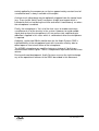
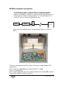
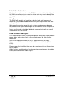
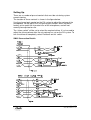
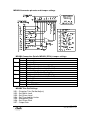
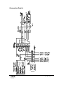
* +
-----
!" #$% & '' ( $) ))
!" #$ % & '' ( , )
+
+ .
+
+ /
Single-Button Microphone Unit (SMU1)
Incorporating Microphone Pre Amplifier (MPAB3)
User Manual V1.3
page 1 of 15
21016 SMU1-MPAB3 V1.3.doc
Revision History
Version
1.0
1.1
1.2
1.3
Modifications
Original issue.
First Revisions
Cable Type Changed
Connection Details Added
Date
19/07/01
26/09/01
21/10/05
16/12/05
© Copyright Audix Systems. 2005
DISCLAIMER
This manual contains information that is correct to the best of Audix Systems
knowledge. It is intended to be a guide and should be used as such. It
should not be considered as a sole source of technical instruction, replacing
good technical judgement, since all possible situations cannot be anticipated.
If there are any doubts as to exact installation, configuration and/or use, call
Audix Systems at +44 (0)1799 540888
ACKNOWLEDGEMENTS
All trademarks are recognised
page 2 of 15
21016 SMU1-MPAB3 V1.3.doc
Models Covered
This user manual covers the following equipment
•
•
SMU1 (570.005.005) Single Button Paging Microphone
MPAB3 (570.005.007) Microphone Pre Amplifier
Technical Support
In the unlikely event of you having problems with your SMU 1 please contact
our Technical Support.
Audix Systems
Station Road
Wenden
Saffron Walden
CB11 4LG
Tel +44 (0)1799 540888
Fax +44 (0)1799 541618
Website www.tycosafetyproducts-europe.com, www.audixsystems.co.uk
page 3 of 15
21016 SMU1-MPAB3 V1.3.doc
Table of contents
Revision History.......................................................................................................2
Models Covered ...........................................................................................3
Technical Support ........................................................................................3
Table of contents..........................................................................................4
Product Description ......................................................................................5
SMU1 Overview ...........................................................................................7
SMU1 Operating instructions........................................................................7
MPAB3 microphone preamplifier..................................................................8
SMU1 Specification ......................................................................................9
MPAB3 Specifications ..................................................................................9
Installation Instructions...............................................................................10
Wiring......................................................................................................10
Fixed Installation Cable types. ................................................................10
Setting Up...................................................................................................11
SMU1 Connection DetailsMPAB3 Connector pin-outs and Jumper
settings ...................................................................................................11
MPAB3 Connector pin-outs and Jumper settings ...................................12
Connection Deatils .....................................................................................13
Safety Considerations. ...............................................................................14
D718 MPAB3 Pre Amplifier Board..............................................................15
page 4 of 15
21016 SMU1-MPAB3 V1.3.doc
Product Description
The SMU1 is desk mounted microphone console for primarily designed for
use with Audix Systems Public Address and Voice Alarm controllers.
Led indicators provide comprehensive status display.
Red LED’s showing when zones are busy, green LED’s show when calls are
successful.
The SMU1 features a good quality dynamic microphone, chosen for its clear
and natural sound.
The MPAB3 is a low noise remote microphone amplifier board with balanced
input and built in AGC/compressor maintain maximum intelligibility. The
nominal compression ratio is 5 to 1, but increases towards the higher level
end of the range.
The underlying AGC operates slowly with an attack time of around 3s ( gain
control is mostly transferred from the compressor) and release time of around
10s, but has a fast recovery (approx. 1s rate ) which operates if the output
level falls below 10 to 15dB of its current nominal value for longer than 1.5s.
The AGC recovery rate of around 10s is re-established when the signal level
recovers to within the 15dB range of the nominal output level.
The compressor effectively operates "over the top" of the AGC to reduce the
dynamic range of the gain adjusted signal. The reason for this approach
(rather than just having a simple compressor is to reduce the amount of
crackle and distortion of the signal to improve overall intelligibility of the
speech signal.
The compressor operates normally with an attack time of around 10ms and a
release time of 200ms which gives good dynamic range control with minimal
attack distortion. To control the initial attack and any subsequent large
excursions of the signal, the attack time speeds to around 1ms for any
instantaneous input increase of greater than about 4dB above the current
output level.
To help prevent the compressor modulating the noise during short pauses in
the input speech signal (i.e. unwanted "breathing") the compressor release
time is increased greatly if the output level falls to below 10 to 15dB of the
current output level. Normal control is re-established when the output level
rises above this level.
The board also incorporates a 20kHz surveillance oscillator which injects tone
directly into the microphone input for use in the rest of the PA system, but
which will also detect (absence of tone) a short or open circuit fault at the
microphone. The 20kHz generator is arranged to inverse-track the gain
page 5 of 15
21016 SMU1-MPAB3 V1.3.doc
control applied by the compressor so that an approximately constant level of
surveillance tone is always available at the output.
A chime circuit (ding-dong) may be optionally triggered from the control input
(e.g. Press to talk switch) and if used gives a logic level output which is
intended to flash an led during the chime and switch it continuously on when
the microphone is enabled.
Finally, the microphone is 'live' all of the time so as to enable continuous
surveillance of all of the circuitry in the system. However, to avoid audible
signal pick-up from the microphone in its non-active state, additional gain
reduction is applied in this state which is switched out when the microphone
is required.
A digitally synthesized 20kHz monitor tone for the Audix Systems FMS is
injected directly at the microphone head, with innovative circuitry able to
detect open or short circuit failure of the microphone.
The MPAB3 microphone pre amplifier features a choice of 2 built in pre
announcement chime signals. There is independent adjustment for the chime
volume.
Due to continued development, Audix Systems reserves the right to change
any of the operational features of the SMU1 described in this document.
page 6 of 15
21016 SMU1-MPAB3 V1.3.doc
SMU1 Overview
The microphone comprises;
• Desk mount microphone unit with PTT (Press To Talk Button)
• Speak indicator (Green)
• Busy indicator (Red)
• Goose neck Microphone
• Microphone pre-amplifier unit in separate junction box (MPAB3)
SMU 1
SMU1 Operating instructions
Operation LIVE broadcast
•
When the SMU is idle the red LED will show if the system is busy.
•
To make an announcement the user is to press and hold the Speak button.
Until this point announcer has had no effect on the PA system.
•
A rapidly flashing green LED by the Speak button, indicates that the preannounce chime is active and the announcer should wait until this green
LED stays solidly on. This is the Speak-now indication.
•
Whilst holding the Speak button, the announcer should then talk steadily
and clearly into the microphone with their mouth about 10 to 20 cm. from
the microphone head.
•
The call ends when the announcer releases the Speak button, thereby
turning off the microphone, indicated by the Green LED’s turning off.
page 7 of 15
21016 SMU1-MPAB3 V1.3.doc
MPAB3 microphone preamplifier
The MPAB3 pre amplifier is used with SMU1 or handheld microphones.
These are the only Audix microphones without an integral pre amp/line
amplifier. The MPAB3 is housed in a metal box and will require fixing near to
the microphone. The box is fitted with glands. It is the responsibility of the
installer to ensure the cables are glanded correctly.
MIC
MPAB
RACK
Terminations
Dimensions of line amplifier boxes are approximately 200mm X 130mm X
50mm
The unit is connected to the PA system via a four pair cable (Belden 8778
equivalent).
Pair 1: The unit is powered from a nominal 24V D.C. supply.
Pair 2: PTT control Out
Pair 3: Audio output from the unit is at balanced line level audio 0dBu nominal.
Pair 4: Busy control in and Live control in
page 8 of 15
21016 SMU1-MPAB3 V1.3.doc
Each pair should be individually screened, with a common overall screen
connected to earth.
SMU1 Specification
Microphone Technology
Frequency Response
Sensitivity
Impedance
Directional Characteristics:
From 200Hz – 2kHz
From 2kHz – 5kHz
Switch (Max DC switching current)
LED current Requirment (24V DC)
Busy Indication
Speak Indication
Cable Length (Filotex)
Dynamic
150Hz – 7kHz (+/- 3dB)
-83.5dB re 1V/uBAR +/- 4dB
200 ohm +/- 15%
Greater than 10dB
Greater Than 8dB
50mA
~10mA
Red LED
Green LED
3 meters
MPAB3 Specifications
Power supply voltage range
Supply current (typical)
15 – 30V DC
55mA @ 24V
Audio output nominal
Audio output max.
Output impedance
Load impedance
Distortion T.H.D.
Signal to Noise ratio
0dBu
+10dBu
< 50 ohms
> 600ohms
< 0.05%
Pre-announcement chimes
2 or 3 tone
Microphone gain trim range
Preset
Surveillance tone Frequency
Surveillance tone Level
Surveillance tone stability
20kHz
Adjustable
o
100ppm/ C
Operating Distance (From Rack), SMU1
Operating Distance(From Rack), SMU1 used with
MPAB3
Operating temperature range
Max Humidity
EMC operating environment
(As defined by EN50081-1, EN50082-1)
Manufactured to Safety Standard
100m
500m
o
0 – 40 C
85% non-condensing
Domestic, Commercial,
Light Industrial.
EN60065:1998
page 9 of 15
21016 SMU1-MPAB3 V1.3.doc
Installation Instructions
Warning: Upon first connection of the SMU1 to a system, the initial setting of
the 20kHz surveillance tone is set at the factory and may need to be adjusted
during system commissioning.
Wiring.
The SMU1 will normally be located on a desk or table, but is permanently
wired into a junction box/wall box/MPAB3 using the single flexible multi core
cable provided.
Wiring from the junction box to the main systems equipment may be made
with different cable types, depending on the environment and the length of the
cable run.
In any case the cable should be individually screened pairs, with an over-all
screen which must be earthed.
Fixed Installation Cable types.
Care should be taken when installing microphone cabling with respect to other
power cables and systems likely to cause interference e.g. Mains cabling,
Motors etc.
In its normal operational mode the unit is supported on a 4 pair cable.
However we would recommend using 6 twisted screen pair cable (Belden
8778).
Depending on the installation there may be a requirement to use fire resistant
or LSF cables.
Audix Systems can offer advice, based on previous experience as to suitable
cable types and maximum cable lengths.
page 10 of 15
21016 SMU1-MPAB3 V1.3.doc
Setting Up.
There are a number of pre-set controls that must be set during system
commissioning.
The location of these controls is shown in the figure below.
Use the channel gain control on the PA system to adjust the volume of the
microphone. Do not adjust the “mic pre-set gain control” which has been
factory set to match the characteristics of the microphone, and will not
normally be adjusted on site.
The “chime switch” will be set to select the required chime. It is also used to
adjust the chime volume after the mic volume has set on the PA system. To
turn the chime off completely select Position 0 on this switch.
SMU1 Connection Details
page 11 of 15
21016 SMU1-MPAB3 V1.3.doc
MPAB3 Connector pin-outs and Jumper settings
MPAB3
Wiring
MPAB3 Connection Details MPAB3 (D718) Jumper settings
Omit
2 tone chime
J1
Fit
3 tone chime
J2
Omit
Enable Chime
Fit
Disable Chime
J3
Omit
Ptt Operation, Active Low (Fit J5)
Fit
Ptt Operation, Active High (Omit J5)
J4
Omit
Normal Operation
Fit
Permanently Enable Pre Amplifier
J5
Omit
Ptt Operation, Active High (Fit J3)
Fit
Ptt Operation, Active Low (Omit J3)
J6
Omit
Power Off
Fit
Power On
J7
Omit
A1 > A1
Fit
A1 > SCREEN
MPAB3 Trim Pot Settings
VR1 – Distortion Trim (Do Not Adjust)
VR2 – Set 20kHz Level
VR3 – Set Chime Level
VR4 – Set Threshold for Limiter
VR5 – Microphone Gain
VR6 – Set Chime Pitch
VR7 – Output Gain
page 12 of 15
21016 SMU1-MPAB3 V1.3.doc
Connection Details
page 13 of 15
21016 SMU1-MPAB3 V1.3.doc
Safety Considerations.
Review the following safety precautions to avoid injury and prevent damage to
the product. The product should only be used as specified.
The SMU1 should be operated from a suitable DC supply of nominally 24V.
Use only the correct power source, which must contain current overload
protection to protect the wiring between the system and the SMU1.
Do not disconnect the cable from the product whilst the Voice Alarm system is
powered.
Do not operate in wet or damp conditions or expose to dripping or splashing.
Do not operate in an Explosive Atmosphere
This product may be incorporated into a Monitored Voice Alarm system. If so,
to tamper with any of the setting of the SMU1 unit may cause a Fault
Condition warning on the Voice Alarm control unit. In these circumstances the
restoration of normal operation of the system may not be possible without
access to the Main Voice Alarm Equipment by qualified personnel.
page 14 of 15
21016 SMU1-MPAB3 V1.3.doc
D718 MPAB3 Pre Amplifier Board
page 15 of 15
21016 SMU1-MPAB3 V1.3.doc