1
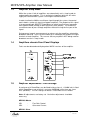
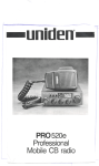
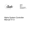
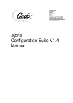
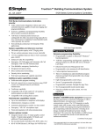
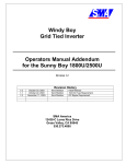
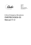
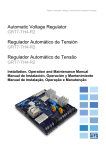
MVPA/VPA Amplifier User Manual
Audix Systems,
Station Road,
Wenden,
Saffron Walden,
Essex,
CB11 4LG.
Telephone: +44(0)1799 540888
Facsimile: +44(0)1799 541618
www.tycosafetyproducts-europe.com
www.audixsystems.co.uk
MVPA / VPA Amplifier
Manual V1.1
Page 1 of 11
21015 V1.1
MVPA/VPA Amplifier User Manual
Revision History
Versio Modifications
1.0
1.1
Date
Initial Draft
Revised
09/07/2001
18/06/2002
© Copyright Audix Systems. 2005
DISCLAIMER
This manual contains information that is correct to the best of Audix Systems knowledge. It
is intended to be a guide and should be used as such. It should not be considered as a sole
source of technical instruction, replacing good technical judgement, since all possible
situations cannot be anticipated. If there are any doubts as to exact installation,
configuration and/or use, call Audix Systems at +44 (0)1799 540888
ACKNOWLEDGEMENTS
All trademarks are recognised
Technical Support
In the unlikely event of you having problems with your Amplifier please contact our
Customer Services Department.
Audix Systems
Station Road
Wenden
Saffron Walden
CB11 4LG
Tel 01799 540888
Fax 01799 541618
Page 1 of 11
21015 V1.1
MVPA/VPA Amplifier User Manual
CONTENTS
REVISION HISTORY.................................................................................................................... 1
TECHNICAL SUPPORT ............................................................................................................... 1
1.
SPECIFICATION............................................................................................ 3
1.1
1.2
1.3
1.4
1.5
1.6
2.
SAFETY CONSIDERATIONS................................................................................... 9
2.1
2.2
2.3
2.4
3
AMPLIFIER MODEL RANGE .............................................................. 4
AMPLIFIER INTRODUCTION .............................................................. 4
AMPLIFIER SLEEP MODE ................................................................. 5
AMPLIFIERS CHASSIS FRONT PANEL DISPLAYS .................... 5
AMPLIFIER ADJUSTMENTS / LINK SETTINGS ........................... 5
AMPLIFIER PANEL ARRANGEMENT (MVPA1202)................. 8
Safety Considerations for System Maintenance.................................... 9
Electrical Hazards ..................................................................................... 9
Heat Hazards. .......................................................................................... 10
Weight Hazards. ...................................................................................... 10
MAINTENANCE ...................................................................................................... 10
Page 2 of 11
21015 V1.1
MVPA/VPA Amplifier User Manual
1.
Specification
Power Requirements (AC / DC)
Amplifier chassis voltage requirements
AC inrush current
(Chassis fitted with 4 x 60 Watt
PowerBlocs)
1 x 60 Watt RMS PowerBloc
2 x 60 Watt RMS PowerBloc
3 x 60 Watt RMS PowerBloc
4 x 60 Watt RMS PowerBloc
Power Factor
Heat Dissipation (Watts)
240 Watt Amplifier (Full Power)
240 Watt Amplifier (Half Power)
th
240 Watt Amplifier (1/8 Power)
Automatic thermal shutdown
Audio / Electrical Characteristics
Input Impedance
Input Sensitivity
Power Bandwidth (-3dB)
Distortion (THD)
Noise
Fault Monitoring
Built in monitoring circuitry
(Fitted in MVPA models only)
Short circuit protection
Mechanical
Dimensions (HxWxD)
Audio connections
Mains connections
DC supply connections
Amplifier Finish
Reliability / Maintainability
MTBF (hours)
MTTR (i.e. fit replacement amp bloc)
Environment
Operating temperature range ( C)
Relative Humidity
230 volts AC 50/60Hz with automatic
reversion to 24VDC during AC failure
10A maximum for less than 1 second, non
repetitive (typically <7.5A)
160VAC / 6.5ADC Max
320VAC / 13ADC Max
480VAC / 19.5ADC Max
640VAC / 26ADC Max
0.85 at maximum power
325 Watts
300 Watts
175 Watts
Gain reduction while heatsink exceeds
85 C
10K ohms nominal, electronically balanced
0dBu (775mV) for rated power
100Hz – 20Khz
Less than 1% at rated power, typically less
than 0.08% at 1Khz.
-80dB max
Detection and display of individual
PowerBloc Fail, Mains Fail, Battery Fail
and Charger Fail. With general fault output
to Monitoring System (FMS).
Indefinite operation into short cct load
133 (3U) x 483 x 310 (rack mount
19”frame)
Plug-in connectors with screw terminals
I.E.C. mains connector
4-pin multiway connector
Black
90,000 hours
15 minutes
-5 C to 40 C
0 – 95%
Page 3 of 11
21015 V1.1
MVPA/VPA Amplifier User Manual
1.1
Amplifier Model Range
Audix
Systems
Model No.
Output
Channel
s
Weight
MVPA601
MVPA602
MVPA603
MVPA604
MVPA1201
1 x 60W
2 x 60W
3 x 60W
4 x 60W
1x
120W
2x
120W
1x
120W
1 x 60W
1x
120W
2 x 60W
1x
180W
1x
180W
1 x 60W
1x
240W
MVPA1202
MVPA1260
MVPA1262
MVPA1801
MVPA1860
MVPA2401
1.2
230AC
(mA)
Quiescen
t
57
64
71
78
60
24VDC
(A)
Max.
230VAC
(A)
Max.
10Kg
12Kg
14Kg
16Kg
12Kg
24VDC
(mA)
Quiescen
t
130
200
270
340
145
6.5
13
20
26
13
0.7
1.4
2
2.78
1.4
16Kg
230
70
26
2.78
14Kg
215
67
20
2
16Kg
285
74
26
2.78
14Kg
160
63
20
2
16Kg
230
70
26
2.78
16Kg
175
66
26
2.78
Amplifier Introduction
Audix Systems 60 watt 'PowerBloc' amplifier modules are used individually or
combined to provide 100 Volt line outputs of 60, 120, 180 or 240 Watts R.M.S. A
rack mounting chassis/power supply occupying 3U of space holds up to four
PowerBloc modules which may be arranged as four totally independent 60 watt
amplifiers or in any of ten other output configurations (see paragraph 1.2
‘Amplifier model range’ for details).
Using proven MOSFET circuit techniques results in an efficient and extremely
reliable power amplifier. The amplifiers are protected from short circuit speaker
lines by current limiting on the output stage. The amplifiers are protected from
persistently being over-driven by a thermal cut-out which is triggered at 85°C
decreasing the amplifier input drive to reduce the output stage power dissipation.
Modules operating in parallel share a single input/driver stage. Input level
controls may be fitted to all combinations of PowerBlocs as appropriate.
The output power of existing units can be increased at any time by the addition of
more PowerBloc output modules (subject to available space in the mainframe).
Page 4 of 11
21015 V1.1
MVPA/VPA Amplifier User Manual
1.3
Amplifier Sleep Mode
While the system is idle all amplifiers are automatically set in ‘sleep’ mode to
reduce power consumption. This is particularly important while the AC mains
supply has failed and the system is running on internal batteries.
In order to allow the 20Khz surveillance signal through the system, the control
matrix feeds a ‘wake-up’ signal to all power amplifiers. The purpose of this signal
is to command Audix MOSFET PowerBlocs to switch from their very low power
consumption mode (asleep) to their quiescent state (awake). This allows the
surveillance tone to pass through amplifiers without missing the first part of the
signal.
During normal speech announcements or alarms only the amplifiers selected for
broadcast wake-up. In this case the wake-up is initiated by the audio at the input
terminals of each amplifier. This ensures that any amplifiers NOT being used for
broadcast remain in ‘sleep’ mode.
1.4
Amplifiers chassis Front Panel Displays
Faults can be detected and displayed on ‘MVPA’ versions of the amplifier.
1.5
Amplifier Adjustments / Link Settings
A maximum of 4 PowerBlocs can be fitted inside a chassis. A 240W unit is fitted
with 4 PowerBlocs, one of which is a master (MPB260), while three are slave
units (MPB261). The link settings on Master / Slave Blocs are as follows:
Note: All adjustments are factory set. No further adjustments should be
necessary.
MPB160 Master
VR1
VR2
-
Fine Gain Control
Quiescent Current
MPB161 Slave
Page 5 of 11
21015 V1.1
MVPA/VPA Amplifier User Manual
VR1
VR2
-
Not fitted
Quiescent Current
Front panel mounted lockable gain adjustment controls can be fitted (optional) to
each Master PowerBloc. This allows user adjustment of audio levels, during
system commissioning, which can be locked once set.
Page 6 of 11
21015 V1.1
MVPA/VPA Amplifier User Manual
Link Settings for MPB260 & 261
J1
wake-
-
Master / Slave. This 2 way jumper allows the Master Bloc to
J2
Lk1
-
up other associated slave Blocs in the same chassis.
When fitted the audio input causes the amplifier to wake-up
When not fitted the amplifier is permanently awake
Monitor Board D678 Link Settings
intervals
J1
-
If fitted the sample rate changes from 30 to 4 seconds
(This link is temporarily fitted during PCB testing. All PCB’s
are
J2
J3
J4
J5
CHG
BATT
-
factory set at 30 seconds)
Jumper not fitted if amplifier fitted in slot position 1
Jumper not fitted if amplifier fitted in slot position 2
Jumper not fitted if amplifier fitted in slot position 3
Jumper not fitted if amplifier fitted in slot position 4
Fitted if system includes a battery charger
Fitted if system includes back-up batteries
Important Note:
The current amplifier PowerBloc range is MPB260 (Master) and MPB261
(Slave). Older versions include 160, 161, 60 and 61. When fitting
PowerBlocs into existing power / frames ensure that different versions are
NOT mixed. I.E. 260 units should only be mixed with 261 units and 160
units should only be mixed with 161 units etc.
Page 7 of 11
21015 V1.1
MVPA/VPA Amplifier User Manual
1.6
Amplifier Panel Arrangement (MVPA1202)
AUDIX SYSTEMS
Ω
Ω
Page 8 of 11
21015 V1.1
MVPA/VPA Amplifier User Manual
2.
SAFETY CONSIDERATIONS
The electrical installation of which the amplifier PowerBloc is part must
incorporate an all-pole mains isolating switch, with contact separation of at least
3mm.
The mains power supply cord to the amplifier unit must have conductor area at
least 1mm . The power cord must be BASEC or HAR approved with connectors
complying with EN60320 and must provide a safety earth.
Audix systems standby battery supply units (Models SBS241, SBS242, or
SBS481) all include a separate fuse on each 24V dc output. The fuse rating on
the feed to a 240 Watt amplifier should be 25A anti-surge (T25AH)
Where a 24V DC standby supply is connected, the DC feed to the amplifier
should be fused at source with a supply fuse rating of 25A anti-surge (T25AH).
The amplifier should not be exposed to dripping or splashing and any liquids.
2.1
Safety Considerations for System Maintenance
Only a qualified and trained electronics engineer should be permitted to
make any type of adjustment or repair to the Public Address or Voice
Alarm System.
The following safety factors should be considered before attempting to maintain
or repair an amplifier
• Electrical
• Heat
• Weight
2.2
Electrical Hazards
High Voltages exist within this apparatus:
• 230 volt mains
• 100V line
An power / frame primary supply is 230v AC 50-60Hz. This is connected by
means of an IEC fused inlet. This equipment does not include a mains isolation
switch therefore the:
Mains must be disconnected from the apparatus before any part of the
casing is removed.
Insulated shrouds protect the mains supply within the apparatus. No part of the
mains supply can be easily touched unless these internal covers are removed.
Battery Backup
Where the amplifier has a secondary supply i.e. 24Volt Battery backup:
Page 9 of 11
21015 V1.1
MVPA/VPA Amplifier User Manual
The battery supply must be also be disconnected before any part of the
casing is removed.
2.3
Heat Hazards.
There is a potential temperature hazard around the rear an amplifier frame. The
MVPA power amplifier heat sinks may become Very Hot. This is generally when
an
alarm has been broadcast for a long period of time. Heating may also occur if
the
amplifier power block is in a fault condition.
2.4
Weight Hazards.
Warning:- Amplifier frames are heavy!
If an amplifier frame is to be moved the appropriate lifting code of practice
should be followed.
Approximate frame weight is 14 – 16Kg’s (Depending on particular model)
3
Maintenance
Although MVPA amplifiers require little or no maintenance the Public Address or
Voice Alarm system to which it is installed may require regular scheduled
maintenance.
For BS5839 compliant Voice Alarm systems please refer to BS5839 Part 1 (Code
of practice for system design, installation and servicing) for recommend
maintenance levels.
It is recommended that all members of staff should be urged to report problems
with the PublicAddress or Voice Alarm system (i.e. distortion, speakers not
operating, poor coverage) to the department responsible for the maintenance of
such equipment.
For assistance, please contact our Customer Services Department to obtain
advice on planned maintenance and Service Contracts
Page 10 of 11
21015 V1.1