1
PT110-IP
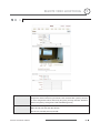
Indoor Vandal Resistant 10x IP PTZ Dome
User Manual
NY: 55 Mall Drive • Commack, NY 11725 (800) 422-6707
CA: 20521 Earl Street • Torrance, CA 90503 (877) 407-9555
www.computarganz.com
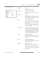
Warning: Do not open the case and disassemble the product. No user serviceable parts included.
Please contact authorized service agent.
This
lightning
flash with
arrowhead
is intended
to alert
the⋆㡴
user 㤸㚉㢨
to the
㢨 䖐㐐⏈
㇠⣀㜄᷀
㤸ὤ㤵
㻝ᷝ㡰⦐symbol
㢬䚐 㠸䜌㉥㢨
㻝⺸䢼
㢼⏈
presence of un-insulated "dangerous voltage" within the product's enclosure that
㥐䖼 ⇨⺴㜄㉐ ⇌䇴⇌᷀ ╜㡰⦐㒜 㢨⤠䚐 㤼㜤╌㫴 㙾㡴 ⋆㡴 㤸㚉㡰⦐⺴䉤㢌
may be of sufficient magnitude to constitute a risk of electric shock to persons.
㠸䜌㉥㡸 ㇠㟝㣄㜄᷀ ᷱḔ䚌⏈ 䖐㐐㢹⏼␘.
This exclamation point symbol is intended to alert the user to the presence of
important
and maintenance
(servicing)
instructions
in the literature
㢨 䖐㐐⏈ operating
㥐䖼㡸 ┍㣅㐐䇘ᶤ⇌
㥉⽸(⸨㍌)⪰
䚜㜄
㢼㛨㉐ 㩅㟈䚐
⇨㟝㢸㡸
accompanying
appliance.
㇠㟝㣄㜄᷀ 㨰㫴the㐐䇘⏈
䖐㐐㢹⏼␘.
G
G
G
G
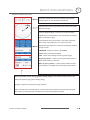
NOTICE
G
Important Safeguard
1.
Read Instructions
Read all of the safety and operating instructions before using the product.
2.
Retain Instructions
Save these instructions for future reference.
3.
Attachments / Accessories
Do not use attachments or accessories unless recommended by the appliance manufacturer as they may
cause hazards, damage product and void warranty.
4.
Water and Moisture
Do not use this product near water or moisture.
5.
Installation
Do not place or mount this product in or on an unstable or improperly supported location. Improperly
installed product may fall, causing serious injury to a child or adult, and damage to the product. Use only
with a mounting device recommended by the manufacturer, or sold with the product. To insure proper
mounting, follow the manufacturer's instructions and use only mounting accessories recommended by
manufacturer.
6.
Power source
This product should be operated only from the type of power source indicated on the marking label.
Precautions
Operating
z
Before using, make sure power supply and others are properly connected.
z
While operating, if any abnormal condition or malfunction is observed, stop using the camera
immediately and then contact your local dealer.
Handling
z
Do not disassemble or tamper with parts inside the camera.
z
Do not drop or subject the camera to shock and vibration as this can damage camera.
z
Care must be taken when you clean the clear dome cover. Scratches and dust will ruin the image
quality of your camera.
Installation and Storage
z
Do not install the camera in areas of extreme temperatures in excess of the allowable range.
z
Avoid installing in humid or dusty places.
z
Avoid installing in places where radiation is present.
z
Avoid installing in places where there are strong magnetic fields and electric signals.
z
Avoid installing in places where the camera would be subject to strong vibrations.
z
Never expose the camera to rain and water.
GPT110-IP Instruction Manual
3 G
G
G
G
G
Content
¢ Introduction
Features
7
Product & Accessories
9
Parts Name & Functions
10
£ Installation
DIP Switch Setup
13
Direct Installation on the Ceiling
16
Installation using Pendant Mount Bracket
17
Installation using Wall Mount Bracket
18
Installation using Flush Mount Bracket
19
Cabling
20
¤ Operation
GPT110-IP Instruction Manual
Check Points before Operation
23
Preset and Pattern Function Pre-Check
23
Starting OSD Menu
24
Reserved Preset
24
Preset
25
Swing
25
Pattern
26
Group
27
Other Functions
28
OSD Display of Main Screen
29
4 G
G
G
G
G
Content
¥ How to use OSD Menu
General Rules of Key Operation for Menu
31
Main Menu
31
Display Setup
32
Privacy Zone Mask Setup
33
Camera Setup
34
Motion Setup
36
Preset Setup
38
Swing Setup
39
Pattern Setup
40
Group Setup
41
System Initialize
43
¦ Remote Video Monitoring
Remote Video Monitoring
45
Initialize IP address
47
IP finder in remote client
48
IP Finder Configuration
49
Use Internet Explorer
50
System
51
Video
52
Audio
54
Network
55
Serial
57
Event
58
Preset
59
User
60
§ Specifications
GPT110-IP Instruction Manual
Specifications
63
Dimension
65
5 G
G
G
G
G
CHAPTER
1
Chapter 1.
INTRODUCTION
GPT110-IP Instruction Manual
6 G
G
G
G
G
INTRODUCTION 1
Features
Camera Specifications
z
CCD Sensor
z
Zoom Magnification : u 10 Optical Zoom, u 10 Digital Zoom (Max u 100 Zoom)
z
Day & Night Function
z
Various Focus Mode : Auto-Focus / Manual Focus / Semi-Auto Focus.
z
Independent & Simultaneous Camera Characteristic Setup in Preset operation
: 1/4" Interline Transfer CCD
Advanced Pan/Tilt Functions
z
Max. 360q/sec high speed Pan/Tilt Motion
z
Using Vector Drive Technology, Pan/Tilt motions are accomplished with the shortest path. As a
result, time to target view is reduced dramatically and the video stream transfers are natural to
watch.
z
For jog operation using a controller, an ultra slow speed of 0.05q/sec can be reached, making it very
easy to relocate camera to the desired target view. Additionally, it is easy to move the camera to a
desired position with zoom-proportional pan/tilt movement.
.
Preset, Pattern, Swing, Group, Privacy Mask and More…
z
Max. 127 Presets are assignable and characteristics of each preset can be set up independently,
such as White Balance, Auto Exposure, Label and so on.
z
Max. 8 set of Swing actions can be stored. This enables camera to move automatically between two
preset positions at a designated speed.
z
Max. 4 Patterns can be recorded and played back. This enables camera to automatically follow any
trajectory preset by joystick as closely as possible.
z
Max. 8 set of Group action can be stored. This enables camera to move automatically with a
combination of Preset or Pattern or Swing. A Group is composed of max. 20 entities of Preset/
Pattern/Swings.
z
Privacy Masks are assignable, so as not to intrude on other’s privacy. (4 Privacy Zones)
PTZ (Pan/Tilt/Zoom) Control
z
With RS-485 communication, max. of 255 cameras can be controlled at the same time.
z
Pelco-D or Pelco-P protocol can be selected as a control protocol in the current firmware version.
GPT110-IP Instruction Manual
7 G
G
G
G
G
INTRODUCTION
1
OSD (On Screen Display) Menu
z
OSD menu is provided to display the status of camera and to configure the functions interactively.
z
The information such as Camera ID, Pan/Tilt Angle, Alarm Input and Preset can be displayed on
screen.
Alarm I/O Functions(Analog Only)
z
z
4 alarm sensor Inputs are available.
To completely eliminate external electric noise and shock, alarm sensor Input is decoupled from
photo coupler.
z
If an external sensor is activated, camera can be set to move to the corresponding Preset position.
Reserved Presets for Special Purpose
z
Most camera characteristics can be set up easily and directly with reserved preset, without
entering the OSD menu. For more information, refer to “Reserved Preset” in this manual.
Audio
z
Various Transmission Mode : Unidirectional Mode (IP-server to Client PC / Client PC or Decoder to
IP-server), Bi-directional Mode
Video
z
High-Quality Compression Algorithm, H.264
z
Compression into Various Resolution : CIF, Half-D1, D1
z
Wide Range of Video Transmission Rate : 32kbps ~ 4Mbps
z
Various Transmission Mode : CBR, VBR
z
Motion Detection
Network
z
Static IP and Dynamic IP(DHCP, PPPoE) Support
z
One to One Connection and One to Multiple Connection
z
Multi-Casting
z
Automatic Transmission Rate Control by Network Condition
User Interface
z
System Status Display with OSD(On Screen Display)
z
System Configuration via Internet Explorer
Reliability
z
Reliable Embedded System
z
System Recovery with Dual Watch-Dog Function
GPT110-IP Instruction Manual
8 G
G
G
G
G
1
INTRODUCTION
Product & Accessories
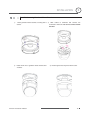
Product & Accessories
z Main Body
z Surface Mount Bracket
z Screws & Terminal Block
z Wrench
z Audio Cable & Video Cable
z Lan Cable
Options
GGGGGG
GGGGGGGG
GGGGGG
z Flush Mount Bracket
GPT110-IP Instruction Manual
GGGGGG
z Pendant Mount Bracket
G
z Wall Mount Bracket
9 G
G
G
G
G
1
INTRODUCTION
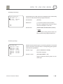
Parts Name & Functions
G
Surface Mount Bracket
Cabling Terminal Block
G
G
G
Audio
Mounting Hole
Safety Retention Spring
Main Body
Lock-up Screw
RJ-45
DIP Switch
Dome Cover
Main Unit / Surface Mount Bracket
z Dome Cover
Back of Main Unit
Do not remove protective vinyl from dome cover before finishing all
installation processes to protect dome cover from scratches or dust.
z Surface Mount Bracket
Used to install the camera directly on the ceiling. Separate the cover
first and then attach it directly to ceiling. Camera must be assembled
at the last stage.
Do not use this bracket when installing camera on the wall with wall
mount bracket or on the ceiling with pendant mount bracket.
z Lockup Screw
Fixes main unit to surface mount bracket.
z Cabling Terminal Block
During installation, Power, Video, Communication, Alarm Input cables
are connected on to this cabling terminal block.
z Fall-Proof Spring
GPT110-IP Instruction Manual
Pull out from Surface Mount Bracket and connect to Main Body hook.
10 G
G
G
G
G
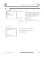
1
GND
IN
POWER
LED
OUT
INTRODUCTION
RESET
z Reset Button
Reboot the network function when it is NOT working properly.
z Power LED
Illuminates in bright red when the power is supplied to the unit.
z Audio Connection
Connect to a speaker, MIC, and Ground Wire with an appropriate wire.
GPT110-IP Instruction Manual
11 G
G
G
G
G
CHAPTER
2
Chapter 2.
INSTALLATION
GPT110-IP Instruction Manual
12 G
G
G
G
G
INSTALLATION
2
DIP Switch Setup
Before you install the camera, you should set the DIP switches to configure the camera ID and communication
protocol.
Camera ID Setup
z
ON
ON
z
1
ID number of camera is set using a binary number. Example is
shown bellow.
2
3
4
5
6
7
8
The range of ID is 1~255. Do not use 0 as camera ID. Factory
default of Camera ID is 1.
z
If you want to control a certain camera, you must match the camera
ID with Cam ID setting of DVR or Controller.
Pin
1
2
3
4
5
6
7
8
Pin
1
2
3
4
5
6
7
8
ID
1
2
4
8
16
32
64
128
ID
1
2
4
8
16
32
64
128
1
on
off
off
off
off
off
off
off
11
on
on
off
on
off
off
off
off
2
off
on
off
off
off
off
off
off
12
off
off
on
on
off
off
off
off
3
on
on
off
off
off
off
off
off
13
on
off
on
on
off
off
off
off
4
off
off
on
off
off
off
off
off
14
off
on
on
on
off
off
off
off
5
on
off
on
off
off
off
off
off
15
on
on
on
on
off
off
off
Off
6
off
on
on
off
off
off
off
off
16
off
off
off
off
on
off
off
off
7
on
on
on
off
off
off
off
off
17
on
off
off
off
on
off
off
off
8
off
off
off
on
off
off
off
off
18
off
on
off
off
on
off
off
off
9
on
off
off
on
off
off
off
off
19
on
on
off
Off
on
off
off
off
10
off
on
off
on
off
off
off
off
20
off
off
on
off
on
off
off
off
GPT110-IP Instruction Manual
13 G
G
G
G
G
2
INSTALLATION
Pin
1
2
3
4
5
6
7
8
Pin
1
2
3
4
5
6
7
8
ID
1
2
4
8
16
32
64
128
ID
1
2
4
8
16
32
64
128
21
on
off
on
off
on
off
off
off
31
on
on
on
on
on
off
off
off
22
off
on
on
off
on
off
off
off
32
off
off
off
off
off
on
off
off
23
on
on
on
off
on
off
off
off
33
on
off
off
off
off
on
off
off
24
off
off
off
on
on
off
off
off
34
off
on
off
off
off
on
off
off
25
on
off
off
on
on
off
off
off
35
on
on
off
off
off
on
off
Off
26
off
on
off
on
on
off
off
off
36
off
off
on
off
Off
on
off
off
27
on
on
off
on
on
off
off
off
37
on
off
on
off
Off
on
off
off
28
off
off
on
on
on
off
off
off
38
off
on
on
off
Off
on
off
off
29
on
off
on
on
on
off
off
off
39
on
on
on
off
Off
on
off
off
30
off
on
on
on
on
off
off
off
40
off
off
off
on
Off
on
off
off
Communication Protocol Setup
z
ON
Select the appropriate Protocol with DIP switch combination.
ON
Switch State
1
2
3
4
z
P0
(Pin 1)
P1
(Pin 2)
Protocol
OFF
OFF
PELCO-D, 2400 bps
ON
OFF
PELCO-D, 9600 bps
OFF
ON
PELCO-P, 4800 bps
ON
ON
PELCO-P, 9600 bps
If you want to control using DVR or P/T controller, their protocol must
be identical to camera. Otherwise, you can not control the camera.
z
If you changed camera protocol by changing DIP S/W, the change
will be effective after you reboot the camera.
z
Factory default of protocol is “Pelco-D, 2400 bps”.
z
Pin 3 is only for supplier, DO NOT CHANGE THESE ITS ORIGINAL
Reserved for Supplier
ON
ON
U
STATE. If you change one of these, proper operation cannot be
U
achieved.
1
2
3
4
~ Pin 3
PAL / NTSC system selection of Camera. DO NOT
U
CHANGE THIS PIN.
U
GPT110-IP Instruction Manual
14 G
G
G
G
G
INSTALLATION
2
Terminal Resistor Setup
ON
Terminal resistor is used if your system meets one of following two
ON
conditional cases.
1
2
3
4
z
Case1: Control cable between camera and controller is
relatively long (1:1 connection)
If communication cable is very long, the electrical signal will bind in
the terminal point. This reflected signal causes signal distortion,
resulting in a degradation of camera function. In this case, the
terminal resistor of both sides (i.e. camera and controller) must be
set to the ‘ON’ state.
z
Case2: Multiple cameras are controlled at the same time
Due to similar reasons stated in case 1, the terminal resisters of the
controller and the last camera must be set to ‘ON’ state.
The
camera with the longest cable length is determined to be the ‘last’
camera. Do not turn on the terminal resistor of all cameras.
GPT110-IP Instruction Manual
15 G
G
G
G
G
INSTALLATION
2
Direct Installation on the Ceiling
ྙ
To pass cables to upside of ceiling, please
ྚ
make a 2~2.5 inch (50~60mm) hole on the
Fasten surface mount bracket to ceiling with 4
screws.
ceiling panel.
ྛ Wire cables to terminal block and connect the
terminal blocks to main unit.
ྜ
Fasten main unit to surface mount bracket with
4 lock-up screws.
ྜྷٻRemove protective vinyl from dome coverٻډ
G
G
G
G
GPT110-IP Instruction Manual
16 G
G
G
G
G
INSTALLATION
2
Installation using Pendant Mount Bracket
ྙ
Fasten pendant mount bracket to ceiling with 3
screws.
ྚ Wire cables to terminals and connect the
terminals to main unit. Do not use surface mount
bracket!
G
G
G
ྛG Fasten main unit to pendant mount bracket with
ྜٻRemove protective vinyl from dome coverٻډ
4 screws.
GPT110-IP Instruction Manual
17 G
G
G
G
G
INSTALLATION
2
Installation using Wall Mount Bracket
ྙ
Fasten wall mount bracket to ceiling with 3
screws.
ྚ Wire cables to terminals and connect the
terminals to main unit. Do not use surface
mount bracket!
ྛ
Fasten main unit to wall mount bracket with 4
ྜٻRemove protective vinyl from dome coverٻډ
screws.
G
GPT110-IP Instruction Manual
18 G
G
G
G
G
2
INSTALLATION
Installation using Flush Mount Bracket
ྙ
Cut 3 holes in ceiling
ྚG Align main body bracket with flush mount
bracket. Fasten with screws.
.
ྛG Connect fall-proof spring to main body
hook. Assemble and fasten with screws.
ྜྷG Secure flush mount bracket to the ceiling
with screws through the 3 holes on the
ྜG Put main body and bracket assembly into
main hole.
ྞG Cover assembly with bracket
cover and turn it clockwise.
bracket.
GPT110-IP Instruction Manual
19 G
G
G
G
G
INSTALLATION
2
Cabling
Power
PWR(+)
PWR(-)
NC
RS-485(+)
RS-485(-)
VIDEO(+)
VIDEO(-)
Controller/ DVR
IrDA
Sensor
IN COM+
IN1
IN2
IN3
IN4
Door
Switch
BNC
Sensor
Moinitor
Cabling Terminal Block
INTERNET
LAN CABLE
BROWSER
MIC SPEAKER
AUDIO
CABLE
RJ-45
AUDIO
Power Connection
z
Please check the voltage and current capacity of rated power carefully. Rated power is indicated on the
back of main unit.
Rated Power
Input Voltage Range
Current Consumption
DC 12V
DC 11V ~ 18V
1.3 A
RS-485 Communication
z
For PTZ control, connect this line to keyboard and DVR. To control multiple cameras at the same time,
RS-485 communication lines to cameras are connected in parallel as shown below.
GPT110-IP Instruction Manual
20 G
G
G
G
G
Video Connection
z
2
INSTALLATION
INSTALLATION
Connect with BNC coaxial cable.
Alarm Input Connection
z
Sensor Input
Internal
SENSOR IN1
SENSOR COM
(GND)
SENSOR IN2
SENSOR COM
(GND)
SENSOR IN3
SENSOR COM
(GND)
SENSOR IN4
SENSOR COM
(GND)
Before connecting sensors, check the sensor driver voltage and output signal type. Since sensor output
signal types are divided into Open Collector and Voltage Output types in general, the cabling must be
installed properly depending on the signal type.
Signal
Description
COM (GND)
Connect SENSOR COMs to this port(GND) as shown in the circuit above
IN1, IN2, IN3, IN4
Connect output of sensors for each port as shown in the circuit above.
If you want to use Alarm Input, the type of sensor must be selected in OSD menu. The sensor types are
Normal Open and Normal Close. If the sensor type is not selected properly, alarm activation will occur
opposite of what is desired.
~ Normal Open
Output Voltage is high state when sensor is activated
~ Normal Close
Output Voltage is high state when sensor is not activated
GPT110-IP Instruction Manual
21 G
G
G
G
G
CHAPTER
3
Chapter 3.
OPERATION
GPT110-IP Instruction Manual
22 G
G
G
G
G
OPERATION
3
Check Points before Operation
z
Before power is applied, please check the cables carefully.
z
The camera ID of the controller must be identical to that of the target camera. The camera ID can be checked
by reading DIP switch of the camera.
z
If your controller supports multi-protocols, the protocol must be changed to match to that of the camera.
z
If you changed camera protocol by changing DIP switch, the change will be effective after you reboot the
camera.
z
Since the operation method can be different for each controller available, refer to the manual for your
controller if camera can not be controlled properly. The operation of this manual is based on the standard
Pelco® Controller.
Preset and Pattern Function Pre-Check
z
Check controller or DVR preset and pattern function operation in advance to take advantage of full camera
functions when using controller or DVR.
z
Refer to the following table when using standard Pelco® protocol controller.
< Go Preset >
z
Input [Preset Number] and press [Preset] button.
< Set Preset >
Input [Preset Number] and press [Preset] button for more than 2 seconds.
< Run Pattern >
Input [Pattern Number] and press [Pattern] button.
< Set Pattern >
Input [Pattern Number] and press [Pattern] button for more than 2 seconds.
If controller or DVR has no pattern button or function, use shortcut keys with preset numbers. For more
information, refer to “Reserved Preset” in this manual.
GPT110-IP Instruction Manual
23 G
G
G
G
G
OPERATION
3
Starting OSD Menu
z Function
Using the OSD menu, Preset, Pattern, Swing, Group and Alarm Input function can be
configured for each application
z Enter Menu
<Go Preset> [95]
Reserved Preset
z Description
z Function
GPT110-IP Instruction Manual
Some Preset numbers are reserved to special functions.
Go Preset [95]
: Enters into OSD menu
Go Preset [131~134]
: Runs Pattern Function 1 ~ 4
Go Preset [141~148]
: Runs Swing Function 1 ~ 8
Go Preset [151~158]
: Runs Group Function 1 ~ 8
Go Preset [170]
: Sets Camera BLC Mode to OFF
Go Preset [171]
: Sets Camera BLC Mode to ON
Go Preset [174]
: Sets Camera Focus Mode to AUTO
Go Preset [175]
: Sets Camera Focus Mode to Manual
Go Preset [176]
: Sets Camera Focus Mode to SEMI-AUTO
Go Preset [177]
: Sets Day & Night Mode to AUTO
Go Preset [178]
: Sets Day & Night Mode to NIGHT
Go Preset [179]
: Sets Day & Night Mode to DAY
Go Preset [190]
: Sets OSD Display Mode to AUTO (Except Privacy Mask)
Go Preset [191]
: Sets OSD Display Mode to OFF (Except Privacy Mask)
Go Preset [192]
: Setting OSD Display Mode to ON (Except Privacy Mask)
Go Preset [193]
: Sets all Privacy Mask Display to OFF
Go Preset [194]
: Sets all Privacy Mask Display to ON
24 G
G
G
G
G
3
OPERATION
Preset
z Function
Max. 127 positions can be stored as Preset position. The Preset number can be
assigned from 1 to 128, but 95 is reserved for starting OSD menu.
Camera characteristics (i.e. White Balance, Auto Exposure) can be set up
independently for each preset. Label should be blank and "Camera Adjust" should be
set to "GLOBAL" as default. All characteristics can be set up in OSD menu.
z Set Preset
<Set Preset> [1~128]
z Run Preset
<Go Preset> [1~128]
z Delete Preset
To delete Preset, use OSD menu.
Swing
z Function
By using Swing function, you can make camera to move between 2 Preset positions
repeatedly. When swing function runs, camera moves from the preset assigned as the
1st point to the preset assigned as the 2nd point in CW(Clockwise) direction. Then
camera moves from the preset assigned as the 2nd point to the preset assigned as the
1st point in CCW(Counterclockwise) direction.
If the preset assigned as the 1st point is the same as the preset assigned as the 2nd
point, the camera will turn 360q in a CW (Clockwise) direction, then 360q in a CCW
(Counterclockwise) direction.
Speed can be set up from 1q/sec to 180q/sec.
z Set Swing
To set Swing, use OSD menu.
z Run Swing
Method 1) <Run Pattern> [Swing NO.+10]
ex) Run Swing 3 : <Run Pattern> [13]
Method 2) <Go Preset> [Swing NO.+140]
ex) Run Swing 3 : <Go Preset> [143]
z Delete Swing
GPT110-IP Instruction Manual
To delete Swing, use OSD menu.
25 G
G
G
G
G
3
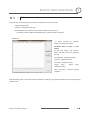
OPERATION
Pattern
z Function
Pattern Function allows the camera to memorize a path (often a curved path) created
by controller joystick for an assigned time. The camera will then retrace the path
exactly as memorized.
4 Patterns are available and Maximum 1200 communication commands can be stored
in a pattern.
z Set Pattern
Patterns can be created by one of following two methods.
Method 1) <Set Pattern> [Pattern NO.]
{
Pattern editing screen is displayed as bellow.
EDIT PATTERN 1
[NEAR:SAVE
/FAR:DELETE]
0/0/x1/N
{
Movement by Joystick and preset movement can be memorized in a pattern.
{
The remaining memory size is displayed in progress bar.
{
To save the recording, press NEAR key and to cancel, press FAR key.
Method 2) OSD Using OSD Menu: See the section “How to use OSD Menu”.
z Run Pattern
z Delete Pattern
GPT110-IP Instruction Manual
Method 1) <Run Pattern> [Pattern NO.]
ex) Run Pattern 2 : <Run Pattern> [2]
Method 2) <Go Preset> [Pattern NO.+130]
ex) Run Pattern 2: <Go Preset> [132]
Use OSD menu to delete a Pattern.
26 G
G
G
G
G
OPERATION
3
Group
z Function
The group function allows a running sequence of Presets, Pattern and/or Swings. Max
8 groups can be stored. Each group can have max 20 action entities which can be
preset, pattern or swing. Preset speed can be set up and the repeat number of Pattern
& Swing can be set up in Group setup. Dwell time between actions can also be set up.
z Set Group
Use OSD Menu to create a Group.
z Run Group
Method 1) <Run Pattern> [Group NO.+20]
ex) Run Group 7 : <Run Pattern> [27]
Method 2) <Go Preset> [Group NO.++150]
ex) Run Group 7 : <Go Preset> [157]
z Delete Group
GPT110-IP Instruction Manual
Use OSD Menu to delete.
27 G
G
G
G
G
3
OPERATION
Other Functions
z Power Up Action
This function enables the camera to resume the last action executed before power
down. Most actions such as Preset, Pattern, Swing and Group are available for this
function, but Jog actions cannot be resumed.
z Auto Flip
If the tilt angle arrives at the top of tilt orbit (90°), zoom module camera will keep
moving in the opposite tilt direction (180°) to keep tracing targets. As soon as zoom
module camera passes through the top of tilt direction (90°), images will be reversed
automatically and the F symbol appears on screen. If this function is set to OFF, tilt
movement range is 0 ~ 95°.
z Parking Action
This function sets the camera to a specific position automatically if operator doesn’t
operate the controller for a while. The Park Time can be defined as an interval
1/2/3/4/5/6/7/8/9/10/15/30 seconds and 1/2/3/4 minutes.
z Alarm Input
4 Alarm Inputs are used. If an external sensor is activated, camera can be set to move
to corresponding preset position. Note: the latest alarm input is in effect if multiple
sensors are activated.
z Privacy Zone Mask
To protect privacy, MAX. 4 Privacy Masks can be created in arbitrary locations to hide
objects such as windows, shops or private houses. With the Spherical Coordinates
system, a powerful Privacy Zone Mask function is available.
z GLOBAL/LOCAL
Image Setup
WB (White Balance) and AE (Auto Exposure) can be set up independently for each
preset. There are 2 modes, "Global" mode & "Local" mode. The Global mode means
that WB or AE can be set up simultaneously for all presets in the "ZOOM CAMERA
SETUP" menu. The Local mode means that WB or AE can be set up independently or
separately for each preset in each preset setup menu. Each Local WB/AE value will
activate correspondingly as the camera arrives at each preset location.
During jog operation, Global WB/AE values should be applied. All Local WB/AE
values will not change although Global WB/AE value changes.
z SemiAuto Focus
Automatically selects focus mode from Manual Focus or Auto Focus depending on type
of operation. Manual Focus mode activates in preset operation and Auto Focus mode
activates during jog operation. In Manual mode, Focus data for each preset is
memorized in advance, and the camera calls focus data for corresponding presets as
soon as it arrives at a preset. This method shortens focus times.
Focus mode changes to Auto Focus mode automatically when jog operation starts.
GPT110-IP Instruction Manual
28 G
G
G
G
G
OPERATION
3
OSD Display of Main Screen
Preset Label
Image Flip
Camera ID
LABEL12345
PRESET1
F
CAM 1
I:1--4
15/4/x1/N
Action Title
Alarm Information
P/T/Z Information
z
P/T/Z Information
Current Pan/Tilt angle in degree, zoom magnification and a compass direction.
z
Camera ID
Current Camera ID(Address).
z
Action Title
Followings are possible Action Titles and their meaning.
z
Preset Label
z
Alarm Input
"SET PRESET uuu"
When Preset uuu is stored
"PRESET uuu"
When camera reach to Preset uuu
"PATTERN u"
When Pattern u is in action
"SWGu/PRESET uuu"
When Swing u is in action
"UNDEFINED"
When undefined function is called to run
The Label stored for specific Preset.
This information shows current state of Alarm Input. If an Input point is ON it will show
a number corresponding to each point. If an Input point is OFF, ٻڂڈڂwill be displayed.
Example - if points 2 & 3 of inputs are ON, the OSD will show as below:
I:-23-
z
Image Flip
GPT110-IP Instruction Manual
Indicates that images are currently reversed by Auto Flip Function.
29 G
G
G
G
G
CHAPTER
4
Chapter 4.
HOW to USE
O S D ME N U
GPT110-IP Instruction Manual
30 G
G
G
G
G
HOW TO USE OSD MENU
General Rules of Key Operation for Menu
z
4
The menu items surrounded with ( ) always have a sub menu.
z
At all menu levels, to go into sub menu, press NEAR key.
z
To go to up one menu level, press FAR key.
z
To move from items to item in the menu, use joystick in the Up/Down or Left/Right.
z
To change a value of an item, use Up/Down of the joystick in the controller.
z
Press NEAR key to save values and Press FAR key to cancel values.
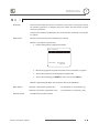
Main Menu
SPEED DOME CAMERA
-----------------------<SYSTEM INFORMATION>
<DISPLAY SETUP>
<DOME CAMERA SETUP>
z System Information
system
information
and
configuration.
z Display Setup
Enable/Disable of OSD display on Main
Screen.
<SYSTEM INITIALIZE>
EXIT
Displays
z Dome Camera Setup
Configure various functions of this camera.
z System Initialize
Initializes system configuration and sets all
data to factory default configuration.
GPT110-IP Instruction Manual
31 G
G
G
G
G
HOW TO USE OSD MENU
4
Display Setup
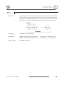
DISPLAY SETUP
-----------------------CAMERA ID
ON
PTZ INFORMATION
AUTO
ACTION TITLE
AUTO
PRESET LABEL
AUTO
ALARM INPUT
AUTO
<SET NORTH DIRECTION>
<PRIVACY ZONE>
BACK
EXIT
This menu defines Enable/Disable of OSD display on Main Screen. If an
item is set to be AUTO, the item is displayed only when the value of it is
changed.
z Camera ID
[ON/OFF]
z PTZ Information
[ON/OFF/AUTO]
z Action Title
[ON/OFF/AUTO]
z Preset Label
[ON/OFF/AUTO]
z Alarm Input
[ON/OFF/AUTO]
Compass Direction Setup
SET NORTH DIRECTION
------------------------
Set North to assign compass direction as criteria. Move camera and
press NEAR button to save.
MOVE TO TARGET POSITION
[NEAR:SAVE /FAR:CANCEL
GPT110-IP Instruction Manual
32 G
G
G
G
G
HOW TO USE OSD MENU
4
Privacy Zone Mask Setup
PRIVACY ZONE
-----------------------MASK NO
1
UNDEFINED
DISPLAY
OFF
CLEAR MASK
CANCEL
<EDIT MASK>
Select area in image to mask.
z Mask No
[1~4]
Select Mask number. If the selected mask has
already data, camera moves as it was set.
Otherwise, “UNDEFINED” will be displayed
under “Mask NO”.
BACK
EXIT
z Display
[ON/OFF]
Sets if camera makes mask shows or not on
images.
z Clear Mask
[CANCEL/OK]
Deletes data in the selected mask NO.
Privacy Zone Area Setup
EDIT MASK 1
------------------------
Move camera to area to mask. Then the menu to adjust mask size will be
displayed.
MOVE TO TARGET POSITION
[NEAR:SELECT/FAR:CANCEL]
Privacy Zone Size Adjustment
EDIT MASK 1
------------------------
[
[
Adjust mask size. Use joystick or arrow buttons to adjust mask size.
z (Left/Right)
z (Left/Right)
z (Up/Down)
z (Up/Down)
:ADJUST MASK WIDTH]
:ADJUST MASK HEIGHT]
[NEAR:SAVE
/FAR:CANCEL]
GPT110-IP Instruction Manual
33 G
G
G
G
G
4
HOW TO USE OSD MENU
Camera Setup
Setup the general functions of zoom camera module.
ZOOM CAMERA SETUPG
------------------------G
FOCUS MODE
SEMIAUTOG
DIGITAL ZOOM
ONG
LINE LOCK
OFFG
IMAGE FLIP
OFFG
<WHITE BALANCE SETUP>G
<AUTO EXPOSURE SETUP>G
z Focus Mode
[AUTO/MANUAL/SEMIAUTO]
Sets camera focus mode.
{ SEMIAUTO Mode
Automatically
BACKG
EXITG
selects
focus
mode
from
Manual Focus or Auto Focus depending on
type of operation. Manual Focus mode
activates in preset operation and Auto Focus
mode activates during jog operation. In
Manual mode, Focus data for each preset is
memorized in advance, and the camera calls
focus data for corresponding presets as soon
as it arrives at a preset.
z Digital Zoom
[ON/OFF]
Sets digital zoom function to ON/OFF. When
set to OFF, optical zoom function runs but
zoom function stops at the end of optical zoom
magnification.
z Line Lock
[ON/OFF]
If Line lock sync is ON, video signal is
synchronized with AC power. Video can be
fluctuated after setting is changed.
zImage Flip
[ON/OFF]
Turn watching direction to the other side of
moving when camera gets vertical sight.
White Balance set up
WB SETUP - GLOBAL
-----------------------WB MODE
AUTO
RED ADJUST
--BLUE ADJUST
---
BACK
EXIT
GPT110-IP Instruction Manual
z WB Mode
[AUTO/MANUAL]
In Manual mode, Red and Blue level can be
set up manually
z Red Adjust
[10~60]
z Blue Adjust
[10~60]
G
34 G
G
G
G
G
4
HOW TO USE OSD MENU
Auto Exposure Setup
z Backlight
[ON/OFF]
Sets Backlight Compensation
AE SETUP - GLOBAL
-----------------------BACKLIGHT
OFF
DAY/NIGHT
AUTO1
BRIGHTNESS
25
IRIS
AUTO
SHUTTER
ESC
AGC
NORMAL
SSNR
MIDDLE
SENS-UP
<AUTO>
BACK
EXIT
z Day/Night
[AUTO1/AUTO2/DAY/NIGHT]
AUTO1 exchanges Day/Night mode faster
than AUTO2.
z Brightness
[0~100]
Adjusts brightness of images. Iris, Shutter
Speed and Gain are adjusted automatically in
correspondence with this value.
z IRIS
[AUTO/MANUAL(0~100)]
If Iris is set to Auto, Iris should have highest
priority in adjusting AE and Shutter Speed
should be fixed.
If Iris is set to Manual, Iris should be fixed and
Iris has lower priority in adjusting AE, in
comparison with others.
z Shutter Speed
[ESC/A.Flicker/Manual(u128~1/120000 sec)]
If Iris is set to Manual and Shutter Speed is set
to ESC, Shutter Speed should have highest
priority. If Shutter Speed is set to A.Flicker, to
remove Flicker, Shutter Speed should be set
to 1/100 sec. for NTSC and 1/120 for PAL.
z AGC
[OFF/NORMAL/HIGH]
Enhances image brightness automatically in
case that luminance level of image signal is
too low.
z SSNR
[OFF/LOW/MIDDLE/HIGH]
Enhances images by filtering noise when gain
level of images is too high.
z SENS-UP
[AUTO(2~128)/OFF]
Activates
Slow
Shutter
function
when
luminance of image (signal) is too dark.
It is possible to set up the maximum number
of frames stacked on one another by Slow
Shutter function.
GPT110-IP Instruction Manual
35 G
G
G
G
G
HOW TO USE OSD MENU
4
Motion Setup
MOTION SETUP
-----------------------MOTION LOCK
OFF
PWR UP ACTION
ON
AUTO FLIP
ON
JOG MAX SPEED
120/SEC
JOG DIRECTION
INVERSE
FRZ IN PRESET
OFF
<PARKING ACTION SETUP>
<ALARM INPUT SETUP>
BACK
EXIT
Setup the general functions of Pan/Tilt motions.
z Motion Lock
[ON/OFF]
If Motion Lock is set to ON, it is impossible to set
up and delete Preset, Swing, Pattern and Group.
It is only possible to run these functions. To set
up and delete these functions, enter into OSD
menu.
z Power Up Action
[ON/OFF]
Refer to Other Functions" section.
z Auto Flip
[ON/OFF]
Refer to Other Functions" section.
z Jog Max Speed
[1q/sec ~360q/sec]
Sets maximum jog speed. Jog speed is inversely
proportional to zoom magnification. As zoom
magnification goes up, pan/tilt speed goes
down.
z Jog Direction
[INVERSE/NORMAL]
If you set this to ೢInverseೣ, the view on the
screen will move in the same direction as jog tilt.
If ೢNormalೣ is selected, the view on the screen
will move in the opposite direction.
z Freeze in Preset
[ON/OFF]
At start point of preset movement, camera will
freeze the image of start point. Camera keeps
displaying the image of start point during preset
movement and does not display the images
received during preset movement. As soon as
camera stops at preset end point, camera will
display live images received at the preset end
point.
Availability of this function will vary by model.
GPT110-IP Instruction Manual
36 G
G
G
G
G
4
HOW TO USE OSD MENU
Parking Action Setup
PARKING ACTION SETUP
-----------------------PARK ENABLE
OFF
WAIT TIME
00:10:00
PARK ACTION
HOME
If Park Enable is set to ON, camera runs assigned function automatically
if there is no PTZ command during assigned "Wait Time".
z Park Enable
[ON/OFF]
z Wait Time
[1~10/15/30 seconds & 1/2/3/4 minutes]
The time is displayed with "hh:mm:ss" format
BACK
EXIT
and can be changed in 1 min units.
z Park Action
[HOME/PRESET/PATTERN/SWING/GROUP]
{ HOME
Camera moves to home position if there is no
PTZ command during assigned "Wait Time".
Alarm Input Setup
ALARM INPUT SETUP
-----------------------ALARM1 TYPE
N.OPEN
ALARM2 TYPE
N.OPEN
ALARM3 TYPE
N.OPEN
ALARM4 TYPE
N.OPEN
ALARM1 ACT
NOT USED
ALARM2 ACT
NOT USED
ALARM3 ACT
NOT USED
ALARM4 ACT
NOT USED
BACK
EXIT
Matches the Alarm sensor input to one of Preset positions. If an external
sensor is activated, camera will move to corresponding preset position
when this item is predefined.
z Alarm u Type
[Normal OPEN/Normal CLOSE]
Sets sensor input type.
z Alarm u Action
[NOT USED/PRESET 1~128]
Assign counteraction Preset position to each
Alarm input.
GPT110-IP Instruction Manual
37 G
G
G
G
G
HOW TO USE OSD MENU
4
Preset Setup
PRESET SETUP
-----------------------PRESET NO.
1
CLR PRESET
<EDIT SCENE>
<EDIT LABEL>
CAM ADJUST
z Preset Number
[1~128]
If a selected preset is already defined, camera
moves to pre-defined position and preset
CANCEL
characteristics such as Label and Relay Outputs
LABEL123
GLOBAL
show on monitor. If a selected preset is not
defined, “UNDEFINED” shows on monitor.
BACK
EXIT
z Clear Preset
[CANCEL/OK]
Delete current Preset data
z Edit Preset Scene
Redefine current Preset scene position (i.e.
PTZ).
Edit Preset Scene
EDIT SCENE - PRESET 1
------------------------
1 Using Joystick, move camera to desired position.
ഗ
2 By pressing NEAR key, save current PTZ data.
ഗ
3 Press FAR key to cancel.
ഗ
MOVE TO TARGET POSITION
[NEAR:SAVE /FAR:CANCEL]
GPT110-IP Instruction Manual
38 G
G
G
G
G
HOW TO USE OSD MENU
4
Swing Setup
SWING SETUP
-----------------------SWING NO.
1
1ST POS.
NOT USED
2ND POS.
NOT USED
SWING SPEED
CLEAR SWING
30/SEC
CANCEL
BACK
EXIT
z Swing Number
[1~8]
Select Swing number to edit. If a selected Swing is
not defined, "NOT USED" is displayed in 1st
Position and 2nd Position
z 1st Position
2nd Position
[PRESET 1~128]
Set up the 2 position for Swing function. If a
selected preset is not defined, "UNDEFINED" will
be displayed as shown below.
SWING SETUP
-----------------------SWING NO.
1
1ST POS.
PRESET5
2ND POS.
NOT USED
UNDEFINED
When swing function runs, the camera will move
from the preset assigned as the 1st point to the
preset assigned as the 2nd point in a CW
(Clockwise) direction. Then the camera will move
from the preset assigned as the 2nd point to the
preset
assigned
as
the
1st
point
in
a
CCW(Counterclockwise) direction. If the preset
assigned as the 1st point is same as the preset
assigned as the 2nd point, the camera will turn
360q in CW direction and then turn 360q in CCW
direction.
z Swing Speed
[1q/sec ~180q/sec]
Sets Swing speed from 1q/sec to 180q/sec.
z Clear Swing
[CANCEL/OK]
Deletes current Swing data.ٻ
GPT110-IP Instruction Manual
39 G
G
G
G
G
HOW TO USE OSD MENU
4
Pattern Setup
PATTERN SETUP
-----------------------PATTERN NO.
1
UNDEFINED
CLR PATTERN
CANCEL
<EDIT PATTERN>
z Pattern Number
[1~4 ]
Selects Pattern number to edit.
If a selected
"UNDEFINED"
pattern number is not defined,
will
be
displayed
under
selected pattern number.
z Clear Pattern
BACK
EXIT
[CANCEL/OK]
Deletes data in current pattern
z Edit Pattern
Starts editing pattern.
Edit Pattern
EDIT PATTERN 1
------------------------
ǗG Using Joystick, move to start position with appropriate zoom. To
start pattern recording, press NEAR key. To exit this menu, press
FAR key.
MOVE TO START POSITION
[NEAR:START /FAR:CANCEL]
ǘG Move camera with controller joystick or run preset function to
EDIT PATTERN 1
memorize a path (often a curved path) in a selected pattern. The
total memory size and remaining memory size are displayed in
the form of a bar. Maximum 1200 communication commands can
be stored in a pattern.
[NEAR:SAVE
/FAR:DELETE]
0/0/x1/N
ཝG To save data and exit, press NEAR key. To cancel recording and
delete record data, press FAR key.G
G
GPT110-IP Instruction Manual
40 G
G
G
G
G
HOW TO USE OSD MENU
4
Group Setup
GROUP SETUP
-----------------------GROUP NO.
1
UNDEFINED
CLEAR GROUP
CANCEL
<EDIT GROUP>
z Group Number
[1~8]
Selects Group number to edit.
If a selected
Group number is not defined,
"UNDEFINED" will be displayed under selected
Group number.
BACK
EXIT
z Clear Group
[CANCEL/OK]
Deletes data in current Group
z Edit Group
Starts editing Group.
EDIT GROUP
EDIT GROUP 1
-----------------------NO ACTION ### DWELL OPT
-----------------------1 NONE
2 NONE
3 NONE
4 NONE
5 NONE
-----------------------SAVE
CANCEL
[NEAR:EDIT]
EDIT GROUP 1
-----------------------NO ACTION ### DWELL OPT
-----------------------1 NONE
2 NONE
3 NONE
4 NONE
5 NONE
-----------------------SAVE
[NEAR:EDIT ACT]
CANCEL [FAR :EDIT END]
ྙG " Press Near key in “NO” list to start Group setup.
ǘG Note that MAX. 20 Functions are allowed in a Group. Move cursor
up/down and press Near key to set up.
ྛG Set up Action, Dwell time and Option. Note that selected item is
EDIT GROUP 1
-----------------------NO ACTION ### DWELL OPT
-----------------------1 NONE
2 NONE
3 NONE
4 NONE
5 NONE
-----------------------SAVE
[ :MOVE CURSOR]
CANCEL [ :CHANGE VAL.]
displayed in reverse. Move cursor Left/Right to select items and
move cursor Up/Down to change each value.
z Action ###G
z DWELL
[NONE/PRESET/SWING/PATTERN]
[0 second ~ 4 minutes]
Sets Dwell Time between functions
z OPT
Option. Displays the preset speed when
preset is set in Action. Displays the number
of repeats when Pattern or Swing is selected
in Action
GPT110-IP Instruction Manual
41 G
G
G
G
G
HOW TO USE OSD MENU
EDIT GROUP 1
-----------------------NO ACTION ### DWELL OPT
-----------------------1 PRESET
1 00:03 360
2 NONE
3 NONE
4 NONE
5 NONE
-----------------------SAVE
[ :MOVE CURSOR]
CANCEL [ :CHANGE VAL.]
EDIT GROUP 1
-----------------------NO ACTION ### DWELL OPT
-----------------------1 PRESET
1 00:03 360
2 NONE
3 NONE
4 NONE
5 NONE
-----------------------SAVE
[NEAR:EDIT ACT]
CANCEL [FAR :EDIT END]
EDIT GROUP 1
-----------------------NO ACTION ### DWELL OPT
-----------------------1 PRESET
1 00:03 360
2 NONE
3 NONE
4 NONE
5 NONE
-----------------------SAVE
CANCEL
GPT110-IP Instruction Manual
4
ྜG Set up items such as Action, ###, Dwell and OPT.
ྜྷG After finishing setup of an Action, press Near key to one-upperlevel menu(Step ྚ). Move cursor Up/Down to select Action
number and repeat Step ྚ ~ Step ྜ to edit selected Groupډ
ྞG After finishing setup of all Actions, press FAR key to exit. Then
cursor should be moved to “SAVE”. Press Near key to save data.
G
G
42 G
G
G
G
G
HOW TO USE OSD MENU
4
System Initialize
z Clear All Data
SYSTEM INITIALIZE
-----------------------CLEAR ALL DATA
NO
CLR DISPLAY SET
NO
CLR CAMERA SET
NO
CLR MOTION SET
NO
CLR EDIT DATA
NO
REBOOT CAMERA
NO
REBOOT SYSTEM
NO
Deletes all configuration data such as display,
camera, motion setup and so on.
BACK
EXIT
z Clear Display Set
Initializes Display Configuration
z Clear Camera Set
Initializes Camera Configuration
z Clear Motion Set
Initializes Motion Configuration
z Clear Edit Data
Deletes Preset Data, Swing Data, Pattern Data
and Group Data
z Reboot Camera
Reboots Zoom Camera module
z Reboot System
Reboots Speed Dome Camera
Initial Configuration Table
z Display Configuration
z Camera Configuration
Camera ID
ON
Focus Mode
SemiAuto
PTZ Information
AUTO
Digital Zoom
ON
Action Title
AUTO
Line Lock
OFF
Preset Label
AUTO
White Balance
AUTO
Alarm Input
AUTO
Backlight
OFF
North Direction
Pan 0q
Day&Night
AUTO2
Privacy Zone
Undefined
Brightness
25
Iris
AUTO
Shutter
ESC
z Motion Configuration
AGC
HIGH
Motion Lock
OFF
SSNR
MIDDLE
Power Up Action
ON
SENS-UP
AUTO
Auto Flip
ON
Jog Max Speed
120q/sec
z User Edit Data
Jog Direction
INVERSE
Preset 1~128
Undefined
Freeze In Preset
OFF
Swing 1~8
Undefined
Park Action
OFF
Pattern 1~4
Undefined
Alarm Action
OFF
Group 1~8
Undefined
GPT110-IP Instruction Manual
43 G
G
G
G
G
CHAPTER
5
Chapter 5.
REMOTE
VIDEO MONITORING
GPT110-IP Instruction Manual
44 G
G
G
G
G
REMOTE VIDEO MONITORING
5
Remote Video Monitoring
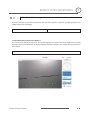
There are two ways to view video between the site and center system. In order for a proper operation, an IP
address must be set accordingly.
Default ID : admin
Default Password : 1234
Video Monitoring using Internet Explorer
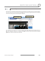
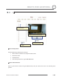
If an encoder’s IP address is entered on the Internet Explorer, the system will ask for confirmation to install
Active-X control. Once authorized, the Internet Explorer will start to display video images from the encoder as
shown below.
http://192.168.10.100
GPT110-IP Instruction Manual
45 G
G
G
G
G
5
REMOTE VIDEO MONITORING
Remote controller in live view
-View Size : Change screen size according to your monitor.
Default value is ‘x1’ and this means original size.
CLICK
-Moving control : place your mouse in the circle and click. PTZ
moves on that way
-Zoom In/Out(Tele/Wide) : zoom in & out current watching.
-HOME : Move to home position. *for more details, see ‘Motion
Setup->Park Action’ setup.
-Focus Near/Far & auto focus button : only works on ‘Manual
focus’ setup. *Not working if it is on ‘auto focus’ status’.
-IRIS Close/Open & Auto Iris : Close Iris on high light condition
and open in low.
-MENU ON : display text menu of IP CAMERA
-Enter : Enter selected menu.(SAVE)
-ESC : cancel current setting and exit to previous page
Set preset position : 1. Place camera on your desired place. 2.
Select preset number. 3. Press set.
Move to preset position : 1. Choose preset number, 2. Press
‘GOTO’ button. *use ‘clear’ button to remove preset position
Select the number of tour and type(pattern, Swing, Group) * this should be defined first in each
menu(see operation page, pattern, Swing, Group)
Snapshot : snapshot on current live image as still cut.
Talk : voice talk over connected devices. * Camera only can send sound to client. To hear the sound
from camera, you should connect microphone on camera and speaker on Remote.
GPT110-IP Instruction Manual
46 G
G
G
G
G
REMOTE VIDEO MONITORING
5
Initialize IP address
If a system IP address is lost, the system can be reset to the system default IP address using the reset button in
the back side of the system.
ཛ
While system is in operation, press the reset button for more than 5 seconds.
ཛྷ
The system will reboot automatically
ཝ
Once the system reboots, IP address will be set to the system default as below.
x IP mode
Fixed IP
x IP address
192.168.10.100
x Subnet mask
255.255.255.0
x Gateway
192.168.10.1
x Base port
2222
x HTTP port
80
GPT110-IP Instruction Manual
47 G
G
G
G
G
5
REMOTE VIDEO MONITORING
IP finder in remote client
To use IP camera over network, you should set IP address first on your IP camera.
T
Prepare Network cable
T
Connect to available Network port.
T
Find IP address of the network camera with IP installer or IP remote s.w
* IP installer : Find IP address of registered device, update and web connection
IP finder
IP
finder
searches
all
available
devices on connected network.
(Available menu is differ to each
model)
To find your device, click ‘Search’
button and then you can do following
process.
-Configuration : Change IP address
-Upgrade : upgrade firmware
-Time zone : change time zone
-import
setup
:
import
setup
configuration files
-Web connection : Connect through
I.explorer.
After Searching, select a device and change IP address according to your network information and connect through
‘Web Connect’.
GPT110-IP Instruction Manual
48 G
G
G
G
G
REMOTE VIDEO MONITORING
5
IP Finder Configuration
Configuration
In Configuration page, user can setup connection type and IP address information.
- DHCP : Once you select DHCP, it disables IP address information field. To use this option, you must check
your network support DHCP.G
- PPPoE : Use this option when you use WAN service. To use WAN service, you need ID & Password from your
service provider.G
- Static IP : if you know all IP information, select this option.
- Use DDNS : check this option when you use DDNS service.
- Port : shows port numbers which required in communication.
Web connect
Access directly to camera with Internet Explorer and user can do remote setup. See more details on next
page.
GPT110-IP Instruction Manual
49 G
G
G
G
G
REMOTE VIDEO MONITORING
5
G
Use Internet Explorer
G
The server can be configured using web browser. Type IP address in the address input area of Internet Explorer,
then a live viewing screen will be displayed. Press Setup button located in the upper right area of the monitoring
screen, then the setup page for server setup will be displayed.
c Enter IP address
d Press Setup button
The configurations are grouped into 8 categories: System, Video, Audio, Network, Serial, Event, Preset and
User. Any configuration changes are not applied until Apply is pressed. Leaving the page without pressing
Apply button, changes in the page will be discarded.
GPT110-IP Instruction Manual
50 G
G
G
G
G
REMOTE VIDEO MONITORING
5
System
G
G
G
G
G
G
G
G
G
G
G
G
G
G
G
G
G
G
Video Standard
Select NTSC or PAL
System ID
Alphanumeric System ID to be transferred to remote software
Language
Language to be used for web-based configuration(English, Japanese and Korean)
Firmware version
Current firmware version
Start Time
Latest system boot date and time
Current Time
Enter a new date and time and press Set Current Time button to update date & time
Time Zone
Select time zone of where the system is installed. Depending on the time zone,
Daylight Saving Time will work automatically
Automatically
synchronize with
Synchronize system time with an NTP server using NTP(network time protocol).
Name of the NTP server should be registered on NTP server Name.
NTP server
Reboot Server
Pressing Reboot Server button will cause the system to reboot. Do not press the
Reboot button unless the server needs a reboot.
Factory Reset
GPT110-IP Instruction Manual
Back to default(factory default)
51 G
G
G
G
G
REMOTE VIDEO MONITORING
5
Video
G
G
Preference
Preference in video compression and transmission: With ‘Bitrate’ selected, the video
compression will be effected by the ‘Bitrate’ value entered. With ‘Quality’ selected,
the video compression will be effected by the quality of image selected. Therefore,
‘Bitrate’ and ‘Quality’ corresponds to CBR and VBR respectively
Resolution
Selectable video compression resolution:
NTSC: 720u480, 720u240, 352u480, 352u240
PAL: 720u576, 720u288, 352u576, 352u288
G
GPT110-IP Instruction Manual
52 G
G
G
G
G
REMOTE VIDEO MONITORING
5
G
Frame rate
Selectable video frame rate: Determine the maximum number of frames of video
images to compress. The frame rate of actually transmitted video can be affected by
the network bandwidth limitation
Quality
The selection is possible with Preference is set to ‘Quality’
Bitrate
The value is applicable when Preference is set to ‘Bit rate’
I-Frame Interval
Possible values between 0 and 255. There will be no I-frames if 0 is selected.
Motion Detection
Configure regions for motion detection. Regions of arbitrary shape can be
Area Editing
configured by the following steps.
ཛG Enable Edit item.
ཛྷG Select editing Mode. Set is for including cells to motion detection region and
Erase is for excluding.
ཝG Select cells using the left button of the mouse. Multiple cells can be selected
conveniently by press and dragging.
ཞG Press Apply Edited Area to save the editing.
Sensitivity
A condition to trigger an event with motion detection. The value determines the
sensitivity of the motion detection within a block: the smaller, the more sensitive
Brightness
Controls input video brightness by selecting values between 0 and 100.
Contrast
Controls input video contrast by selecting values between 0 and 100
Hue
Controls input video Hue by selecting values between 0 and 100
Saturation
Controls input video saturation by selecting values between 0 and 100.
Burn-in OSD
Inserts system ID and date/time in the compressed video. Separately System ID and
Time can be turned On or Off in the video. Position specifies the position of such
data
GPT110-IP Instruction Manual
53 G
G
G
G
G
5
REMOTE VIDEO MONITORING
Audio
G
Mode
Input Gain
GPT110-IP Instruction Manual
Select audio operation mode
Mode
Action
Off
No operation
Tx-Only
Transmit only
Rx-Only
Receive only
Tx & Rx
Transmit and Receive
Set audio input gain
54 G
G
G
G
G
REMOTE VIDEO MONITORING
5
Network
G
GPT110-IP Instruction Manual
55 G
G
G
G
G
5
REMOTE VIDEO MONITORING
IP Mode
Three IP modes are supported. Depending on the selected mode, further
configuration items come as follows.
IP Mode
Selection
Fixed IP
Local IP
Description
Fixed IP address
Local Gateway
Gateway IP address
Local Subnet
Subnet mask
൯ Please ask an IP address information from ISP provider or network manager
DNS
Set DNS server IP address.
PORT
Base Port : communication port for each connection.
HTTP Port : web port(Default is 80)
RTSP Port : default 554
RTSP Auth.
RTSP Session
SNMP
Bitrate control
Use when you need RTSP authentication
4
Communication protocol setup for RTSP use.
Communication protocol to detect network status
When several clients connect to a server, bandwidths of networks clients may differ
and some clients may not receive encoded stream fully. To handle such situation,
three flow control modes which can be chosen according to users’ preference are
provided
Mode
Description
Min
The bitrate is automatically adjusted to a client with smallest
network bandwidth
Max
The bitrate automatically adjusted to a client with largest
network bandwidth size. When set to this mode, a client with
smaller bandwidth will not receive all frames of video
Adjust
The bitrate is adjusted to most optimum rate by learning the
Off
Flow control is off
network bandwidth
Address Info
Display network related information
IP Address
The server own IP address. This information is useful when the
server’s IP mode is set to DHCP
Current
In case the server is registered with DDNS server, the registered
Domain
domain name is displayed
MAC
Display the MAC address of the server. In case the server is
Address
registered with DDNS server, the MAC address is used in DDNS
4
registration
G
G
GPT110-IP Instruction Manual
56 G
G
G
G
G
REMOTE VIDEO MONITORING
5
Serial
G
This page is used only for developer and test purpose. In this page, user can define serial connection of camera and
this is only used when user control camera as RS485 telemetry. No available in IP connection control
G
G
RS485 port
Set connection type with each connection information. To get detail of RS-485
connection, refer to PTZ camera’s instructions.
PTZ
Set PTZ type and ID according to configured setup.
G
QSerial communication information should be synchronized to Analog camera communication setup.
GPT110-IP Instruction Manual
57 G
G
G
G
G
REMOTE VIDEO MONITORING
5
G
Event
G
In this page, user can define alarm activity and notification from local to remote.
Local
Define what type of reaction in local followed by each event. There are E-mail, FTP and
Move to preset position option.
On Disconnect
Define what type of reaction will be on when system is disconnected.
E-mail
Set mail server information to send out e-mail to specified user. Check if you will
Notification
include Video Clip or not.
FTP upload
Set FTP server to upload event triggered image data.
Event Record
Set PRE & POST Recording time and POST Event type.
GPT110-IP Instruction Manual
58 G
G
G
G
G
REMOTE VIDEO MONITORING
5
Preset
d Preset Name
c Move Camera to normal view
e Press Set Button
f Save
Preset Configuration
Set the PTZ Presets by following the next steps.
ཛG Move cameras to desired view using PTZ control buttons.
ཛྷG Enter Preset name.
ཝG Press Set button.
ཞ
Once all the presets are set, press Save List button.
Move to Preset Position
Select a preset from the Preset and press Go To button, then, the camera will move to the selected preset
position.
GPT110-IP Instruction Manual
59 G
G
G
G
G
REMOTE VIDEO MONITORING
5
User
G
User can be registered and authority level of a user can be specified. User configuration is allowed only to
admin user. MAX. 16 users can be registered and each user can have one of four authorities.
Authority Level
Allowed Operations
Admin
All operations
Manager
All operations except for user configuration
User
Live viewing and PTZ control
Guest
Live viewing only
Remarks
User ID = admin
Add User
Page for adding a user comes on pressing Add button.
GPT110-IP Instruction Manual
60 G
G
G
G
G
REMOTE VIDEO MONITORING
5
User ID and password need to be entered and privilege level need to be selected. User ID and password consist
of alphanumeric string of MAX. 15characters.
Delete User
A user is deleted by pressing Delete button.
Change Password
Pressing Modify Password button after selecting a user shows a page for changing password. In case of
changing admin password, the old password is checked.
Modify Privilege Level
Pressing Modify Privilege button after selecting a user shows a page for changing the authority. It is not
allowed to change the authority level of admin user.
Login Policy
Skip Login is provided for convenient access to the server when authentication is not required. When Skip
Login is set to Enable, login step is skipped. The privilege level after login in this way is determined by the
setting of
Privilege Level After Login Skipped.
GPT110-IP Instruction Manual
61 G
G
G
G
G
CHAPTER
6
Chapter 6.
SPECIFICATION
GPT110-IP Instruction Manual
62 G
G
G
G
G
SPECIFICATIONS
6
Specifications
Network Interface
Ethernet 10/100 Base-T(RJ45)
Network Protocol
TCP/IP,UDP, Multicast, DHCP, PPPoE, SMTP, HTTP, SNMP
Standard
H.264
Network
Data Rate
32Kbps ~ 4Mbps
NTSC
: 720u480, 720u240, 352u480, 352u240
PAL
: 720u576, 720u288, 352u576, 352u288
Resolution
Video
Audio
Max Frame Rate
NTSC
: Max. 30fps
PAL
: Max. 25fps
Frame Rate Range
NTSC
: 0.2 ~ 30fps
PAL
: 0.2 ~ 25fps
Motion Detection
Sensitivity adjustable
Standard
G.711
Sample Rate
8KHz
Data Rate
64Kbps
Input
1 Line-In (Mini-Stereo)
Output
Video Access from Web-Browser
1 Line-Out (Mini-Stereo)
Camera Live View & Audio/Video snapshot, PTZ control, Remote
Setup, Remote Upgrade
Multiple user access levels with password protection, IP address
Security
filtering, HTTPS encryption, IEEE 802.1u authentication
Max 36 Channel Monitoring simultaneously
PTZ Control
Live Monitoring
Event Monitoring
Bi-directional Audio communication
CMS
Time/Camera-Base/Event-Base
Search/Playback
Multi-channel viewing of recorded status on timeline
Export to AVI file
Backup
Snapshot to BMP file
GPT110-IP Instruction Manual
63 G
G
G
G
G
SPECIFICATIONS
Model
PT110N
Video Signal System
NTSC
CCD
1/4'' Interline Transfer CCD
Max. Pixels
811(H)u508(V) 410K
Effective
Pixels
Horizontal
Res.
768(H)u494(V) 380K
500 TV Line(Color), 570 TV Line(B/W)
S/N Ratio
50 dB (AGC Off)
u10 Optical Zoom, u10 Digital Zoom
Zoom
Camera
Focal length
F1.8, f=3.8~38mm
Min.
illumination
0.7 Lux (Color) / 0. 02 Lux (B/W), 50 IRE
Day & Night
Auto / Day / Night(ICR)
Focus
Main Unitٻ
x128 ~ 1/120000 sec
AGC
Normal / High / Off
White
Balance
Auto / Manual(Red, Blue Gain Adjustable)
BLC
Low / Middle / High / Off
Flickerless
Selectable
SSNR
Low / Middle / High / Off
Range
Pan :
360q(Endless)
Tilt :
180q (Auto-Flip), 95q (Normal)
Preset :
Manual :
Swing :
360q/sec
0.05 ~ 360q/sec (proportional to zoom)
127 Preset (Label, Camera Image Setting)
Pattern
4 Pattern, 1200 commands(about 5 minute)/Pattern
Swing
8 Swing
Group
8 Group (20 action entities per Group)
Auto Flip, Auto Parking, Power Up Action etc.
Communicati
on
Protocol
RS-485
Pelco-D, Pelco-P selectable
Privacy Zone
4 Zone
Alarm Input
4 Input
OSD
Rated
Power**
Dimension
Weight
Operating
Temp.
Pendant Mountٻ
1~ 180q/sec
Preset
Other
Functions
General
G
G
G
G
G
G
G
G
G
G
G
Auto / Manual
Shutter Speed
Pan/Tilt
Appearance
Auto / Manual / SemiAuto
Iris
Pan/Tilt
Speed
6
Wall Mountٻ
Menu / PTZ information etc
DC Type :
Dome :
Housing :
DC 12V / 1.3A
115
154.5 u 158.5(H) mm
about 1.3 Kg
0qC ~ 40qC
* Specifications of this product are subject to change without notice.
** Check the voltage and current capacity of rated power carefully.
GPT110-IP Instruction Manual
Flush Mountٻ
64 G
G
G
G
G
SPECIFICATIONS
6
Dimension
z Main Unit & Surface Mount Bracket
z Pendant Mount Bracket
z Wall Mount Bracket
measurement (mm)G
GPT110-IP Instruction Manual
65 G