1
Video Input
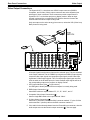
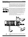
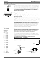
Rear Panel Connections
Input Configurations
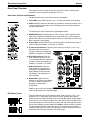
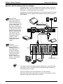
Each System 8/10 PLUS switcher input can be configured for any of the following
RGB connections:
•
•
•
•
•
RGB - Red, Green/sync, Blue (3 cables)
RGBS - Red, Green, Blue, and Composite Sync (4 cables)
RGBHV - Red, Green, Blue and Separate H & V Sync (5 cables)
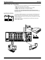
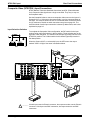
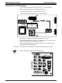
Composite (NTSC/PAL) - Using the G connector (1 cable)
S-Video/S-VHS - Using the G connector for Y and H/HV connector for C
(2 cables)
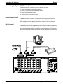
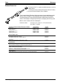
All video inputs to the System 8/10 PLUS use BNC connectors. Many types of
video devices (VCR, laserdisc players, some computers, etc.) do not have BNC
video output connectors. For this reason, an adapter may be required to connect
the device output to the BNC input of the System 8/10 PLUS. (See parts list in
Appendix B.) With the proper adapter, the RGBS signal can be connected
directly to the R, G, B, H and V inputs of the switcher. If the RGB signal is
carrying the sync on the green channel, connect the three RGB cables to the
switcher without using the sync channels. Audio connections may be used with
any of these video inputs.
Input Switches and Output LEDs
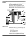
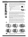
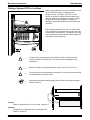
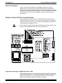
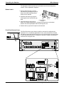
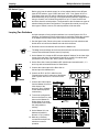
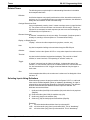
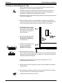
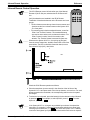
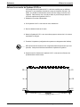
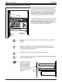
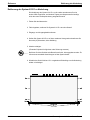
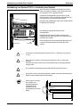
When configuring an input, the video mode must be set up in the DIP switches
located above the output connectors. There are two banks of eight (or ten)
switches. The left bank is for S-Video and the right bank is for Composite
(NTSC/PAL) video. One switch in each bank is assigned to an input channel
number. For example, input #1 uses the leftmost switch at each bank. For the
video mode shown on this page, DIP switch #1 of each switch bank must be in
the RGBS position, which is in the down position.
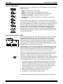
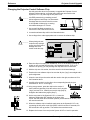
The System 8/10 PLUS switchers are shipped with all DIP switches in the down
position (RGBS inputs). For composite video input, change the NTSC/PAL DIP
switch for that input channel to the up position. For S-Video or S-VHS input,
change the S-Video/S-VHS DIP for that input channel to the up position.
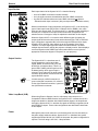
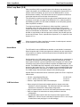
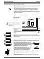
There is an Output LED next to each set of output connectors. When an input is
selected, the Output LED indicates the format for which that input has been
configured. This also informs the user which output should be used.
_____ These output LEDs also serve as a configuration check. Also, for displays which
have all of their signals (including S-video and Video) on the RGBHV port, both
the RGB LED and either the S-video or Video LED will light simultaneously.
1. For example, if input #1 is using RGBS, and DIP switch #1 of the S-Video
bank was accidently switched “up”, then the S-Video output LED will be lit,
instead of the RGBS LED. This informs the user of an improper setting.
2. The only conditions for which two output LEDs can be lit at the same time is
when the System 8/10 PLUS is used in the Video Loopback mode.
3. Under normal conditions, one of the output LEDs should be lit.
4. All three output LEDs should never be lit at the same time.
5. If no LEDs are lit, check for proper switch settings.
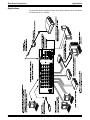
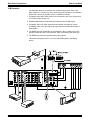
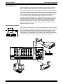
The following pages show examples of the three possible input configurations.
Extron • System 8/10 PLUS • User’s Manual
2-4