1
EasyLoader
AV-2016D, AV-2016DP
AV-2055D, AV-2088D
(for LED keypad)
Integrated Alarm Control/Communicator
Installation and Operation Manual
Version 3.05D
Edition II
This product is subject to continuous enhancements and therefore
specifications may be changed or altered without prior notice
Item: 4712_BIG (A4BKE)
1
Table of Contents
Contents
Page
SECTION I: SYSTEM FEATURES .................................................................................. 4
1. INTRODUCTION...................................................................................................... 4
1.1 General Description...................................................................................... 4
1.3 Programmable Features ................................................................................ 5
1.4 Alarm and Power Outputs ............................................................................ 5
1.5 Ordering Information.................................................................................... 7
1.6 AV-2016D, AV-2055D, AV-2088D Technical Specifications.................... 8
SECTION II: INSTALLATION...................................................................................... 10
2. MOUNTING .............................................................................................................. 10
2.1
2.2
2.3
2.4
Control Panel Mounting ............................................................................... 10
Connection of AV-816 Expander................................................................. 12
AV-2055, 2088D Wiring.............................................................................. 13
Keypad Wiring ............................................................................................. 14
3. ALARM OUTPUTS .................................................................................................. 16
3.1
3.2
3.3
Sirens ............................................................................................................ 16
Remote Indication Terminals ....................................................................... 16
Wiring and Connection of Relay Module..................................................... 17
4. WIRING AND POWERING UP ............................................................................... 18
4.1
4.2
4.3
4.4
4.5
4.6
4.7
4.8
Grounding – Lightning Protection................................................................ 18
Back-up Battery............................................................................................ 18
Before Powering Up ..................................................................................... 18
Connecting Smoke Detectors ....................................................................... 19
Telephone System Dialing............................................................................ 20
SVM – Voice module................................................................................... 20
Remote Key and Wireless Arming & Disarming ......................................... 21
Remote Access via DTMF ........................................................................... 21
SECTION III: AV-701 & AV-702 DIGITAL KEYPAD............................................... 23
1.1
1.2
1.3
1.4
1.5
1.6
Standard Keypad Functions.......................................................................... 23
Hold-Down Functions .................................................................................. 25
Keypad Sounder ........................................................................................... 29
LED Indicators ............................................................................................. 30
Keypad Digital Display (7-segment type) .................................................... 31
Arm and Disarm System via AV-701/702 Series Keypad ........................... 32
2
SECTION IV: PROGRAMMING ...................................................................................... 34
1. SYSTEM CODES...................................................................................................... 34
1.1 User Code Programming via AV-701 Keypad (Not with AV-2016DP) .......... 35
2. FEATURE PROGRAMMING AT INSTALLER LEVEL ........................................ 36
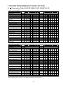
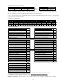
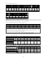
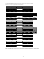
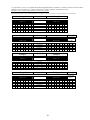
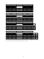
2.1 Programming Table AV-20055D, 2088D, 2016D, 2016DP (V3.05)........... 36
2.2 Introduction .................................................................................................. 44
2.3 Programming Sheet Explanation.................................................................. 44
2.4 Glossary of Programmable Features............................................................. 46
2.7 Step - By - Step Programming...................................................................... 51
2.8 Reset System to Default Programming ........................................................ 55
2.9 Dialer- Communicator; explanation and Programming ............................... 55
2.9.1 Deleting Telephone Numbers ........................................................................ 56
2.9.2 User Programming of ‘Follow-Me’ Telephone Number ............................... 57
2.10 Quitting Programming Mode.......................................................................... 57
2.11 Verification of Current Programming............................................................. 57
2.12 Downloading from a computer ....................................................................... 57
3. PARTITIONED SYSTEM – TYPE AV-2016DP...................................................... 63
3.1 Partition Definition ........................................................................................... 63
3.2 AV-2016DP - Users Options ............................................................................ 64
3.3 AV-2016DP - Keypad Operation...................................................................... 64
3.4 AV-2016DP - ‘Hold Down’ Keypad Functions ............................................... 66
3.5 AV-2016DP LED Indicators............................................................................. 68
3.6 System Codes.................................................................................................... 68
4. TROUBLESHOOTING ............................................................................................. 69
SECTION V: WIRING DIAGRAM ........................................................................................ 73
SECTION VI: INDEX ........................................................................................................... 74
Av-Gad Limited Warranty........................................................................................... 76
@ All Rights Reserved to Av-Gad Systems Ltd, Tel Aviv, Israel. POB 49 080 Tel-Aviv, Israel. February 2013/ VER. 3.05D Rev 1, /2016_2088_2055 3.05. Item 4712_BIG
3
SECTION I: SYSTEM FEATURES
1. INTRODUCTION
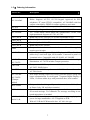
1.1 General Description
Av-Gad's EasyLoaderTM AV-2055D, AV-20088D, AV-2016D, AV-2016DP are
microprocessor based intruder alarm panels with integrated communicator. They feature 5, 8,
16 or 32 double-zone all of them are expandable and compatible to Av-Gad LED keypads.
Series 2000 represents the state-of-the-art in user-friendly, reliable alarm control panels for
security requirements of small and medium-size commercial, residential, and industrial
installations.
Av-Gad's EasyLoaderTM AV-2016 and AV-2008 versatile control panels meets, surpasses all
requirements for reliability and maintainability, and provides the added benefits of easy
installation and simple operation.
The Dublo Version is an upgraded model of the AV-2016, designed to be compatible with
AV-705, 706, 707 and AV-707B LCD (English Text) keypads. Refer the AV-2016 Dublo
manual.
The AV-2016 comprises an enhanced power supply, improved electronics, and additional
signaling indicators.
The 2000 Series innovative keypads (AV-701 & AV-702) are unquestionably the most userfriendly remote station, designed to enable control of the system by the end-user, as well as by
the installer.
Version 3.00 news
Version 3.00: The Spare output (2016) terminal removed, DTMF control (arm, disarm, etc)
is standard, panel version identifies itself as AV-2016D (EasyLoad software), self test at
initialization (STI) - Dial LED blinks for the first 50 seconds after power on, new factory
defaults, address 052: Set the signal test per days, improved lighting protection with option for
heavy duty lighting protection, CS testing day programming. Home Automation: Activation of
A1 and SLO outputs via DTMF, First alarm indication reported via DTMF.
Version 3.04: New at 072-4, activate ON output to drive ADSL filter line disconnect, added
999 to exit programming mode, during Answer Now mode keypad display CA, improved
Contact ID format. New AV-2016 box is ready for extra AV-21 power supply and 5003TER
transformer. Version 3.05: Enable Last Zone as Aux. Key, including AV-2055D, AV-2088D.
Version 3.05A: Code 8 problem fixed. Version 3.05C: Siren wiring in case of troubles, see
section 3.1.
4
1.2 Built-in Features
Accepts Normally Closed or Normally Open alarm devices
All features are programmable via system keypad
Automatic battery test upon arming and during Disarmed or Armed mode
True low battery indication
Central station communicator and dialer. Communicator is compatible with most major
formats: Ademco Slow and Express, Radionics, Scantronic, Sescoa, Contact ID, etc
Chime programmable for each zone
Digital zone status display
Double-Pole zones. Tampering indication for each zone
Eight partitions with the AV-2016DP, compatible with LED keypads only
Keypad sounder during local alarm
Local clock and date
Modulated tone siren from 24H and panic zone(s), 3-tone alarm from burglary zones
Programmable four or five output drivers for remote signaling and reset of smoke detectors
Programmable 16 or 32 EOL resistor zones, or non-EOL zones
Pulse-operated battery charging circuit
Two dialing modes: Pulse or DTMF. Dialing to pagers in Hong-Kong and Singapore
Signals to central station monitoring (via wire or wireless)
Up and Download from a computer, or via telephone line
Up to 250 alarm logs, with event time
Up to 8 or 16 user codes, each code one to six digits. One installer code, access control code
Up to 32 (2016) EOL supervised double-zone. One Panic zone at keypad
1.3 Programmable Features
Thirty-two End-Of-Line zones (with AV-816), EOL zone enable or disable
Individual entry delays for two zone groups.
Automatic bypass of open (troubled) ‘instant’ zones upon arming
Selective and Zone Group Bypass (Group Shunt for Home Mode)
24-hour zones, fire zone
Zone types: Delayed, Follower, Fire, Not in use, Day, Tamper, Panic zone and more
Selectable response time for individual zones
1.4 Alarm and Power Outputs
Five programmable open collector output drivers for remote alarm signaling
Contains auxiliary output for electric strike operation
Communicator to central station and alarm sound dialer
Keypad sounder alarm programmable by zone
Two timed siren outputs, protected by separate fuses
Variable sirens alarm sound for different types of zones
Two separate fused protected auxiliary power (12V) outputs
5
Signal test to central station, signaling time and day are programmable
Programmable ‘Bell Mode’
SPR output toggle mode via hold down key
Remote Signals:
24H-zone Alarm
On/Off (Arming/Disarming) indication
Central station Signal Test. Transmitting time is programmable
Panic, Tamper alarm
Programmable output for each zone or event (SLO output)
6
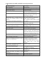
1.5 Ordering Information
Item Code
Description
AV-2016D
AV-2016D4F
AV-816
16 + 1 double-zone Alarm Control Panel and Communicator/
Dialer. Supports AV-701, AV-702 keypad. Approved for EEC
telephone (“E” mean CTR-21 compatible). AV-2016D4F with four
outputs controlled by DTMF for remote appliances activation
16 zone expanding module compatible with AV-2016
AV-208
8 zone expanding module compatible with AV-2055, 2088D
AV-2016DP
2055_4PCB
16 + 1 zone Alarm Control Panel and Communicator / Dialer, with
eight partitioned. Supports AV-701, AV-702
Board only for AV-2055D (5 or 10 zone expandable to 26)
2088_4PCB
Board only for AV-2088D (8 or 16 zone expandable to 32)
2016P_4PCB
Board only for AV-2016DP
2016_4PCB
Board only for AV-2016D
TMP
Tamper switch with wires for main alarm metal box. Not supplied,
requires special order
4-wire Keypad. 7-segment Digital Display, 4 LEDs, 12 silicon
rubber keys, semi-back light, local sounder. Connected to panel via
4 terminal wires. Compatible with AV-2016D, AV-2016DP
Identical to AV-701TS, with additional timed backlight
illumination. AV-701TP includes Tamper protection
AV-701TS
AV-701TI
AV-701TP
5003TER
5005TER
AV-702 and
AV-702TP
(Tamper
added)
RELAYMO
SVM-40/60
AV-21, AV-21B
and AV-40
Fuse-protected 220V step-down to 16V-1.2A AC transformer for
AV-2055, 2088D Series
Fuse-protected 220V step-down to 16V-1.7A AC transformer for
AV-2016 Series
New shape housing. Improved circuitry provides longer wiring and
better communication. 4-wire Keypad. 7-segment Digital Display, 4
LEDs, 12 silicon rubber keys with protection door, local sounder
Relay module for driving self-powered siren in Series 2000. (Used
in France, Italy, UK and other countries.)
Speech module, record & play, message stored without power, 40 or
60 seconds message. Two channels. For message recording an onboard microphone is included
Extra 12V-1A or 4A, power supply and charger, supplying the
power for large installations. AV-21 supplied as PCB.
With AV-21B the PCB housed in box. AV-40 is 4A type
7
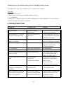
1.6 AV-2016D, AV-2055D, AV-2088D Technical Specifications
Operating Temperature
Relative Humidity
Input AC Power
Dynamic Inner Memory
Auxiliary Power Output
-10C to 60C
80% maximum
16V AC step-down Transformer 1.7 Amp
EPROM and SRAM
13.8 Volts +/- 5%, Regulated
Short & Overload circuit protection
Siren Outputs (x2)
Siren or Bell Selectable
Bell Mode: 14V DC-2 x 0.7A (1.4A)
Siren: 8 Ohms, 20W Max.
Programmable Dialer: 3 telephone numbers & Pulse Dialing parameters programmable
1 Follow Me telephone number (4 phone DTMF: Touch Tone dialing
numbers)
Max. Telephone number length: 16 digits
Multi-format central-station communicator
and 4 pauses
Remote Indications on Wire Terminal
Open Collector type output
300 mA Max. @ 12V DC
EOL Zone Loop Resistor (Burglary)
2,200 Ohms, 0.25W, +/- 5%
EOL Zone Loop Resistor (Tamper)
4,700 Ohms, 0.25W, +/- 5%
Zone Loop Voltage
5 to 6.5V DC
Zone Loop Current
3 mA with End-Of-Line Resistor
Line Protection
Zone line shorting, cutting, high voltage
lightning protection, RF Metal Screen,
Electro Static Discharge Traps, RF Filters.
Telephone line Lighting protection circuit
Auxiliary Power (Max.)
13.8V DC 1.4A Combined AUX. Power
and Keypad outputs 13.8V DC-0.6A
Battery Charging Current (Max.)
550 mA, current limitation
Battery Test: Indication at keypad or remote Performed at 0.5A load for 1 second.
indication via communicator
Low Battery indication below 10.5V
Tested upon Arming, and every 4 minutes
during Armed, every 1 hour during
Disarmed
Standby Power Consumption at disarmed
110 mA, +/- 10 %
mode, and Keypad display is Off
Max. Remote Station (Keypads)
Five keypads AV-701TS, AV-701TI, AV702. Eight AV-707 keypads
Remote Station Current Consumption
AV-701TS: 27mA. AV-701TI: 36mA
AV-702: 40mA.
Housing (AV-2055D, AV-2088D in ABS ABS plastic
plastic box)
Housing Dimensions (AV-2016D)
(H) 32, (D)9, (W)36 cm
Housing Dimensions (AV-2055D, 2088D)
(H) 30, (D) 9, (W) 23 cm
8
Gross Shipping Weight (2055D, 2088D)
Gross Shipping Weight
Fuses: Electronic Fuse
AV-2000: 1 kg. Six units per master box
AV-2016: 3.6 kg. Three units per box
Auxiliary Power: 1.5A Electronic
Keypad Power (2016): 1.5A Electronic
Sirens: 1.5A Electronic
Backup Battery Fuse: 3A Electronic
Av-Gad Systems Ltd. reserves the right to modify and upgrade products without prior notice.
Electronic Fuse Overview
The Electronic Fuse device included as a series element in electric circuit. In response to an over current it
protects the circuit by going from a low-resistance to a high-resistance state that reduces the current to a level
that’s safe for the circuit elements. The change in resistance is the result of a rapid increase in the
temperature of the device. Like traditional fuses, Electronic Fuse devices interrupt the flow of dangerously
high current. However, unlike traditional fuses, they automatically reset after the fault cleared and power to the
circuit removed. Because they are solid-state, Electronic Fuses are also better able to withstand mechanical
shock and vibration, and provide reliable protection in a wide variety of applications. In case of over current,
carefully touch the fuse body (yellow round disc), hot body means the Electronic Fuse in protection mode,
disconnect the load and wait 2-3 minutes until the fuse body get cooler.
Tips to first time installer
If you are a first time installer, do not hook up any remote sensors at first. The most common
confusion comes about when the alarm will refuse to arm, because a zone is “troubled”.
Complete the power supply, siren, keypad and strobe wiring, and for the moment connect ALL
the zone terminals to –V. This will simulate a system with all zones looped out through closed
switches. The alarm is supplied already programmed with an “average” list of settings (default)
and can be used straight away, a few of the program locations may have to be changed to suit the
actual sensors and output devices used.
Read this manual carefully, it looks complicated, but all the information is there
The AV-2055D, 2088D, 2016D and AV-2016DP support LED keypad only; do not connect LCD keypad
To start with: Hook up the keypad, connect all zones to –V, power-up by applying AC only
In case the keypad (LED or LCD) displays ‘garbage’ verify the minus (-V) wire connection
Arm and disarm the system, when the Status LED light (not blinking), enter your master code; 1234
Try the hold-down functions. Hold each key for approximately 2 seconds; follow the confirmation letters
in keypad’s display. In the PRO panel press the # to confirm the hold down command
Set the system time by holding-down key ‘0’ then ‘1’, set time in 24H format, blinking ‘h’ stop
The default programming is set for siren alarm device that requires 12V to alarm (Bell Mode)
Connect the Strobe Light to the SLO output (requires programming). The SLO supplies –V during alarm
Make sure you are using the Earth terminal
for Grounding; it is not a minus terminal
Typing six erroneous codes will lock the keypad keys for 30 seconds
Fast test: Verify “Dial LED" self test at initialization (STI) - Blinks for the first 50 seconds after power on,
confirms panel is operative, from keypad wait to six beeps to confirm communication OK.
9
SECTION II: INSTALLATION
System planning
When the panel reaches you features set at “Factory Defaults”. This done for testing purposes
and for simple installation without first entering to programming. This present program is
referred to as ‘Factory Defaults.’ The engineer should be familiar with all the features and
options before attempting to program. System supplied with or without transformer according to
approval requirements in each country. Specify and order the keypad (several types available).
Default arming code is 1,2,3,4. Default programming code is 1,9,9,4.
2. MOUNTING
2.1 Control Panel Mounting
Refer to detailed wiring diagram on section V. Note: ‘h’ is displayed after power-up to remind
installer and user to set the system time; ‘h’ sign disappears after time setting (by hold down
keys 0 then hold down key 1, refer to page 26).
Select a mounting location accessible to the following:
1. A continuously powered (non-switched) AC power source, compatible with step-down
transformer. Make sure the mains (110 or 220V) are fused
2. A cold water pipe Ground, ideally no farther than 3 meters (10 feet) from the panel. Use
16 AWG (0.5 mm2 wire)
3. Telephone line socket
Always install the control panel box in a hard-to-access location.
Locate one of the Keypads near the Entrance/Exit door.
Install a tamper-switch to prevent opening or removal of the control panel box. Connect the
tamper-switch to a 24H zone.
Zone Wiring Mode
Via programming, select either End-Of-Line (EOL) Resistor Protection, or non-EOL mode.
If EOL mode selected (recommended), install the EOL Resistor (2.2K/0.25 or 0.5W) inside the
detection device (e.g. PIR, Magnetic Switch). To disable EOL enter ‘0’ to EOL zones address.
Note: ‘Zone’ and ‘Sector’ are interchangeable terms in this manual.
IMPORTANT! Never run wire zones alongside telephone wires, high voltage wires, or
transmitting antennae. Test your system daily.
10
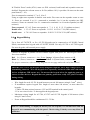
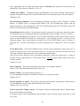
Double-Pole Zone wiring
This feature saves on wiring and doubles the zone quantity by using two wires instead of four,
for both TAMPER and ALARM indications.
Use always an EOL resistor; EOL prevents EMI and RFI interference
To activate Tamper Alarm, fit the zone with two EOL resistors, program ‘Enable Zone Tamper’
feature (address number 144, 145, 146, 147) and enable ‘EOL Resistor Zone’, entering the data
at address (140, 141, 142, 143).
To enable the EOL mode program the zone selected as EOL zone. For example: To enable zones
1, 2, 3 as EOL zones; in address 144; program 1, 2, 3 removed.
Any EOL zone will report Tamper alarm in case of zone shorting (if it has been EOL
programmed). To enable Tamper zone as 24H zone refer to address 075/1.
Upon Tamper alarm, a ‘t’ displayed, followed by the zone number. To disable Tamper alarm,
hold down key ‘9’. To display Tamper zone history, hold down key ‘0’ then key ’3’.
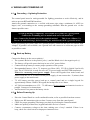
Use PIR, other sensor or Siren box alarm device that contains two separate switches or relay
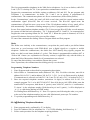
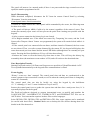
contacts: One for Alarm and one for Tamper. Connect each contact to a different EOL resistor.
Alarm contact connected in series with 2.2K and Tamper contact with 4.7K resistors. Both
resistors supplied with each system.
Figure 1: Double-Zone Wiring to EYS II PIR
11
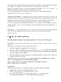
Some countries are used to different double-pole wiring as shown in figure 1A. For this wiring,
follow the drawing. European double-pole wiring requires 1.5K resistors (1.5K resistors not
supplied).
Figure 1A: European Double -Pole wiring drawing
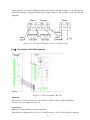
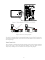
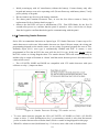
2.2 Connection of AV-816 Expander
Figure 2: Zone Expander Wiring
Mounting
Place the AV-816 board on the left side of the AV-2016 board as the drawing shows.
Use two screws to tighten the AV-816.
Connection
Make sure power and battery are disconnected.
Plug the wires connector of AV-816 to J1 socket at the AV-2016, refer to figure 2 drawing.
12
Zone Wiring Mode
Via programming, select either End-Of-Line (EOL) Resistor Protection, or non-EOL mode.
If EOL mode selected, install EOL Resistor (2.2K/0.25 or 0.5W) inside the detection device (e.g.
PIR, Magnetic Switch).
To enable EOL mode programming and resistors required.
To enable the Tamper Alarm of each zone, refer to the programming table and set the required
zone by programming address number 144, 145, 146, 147.
Wiring details are available in the AV-2016 manual, see Double-Zone wiring chapter.
Programming
Program the ‘Zone in Use’ feature for the required zones (address 102 and 103). By default,
program zones 1-16 set as ‘Zone in Use’.
2.3 AV-2055, 2088D Wiring
The AV-2088D contains eight zone terminals. Via programming, the panel becomes 16 zones,
when zone doubling used. Adding the AV-208 the panel expand to 32 zone. Refer to figure 3.
AV-2088D is compatible with AV-701, AV-702.
Figure 3: Zone Wiring AV-2055D, AV-2088D
AV-2055D: Default is five zones. To expand to 13 zones add the AV-208 expander board (not
supplied). Zones on the expander counted zone 6 to zone 13. In ABS box insert the AV-208 in
the left side of the box (grooves to fit), in metal box use the four supplied spacers).
13
In "Double Zones" mode (074-8, must use EOL resistors) both board and expander zones are
doubled. Program the relevant zones as In Use (address 101), it provides 10 zones on the main
panel board (1 - 10).
Zone 6 connected to terminal 1, 7 to 2, 10 to 5.
Using an eight-zone expander in double zone mode: First zone on the expander count as zone
11. Zones are counted 11 to 18 - connected to terminals 9 to 16 on the expander (use 2K2
resistors). Zones are counted 19 to 26 - connected to terminals 9 to 16 on the expander (use 4K7
resistors).
Zones on panel: 1 2 3 4 5. Zones on expander: 6 7 8 9 10 11 12 13 (without resistors)
Double zone: 1 2 3 4 5. Zones on expander: 11 12 13 14 15 16 17 18 (2K2 resistor)
Double zone: 6 7 8 9 10. Zones on expander: 19 20 21 22 23 24 25 26 (4K7 resistor)
2.4 Keypad Wiring
Up to four AV-701TS/TI, or five AV-702 Keypads can be connected to AV-2016D Control
Panels, maximum three keypad with AV-2055D, 2088D. Use only AV-701 or AV-702 keypad.
For more keypads, add external power supply.
Important: Consider adding a power supply when using more than max. keypads
Connect all keypads in parallel. Do not connect keypad with power on. Each keypad contains
four wires terminal:
Red (+) Power, connect to + Aux. Power Orange System Data, connect to OR
Black (-) Power, connect to - Aux. Power Yellow System Strobe, connect to YE
For proper connection, refer to wiring diagrams on next page and at the end of the manual.
IMPORTANT! Never run Keypad wires alongside telephone wires, high voltage wires, or
transmitting antennae. Wire the keypad wires separately and not in same cable with other
devices (telephone, PIR sensor etc.). Do not use the keypad wires for supplying power to
sensors or other devices. Keypads have no polarity protection; verify 12V power carefully
during wiring.
Wire length for each AV-701 keypad better not exceed 100 meters (using 0.5 mm2 wires).
If installation requires keypad wire length of more than 100 meters, or more than five
keypads:
1. Add a 470-ohm resistor between +12V and YE terminal in the control panel
2. Use two wires for the –V that supplies the keypad power
Maximum wiring length for AV-706, AV-707 and AV-702 keypads is 200 meters (when
using 0.5 mm2 wires).
Power at Keypad should be a minimum of 11.5 Volts.
Note: If a non-blinking ‘8’ displayed and keys do not respond, it is an indication that the
keypad is not communicating with the panel. Check wiring. Polarity error may blow the
panel fuse.
14
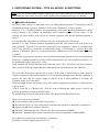
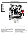
D34
F10
SIR1 AND SIR2 FUSES+
C16
R43
+
1.25A
Q4 C60
+
+
C14
C13+
D32
++
D10
F11
C15
C17
Q5
R42
1.25A D33
+
C12
D1
C18 R74
+
+
R73
R39
R45
D5
R46
D3
D2
-BATTERY
R44
+BATTERY
Keypad Power
AC
R94
SIR1
C19
D16
C11
+
R52
R98
R53
U3
-V
YE
R51
D21
RF4
VA6
R33
R102 R101
R62
VA5
RN1
OR
TM1
D17
D14
R36
R60
VA8
+12V
EOL Resistor
R37
D15
VA2
KEY
TMP
Tamper Sw (Optional)
U7
Q1
D25
R99 R100
SIR2
-12V
R59
R97
CB E
R93
SIR-
OR
YE
+12V
R40
VA1
AC
R41
D19
D9
BAT. FUSE
D18
D20
D4
AUX 12V FUSE
U13
R24
R22
R26
R20
R35
R34
F3
F7
K.PAD 12V FUSE
VA9
1.25A
R1
R2
R3
R4
2
3
4
-V
C10
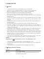
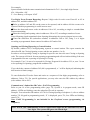
Back side of AV-701TIP keypad
++
VA3
1.25A
J1
+12V -12V 1
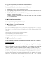
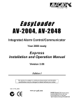
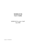
MUST CONCT-V TO AV-816
Keypad's Tamper Sw' connected to zone No. 1
Figure 4: Wiring Keypad AV-701TS/TI, AV-701TIP
Panel
Panel
AV-GAD
ARMED
STATUS
AV-GAD
EASYLOADER AV-701
SHUNT
ZONE
DISPLAY
FIRE
Siren
1
Delay
Delete
4
Chime
Test
7
Program
*
Shunt
ARMED
STATUS
AV-GAD
EASYLOADER AV-701
SHUNT
ZONE
DISPLAY
FIRE
2
Status
3
Siren
1
5
Telephone
6
Delay
Delete
4
Chime
8
Reset
9
Test
7
Program
*
Shunt
Shunt
Display
0
#
ARMED
STATUS
AV-GAD
EASYLOADER AV-701
SHUNT
ZONE
DISPLAY
FIRE
2
Status
3
Siren
1
5
Telephone
6
Delay
Delete
4
Chime
8
Reset
9
Test
7
Program
*
Shunt
Shunt
Display
0
#
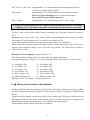
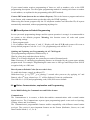
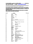
Wrong Wiring
ARMED
STATUS
EASYLOADER AV-701
SHUNT
ZONE
DISPLAY
FIRE
2
Status
3
Siren
1
2
Status
3
5
Telephone
6
Delay
Delete
4
Chime
5
Telephone
6
8
Reset
9
Test
7
Program
8
Reset
9
*
Shunt
0
Shunt
Display
0
#
Shunt
Display
#
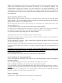
Correct Wiring
Figure 5: Best way wiring keypads
For trouble free operation follow the recommended wiring as shown in figure 5 drawing, wire
each keypad to the panel directly, avoid to run wires from one keypad to next (as shown the on
the ‘Wrong Wiring’).
Keypad Tamper Switch
The AV-701TIP, AV-702TP keypads (keypad with tamper switch) contain a Tamper switch that
activates upon trying to remove the keypad after installed. Connect the Tamper switch to
Tamper, Day or 24H type zone. For connection, refer to keypad’s wiring diagram.
15
3. ALARM OUTPUTS
3.1 Sirens
Control panel enables driving of two separate speaker sirens or bells.
Speaker siren issues a multiple-tone alarm. Use 14W, 8 to 16 ohm speaker siren.
Bell mode (sounder that works on 12V DC) is available via programming.
Enclose the outdoor siren in a metal box tamper-switch protection.
Protect siren or bell box with tamper-switch connected to a 24H zone.
The control unit contains two siren outputs, for internal and external siren, individually
protected by fuses.
If Siren mode selected, use speaker type siren with a minimum power of 15W, 8 Ohms
impedance. Enclose the outdoor siren in a metal housing, with anti-tamper switch
protection.
In Siren mode, install only speaker-type sirens, which DO NOT contain sound driver or
electronic modules.
The alarm issued by the Siren (not Bell mode) differs according to the type of zone.
‘Bell Mode‘ is default-set at factory. Bell converts Siren outputs into 13.6 VDC outputs (no
sound is issued). Bell mode is applicable for driving self-powered sirens or bells, or
combined sirens and strobes.
In Bell mode, connect only Bell or sirens that contain a 12V sound electronic driver
module. Bella sirens are compatible and feature high sound level at very low current use.
Self-contained Bell mode is programmable (address 071). This mode allows connection of
Bells or Sirens that require 12V at ideal and 0V during alarm. The Bell output voltage
regulated at about 13.6V. For self-contained siren, it is recommended to use Av-Gad Bella 2
or Bella 3 siren, both with Xenon strobe light.
Some Piezo siren generate high voltage spikes that may reset the panel, in such cases
connect the + siren to +Battery (battery + lug) and – siren to –SIR in the panel.
Warning!
Output power for each siren should not exceed 0.7A (total Bell output is 1.4A).
Contact manufacturer's consultant before connecting higher power loads.
To connect self-contained sirens, Bells, and inner-oscillating sirens, refer to address 072;
see Bell mode.
Contact manufacturer's consultant before connecting higher power loads.
3.2 Remote Indication Terminals
Indication
Application
ON
OUT 1 (A1)
(-V) on closing (Arming)
Programmable. (-V) during alarm from the programmed zone or
event (tamper alarm or panic)
16
OUT 2 (A2) AV-2016 only Programmable. (-V) during alarm from the programmed zone or
event (reset, tamper alarm or panic)
SLO Output
Programmable. (-V) during alarm from the programmed zone
Resets only upon disarming (SLO is a non-timed output).
Most useful for strobe light connection.
SLO 1 Output
Programmable. (-V) during Smoke reset or Code 7 entry
Warning: The remote indications are capable of driving maximum 300 mA, overloading
or applying +12V to the remote indications is dangerous and not assured by warranty
To drive a low current Strobe Light (Xenon) consuming up to 300 mA, connect the strobe to
SLO.
Beginning with version 2.08, a new feature enables programming the listed outputs to supply
float output (0V) during alarm and -V at ideal. Refer to address 073-8.
In case other features selected for the same output, this feature is not applicable.
When connected a relay the remote indication, connect a diode must to the relay coil in reserve
polarity to the supplied voltage, or use AV-01/02 relay module. For LED driving, connect a
2.2K resistor in series.
Hardware Tests for Outputs (starting version 2.17)
This feature enables testing of devices connected to the remote indications.
In programming mode, using 200 + 30 to 43 commands (SLO1 exist only in AV-2016 panels):
30 - On Output: ON
31 - On Output: OFF
32 - A1 Output: ON
33 - A1 Output: OFF
34 - A2 Output: ON
35 - A2 Output: OFF
36 - SLO Output: ON
37 - SLO Output: OFF
38 - SLO1 Output: ON
39 - SLO1 Output: OFF
40 - SPARE Output: ON
41 - SPARE Output: OFF
PRO only: 42/43 LCD display - Display pattern test
3.3 Wiring and Connection of Relay Module
The Relay Module enables connection of EasyLoader 2000 Series panels to most types of Bells
and self-contained internal battery Bells or Sirens (the term ‘Bell’ will apply to both Bells and
Sirens).
Trigger the Relay Module via the siren output of the control panel. The power which drives the
Bell supplied from the Aux. Power of the control panel, or from an external power supply in case
the Bell requires higher current than the 0.7A supplied by the control panel.
Full installation details enclosed with the relay module.
17
4. WIRING AND POWERING UP
4.1 Grounding – Lightning Protection
The control panel must be earth grounded for lighting protection to work effectively, and in
order to prevent RFI and EMI interfaces.
Attach the ground connection to a verified cold-water pipe using a minimum 16 AWG (or
larger) wire, or according to the country-grounding standards. Run the ground wire via the
shortest possible route.
System grounding is compulsory. For trouble free system, use a good ground.
Connect the Grounding wire to main board and to the metal box.
Note: Connect the Ground wire to the terminal marked
. This is not a Minus (-V).
Beware of static discharge; before handling the main board touch a grounded metal.
Before grounding the system, make sure ground properly connected and does not transfer high
voltages. If ground is not available, run a ground wire and connect to a cold water pipe as close
as possible to earth.
4.2 Back-up Battery
Connect the Battery in the correct polarity!
The system's Red wire is the positive pole (+) and the Black wire is the negative pole (-).
The battery will provide power back-up in case of AC power failure.
Connect back-up battery to ensure proper operation of the system.
Recommended battery: 6.0 to 7.2 Amperes per Hour (AH), 12V SLA (Sealed Lead Acid)
type. The AV-2016 box is ready for extra AV-21 power supply and 5003TER transformer.
Notice for connecting extra power supply: Power the keypads from main board and
sensors from the AV-21 or other external power supply, do not connect the –V (minus) from
power supply to the main board.
7.2 AH battery provides power back-up to control panel and to a single keypad for
approximately 8 hours. With LCD keypad, the backup time is to 6 hours.
AV-2016 accommodates two 12V - 7.2 AH battery. Do not connect two batteries in series or
parallel. Contact us for instructions.
An Electronic Fuse protects the battery circuit.
4.3 Before Powering Up
Place the Control Panel in a well-ventilated location, as far as possible from heat sources.
High power RF transmitters place at least 2 meters away from the control panel.
Check for proper grounding. Discharge your body by touching the Ground terminal.
Make sure polarity of detectors, keypads and other devices is correct.
Connect a momentary voltage to the siren; making sure a ‘beep’ sounded. If there is no
beep, check for a short circuit or improper connected wires.
18
Initial powering-up with AC transformer (without the battery). Connect battery only after
keypad and sensors seem to be operating well. (Do not Power-up with battery alone.) Verify
power polarity of keypads.
Do not connect any devices to the battery terminals.
The alarm panel contains Electronic Fuse, in case the fuse blows return to factory for
replacement. Refer to further details at page 9.
Observe the dial LED self test at initialization (STI) - Dial LED blinks for the first 50
seconds after power on, confirms that the panel is operative. Also, wait for the six beeps
from the keypad to confirm that the keypad is communicating with the panel.
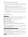
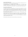
4.4 Connecting Smoke Detectors
Series 2016 accommodate Ionization or Optical type 12V Smoke Detectors. Connect up to five
smoke detectors to each zone. Most smoke detectors are Open Collector output, the wiring and
programming depends on the smoke sensor you are using, on general program the zone as Fire,
Normally Open (N.O.) zone type is automatically enabled and EOL. It means; a zone
programmed as Fire (but no EOL) the zone will also be N.O. type. In this case, do not connect
the EOL resistor as wiring diagram show. The smoke detector LED will remain constantly lit
and the relay or output will remain in ‘Alarm’ until the smoke detector power is disconnected for
a short while (reset).
The AV-2055D, 2088D and 2016D are compatible with 12V smoke detectors with open
collector or relay (-) output on alarm.
Figure 6: Smoke Detector Wiring (TF smoke series)
To reset smoke detector program the SLO (AV-2055D, AV-2088D) or SLO1 (AV-2016D)
output to drive -V while holding-down key 9 (a momentary switch or relay that disconnects
power to smoke detector after a smoke alarm). Refer to smoke wiring diagram on this page.
When Fire Alarm occurred, hold-down key ‘9’ for reset, enter valid code to disable alarm.
19
4.5 Telephone System Dialing
It’s recommended to connect the control panel to an independent telephone line, if a device is in
parallel with the alarm panel, this may grab the call first (like a message answer/fax) during
remote up and download.
Do not connect fax or answering machine in parallel on the same telephone line.
In case of alarm the dialer dials to the programmed numbers, siren sound or voice message (if
SVM-40 connected) transmitted to the telephone. The voice module will apply spoken message
over the telephone upon alarm.
Default dialing mode is DTMF. If PULSE dial selected, the default is European Make/Break rate
of 40/60 milliseconds (in Pulse dialing). The Make/Break rate is programmable.
Dialing mode is programmable (refer to programming sheet addresses 088 and 089).
Connect the telephone line to ‘TEL-LINE’ terminal, if handsets connected to same line connect
them to ‘PHONES’, when system attempt to dial the ‘PHONES’ disconnected. Do not connect
to ISDN or other digital telephone system. Most ISDN converters have an Analog line; connect
the Analog line of the ISDN the TEL-LINE terminal. Option: To protect your line add the TeleSpy, it is a 24H telephone line monitor separate module. Note: To perform telephone line test
enable Dial Tone detection at address 083.
For AUSTEL installations: At address 074 enter 8, at address 087 enter 2 (maximum), don’t
connect any phones in parallel with TEL-LINE terminal. Software Dial Tone telephone monitor
is included, refer to address 094, 076 options 5,6. Dialing problems may occur when system
telephone line is connected to Telstra Duet system or similar.
4.6 SVM – Voice module
The SVM-40 and SVM-60 speech modules allow the recording and playback of two messages,
with optional playback through an external speaker (not included). SVM-40 message duration is
40 seconds; SVM-60 message duration is 60 seconds. The SVM contains an on board
microphone.
The SVM is a high technology device, electronically stores messages with or without power.
The SVM is as a digital message source in Series 2000 Alarm Control Panels, telephone dialers
or in other applications. The SVM supplied audio is capable to drive audio amplifier, message
center, automatic dialer or other device.
When connected to Series 2000 Alarm Control Panels, program the SVM option (at
programming table 072-7). Follow the wiring procedures (included in SVM manual) simulate
alarm, the panel will dial first the Communicator telephone number (telephone number 2 and 3),
then dial to other programmed numbers.
After dialing, the panel will trig the SVM to send the recorded message. If address 071 (1) is
programmed Telephone 1 is erased within arming and disarming.
20
4.7 Remote Key and Wireless Arming & Disarming
The AV-2055D, 2088D, 2016D enables Arming/Disarming by remote momentary or latch
key-switch (as programmed in address 071), which is connected to terminals ‘KE’ and ‘Aux. Power’.
When using remote key-switch, wire length should not exceed 10 meters.
A Momentary pulse (momentary trig) between ‘KEY’ and ‘-V’ terminals will Arm and
Disarm the control panel. (Before arming close ‘instant’ and ‘24H’ zones)
System reverts to previous status with next momentary pulse. (Refer to AV-2016 Wiring
Diagram.)
Arming by key will cause a long beep at the keypad if "Enable two siren beeps at disarm"
(073 - 6) is programmed.
For Arming/Disarming via Wireless Radio Remote, connect receiver's relay to ‘KE’ and
‘- Aux. Power’ terminals. Verify the receiver relay mode, momentary, or latch, and set
system accordingly.
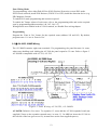
4.8 Remote Access via DTMF
General Description
Remote DTMF enables remote control of the alarm panel from a DTMF phone, this unique
feature provides Home Automation function and other functions as detailed below.
DTMF commands are possible when the panel call your phone, or by calling the panel. The
DTMF remote control functions:
Check the status of the control panel (Armed/Disarm, Alarm in progress)
Arm or disarm the control panel
Bypass zones or clear all bypassed zones
Stop the dialer report during alarm
Momentary activate A1 (alarm) output for three seconds
First Alarm indication - by a number of beeps per zone, special tune for Panic alarm
The same options are available when a call received from the control panel during an alarm
condition.
To enable the DTMF control program address 076/4 “Enable remote access by telephone”, and
076 - 2 “Enable A1 activation by telephone”.
In AV-2016DP, only User 01 (master) allowed to Arm, Disarm and Bypass zones, all other
functions are accessible to all users.
Keypad online conformation and DTMF functions history
When the control panel detects the first DTMF key, five short beeps at the keypads. The keypad
activation shows the user at the remote site that a DTMF connection takes place (in case of
mistaken connection or similar).
During the remote access the keypad display 'd' and all LEDs blink fast from time to time.
At call ends, three short beeps sound at the keypads. When the user code is in process, the
keypad display shows a line for each code number entry (disclose the code), then each DTMF
number pressed show the received number.
History log: Each call, confirmed by a valid user code, Arming/Disarming and other events
made by the remote DTMF phone are recorded in the event history.
21
"Last users" history will display 'ut' for "user "telephone, followed by the User number.
Notes: 1. The keypad buzzer or other loud sounds may jam your DTMF entries, in case the
keypad is close to your DTMF telephone, during testing disable the buzzer.
2. When entering the DTMF commands wait for “quit” period, if entering commands
during the system confirmation tunes, or other tunes the panel may miss the DTMF
entries.
The panel calls the user during alarm
When the control panel calls the user during alarm, it will first generate the siren sound for about
30 seconds (to shorten this feature at address 085 “Tel. Message Time”, to 30, as default is 50
seconds). The siren sound will stop ten (10) seconds before the end of the call and a greeting
tune will be sounded, after the greeting tune enter your code followed by #.
To stop the dialer enter 6#, to get panel status enter 7#, to disarm the panel enter 2#. Press 9# to
end the process.
The control panel will answer the call after the number of rings programmed at address 091 (or
following the “bypass answering machine" procedure).
Commands
Each command must be followed by the '#' key (Enter) in the remote phone. The control panel
waits 4 seconds between the keys typed. When this time expires, previous keys input will be
discarded.
The key '*' cancels previous input. It is recommended to start with "learn" function [8X #] to
identify the various confirmation tune.
The commands:
[0 X #] - Bypass zone (# is the Enter key)
X is Bypassed zone 1 to 8
To clear all bypassed zone: 0 9 #
The zone bypass command is valid only when the system is in Disarm position and not in Alarm
position.
[1 #] - Arm the control panel. The control panel arms even with open zones. After the arming,
a confirmation tune followed by an "armed" tune heard ("Armed" tune: Short beep followed by a
long tone.).
The user can wait a few seconds to be sure that no alarm caused by open zones. In this case, an
Alarm tune (siren sound) sound.
[2 #] - Disarm control panel. When control panel disarmed A confirmation tune followed by a
"disarmed" tune heard ("Disarmed" tune: Five short beeps).
[31 #] - Activates A1 output for 3 seconds (enabled by programming 076-2)
[33 #] - Activates SLO output for 5 seconds, keypad sounds 7 short beeps (enabled if SLO is
not used with zones alarm events or for Chime activation)
[6 #] - Stops dialer. The dialer will stop calling the programmed telephone numbers. This will
affect only the current dialing process. A new alarm will re-start the dialer.
22
Note that if the user answered a call from the panel or called the panel during a dialing period
without Arming/Disarming/Stopping the dialer, the dialer will restart the cycle from the
beginning.
[7 #] - Check control panel status. The control panel will answer with an Armed or Disarmed
tune followed by an Alarm tune if it is in an alarm condition.
[7 and 7 #] - First Alarm Zone Report, beeps count for the zone number. Report user the first
zone that caused alarm. Arming or Disarming clears the First alarm zone reported by DTMF.
Zones 1 - 10: 1 to 10 short high tones
Zones 11 - 19: One long low beep for 10 followed by 1 to 9 short high beeps.
For example, zone 14: Reported as one long - low beep followed by four (4) short beeps.
Zone 20: Two long - low beeps.
Zones 21 - 24: Two long - low beeps followed by 1 - 4 short high beeps.
[8X #] - Learn function tunes. Using this command, the user can become familiar with the
various sounds used by the control panel in the remote access procedure. Further details find in
the dedicated paragraph. (X - The required sound).
[9 #] - End call. The control panel will sound a confirmation tune and will hang up.
SECTION III: AV-701 & AV-702 DIGITAL KEYPAD
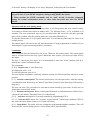
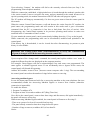
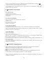
1.1 Standard Keypad Functions
AV-GAD
ARMED
STATUS
EASYLOADER AV-701
SHUNT
ZONE
DISPLAY
FIRE
Siren
1
Shunt
Display
2
Delay
Delete
4
Chime
5
Test
7
Program
8
*
Shunt
0
Figure 7: AV-701 Keypad Layout
23
Status
3
6
Telephone
Reset
9
#
Common Terms in this Manual
‘SHUNT‘ and ‘BYPASS’ are interchangeable terms
Program Mode - Enables features programming, ‘P’ is displayed, alarm is disabled
Use Mode – System disarmed and not in alarm or program mode
AV-701TS, AV-701TI or AV-702 are identical
Standard Keypad functions are accessed by pressing keys (short press). The 1 to 0 keys used
for Arming/Disarming (ON/OFF), Zone Shunt (Bypass), and other programming
functions.
A short beep confirms each key press.
A short press on keypad key accesses the following special functions:
Chime
5
Instant Arming, by pressing key ‘5’ (requires programming).
Shunt
0
Zone Bypass, by pressing key ‘0,’ followed by entering the Zone numbers 01 to 32.
Shunt
0
Zone Bypass Via Code (requires programming, see address 071).
Press key ‘0’, while 4 LEDs are blinking, enter user code No. 1; When the 2 left- most LEDs are
blinking, enter zone number(s) (2 digits format) to be bypassed, four LEDs stop blinking,
‘Shunt’ LED remains on to confirm zone bypass. Within 20 seconds, enter your user code to
Arm the system. Note: Zone Bypass via Code is standard in AV-2016DP.
0
0 Group Bypass, press 0 and two presses on key ‘0.’ Groupthen
Bypass is operative only if system armed within 60 seconds from the entry of this feature.
Yellow LED will flash and ‘h’ (Home) displayed for 1 second in confirmation.
Shunt
0
Shunt
0
Shunt
Shunt
0 . Press key ‘0’ twice for Group Bypass. Operative only if system is
and
Armed within 20 seconds after entry of this feature. Yellow LED will flash; ‘h’ (Home)
displayed for 1 second in confirmation.
Starting version 2.13 PRO only: To activate Group Bypass II press key ‘0’ three times. To
activate both group bypass groups, press 0 then 88.
From version 2.04 and on, when Group Bypass is selected, the buzzer and LEDs react as
follows:
Shunt LED stops blinking 8 seconds after Arming, (prevents LED light from disturbing
sleepers near the keypad)
There is no exit/entry delay-warning buzzer, and keys beep at the keypad.
There are no ‘beeps’ at the keypad until an alarm occurs, or until Group Bypass is canceled.
When the keypad LEDs are turned off after Arming (requires programming), touching the
keypad will turn them on for 5 seconds.
Shunt
Group Bypass with code (requires programming). Press key ‘0.’ While 4 LEDs are blinking,
enter valid user code.
24
When only two left most LEDs are blinking, press ‘0’ key again, ‘h’ will be displayed and
‘Shunt’ LED will remain blinking to confirm Group Bypass. Enter your user code to Arm
system. Note: Complete Group Bypass within 180 seconds or Group Bypass is voided.
1.2 Hold-Down Functions
Holding down the key for approximately 2 seconds accesses hold-down functions
Hold down functions are confirmed by a long beep
Hold-Down Functions:
Siren
1
Key 1 SIREN TEST
Shunt
Display
2
Key 2 SHUNT DISPLAY
Displays shunted zone(s).
Status
3
Key 3 STATUS DISPLAY
Displays troubled or malfunctioning zone(s).
Delay
Delete
4
Key 4 DELAY DELETE (INSTANT PROTECTION)
Cancels Entry delays in zones selected as ‘Delayed’ zones. All zones become
Instant.
‘d’ is displayed in confirmation. Instant Protection becomes effective only if System
is Armed within 20 seconds following hold-down of key 4.
Chime
5
Telephone
6
Key 5 DOOR CHIME
Enables Chime when opening zone. Door Chime operates on Chime-programmed
zones. Hold-down key 5 enables and disables the function.
Chime mode is confirmed by ‘c’ display on keypad.
Key 6 DIALER TEST & FOLLOW-ME PROGRAMMING
Test is performed in ‘DISARMED’ mode.
Function
Displays Programmed Follow
Me Telephone Number Without
Dialing
Follow Me telephone number
programming
Programmed Telephone number
Verification (Display and Dial 4
telephone numbers)
25
Via AV-701, 702 Keypad
Hold-down key [6]
Hold-down [6] then holddown [7], number is
displayed
Display programmed telephone numbers without dialing: Within few seconds, ‘c’ will appear on
the display, followed by the (programmed) ‘Follow Me’ telephone number.
When programming telephone numbers that requires an inter-digit delay (‘Pause’) during
dialing; Hold-Down key [0], a momentary ‘P’ displayed (Delay duration is 3 seconds).
The ‘Follow-Me’ number is displayed, or displayed and dialed, followed by display-and-dial of
up to three additional telephone numbers.
6
Telephone
1
and Siren
. Address 092 enables ‘Answer Now‘ feature, the system answers
remote computer after one ring. This feature is important if the control panel programmed not to
answer incoming calls (programming of 21 rings or greater at address 091). To enable ‘Answer
Now’ feature program 01 at address 092.
Hold-down key 6 and then key 1, before the computer and modem connect (dial) the control
panel. The panel will acknowledge the command with two beeps and display an ‘A.’ The feature
remains active for 5 minutes after entered, enabling to remotely program (from remote
computer) the panel.
Other possibility to connect to a system connected on same line with a fax or answering machine
is to use the “Answer machine bypass” feature.
Test
7
Key 7 FAULT FIND
Fault Find enables testing of all detection devices.
Fault Find mode is accessible only during 15 seconds following System Disarm.
24H, Fire or Panic alarm will stop Fault Find mode.
Hold down key 7, confirmed by ‘F’ on Keypad display.
Open and close each zone to test the zone regularity. A one-second beep confirms detection
of zone opening. Three beeps indicate zone closing.
Quit Fault Find mode by Arming the system.
Program
8
Reset
9
1.
2.
3
4.
5.
Key 8 PROGRAM
Key 8 accesses ‘Program’ mode and user code programming (changing).
Key 9 RESET. ‘Reset’ performs the following functions:
Cancels last Keypad entry
Stops the communication test (triggered by hold-down key 6)
Activates output 2 for resetting the Smoke Detector (requires programming)
Resets Day Zone Alarm at Keypad
Exits Programming mode (features, telephone numbers, etc.). For
PRO and LED (version 3.04 and higher) panels enter 999 to exit
programming mode
26
Key Zero Hold-Down functions
0 Key 0 Concise Alarm History: Hold down key ‘0’ to display the last alarm
1.
sequence.
Shunt
0 and
0 Detailed Events History (requires programming): Hold down key
2.
‘0’ and again hold down key ‘0’ to display up to 36 events, including: System opening and
closing by user number, opening or closing time, alarming zone and AC fail.
By holding-down key Shunt 0 twice, three LEDs start blinking, to indicate a special operation
mode. The events are displayed from the most recent event to the oldest.
At AV-701/2 keypad the events displayed as following:
XX - Event number (from 01 to 36), then HH_MM (Hour and Minutes) Event Time, Event
(alarm or opening/closing).
Translate the display as following:
‘u’ (user number 1 to 16), ‘o’ or ‘c’ - opening or closing, Zone causing alarm will blink twice
tX - Tamper alarm from zone causing the alarm (X), H - Panic Keypad Alarm
Note: 3 lines () indicate power fail. An AC fail event displayed during history events.
Shunt
Shunt
Event
AV-701, 702 display
Time set
'tu'
Date set
'du'
Installer programming
'IP'
User programming
'UP'
Factory defaults
'Fd'
Communication (to CS) failure 'CF'
Panic from Panic zone
‘Hzz’ (zz = zone number)
Keypad locked (code error)
'PE'
Low Battery
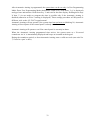
'Lb'
Table 1: Events as displayed at AV -2016D
Events display example at AV-701, 702:
- Sign then long beep
indicates end of History
Zone no. blinks twice
01 2 2 _ 2 4 u 1 o
02 2 3 _ 0 5 7 7
03 2 3 _ 3 5 H H
04 0 0 _ 0 8 u 1 c -
Display
Event 01
Time
User 1
Opening
Event 2 Time Alarm Zone 7 Event 3 Time Alarm Zone H Event 4 Time User 1 Closing
Figure 8: Events Log as Displayed at Keypad
During zone number display, keypad display blinks twice to indicate the zone number.
Browsing through Events History
Keys used for browsing:
Shunt
Display 2
Skip forward to next event
27
Display current event again
Chime
5
Program
8 Skip backward to previous event
Cancel History Event Mode and exit
Upon display of last event, if an attempt is made to move forward (key 2), a blank sign ‘-‘ is
displayed, along with a warning beep indicating that this is the last event. Press key 8 may to
move backward. If no key is pressed, Event History stops and system returns to Use mode.
When starting History Events mode the events are displayed from the beginning to end without
any break, until any browsing key is pressed.
Reset
9
During History Events, browsing system will respond only to alarm or panic, Arming
denied.
Alarm or Panic during History Event mode will quit this mode and system will set to Use
Mode (normal operation mode).
For easier detailed alarm history, use the downloaded from panel to remote computer. History
queue log of up to 99 events are displayed at the keypad and in the EasyLoad PC software.
1
0 and
4.
Display and Setting of System Time: Hold down key ‘0’ and then
hold-down key ‘1,’ 3 LEDs will blink. Wait for the display of system time in 4-digit format.
To set new time, hold down key ‘0’ and then hold down key ‘1.’ Do not wait for time display;
enter the new time in 24-hour format. The local clock time is not stored in system memory;
adjust clock after power-up. After powering-up system, time is reset to 00:00, ‘h’ will be
displayed to remind user to set time; ‘h’ will disappear after setting the time. If Auto-Arming
enabled the clock setting is from user Programming mode only, refer to Auto-Arming section.
Shunt
Siren
Shunt
2
Shunt 0
5.
and Display
Display and Setting of System Date: Hold down key ‘0’ and then
hold-down key ‘2’; 3 LEDs will blink. Enter date: ‘dd mm yy.’ The up and download PC
software displays time and date, along with event history.
The local date is stored in system memory; adjust date after long power-fail.
Years 78 through 99 translated as 1978 to 1999
Years 00 through 77 translated as 2000 to 2077
3
0 and Status Concise History of Tampered Zones: Hold down key ‘0’ and then
5.
hold down key ‘3’ to display the Tampered zone alarm sequence.
New alarm will create a new history event instead of old one.
Shunt
Shunt
0
Delay
Delete
4
6.
and
Reset Events Memory (history): Hold down key ‘0’ and then hold
down key ‘4’ to clear all events from memory. Starting version 2.09, cannot erase the history log
(former command ‘0’ + ‘4’).
Instead, during the installer-programming mode, clear history by command 200+04.
28
5
0 and
7.
Display Last 2 Users: Hold down key ‘0’ and then hold down key 5
to display user number and System opening or closing time.
‘o’ is displayed for Opening (Disarming); ‘c’ is displayed for Closing (Arming).
Shunt
Chime
0 Press (not hold-down) and press
8.
cancel all Bypassed Zones.
Shunt
*
Keypad Panic
Reset
9
(not hold-down), will display ‘-’ to
#
Keys PANIC BUTTON
Holding down * and # keys will trigger Panic alarm. H will be displayed (zone ‘H’).
To cancel Hold-Down function accessed by keys [0], [6] and [7]; Hold-Down key 9 (Reset).
To quit zero hold-down functions, hold-down ‘9
1.3 Keypad Sounder
The Keypad sounder enhances the use of system operation and serves as a local alarm device
(requires programming).
The sounder emits sounds in the following instances:
OPERATION
Pressing of any key
SOUNDER RESPONSE
Short confirmation beep
Power up
Six beeps
Hold-down functions
Long confirmation beep
Faulty programming input
Long beep (+ ‘E’ display)
Delayed Zone triggering
Three long beeps
Exit delay starting (if programmed)
Warning beeps until the delay is over
Completion of Arm/Disarm
programming code
Programming Telephone numbers
One long confirmation beep
Completion of address programming
Two confirmation beeps
Pressing ‘Code 7’ for driving door
opening
Arming of System with Instant, Fire or
24H troubled zones
Feature programming
Seven confirmation beeps
Follow-Me number programming
Two confirmation beeps
During alarm (requires programming)
Intermittent beep until alarm reset
Two confirmation beeps
Five warning beeps + troubled zone
display
Two confirmation beeps
29
1.4 LED Indicators
AV-701 and AV-702 Keypads: Four LEDs provide visual indication of System status, as well as
confirmation of various modes.
Keypad LED’s indication
Armed Led-Red
Off
Blink slowly
ON steady
Blink fast
AV-2016
System Disarmed
An alarm is triggered
System Armed
Mode does not exist
AV-2016DP
All partitions Disarmed
At least one partition is armed
All partitions are ARMED
Alarm triggered in partition/s
Status LED-Green
Off
Blink slowly
ON steady
Blink fast
AV-2016
System Disarmed
Some zones are open
All zones OK
Some zones have been tampered
AV-2016DP
Some partitions are Armed
Some zones are open
All zones OK
Some zones have been tampered
Shunt LED-Orange
ON steady
Blink slowly
Blink slowly
AV-2016
AV-2016DP
Some zones are bypassed
Some zones are bypassed
Group bypass entered
Group bypass in some partition
8 seconds after Armed with 8 seconds after Armed with
Group Bypass
Group Bypass
Fire LED-Red
AV-2016
AV-2016DP
Warning before Fire alarm
Warning before Fire alarm
Blink slow
During and after Fire alarm
During and after Fire alarm
Blink fast
Note: Troubled Zones during alarm displayed at the Keypad.
Red ARMED/ALARM Indicator - Lights up when system is armed, and blinks after an
alarm is triggered at any zone. Blinking indicates alarm history in memory.
Green STATUS Indicator – The Green LED Blinks when zone/s are troubled and remains
lit as long as zones are clear, rapid blinking during Tamper alarm.
Yellow SHUNT (Bypass) Indicator - Lights up upon zone bypass.
(Note: may light automatically upon arming if Auto Bypass was programmed).
The indicator also lights up and blinks if a Group Bypass was entered by pressing ‘0’ twice.
Red FIRE (Trouble) Indicator - Rapid blinking when a Fire Zone is troubled.
Two LEDs Flashing (Left Most LEDs) - In user code programming mode, rapid blinking
indicates code or code index to be entered. In Installer programming mode, it indicates address
entry.
In Disarmed mode, the two left-most LEDs blinking + zone number display indicate 24H-alarm
mode.
30
Three LEDs Flashing - In Disarmed mode, rapid blinking indicates AC power failure.
AC power fail event is displayed in Events History as three lines . Starting version 2.11 the
LEDs will blink for six seconds every minute (energy saving).
In Armed mode, rapid blinking indicates system restored after AC Power Failure mode.
During programming Follow-Me Telephone Number, three flashing LEDs indicate to enter a
new telephone number.
Four LEDs Flashing - Upon holding-down key ‘8,’ the system is ready for code to be
entered. (Same LED indication when code is expected for Bypass via code.)
1.5 Keypad Digital Display (7-segment type)
The 7-segment display provides visual readout of system status. The display indicates zones in
alarm, troubled zones, bypassed zones, and also displays the following confirmation letters:
Display
A
CA
C
Description
Auto Arm
Up & Download
Communication
C
c
Communication
Chime
c
Closing
d
P
Delay Delete
or DTMF
Dial Delay
E
h
h
Error
Home
Hour
H
Hold-Up
o
Opening
L
Low Battery
P
t
Program
Tamper
Function
‘A’ confirms that auto arming starts within 30 sec’s
‘CA’ displayed after ‘Answer Now’ selected
Tests dialer, and displays telephone numbers upon
holding-down key 6
Flashing ‘C’ in display indicates telephone line trouble
Upon entering Chime mode via key 5, ‘c’ confirms
Chime mode
Indicates system closing (Arming) followed by user
number when events log is displayed
Upon holding-down key 4, to operate Delay Delete of
delayed and follower zones. Indicate DTMF mode too
When programming telephone numbers which require
an inter-digit delay (‘Pause‘) during dialing. (Delay
duration is 2 seconds.)
Indicates programming error
Indicates entering of Group Bypass
Displayed after power-up to remind installer to set the
system time; ‘h’ will be removed after time setting
(using keys 0 and 1).
Upon Panic triggering from Keypad, or upon
activation of any other panic switch connected to the
keypad
Indicates system opening (Disarming). Followed by
user number when events log is displayed
Low battery indicated upon system arming, or during
Disarmed mode
System is in programming mode
Indicates zone's Tamper alarm
31
U
u
Update
User
Arming Denied
or
AC Fail
Confirms programming updating
‘u’ (user) followed by user number when events log is
displayed and system is in user code programming
mode
displayed upon Arming attempt with non-delayed
(instant) zones in trouble.
displayed upon and after AC fail while system is
Armed or Disarmed
1.6 Arm and Disarm System via AV-701/702 Series Keypad
1. Make sure that all burglary zones are closed.
2. The green Status LED indicator will remain lit (not blinking) while all zones are closed.
3. Green indicator will blink when a zone is troubled. Press key 3 for display of troubled zone
on keypad. An open delayed zone (exit zone) will also cause indicator to blink.
(3 lines) indicated at arming of system if instant zones or 24-Hour zones are troubled
(blinking Green LED indicator followed by in display and 5 warning beeps); open zones
will then be displayed.
4. To bypass a zone, press key 0 (Bypass Key), followed by the zone number.
To bypass a pre-programmed group of zones (requires programming), press 0 (zero key)
twice (short press). AV-2016DP/2.09: Enter your code then press key 3.
5. Arming: Enter the Arm/Disarm code (No. 1 default code is 1,2,3,4), the Red Armed
indicator will light up. If any zone (not Delayed or Follower) is troubled, will be displayed
and system will remain Disarmed.
System Arming is disabled if Instant zone troubled.
6. For Instant Arming, press key 5 (if previously programmed). See address 071.
Red ‘Armed’ indicator should light up. The system is now armed.
7. Disarming: you may have to hold-down key 9 (reset) to clear any previous key presses, and
then enter arm/disarm code (or turn optional key-switch); the Red ‘Armed’ indicator will go
off.
Alarm history displayed upon disarming. If a 24H alarm occurs during Disarm mode Enter
Arm/Disarm code.
8. Keypad Keys Self Locking: In Armed and Disarmed mode, after six attempts to enter fault
code, the keys will not react to any key press. This prevents code learning or other code
break exigency. After a 30 seconds delay, the keys will revert to code entry mode. Each new
erroneous code will lock system for another 30 seconds.
9. Auto Arming
Programming the time for Automatic Arming:
- By Installer: Program (or display) the hours and minutes at address 016.
- By User: Enter to user programming mode. Hold down '8' ('A' is displayed); type hour and
minutes in 24 hours format. To display, hold down '8' and wait. To disable Automatic
Arming program 0000.
32
After Automatic Arming is programmed, the system time can be set only via User Programming
Mode: Enter User Programming Mode (hold-down 8 and 1234), hold down '1' ('t' is displayed)
and type hour and minutes. Hold down key '1' and wait for the time display. Holding down keys
'0' then '1' (in use mode) to program the time is possible only if the Automatic Arming is
disabled (otherwise an 'Error’ warning is displayed). Those settings procedure at PRO panels is
different; refer to the AV-706/7 keypad manual.
Automatic Arming will not operate if the system time has not been set (blinking 'h'). Automatic
Arming will not operate if the control panel is already armed.
Automatic Arming will operate even if the control panel is currently in alarm.
When the Automatic Arming programmed time arrives, the system starts at a 30-second
countdown. An 'A' is intermittently displayed and beeps are sounded at the keypad.
During the countdown period, to abort Automatic Arming enter a valid user code (not code No.
7, if used to ‘open’ a door).
33
SECTION IV: PROGRAMMING
1. SYSTEM CODES
Up to sixteen different Arm/Disarm codes and one installer (dealer) code are available; each code
consists of 1 to 6 digits.
Do not use ‘0’ as the first digit in a code.
Do not use ‘5’ as first digit in a code number if Instant Arming via key 5 was programmed.
User code must not start with the same numbers as the installer programming code (1994).
Do not use same codes or same first digit for different codes. For example if code No .1 is 1234,
programming code No. 2 cannot be 1256.
1. Default Arming and Disarming Code ‘1 2 3 4’ (Code No. 1) - Use ‘1234’ as Arming
Code (also called Owner Code). Use code No. 1 to program a new user code.
Upon setting new Arming & Disarming code, default user code ‘1234’ automatically replaced.
For setting default codes, Power up by applying AC and battery and immediately
Press both
2.
3.
4.
5.
6.
# after 2nd beep, release keys, ‘U’
* together
(during 20 seconds) hold-down keys
displayed three times in confirmation. To set codes to default during programming; in address,
200 enter 05, all codes will restore to default.
Code number 7 for access control (requires programming) - Arm/Disarm code No. 7
activates the SLO (Selective Output) output, which is used for such functions as opening an
electric lock.
Code numbers 7 is operative during ARM and DISARM modes, confirmed by seven short
beeps. Code 7 drives the SLO output as ‘Momentary’ output.
Pulse duration is 5 seconds.
Code number 8 as Visitor Code (requires programming) - Arm/Disarm code No. 8 is for
‘one time code’ (employees and one-time visitors). This code is valid for 30 seconds from
Arming. After 30 seconds, the code is rendered as invalid.
Entering code 8 will delete zone bypasses, including auto-bypass.
Code number ‘9’, Programming Code (Installer Code) - Code No. 9 enables entering the
programming mode (system features programming) at the Installer level.
The factory default programming code is ‘1 9 9 4.’
The programming code may be installer-programmed. Installer code does not Arm or Disarm
system.
User Codes - (Arming and Disarming code). Each code consists of 1 to 6 digits. System
provides eight user programmable codes.
Key Visual Feedback - Visual ‘feedback’ from the keypad display upon entering of code.
This feature indicates the code entry progress and is most practical when the keypad buzzer is
disabled at Group Bypass mode, or if selected by programming. Entry of code by user or
installer is confirmed at keypad display. Display segments will light up clockwise, indicating
the sequence of the digits entered.
Typing six erroneous codes will lock the keypad keys for 30 seconds
34
1.1 User Code Programming via AV-701 Keypad (Not with AV-2016DP)
Set New USER-CODE
8
1. Hold down key
2. While the four LEDs are blinking, enter code No. 1 (default 1 2 3 4)
3. If code is valid, the four LEDs stop blinking, and ‘u’ displayed
4. The 2 left-most LEDs blink to indicate that the system is waiting for a new user code index
(user 1 to 16) to be entered
5. Enter the code index (01 for code No. 1; 02 for code No. 2, etc.)
6. The 2 right-most LEDs blink to indicate that the system is waiting for a new code (1 to 6 digits)
to be entered. The code voided if user code not entered.
7. Enter the new code; ‘U’ is displayed for confirmation.
8. To quit code setting hold-down key ‘9’.
Program
Set new USER-CODE in Installer program mode
1. While system is in program mode, enter address 099, ‘u’ is displayed
2. The two left-most LEDs blink to indicate that the system is waiting for a new user code index
(user 01 to 16) to be entered. User index displayed for 2 seconds, until user can press and enter
further digits (eliminate confusing of index number and code)
3. The two right-most LEDs blink to indicate that the system is waiting for a new code (1 to 6
digits) to be entered. Enter the new code.
4. Installer Code (code no. 17) can only be set at Program mode. Installer Code index number is ‘17’.
5. Upon completion of code setting, system reverts to Disarm mode.
Delete a USER-CODE
8
1. Hold down key
2. While four LEDs are blinking, enter code No. 1 (default 1 2 3 4)
3. If code is valid, four LEDs will stop blinking and ‘u’ display
4. The two left-most LEDs blink to indicate that the system is waiting for a new user code-index
(01 to 16) to be entered.
5. Enter the code index you want to delete (1 for code No. 1; 2 for code No. 2, etc.)
6. The two right-most LEDs blink to indicate that the system is waiting for a new code.
If not entering a user code, the code voided. A short sounder beep confirms that code
deleted
7. It is now possible to enter a new code; ‘U’ displayed for confirmation.
8. To quit code setting Hold-down key ‘9’.
Program
5 is a programmable feature, which may cause erroneous
Instant Arming by key number
Arming. It is recommended to disable this feature. Do not to use 5 or 0 as the 1st digit of the code
Chime
35
2. FEATURE PROGRAMMING AT INSTALLER LEVEL
2.1 Programming Table AV-2055D, 2088D, 2016D, 2016DP (V3.05)
1) ZONE 1 to 16 FEATURES
Zone Number
1 2 3 4 5 6 7 8
9 10 11 12 13
Feature
Add.
Add.
Group 1
Group 2
Zone In Use
100
1 2 3 4 5 6 7 8
101
1 2 3 4 5
Entry/Exit Delay 1
104
1
105
Entry/Exit Delay 2
108
109
Entry / Exit Follower
112
2
113
24-Hour Zone
116
117
Fire zone
120
121
Day Zone
124
125
Green Zone
128
1 2 3 4 5 6 7 8
129
1 2 3 4 5
Swinger Shut-Down
132
133
Chime
136
1
137
EOL Resistor Zone
140
141
Enable Tamper Zone
144
145
Delayed Power-Up
148
149
Fast Response
152
153
Group Bypass 1
156
157
Group Bypass 2/ Auto Bypas
160
161
Manual Bypass
164
1 2 3 4 5 6 7 8
165
1 2 3 4 5
Siren Out
168
1 2 3 4 5 6 7 8
169
1 2 3 4 5
Alarm 1 Output
172
1 2 3 4 5 6 7 8
173
1 2 3 4 5
Alarm 2 Output
176
177
SLO output 2
180
181
Dial on Alarm
184
1 2 3 4 5 6 7 8
185
1 2 3 4 5
Keypad sounder on Alarm
188
1 2 3 4 5 6 7 8
189
1 2 3 4 5
Normally Open (N.O.)
192
193
Panic Zone
196
197
In AV-2016DP: Addresses 160 and 161 are “Automatic Bypass” (not “Group Bypass 2”)
ZONE 17 to 32 FEATURES
Zone Number
17 18 19 20 21 22 23 24
25 26 27 28 29
Feature
Add.
Add.
Group 3
Group 4
Zone In Use
102
103
Entry/Exit Delay 1
106
107
Entry/Exit Delay 2
110
111
Entry / Exit Follower
114
115
24-Hour Zone
118
119
Fire zone
122
123
Day Zone
126
127
Green Zone
130
1 2 3 4 5 6 7 8
131
1 2 3 4 5
Swinger Shut-Down
134
135
Chime
138
139
EOL Resistor Zone
142
143
Enable Tamper Zone
146
147
Delayed Power-Up
150
151
Fast Response
154
155
Group Bypass 1
158
159
Group Bypass 2
162
163
Manual Bypass
166
1 2 3 4 5 6 7 8
167
1 2 3 4 5
Siren Out
170
1 2 3 4 5 6 7 8
171
1 2 3 4 5
Alarm 1 Output
174
1 2 3 4 5 6 7 8
175
1 2 3 4 5
Alarm 2 Output
178
179
SLO output 2
182
183
Dial on Alarm
186
1 2 3 4 5 6 7 8
187
1 2 3 4 5
Keypad sounder on Alarm
190
1 2 3 4 5 6 7 8
191
1 2 3 4 5
Normally Open (N.O.)
194
195
Panic Zone
198
199
2 SLO is a non-timed output. SLO = Selective output.
Factory Default Program is as shown in table; Blank Square means no default program
36
14 15 16
6
7
8
6
7
8
6
6
6
7
7
7
8
8
8
6
6
7
7
8
8
30 31 32
6
7
8
6
6
6
7
7
7
8
8
8
6
6
7
7
8
8
2) TELEPHONES, SIGNAL TEST TIME
Tel. 1
010
Tel. 2
011
Tel. 3
Tel. 4
012
013
Address
Time
Tel. 1 is ‘Follow Me’. Tel. 2 and 3 are communicator option. Tel. 4 is Dialer.
(According to programming). Maximum 16 digits + 4 pauses each Tel. Number.
Test Signal Time
Auto Arm Time
014
016
(00:01)
00:00
Test signal to central station. Codes define at
address. 237 & 255. Enter time in 24 hour format
NB: Press and hold the ‘9’ key until the keypad beeps, after the address to erase telephone numbers.
To insert * in the phone number: Enter to program mode, program system to dial in DTMF, Hold-down keys # and * (as panic), ‘A’ will be displayed.
To enter Pause during dialing hold-down key ‘0’.
3) OUTPUTS and TIME-OUTS
Entry
Delay 1
Sec's
060
1
2
Entry
Delay 2
Sec's x 4
061
0
0
Exit
Delay
Sec's x 4
062
0
8
Siren
Time
Minutes
063
0
4
ON Siren
Time
Sec's
064
1
5
OFF Siren
Time
Sec's
065
0
4
A1
Time
Sec's
066
3
0
A2
Time
Minutes
067
0
4
Chime
Time
Beeps
068
0
3
Abort
Delay
Sec's
069
0
0
4) SYSTEM FEATURES
Feature
Enable-Siren/Bell Test upon Arming
Enable-3 Beeps upon Disarming
Enable-Buzzer upon Entry Delay
Enable-Keypad Tactile Beep
Disable-4 LEDs display during Armed
Enable-Battery Test upon Arming
Enable-Code No. 7 for Access Control 1
Enable-Keypad Panic
070
1
(2)
(3)
(4)
5
(6)
7
(8)
Feature
Enable-Erase F. Me number on Disarm
Enable-Instant Arming via Key 5
Enable-SLO 1 as reset for smoke detector
Enable-Display Troubled/Open Zone
Enable-Manual Bypass via Code No. 1
Lock in Armed after Tamper Alarm
Enable-Momentary Key-Switch
Enable-Code ‘8’ as one time code
071
1
2
3
4
5
6
(7)
8
Feature
Enable-Bell mode
Enable-Detailed alarm history
Enable-Report Opening/Closing
Activate ON output for ADSL filter line-cut
Enable-Report bypassed zones at Arming
Enable-Exit delay when delayed zones clear
Enable -’ON’ output as SVM trigger
Enable -Codes reset to default by hold *& #
072
(1)
(2)
(3)
4
5
6
7
(8)
Feature
Enable-Display troubled zones at Disarmed
Enable-Test to central station each hour
Enable-Self contain Bell (0V at alarm) **
Enable-Buzzer upon exit delay
Enable- Group Bypass when Armed by Key
Enable- 2 Siren Beeps at Disarming by Key
Enable-A1 Output active during siren time
Enable – Inverting of Outputs polarity
073
1
2
3
4
5
6
(7)
8
Keypad Panic Alarm
Enable-Siren on Panic
Enable-Alarm 1 On Panic
Enable-Alarm 2 On Panic
Enable-SLO On Panic
Enable-Telephone Report
Enable-Buzzer alarm on Panic
Enable-Enable Emergency Buttons
Enable- Double Zone (AV-2055,2088 only)
074
1
2
3
(4)
(5)
6
7
8
Tamper Alarm
Enable-Tamper zone 24H zone
Enable-Alarm 1 on Tamper
Enable-Alarm 2 on Tamper (not at 2055,88)
Enable-SLO on Tamper
Enable-Last zone as KEY (from V 3.05)
Enable-Tel. Line test at Disarm Mode
Enable-Activate SLO at Tel. Line fail
Enable-Dialer reports on AC fail
075
1
2
3
4
5
6
7
8
*
Feature
076
Enable -’SLO1’ output for SVM trigger
1
Enable – Remote A1 activation by DTMF
2
Enable - Auto Reset before alarm time out
3
Enable – Alarm panel DTMF control
(4)
Enable – Sounder for Tel. line fault
5
Enable – Siren for tel. line fault
6
Enable - Bypass Answering Machine
7
Enable-Echo Cancellation Tone (AUSTEL)
8
1
- Code No. 7 for access control drives SLO 1 output ** Self-contained Bell is operative if Bell mode selected
*** Available in AV-2055, 2088, 2016 (not in ‘P’ version). In Australia, program ‘8’ in address 076.
* Those features cannot be enabled at the same time.
Address 077, CS test day: 1 - Sun 2 – Mon, 3 – Tues, 4 – Wed., 5 – Thu., 6 – Fri., 7 – Sat., 8 - All week's days, 0 – Clear all
37
*
***
5) DIAL AND MODEM PARAMETERS
PreDial
Delay
Wait
for
Dial
Tone
AntiJam
Delay
Sec's
Sec's
Sec's
0
080
2
0
081
4
1
082
0
Dial
tone
detection
Dial
Mode
Tel.
MSG
Time
InterCall
Delay
Re-Dial
Cycles
(max.)
Pulse
Make
Pulse
Break
Inter
Digit
Delay
00 = No 0= Pulses Sec's
01 = Yes 1= DTMF
083
084
085
0 1
0
1
5
0
Sec's
XX Cycle
5 mS
5 mS
50 mS Tel. Rings 00 = No
01 = Yes
090
091
092
2
0
1
0
0
1
2
086
0
0
087
3
0
Rings
before
Answer
Answer
Now
(Modem)
DTMF
Length
Min.
Ring
Length
Min.
Ring
Cycle
Tel. Line
Test
Intervals
Ring
Time out
Rings
00 = No
01 = Yes
092
0
1
5 m’S
10 m’S
(10-20)
094
1
5
100 m’S
(7-25)
095
1
5
Minutes
(Max 99)
096
0
0
Seconds
(4-35)
097
0
6
1
091
0
1
093
9
088
8
1
089
2
Rings
qut'y for
modem
Instant
mode
m
answer
Note address 091: The download is ENABLED by default. Enter a value of 21 at address 091 to disable modem (21 rings for
modem not accepted by telephone net). To ENABLE enter 01 to 20 at address 091. To enable Instant Modem Answer function
(Answer Now), hold-down key 6 then hold-down key 1. ‘A’ displayed in confirmation.
6) USER CODES SETTING Address 099 provides setting of user codes 01 to 17
USER 01
1,2,3,4
USER 09
USER 02
USER 03
USER 04
099
USER 05
USER 06
USER 07
USER 0 8
USER 10
USER 11
USER 12
USER 13
USER 14
USER 15
USER 16
Installer Code
USER 17
1,9,9,4
For programming End-User codes 1 to 17 (Arm/Disarm & Programming codes) via installer programming mode; enter to
address No. 099, then program new codes by first entering the code index (01, 02, 03..). User 1 code is the Master code (for
changing codes), user 17 code is the programming code - If changed code 1 or 17 make a note of the new codes.
To erase a code does not enter any digit after the code index number.
To send the Force Opening Code (Ambush) the user should enter the Disarming code in reverse order.
7) FACTORY DEFAULT SETTING: Enter 6 9 in address 200, to revert to factory default programming
8) COMMUNICATOR PARAMETERS
TELEPHONE
Receiver
Format
Handshake
Frequency
Data
Format
Protocol
Type
No. 2
021
023
025
027
TELEPHONE
No. 3
0
0
Receiver
Format
0
Handshake
Frequency
022
0
0
0
0
0
0
Protocol
Type
026
2
0
Data
Format
024
0
2
028
0
0
0
Check
Sum
(Parity)
029
Transmit
Rounds
0
0
0
031
0
Sum
Check
(Parity)
030
Transmit
Rounds
0
0
0
032
0
Inter Rnd
Delay
Time
033
3
0
Inter Rnd
Delay
Time
034
3
0
Wait for
Handshake
Time
035
2
0
Wait for
Handshake
Time
036
2
0
00=1400 Hz 00=3 X 1 00=Standard
00=None
00=2 Rnd
00=0.1 Sec
XX=Sec's
00 - Dialer only (No Communicator)
01 - Ademco, Silent Knight Slow,
01=2300 Hz 01=4 X 1
01=Extend 01=S. Check
01=1 Rnd
30=3 Sec
Scantronic
02 - Radionics Fast
02=Hi/Low
3 Sec's is
03 - Sescoa, Vertex, DCI, Franklin
02=4 X 2
Default
04 - Silent Knight Fast
02=Hi/Low
05 - Radionics, DCI, Franklin Slow
03=3 X 2
06 - Universal High Speed
**
07 - Contact ID/Ademco Fast*
00 - ‘No Communicator,’ is identical to ‘Dialer’ that generates sound upon alarm. ** For Contact ID, program 07 in 021 & 022 address.
* For Ademco Fast Receiver type 685 enter 02 at address 023 & 024.
38
9) COMMUNICATOR, REPORT SELECTION. By factory default all zones selected to be reported.
Sections 9 and 10 require no programming if Contact ID selected.
1
1
17
1
Group 1
Group 2
Report on Alarm, zone 1-8
Address 040
Report on Alarm, zone 9-16
Address 041
2
2
3
3
4
4
5
5
6
6
7
7
8
8
ZONE
VALUE
9
1
10
2
11
3
12
4
13
5
14
6
15
7
16
8
Group 3
Group 4
Group 5
Report on Alarm zone 17-24
Address 042
Report on Alarm zone 25-32
Address 043
Trouble
044
18
2
19
3
20
4
21
5
22
6
23
7
24
8
ZONE
VALUE
25
1
26
2
27
3
28
4
29
5
30
6
31
7
32 AC LB PA
8
1
2
3
Group 1
Group 2
Report on Zone Restore, zone 1-8
Address 045
Report on Zone Restore, zone 9-16
Address 046
1
1
2
2
3
3
4
4
5
5
6
6
7
7
8
8
ZONE
VALUE
9
1
10
2
11
3
12
4
13
5
14
6
15
7
16
8
Group 3
Group 4
Group 5
Report on Zone Restore, zone 17-24
Address 047
Report on Zone Restore, zone 25-32
Address 048
Trouble
049
17
1
18
2
19
3
20
4
21
5
22
6
23
7
24
8
ZONE
VALUE
25
1
26
2
27
3
28
4
29
5
30
6
31
7
32 AC LB PA
8
1
2
Group 1
Group 2
Report on Zone Bypass, zone 1-8
Address 050
Report on Zone Bypass, zone 9-16
Address 051
1
1
2
2
3
3
4
4
5
5
6
6
7
7
8
8
ZONE
VALUE
9
1
10
2
11
3
12
4
13
5
14
6
15
7
16
8
Group 3
Group 4
Report on Zone Bypass zone 17-24
052
Report on Zone Bypass zone 25-32
053
17
1
18
2
19
3
20
4
21
5
22
6
23
7
24
8
ZONE
VALUE
25
1
26
2
27
3
28
4
29
5
30
6
31
7
32
8
Display version: The version (revision) and its date can be displayed in installer programming mode by command 200+00
39
10) Communicator Codes - For ALARM, RESTORE, BYPASSED ZONES, OPENING / CLOSING, SIGNAL TEST & FORCE
OPENING. The codes appear in 1st DIGIT CODE and in 2nd DIGIT CODE are programmed by factory.
(Sections 9 and 10 require no programming if Contact ID selected)
For communicator codes A to F, enter the following: A=10, B=11, C=12, D=13, E=14, F=15. Note: entering 0 0, is equal to blank.
Group 1
Group 2
Alarm Codes
Zone 1-8
Alarm Codes
Zone 9-16
1
2
3
4
5
6
7
8
201 203 205 207 209 211 213 215
3
3
3
3
3
3
3
3
202 204 206 208 210 212 214 216
1
2
3
4
5
6
7
8
ZONE
ADDRESS
1st DIGIT CODE
ADDRESS
2nd DIGIT CODE
9 10 11 12 13 14 15 16
217 219 221 223 225 227 229 231
3
3
3
3
3
3
3
3
218 220 222 224 226 228 230 232
1
2
3
4
5
6
7
8
Group 3
Group 4
Group 5
Alarm Codes - Codes
Zone 17-24
Alarm Codes - Codes
Zone 25-32
Panel
Trouble
17 18 19 20 21 22 23 24
233 235 237 239 241 243 245 247
3
3
3
3
3
3
3
3
234 236 238 240 242 244 246 248
1
2
3
4
5
6
7
8
ZONE
ADDRESS
1st DIGIT CODE
ADDRESS
2nd DIGIT CODE
25 26 27 28 29 30 31 32 AC LB PA
249 251 253 255 257 259 261 263 265 267 269
3
3
3
3
3
3
3
3
F
F
2
250 252 254 256 258 260 262 264 266 268 270
1
2
3
4
5
6
7
8
9
8
1
Group 1
Group 2
Zone Restore - Codes
Zone 1-8
Zone Restore - Codes
Zone 9-16
1
2
3
4
5
6
7
8
281 283 285 287 289 291 293 295
E E
E
E E
E
E E
282 284 286 288 290 292 294 296
1
2
3
4
5
6
7
8
ZONE
ADDRESS
1st DIGIT CODE
ADDRESS
2nd DIGIT CODE
9 10 11 12 13 14 15 16
297 299 301 303 305 307 309 311
E
E E
E
E E
E
E
298 300 302 304 306 308 310 312
1
2
3
4
5
6
7
8
Group 3
Group 4
Group 5
Zone Restore - Codes
Zone 17-24
Zone Restore - Codes
Zone 25-32
Control Panel
Restore
17 18 19 20 21 22 23 24
313 315 317 319 321 323 325 327
E E
E
E E
E
E E
314 316 318 320 322 324 326 328
1
2
3
4
5
6
7
8
ZONE
ADDRESS
1st DIGIT CODE
ADDRESS
2nd DIGIT CODE
25 26 27 28 29 30 31 32 AC LB PA
329 331 333 335 337 339 341 343 345 347 349
E
E E
E
E E
E
E E
E
E
330 332 334 336 338 340 342 344 346 348 350
1
2
3
4
5
6
7
8
9
B A
40
Group 1
Group 2
Zone Bypassed - Codes
Zone 1-8
Zone Bypassed - Codes
Zone 9-16
1
2
3
4
5
6
7
8
361 363 365 367 369 371 373 375
8
8
8
8
8
8
8
8
362 364 366 368 370 372 374 376
1
2
3
4
5
6
7
8
ZONE
ADDRESS
1st DIGIT CODE
ADDRESS
2nd DIGIT CODE
9 10 11 12 13 14 15 16
377 379 381 383 385 387 389 391
8
8
8
8
8
8
8
8
378 380 382 384 386 388 390 392
1
2
3
4
5
6
7
8
Group 3
Group 4
Zone Bypassed - Codes
Zone 17-24
Zone Bypassed - Codes
Zone 25-32
17 18 19 20 21 22 23 24
393 395 397 399 401 403 405 407
8
8
8
8
8
8
8
8
394 396 398 400 402 404 406 408
1
2
3
4
5
6
7
8
ZONE
ADDRESS
1st DIGIT CODE
ADDRESS
2nd DIGIT CODE
25 26 27 28 29 30 31 32
409 411 413 415 417 419 421 423
8
8
8
8
8
8
8
8
410 412 414 416 418 420 422 424
1
2
3
4
5
6
7
8
Group 1
Group 2
Closing (Arming) - Codes
User 1-8
Closing (Arming) - Codes
User 9-16
Test
Signal
9 10 11 12 13 14 15 16
446 448 450 452 454 456 458 460
C C C C C C C C
447 449 451 453 455 457 459 461
1
2
3
4
5
6
7
8
Test
494
A
495
9
1
2
3
4
5
6
7
8
430 432 434 436 438 440 442 444
C C C C C C C C
431 433 435 437 439 441 443 445
1
2
3
4
5
6
7
8
USER
ADDRESS
1st DIGIT CODE
ADDRESS
2nd DIGIT CODE
Group 1
Group 2
Opening (Disarming) - Codes
User 1-8
Opening (Disarming) - Codes
User 9-16
Test
Signal
Forced
Opening
9 10 11 12 13 14 15 16
478 480 482 484 486 488 490 492
B B B B B B B B
479 481 483 485 487 489 491 493
1
2
3
4
5
6
7
8
Test
496
D
497
9
F. Open
498
0
499
2
1
2
3
4
5
6
7
8
462 464 466 468 470 472 474 476
B B B B B B B B
463 465 467 469 471 473 475 477
1
2
3
4
5
6
7
8
USER
ADDRESS
1st DIGIT CODE
ADDRESS
2nd DIGIT CODE
In order to disable reporting of Closing/Opening, change program at address 072; remove value ’3.’ When SIGNAL TEST is enabled,
you can specify System Status report by programming ‘Armed’ and ‘Disarmed.’ For example ‘A’ (Armed) at 236, and ‘D’ (Disarmed)
at 254, ‘9’ is the test signal code. For System Status report, select extended or 2-digit format.
41
11) SELECT ZONES FOR PARTITION
Zone Number
Partition
Partition 01
Partition 02
Partition 03
Partition 04
Partition 05
Partition 06
Partition 07
Partition 08
Add.
500
504
508
512
516
520
524
528
Zone Number
Partition
Partition 01
Partition 02
Partition 03
Partition 04
Partition 05
Partition 06
Partition 07
Partition 08
Add.
502
506
510
514
518
522
526
530
(Partition No. 01 is by default zone 1 to 32)
1
2
1
2
3
4 5 6
Group 1
3 4 5 6
7
8
7
8
Add.
501
505
509
513
517
521
525
529
17 18 19 20 21 22 23 24
Group 1
1 2 3 4 5 6 7 8
Add.
503
507
511
515
519
523
527
531
9
1
10 11 12 13 14 15 16
Group 2
2 3 4 5 6 7 8
25 26 27 28 29 3
Group 2
1 2 3 4 5 6
31 32
7
8
12) SELECT USERS FOR EACH PARTITION.
Maximum 8 partitions. (By default Users 01 to 16 are linked Partition No. 01). Partition number should be entered in two (2) digits.
1
-
Group 1
Group 2
Partition
User 1-8
Partition
User 9-16
2
3
4
5
6
7
8
533 534 535 536 537 538 539
01 01 01 01 01 01 01
9 10 11 12 13 14 15 16
540 541 542 543 544 545 546 547
01 01 01 01 01 01 01 01
USER
ADDRESS
PARTITION
UNDER BUILDING ON 13) AUTOMATIC ARM AND DISARM TIMERS
AUTO ARM &
DISARM CYCLE
Cycle 1
Address
Auto Arm
Time
(00:01)
550
Enable = 01
Disabled = 00
00
582
Auto Disarm
Time
(00:01)
566
Enable = 01
Disabled = 00
00
590
Partition
Number
01
598
Cycle 2
Address
(00:01)
552
00
583
(00:01)
568
00
591
01
599
Cycle 3
Address
(00:01)
554
00
584
(00:01)
570
00
592
01
600
Cycle 4
Address
(00:01)
556
00
585
(00:01)
572
00
593
01
601
Cycle 5
Address
(00:01)
558
00
586
(00:01)
574
00
594
01
602
Cycle 6
Address
(00:01)
560
00
587
(00:01)
578
00
595
01
603
Cycle 7
Address
(00:01)
562
00
588
(00:01)
574
00
596
01
604
Cycle 8
Address
(00:01)
564
00
588
(00:01)
580
00
597
01
605
Enter time in 24-hour format.
42
14) TEL. 2 COMMUNICATOR - SUBSCRIBER ID CODES
Note: For subscriber ID that contains a ‘0’ (zero), enter 10 in place of 0. ‘0’ will be displayed as ‘A.’ Do not enter 0 0.
Group 1
Group 2
Group 3
Group 4
Group 5
Users 1-9
Users 9-16
Alarm / Restore
ID
Alarm / Restore
ID
Alarm / Restore
ID
Alarm / Restore
ID
Alarm / Restore
ID
Opening/Closing
ID
Opening/Closing
ID
610 611 612 613 618 619 620 621 626 627 628 629 634 635 636 637 642 643 644 645 650 651 652 653 658 659 660 661
EASY PROGRAMMING - TEL. 2 COMMUNICATOR - SUBSCRIBER ID CODES
Group 1
Group 2
Group 3
EASY Program
EASY Program
EASY Program
Alarm / Restore ID Alarm / Restore ID Alarm / Restore ID
710
718
726
Group 4
Group 5
Users 1-9
Users 9-16
EASY Program
EASY Program
EASY Program
EASY Program
Alarm / Restore ID Alarm / Restore ID Open. / Closing ID Open. / Closing ID
734
742
750
758
To program the subscriber ID number more easily (as a sequence of 4 digits), use the EASY Program (available only from VER 1.04 and up).
Even if your code is only three digits, you must still enter four digits. The 4th digit can be any digit, and the system will disregard the 4th
digit.
TEL. 3 COMMUNICATOR - SUBSCRIBER ID CODES
Group 1
Group 2
Group 3
Alarm / Restore ID Alarm / Restore ID Alarm / Restore ID
Group 4
Group 5
Users 1-9
Users 9-16
Alarm / Restore ID Alarm / Restore ID Opening/Closing ID Opening/Closing ID
614 615 616 617 622 623 624 625 630 631 632 633 638 639 640 641 646 647 648 649 654 655 656 657 662 663 664 665
EASY PROGRAMMING - TEL. 3 COMMUNICATOR - SUBSCRIBER ID CODES
Group 1
Group 2
Group 3
EASY Program
EASY Program
EASY Program
Alarm / Restore ID Alarm / Restore ID Alarm / Restore ID
714
722
730
Group 4
Group 5
Users 1-9
Users 9-16
EASY Program
EASY Program
EASY Program
EASY Program
Alarm / Restore ID Alarm / Restore ID Open. / Closing ID Open. / Closing ID
738
746
754
762
To program the subscriber ID number more easily (as a sequence of 4 digits), use the EASY Program (available only from VER 1.04 and up).
Even if your code is only three digits, you must still enter four digits. The 4th digit can be any digit, and the system will disregard the 4th
digit.
Values beneath addresses are default programming.
Address - a location on the programming sheet.
Addresses reside between 003 and 762.
Value - determines the characteristics of an address.
43
2.2 Introduction
The program determines most of the control panel features. Programming is performed in
order to enable maximum compatibility of the control panel with the specific site.
The control panel is supplied with the basic ‘Factory Default Program,’ which is in effect at
system power up. (See also: Factory defaults programming.). Factory default setting:
Enter 6 9 in address 200, to revert to factory default programming
Before starting programming, mark the desired values on the programming sheet.
2.3 Programming Sheet Explanation
Table 1: Enter the zone feature by zone number, as described in addresses 100 to 191.
Table 2: Addresses 010 to 013 used to enter the telephone numbers that dialed upon alarm or at
other events (when communicator to central station been programmed).
Telephone numbers 2 & 3 are for communicator (if selected), or non-communicator, according to
programming of addresses 021 & 022. Telephone numbers 1 & 4 are only for regular telephone
dialer with sound alarm.
Table 3: Addresses 060 to 069 indicate the times out. Enter the time in two digits. (e.g. for two
seconds, enter 0 and then 2).
Address 074 and 075 manage five different features that specify the alarm outputs upon Panic and
Tamper alarm.
Note: entering a ‘0’ value at address 074 or 075 will delete all four-alarm outputs during Panic or
Tamper alarm at that address zone.
Table 4: Addresses 070 to 072 indicate special features of the system. Enter the required features
by their number in each address. Each address contains 8 different parameters.
Table 5: Addresses 080 to 092 indicate telephone specifications according to local telephone
company requirements. Address 091 and 092 sets the up and download modem.
Table 6: Address 099 provides setting of user codes 1 to 17 within the programming mode.
Table 7: Address 200 reverts system to factory default by entering 69. Entering 77 in address 200
sets the panel to local up and download mode.
Table 8: Addresses 021 to 036 sets the communicator parameters according to your central
station's specifications. Contact the central station for full details.
Table 9: Addresses 040 to 054 provides selection of the required events to be reported. For
example, to select zones 1,2 and 6 for Zone Restore report program 1,2 and 6 in address 045. Do
not program if Contact ID format selected.
44
Table 10: Addresses 201 to 350 contains the codes that are reported for the selected events. The
codes programmed as default factory default; you may change them according to your central
station requirements. Do not program if Contact ID format selected.
Table 11: Addresses 500 to 531 provides to set the required zone for each partition. The default is
zone 1-32 to be in partition No. 01.
Table 12: Addresses 532 to 547 provides to set the required users for each partition. The default is
users 1 to 16 to Arm and Disarm partition No. 01.
Table 13: Addresses 550 to 605 the time set for each timer, and selects which partition will be
Armed and Disarmed at this time. Each automatic Arming or Disarming can enabled or disabled.
NOT OPERATIVE YET (marked with cross lines)
Table 14: Addresses 619 to 762 contains the communicator Subscriber ID Code transmitted to the
central station. Follow EASY program instructions for fast subscriber ID codes programming.
Programming Mode automatic timeout is three minutes for user programming mode and
fifteen minutes for installer programming mode
45
2.4 Glossary of Programmable Features
Note! A zone not programmed as a 24H, Delayed, Fire or Follower zone, is automatically
acknowledged as an Instant zone
24-Hour Zone - Zone programmed for 24-hours protection. Alarm sounded in both Armed and
Disarmed modes, indicated by Armed LED blinking. If 24H zone remains troubled after disarming
the system a warning buzzer will sound after 10 seconds (allows the user to repair or bypass the
troubled zone) from disarming. After another 10 seconds, alarm is on.
Address: 116-119.
Abort Report (to CS) - If the system disarmed during the "abort delay" there will be no report to
central station. Events during this period recorded in history. Address: 069
Answering Machine Bypass - In case the alarm panel is connected with fax or answering
machine on the same line, this feature provide to connect to the control panel for up and
download. If this feature is not enabled the fax or answering machine answers before the panel,
connection is impossible. Program at least 20 seconds at address 097 (ring time out), Program 7 at
address 076.
Auto Bypass Zone (effects only Instant Zone) - Starting version 2.16 this feature canceled.
Code ‘8’ as One Time Code - This feature enables user code no. 8 as one time Arming code.
When this feature selected, the code will be operative during 30 seconds after Arming with code 8.
During the 30 seconds, Code No. 8 will be active for both Arming and Disarming. Enter ‘8’ at
address 071 to enable this feature.
Day Zone - A zone programmed as a Day Zone enables alarm from keypad's buzzer during
daytime (system is usually disarmed). The day zone will trigger the keypad sounder and the zone
number will flash on keypad display. To reset Day Zone alarm, hold-down key 9 (reset key).
During Arm mode, this zone will act as burglary zone and will sound an alarm when troubled.
Address: 124-127.
Delayed Zone - A zone programmed as a Delay Zone provides exit and entry delay time from
moment of arming. See Entry Delay 1 and 2.
Dial Parameters - Enables adjustment of dialing specifications according to local requirements.
The most critical are the Pulse Make and Pulse Break times (Pulse Dial mode), which may be
different in each area. Steps are by 5 milliseconds (ms), which is sufficient according to tolerance
requirements of +/- 2 milliseconds. Contact the local Telephone Company for full specifications in
your area. Addresses: 080-096.
DTMF - Telephone signaling, used for remote control and activation of Av-Gad panels.
46
Enable Siren Test upon Arming - Short beep sound for siren test upon arming, indicating that
the system armed and siren is OK. To enable this feature (Siren Test upon Arming), enter value
‘1’ in address 070.
Enable SLO 1 for Smoke Detector Reset - After the smoke alarm is triggered, reset is required.
Pressing key ‘9’ activates SLO 1, which shortly disconnects smoke detector power (via optional
relay) and resets automatically. Address: 071- 3.
Entry Delay 1 and 2 - To enable two different entry delay periods, program-selected zone(s) for
Entry Delay 1, and other zones for Entry Delay 2. To cancel entry delay, hold - down key 4 before
Arming.
Entry Delay 1 maximum delay time is 99 seconds, and Entry Delay 2, up to 396 seconds (see
addresses 060 and 061).
Addresses: 104, 106, 108, 110.
Entry/Exit Follower Zone - Reacts instantly upon detection without previous triggering of
delayed zone. Exit delay affects follower zones. Follower zone acts as delayed zone during exit
delay and after entering via delayed zone. Try to avoid installing magnetic switches for protection
of a follower zone. (Use magnetic switch in delayed zone only for entry/exit door).
Address: 112-115.
Erase ‘Follow-Me‘ Number upon Disarming - After disarming the system, the Follow-Me
number is deleted. If ‘Erase’ feature is not programmed, the ‘Follow-Me’ number will be stored in
the system memory as the first Dialer number.
Address: 071-1.
Exit Delay - Determines the delay period (for delayed or follower zones) before zone becomes
active. Countdown starts upon system arming. Maximum exit delay is 396 seconds.
Address: 062.
Exit Delay when Delayed Zones Clear - Enables system Arming only when all delayed zones are
clear. Exit Delay will start the countdown. Applicable when long or variable exit delay is required.
Address: 072.
Fire Zone - Zone programmed for connection of fire or smoke detector. Alarm sounded in both
Armed and Disarmed modes. Activate the Fire LED. If Fire zone remains troubled after disarming
the system a warning buzzer will sound after 10 seconds from disarming (allows the user to repair
or bypass the troubled zone). After another 10 seconds, the alarm is on.
The siren sounds different at 24H zone alarm (not same as burglary alarm).
Address: 120-123.
Fast Response Zone - Fast Response time of 100 ms (standard response time is 750 ms).
Use Fast Response zone for connection of shock (inertia) or beam type detectors. The response
time for zones programmed as ‘fast Response’ is not adjustable in AV-2016D/DP.
47
Note: Applicable for very short open time contacts. Warning: Fast Response zones increase the
probability of false alarms. Addresses: 152-155.
‘Follow-Me’ Number - Telephone number programmed by user before Arming, enables user to
program a telephone number that will call (follow) him at the locations he go to in case of alarm.
Addresses: 010.
Forced Opening (Ambush) - Forced Opening (disarming) is operative only if ‘Report to Central
Station’ is selected (refer to program table address 256). By disarming the system with the
opposite sequence, code (arming with 1234 code, and disarming with 4321 code) the system will
report a forced opening (forced Disarming).
Group Bypass (Home Mode) - Group Bypass enables removal of several zones from the system.
The group of zones to be bypassed (shunt) is programmable. Refer to address 156-161, 158-163.
To activated Group Bypass is press key ‘0’ twice before arming the system, and is effective only if
system is armed within 20 seconds of ‘Group Bypass’ entry. Starting Version 2.13 there are two
bypassed groups. Upon Group Bypass activation, the Yellow LED flashes, and ‘h’ (Home) is
displayed for 1 second. Group Bypass via code is optional-refer to address 071, also see Section
III.
Green Reset Zone - This feature disables zones in alarm to keep alarming as long as the zone is
troubled. Useful in case of wire cut, broken sensor, etc. In such case, the zone will alarm one siren
cycle and will alarm again only after zone cleared and troubled again.
Green Reset Zone required by the environment authorities to keep the alarm noise as short as
possible. Zones programmed as a ‘Green Reset Zone,’ will not signal another alarm if the zones
remain troubled.
Address: 128-131.
Inter Call Delay - Time delay until dialer proceeds to next telephone number.
Address: 086. (Recommended and default value: 20)
Instant Arming - For instant arming press key ‘5.’
It is recommended to disable this feature if keypad is too easily accessible.
Address: 071-2.
Keypad Sounder on Alarm - This feature enables keypad sounder during alarm. When alarm is
on, a modulated tone will sound until disarming of the system.
Address: 188, 189, 190, 191.
Lock in Arm after Tamper Alarm - This feature will prevent Disarming when a Tamper alarm
has occurred during Armed mode.
To Disarm system, enter Programming code (installer code) to unlock system, then enter a valid
User Code.
48
To meet required standards, use this feature, which ensures that only the Installer (system
engineer) can disarm a system in which Tamper alarm occurred while system was Armed.
Example: Prevents ‘Self-Burglary’ by owner. Addresses: 071.
Manual Bypass (Manual Shunt) - Any zone (1 to 32), selected as Selective Bypass, maybe
bypassed (removed from the system) by pressing key ‘0’ and then the zone number. The Yellow
LED will light up in confirmation. It is not possible to bypass all zones. Upon Disarming, all
bypassed zones will automatically become non-bypassed.
Zone Bypass Via Code (requires programming, see address 071) is optional.
Address: 164-167.
EOL Resistor Zone - Programmed zone(s), wired with an End of Line resistor, will be activated
upon opening the loop between the zone and common (-).
Address: 140-143.
‘Off’ Siren Time - Determines silent period during an alarm cycle. This feature helps prevent
over-heating of sirens and electronic components and prevent noise. Required against noise
pollution by environmental authorities. (Recommended default value: 04).
Address: 065.
‘On’ Siren Time - Determines siren sounding period during the alarm cycle.
Programming a value of ‘0’ will render audible in all types of zones.
(Recommended and default value: 15).
Address: 064.
Outputs Deliver High at Alarm - If programmed during alarm, the A1, ON, SLO outputs will
deliver High (drives Low when disabled) at alarm. This feature is most applicable for driving
wireless central station RF transmitters or other devices requiring High (max. 100 mA) when
triggered. If another feature is selected for the same output, this feature will be canceled.
Normally Open Zones – Zone defined as Normally Open cause alarm when the zone is connected
to –V. The N.O. relay in alarm will cause a SHORT condition, which will trigger the alarm.
Sensor with Normally Open (N.O.) relay can be wired without EOL resistor. If several N.O.
devices are used, wire them in parallel. If N.O. feature is not programmed, N.O. devices, such as
push-button, should be wired in parallel to the EOL resistor.
Address: 192-195.
Programming Code (Code number 17) – The programming code provides access to the Installer
Programming mode.
To program is possible if the current Programming Code is known.
Default programming code is ‘1 9 9 4.’
Power Fail Report to Dialer – If AC fail for certain time (address 058) the dialer sends alarm
sound to the dialer. The alarm sound has unique sound (not as alarm sound). Address: 075-8.
49
Panic Alarm - Holding down * and # keys will trigger Keypad Panic alarm; H is displayed (zone
‘H’).
To reset the alarm enter a valid code. Panic Zone included at address 196-199, the default is 0.
The Panic zone provides to use remote panic buttons; in previous version, only Panic from keypad
was available. When AV-707B keypad is interfaced Panic, Medical and fire button are included,
to enable them program at 074 a 7.
Contact ID format reports Panic alarm to central station. Siren sounds. If Siren (not Bell) in use,
the sound is different, not the same sound as Burglary alarm. Panic alarm recorded in history, in
LED keypad displayed as H (z). (Z: Zone number, 1-32). For Silent Panic alarm, remove siren and
buzzer activation by programming the Panic Zone so. Address: 196-199.
Re-Dial Cycles - The number of times dialer or communicator will dial the programmed
telephone numbers. Address: 087. (Recommended value: 3)
Report Opening/Closing (Enable-Disable) - This feature enables or disables the Opening and
Closing report for central station. Applicable for residential installation when Opening and
Closing reports are not required. Address: 072.
Report Bypassed Zones at Arming (Enable-Disable)- Insurance companies require this feature
in certain areas. Address: 072.
Siren Time - Determines the duration of the alarm when zones are activated. Fire and Panic alarm
issues a modulated 2-tone siren. 24H and Burglary alarm issues a modulated 3-tone siren.
Modulated tones are disabled when Bell Mode is programmed (Address 072).
A programmed value of ‘0’ will issue an inaudible alarm. Address: 063.
Swinger Shut-Down Zone - Zones 1 to 32 which have been programmed as Swinger Shut-Down
zones will reset twice (3 alarm cycles). This feature prevents repeated false alarms and lowers the
security level. Address: 132, 133, 134,135.
SVM (Synthesized Voice Module) Module - Optional module that enables transmission of
recorded message upon alarm. Special interface is requires connecting the SVM module. To
trigger the SVM unit, program address 072, location 7. SVM pack contains the wiring
instructions.
Signal Test to Central Station (Enable-Disable) - This feature enables setting up time of signal
test, which is transmitted by the communicator at the required time. The time is set at address 014
in a 24-hour format. Test performed 1 minute after: Powering-up, disarm, programming exit.
For example: If the transmitting time is every night at midnight, enter 0000. To enable the signal
test, program ‘4’ at address 072.
Address 073 ‘2’ enables the signal test every hour. Other periodical or manual via keypad, CS
tests are not possible. (CS is shortening of Central station).
The test signal is on automatically every 24 hours to confirm that system is operative.
50
The system status (Armed or Disarmed) reported also if extended, or if two-digit format selected.
For example: ‘A’ in address 236 for Armed, and ‘D’ in address 254 for Disarmed.
Signal Test enabled by days of the week programmed at address 077. As 1 is Sunday, 7 is
Saturday. An eight (8) enable test for all the week days, 0 clear all.
Even if the test programmed at each hour, it will perform only on the programmed days.
Address: 072, 073, 077, 236, 237, 254 and 255.
Telephone Line Monitor - Telephone line test will begin 60 minutes after boot-reset (power on)
and 1 minute after each arming. If address 083 (dial tone detection) is programmed as 0 (zero), the
telephone line test will not be performed. By selecting the test, Abort Delay forced 00 at 069.
Address 096 - Time interval between telephone line tests - in minutes. Range 00-99.
If ‘00’ is selected no test performed (but failure to get a dial tone when dialing will cause a
“Phone line fault" event). To test the telephone line when the panel is Disarmed, program 075 – 6,
see also 075-7.
Zone In Use - A zone programmed as an ‘In Use Zone’ enables activation of the programmed
zone. This feature eliminates the need to bypass zones by wire or End of Line Resistor.
Address: 100-103.
2.7 Step - By - Step Programming
Entering Installer (Engineer) Programming Mode Via AV-701 or AV-702 Keypad
Easy Tip: You may program any address by entering the address, followed by the value in
sequence.
Power up by connecting AC power with or without battery.
8 (hold-down function).
1. Hold down keypad key
Delay
1 Reset 9 Reset 9 Delete
4.
2. While four LED's are blinking enter programming code (‘1 9 9 4’)
3. If code is valid ‘P’ will be displayed. The two left LED's (Red & Green) blink to indicate that
system is waiting for a new address.
4. Enter the address you want to program (see programming sheet). Current value of address is
displayed, and LEDs will blink.
Note: Blinking of 2 left most LEDs, means system is waiting for new address to be entered;
Enter a 3 or 2-digit address (according to address length.)
Note: 3 blinking LEDs means system is waiting for new value to be entered;
Enter a 2-digit value, or as required.
Program
Siren
EXAMPLE 1:
System in program mode; ‘P’ is displayed and the two left-most LEDs are blinking.
1. Program zones 1 and 4 as ‘Exit/Entry Delayed 1’ zone.
2. Address 108 represents the ‘Exit/Entry Delayed 1’ zones.
1 Shunt 0
8 ; current value of this address is ‘1’ (default program.)
3. Press
Three LEDs will blink and a ‘1’ will be displayed (default program).
Siren
Program
51
1 Shunt 0
8 ; followed by the new
4. To enter new required value press the address number
Delay
1 Delete 4 in uninterrupted sequence; ‘U’ confirms
required value (‘1’ and ‘4’) by pressing
programming updating.
5. ‘P’ is displayed and the two left-most LEDs are blinking.
Program
Siren
Siren
EXAMPLE 2:
1. Program zone 8 as 24H zone (in default, this is an Instant Zone).
2. Address 116 represents the 24H zones.
1
1
6 ; current value of the address is ‘-’ (‘-’ means blank - no 24H zone is
3. Press
programmed).
Three LEDs blinks and an ‘-’ will be displayed (default program).
1
1
6 ; then enter new
4. To enter new required value press the address number
8 (zone 8); ‘U’ confirms programming updating.
value ‘8,’ by pressing
5. ‘P’ is displayed and the two left-most LEDs are blinking.
Siren
Siren
Telephone
Siren
Siren
Telephone
Program
Note: At programming enter ‘0’ in order to delete a feature
EXAMPLE 3:
1. Program Siren Time for a 2-minute duration (default 4 minutes).
2. Address 063 represents the Siren Time.
6
3 ; current value of the address is 04;
3. Press Shunt 0
3 LEDs will blink and ‘04’ will be displayed (default program).
4. Enter address 063, then a new value of ‘02’ by pressing
programming updating.
5. ‘P’ is displayed and the two left-most LEDs are blinking.
Telephone
Status
Shunt
0
Shunt
Display
2
. ‘U’ confirms
EXAMPLE 4:
Enter an Exit Delay of an approximately two minutes by entering the value ‘30’ in address 062;
(30 seconds x 4 = 120 seconds).
EXAMPLE 6:
1. Disable Dial Tone Detection. (Used for exchanges where Dial Tone is not the standard
440 HZ tone).
2. Address 083 represents Dial Tone Detection.
3 ; current value of the address is 01;
8
3.Press Shunt 0
Three LEDs will blink and ‘01’ displayed (default program).
4. Enter address 083 then the new value ‘00’ by pressing Shunt 0 Shunt 0 . ‘U’ confirms
programming updating.
5. ‘P’ is displayed and the two left-most LEDs are blinking.
Program
Status
EXAMPLE 7:
1. ‘Enable Siren Test upon Arming’ (in default program the siren test is disabled).
2. Address 070 represents the ‘Enable Siren Test upon Arming’
3. Press Shunt 0 Test 7 Shunt 0 ; current value of the address is 2 3 4 6 8;
52
3 LEDs will blink and ‘2 3 4 6 8’ will be displayed (default program).
4. Enter address 071, then enter the new value 1 2 3 4 6 8 by pressing
Delay
6
3 Delete 4
8 . ‘U’ confirms programming updating.
5. ‘P’ is displayed and the two left-most LEDs are blinking.
Siren
Status
Telephone
1
Shunt
Display
2
Program
EXAMPLE 8: Report to Central Station
Note: To enter data use two digits entry, i.e. in address 201 to change the transmitted code
from the default value ‘3’ to ‘5’, at keypad enter ‘0’ and ‘5’ (not 5).
If ‘5’ entered, an ‘E’ (Error) appears
Enable communicator to report to central station (in default programming communicator is
disabled, and dialer is activated upon alarm). Telephones 2 and 3 (refer to program sheet) are used
to communicate to central station.
Contact the central station to get receiver format, event codes, subscriber number,
handshake frequency (1400 or 2300 Hz), and telephone number(s). Two telephone numbers are
available, ‘Tel. 2’ is main central station Tel. Number and ‘Tel. 3’ is backup, in case ‘T. 2’ fails.
Do not program different formats for each telephone.
Refer to part ‘7’ of the programming sheet. Fill in central station’s details. For example, if the
receiver format is Radionics Fast for Tel. No. 2, enter ‘02’ in address 201.
Most important parameters are the Receiver Format, Handshake frequency and Data Format.
Data Format: This parameter describes how data transmitted to central station. Data Format types
are divided into 3 main groups: Extended Format, 2-digit Format (first format = type of event,
second digit = event zone) and Single Format. In all formats, Sum-Check (parity) is optional,
depending on the specifications of central station receiver.
Extended Format Reporting: Extended Format and 2-Digit Format allows communicator to
transmit an extra digit, which provides additional information as zone number and event occurred.
Program 01 (Extended) in address 207. Contact your central station for required Data Format,
protocol type and parity.
Data format ‘3 x 1’ means three digits for the subscriber number and 1 digit for the event.
For example:
System installed with the following transmission specifications for Tel. 2:
Subscriber number is 456 (program at address 260-262)
Report on ‘Low Battery’ selected (program at address 108 and 128)
If ‘Low Battery’ occurs, communicator will transmit:
456F - Subscriber ‘456’
FFF8 - Low Battery (‘F’ = FAULT)
Single-Digit Format Reporting: If receiver accepts only single digit format, program 00 or 01 in
address 205, and 00 in address 207.
The data format 4 X 1 or 3 X 1 means four or three digits for subscriber number and 1 digit for
event.
53
For example:
System installed with the same transmission information for Tel. 1, but single-digit format:
456 - Subscriber ‘456’
F = Low Battery, will report ‘456F’
Two-Digits Event Format Reporting: Reports 2-digit code for each event. Enter 02 or 03 in
address 205, and 00 in address 207.
Refer to address 105 and fill out the zones to be reported, and in address 106 the events to be
reported. Default programming is useful in most cases.
Enter the alarm and restore codes in addresses 110 to 163, according to single or extended data
format transmitting.
Enter the closing and opening codes in addresses 220 to 227, according to number of users.
Forced Opening signal transmitted when Opening (disarming) the system using an inverse code.
Enter the subscriber ID (subscriber number) in addresses 260 to 283, using 3 or 4 digits
according to programmed format entered in address 205 and/or 206.
Opening and Closing Reporting to Central Station
By default, (address 072) Closing/Opening reported to central station. The report contains the
subscriber ID; the Closing/Opening events, and the user number (1 to 8).
In order to avoid reporting Closing or Opening for specific user erase the user Closing or Opening
code. The system will check for non-reporting programming and will not initiate dialing if the user
is programmed for non- reporting of Opening or Closing.
For example: User 2 is not to be reported for Closing: Program 00 in address 222; or, user 3 is not
to be reporting for Opening; program 00 at address 242.
If you check the contents of address 242 (00 is programmed), a '-' will be displayed, indicating that
this location is blank (empty).
To enter Subscriber ID codes faster and easier as a sequence of four digits programming, refer to
addresses 360 to 376. For special applications, you may also enter the ID's address by address
(refer address 260 to 283).
Communicator’s Subscriber ID Codes - EASY Programming
Refer to part 10 of the programming table (page 32); System is in program mode, enter ID
address, 4 LEDs are blinking, enter the subscriber ID code in sequence.
Example: Your subscriber ID number is 2170 for Closing/Opening of telephone 1; refer to address
number 376. Keypad in programming mode, ‘P’ is displayed, press 376, four LEDs are blinking,
enter 2170.
Note: EASY Programming is not included in the EasyLoad screen (programming via
computer).
Note: Even if your communicator receiver requires three digits for the subscriber ID, enter
four digits. The system will ignore the fourth digit.
54
If your central station requires programming of letters as well as numbers, refer to the HEX
programming description. Use the regular programming method of entering each letter or number
in each address, as explained in the programming table (HEX method).
Contact ID Format (known also as Ademco Express): This is the fastest to program and easiest
to use format, with communication speed achieved by the DTMF signaling.
When using this format, program only the CS telephone numbers and subscriber ID; all reports
automatically transmitted, without programming anything else.
2.8 Reset System to Default Programming
In case you made programming changes and the system operation is wrong it is recommended to
set system to the defaults program. Warning, this function erases all codes and system
programming settings.
1. Enter program mode.
2. Go to address 200 and enter ‘6’ and ‘9’. Display will show E P R, and system will revert to
factory default program. Code No. 1 is 1 2 3 4; programming code will be 1 9 9 4.
Quitting and Updating new Programming via AV-701 Keypad
Upon programming completion, hold down key 9.
Wait for a long beep, and then release the key.
When ‘P’ is no longer displayed, the system has reverted to Disarmed mode.
Note: Erroneous or conflicting programming features are discarded by the system upon quitting
program mode. For example: Programming the same zone as 24H type and Delayed zone will be
recognized only as a 24H zone.
Reset System to Default Codes (In case code is lost)
To enable this feature, enter 8 in address 072.
Press both
# during 5 seconds after power-on (by applying AC and
* together
Hold-down keys
Battery); after 2nd beep, release keys; ‘U’ will be displayed 3 times in confirmation.
User code No. 1 (1234) and programming code (1994) will reset to default.
2.9 Dialer- Communicator; explanation and Programming
Series 2000 Defining the Communicator and Dialer feature
Communicator
The Communicator is in essence, a dialer that enables communications with a central station
digital receiver. The Communicator reports (upon programming) panel events such as Opening,
Closing, Alarm, and Low Battery.
The Communicator's programmable features enable compatibility with different central station
receivers. The receiver’s most important features are the Format (Radionics, Sescoa, etc.) and
Data Transfer Mode (1 x 3, 2 x 4).
55
The four programmable telephones in the 2000 Series (telephones 1 to 4) act as dialers, while Tel.
2 and 3 (Tel. 3 is backup for Tel. 2) are optional as communicator or dialer.
Program the communicator and dialer options at addresses 201 and 202. Do not program only
Telephone 3 as communicator. At alarm, Tel. 2 and 3 are in priority, if programmed as
communicator. The communicator phones are first to communicate (before dialer phones).
In the ‘Communicator’ mode, the panel will dial several times until the central station sends a
confirmation signal (Kiss-Off) that all events received. The Kiss-Off signal turns the
communicator off until the next event occurs. If the CS telephone number is busy, panel will redial automatically. The number of dialing attempts (cycles) is programmable at address 087.
In case first central station telephone number (Tel. 2) does not get Kiss-Off after several attempts,
the system will dial the back-up number - Tel. 3. Program both Tel. 2 and Tel. 3 as communicator.
Program the same reporting format for Tel. 2 and Tel. 3. When the system is disarmed, AC Fail is
reported 30 minuets after power fail to prevent false alarms.
To cancel the communicator dialing: Enter to Program Mode and Exit program.
Dialer
The Dialer acts similarly to the communicator, except that the panel sends a pre-defined alarm
siren tone or vocal message with SVM-40/60, (not a digital signal) to a regular or mobile
telephone. Unlike the communicator, the dialer does NOT identify busy signals; program the
dialer to re-dial several times (default is 3 cycles). This feature is programmable at address 087. A
‘Follow-Me’ feature (see explanation in Glossary section) is applicable only with the dialer, in
alarm the Follow-Me number dialed first if communicator not selected.
To cancel the dialer dialing: Arm and then Disarm the system.
Note: Upon alarm, the communicator has dialing priority over the dialer.
Programming Telephone Numbers
1. Enter Program mode as described in programming description.
2. Select Dialer or Communicator mode (addresses 201, 202). For dialer selection, enter 00 in
address 201 for Tel. 2, and in address 202 for Tel. 3. (Tel. 1 to 4 is in Dialer mode by default).
If communicator is selected, use both Tel. 2 & 3 (not Tel. 03 only). Tel. 3 is backup for Tel. 2.
3. Enter the required telephone numbers (maximum 16 digits) at address 010 to 013. For
example program Tel. 1 to be 00972-36816767; Press 010, the two left LED's blink, enter the
number 00972 in sequence, hold-down ‘0’ (pause), enter 36816767; wait for ‘u’ confirmation.
To insert * in the telephone number; Hold-down keys # and * (panic); * will be displayed as
‘A.’ (* is valid during dialing in DTMF mode).
For Dialing Pause hold-down key ‘0.’ Note: Two pauses (one following the other, or a pause
at the end of the telephone number) are not valid. Maximum 4 pauses per Tel. number.
4. To quit the programming mode Hold-Down key ‘9’.
2.9.1 Deleting Telephone Numbers
1. Enter program mode, confirmed by ‘P’ in display.
2. Press 010 (address 010) for telephone No. 1. At 3 LEDs blinking, hold-down key ‘9.’
3. Follow same procedure for the telephone requiring deletion.
56
2.9.2 User Programming of ‘Follow-Me’ Telephone Number
To program the Follow-Me number, disarm the system (‘USE’ mode).
1. Hold down key [6] twice, wait for the blinking of 3 LEDs.
2. Enter Telephone Number (maximum 16 digits and 4 pauses), and wait until all LEDs stop
blinking. The ‘Follow-Me’ number programmed.
3. To delete ‘Follow-Me’ number, access ‘Follow-Me’ programming mode as described in
paragraph 1, but do not enter any digits.
To program the system to automatically erase ‘Follow-Me’ number after Disarm, see Address
071 on Programming Sheet.
2.10 Quitting Programming Mode
Upon completion of programming, Hold-Down key 9.
2.11 Verification of Current Programming
(Programmed Values)
8 and enter programming code. ‘P’ is displayed.
Enter to Program Mode by holding down key
Enter address to be verified. The value of that address will be briefly displayed and three LEDs
will blink.
Program
Wait until LEDs stop blinking before verifying next address.
Upon completion, you may disconnect all power.
All programming will remain intact during System power-up.
2.12 Downloading from a computer
Up and downloading via Modem and Computer (EasyLoad DOS version 3.50 or Windows)
EasyLoad Introduction
The remote up and download feature enables fast and simple programming of EasyLoad panels.
Programming tables, codes and other features may be up & downloaded from an onsite PC (DOS
Mode, 386 or higher) by using an AV-232 adapter cable, or via telephone using modem and
‘EasyLoad’ software. ‘EasyLoad’ is compatible with DOS, Windows 95/98 and Windows XP.
To program EasyLoader control panel by remote PC, a compatible modem required. The modem
specifications is critical, before attempting to operate the EasyLoader make sure your modem meet
the following: Supports the Hayes AT command, Bell 103 compatible, DOS mode is selectable.
EasyLoad software supports most modems manufactured after 1994, including: US Robotics,
Hayes, Viva, Boca, Microcom, Netcom Roadster 288, Acer 336, PCMIA 3 com 3CCM156B,
57
Motorola Lifestyle 28.8, Dataplex Multispeed V.32bis, Netcom Smart modem 56, Acer AMEMU00, ABC 56K V.90, and other Hayes and Bell 103 compatible modems.
Installing EasyLoad on your Computer
Insert the EasyLoad diskette in the floppy drive A (or B) and type ‘A:’ (or ‘B:’). At prompter
‘A:>‘ type ‘AVGAD217’ (AVGAD217 is the file name). The installation program will guide you,
and will install EasyLoad automatically by creating a new directory on your hard drive, called
AVGAD, or a name of your choice.
To start your EasyLoad: at the prompt ‘C:\AVGAD>‘ type ‘ESAV’.
Important! The most current updates and EasyLoad features are in the READ ME file.
Read it carefully before using the EasyLoad.
Factory default access code is AVGAD123. Change it when installed. Update it periodically.
The first time you run the program, missing “Files Message” displayed (the database), answer
‘Yes’ to create them.
The main EasyLoad menu contains seven selectable fields. Enter those fields by using the
navigation arrows on your keyboard, or by typing the field number.
Using a mouse is highly recommended. The keyboard can also be used to navigate through the
fields, e.g. Move from field to field using arrows (when possible), the TAB key (forward), SHIFT
+ TAB (backward), ALT key + Highlighted letter. Confirm input in text fields by hitting the
ENTER (return) key. In the main menus, you may type the highlighted digits for fast access.
Step 1: Configuring your Modem
Configure your communication port using the SET-UP entry from the main menu (entry 7).
For DOS modems the required COM/IRQ combinations are:
COM1, COM3 - IRQ 4
COM2, COM4 - IRQ 3
To initialize the modem properly, use the Auto Detect option before trying to CONNECT, ignore
errors that are reported during initialization.
The integrated modem in latest (version 2 and later) EasyLoader control panels operates in
Answer mode.
The dial suffix from the Set-Up screen is no longer relevant! The modem will be silent until the
control panel answers the call, then the Modem noise is on (the carrier detection procedure).
After connection made, the modem's speaker will turn OFF. In this operation mode, you will be
able to hear the call progress tones (dialing, ringing or busy). If the phone line is busy, the program
will notify you and will disconnect the telephone line.
To get an outgoing telephone line from an extension, fill in the PABX entry on the set-up screen.
Type the digit needed for the outgoing line (usually 0 or 9) followed by a W. The ‘W’ will pause
the modem until it gets the second dial tone (from the outgoing line) thus avoiding blind dialing.
Troubleshooting: Where telephone system installed, local PABX stations (telephone system) are
fitted with internal modems for remote set-up. These stations, much like the control panels,
activate their modems in ORIGINATE mode.
58
When connecting through such a station to a telephone number that without getting an answer, the
station will eventually activate its modem in response to the computer's modem. The
communication program then informs you that connection to the panel established! A few
moments later, it will disconnect, because there is ‘no response from panel!’ If you usually dial to
control panels that will answer after a long while and the phone station interferes each time, try to
use a direct line.
Step 2: Opening a Client Account
When opening a client account (selection 1 in the main menu), make sure to enter the ‘Panel
Phone Number.’ This is the telephone number to which the EasyLoad program will dial for the up
and download operation. Fill in all client details.
The first time you open (create) a client account, you must choose the control panel model. You
cannot modify it later!
To open another client account, select New and enter the account number.
To display the list of all the client accounts, press on the ‘List’ button. You will get a sorted list of
the clients. Press the SPACE bar to have the list sorted by NAME or Account Number.
To search for a name or any string, press the ‘Search’ button.
Starting version 2.03, AV-2016 modems operate in Answer mode.
This code is initially empty (a string of spaces). When leaving the factory, the control panel is
initialized to an empty code too.
The first time the PC contacts a ‘virgin’ control panel it transfers the dealer code (from the client
record) to the panel's memory.
From this moment, any further dialog with that panel will require the dealer code. Note that the
dealer code in the client record is empty, it ‘matches’ the panel empty code and communication is
possible.
This means you can choose not to use dealer codes. On the other hand, once a dealer code
transferred to the panel, to erase or modify the code is impossible. Access to the panel is
granted only with this code.
To open another client account, select New and enter the account number.
Step 3: Modifying the Programming Table
Select field 2 from the main menu. This will take you to the Programming menu. All settings are
the factory defaults.
Select the programming table section you would like to modify. Save and exit.
Feature and code modifications are updated on the control panel at upload.
You can modify or inspect the programming table while connected to the control panel (‘on-line’).
Warning: The control panel will answer an incoming call upon the number of rings set in the
Dialing Parameters, in address 091. The control panel will not answer the telephone when this
number is set above 20 rings. The factory default is 10.
Step 4: Connecting
Check your PC time and date before connecting to a control panel!
59
Upon selecting ‘Connect,’ the modem will dial to the currently selected client (see Step 2, for
programming client telephone number).
While the connection established, a high-pitched tone is heard through the modem's speaker (this
is the carrier sound). Learn to recognize the tones, and pay attention to the sound, because in its
special operating mode, the modem cannot detect BUSY and other call progress signals.
The PC modem will hang up automatically if it does not get an answer from the remote panel in
60 seconds.
When the remote Control Panel answers a call and detects the carrier from the PC modem, the
panel enters the programming mode and will remain in this mode until it gets a disconnect
command from the PC, or connection is lost due to bad phone line (loss of carrier). After
disconnecting, the Control Panel remains in its previous operating mode unless its status was
modified in the ‘Commands to Panel’ section.
If a user attends the remote panel, cancel connection by holding down the ‘9’ key on the keypad.
While connected, the programming table can be downloaded, modified and uploaded to the
control panel.
If the history log is downloaded, it can be viewed also after disconnecting. At present to print
history is not available.
Important: The Control Panel status (Armed/Disarmed), as set by the communication
program, is changed AFTER disconnecting from the remote PC.
Upon reception of the ‘change mode’ command, the control panel replies with the ‘new’ mode. It
might be different from the one displayed on the computer monitor.
For example: Group Bypass will not be acknowledged if no such zones were programmed. The
same applies to manual bypassed zones. If one accidentally tries to bypass all the zones, the
control panel will discard all bypassing.
Address 092 enables ‘Answer Now’ (answers remote computer after 1 ring). The user attending
the control panel can reduce the number of rings before answer to one ring.
Answering machine bypass
In case the alarm panel connected with fax or answering machine on the same telephone line (not
recommended) enable the Answering Machine Bypass or Answer Now features (otherwise
connection is impossible).
To enable the feature:
1. Program 7 at address 076
2. Program at least 20 seconds at address 097 (Ring Time Out)
Now dial to the control panel, count at least three rings and disconnect, dial again immediately –
the panel will answer at first ring.
When Answering Machine Bypass enabled, the control panel will answer at first ring if:
- There was a pause of at least 10 seconds from last ring
- The panel already counted at least three rings before the pause
- Number of rings to answer (at address 091) is less than 20
Notice:
60
The panel will answer (in a normal mode) if there is no pause and the rings counted exceed (or
equal) the number programmed at 091.
Step 5: Disconnecting
When download completed, disconnect the PC from the remote Control Panel by selecting
‘Disconnect’ from the main menu.
Control panel status after disconnection:
A remote PC might connect the control panel while unattended by the owner, the following must
be taken in account:
The panel will always ARM (if told so by the remote) regardless of the status of zones. That
means that currently open zones will not prevent the panel from Arming (not possible with the
keypad).
After a remote connection the history log is not cleared.
For Belgian standard user: If the alarm was caused by ‘Tampering’ the zones, and the ‘Lock
System after Tampers Alarm’ feature was programmed, the system will remain locked while it is
Armed.
If the control panel was contacted after an alarm, and then Armed or Disarmed, the last events
are not cleared. Thus, even after system disarmed by the remote PC, the keypad still displays the
zones that caused previous alarms and the status LED blinks (although there are currently no open
zones). Pressing the Reset (hold down '9') key will clear these alarms.
Instruct the owner to clear the history log from time to time. This will keep the history log
reasonably short (the maximum event number is 250) and will cut down the download time.
Zone Description Transfer
Starting EasyLoad version 3.00 Zones and Logo texts are possible to Upload/Download via PC.
Texts uploaded automatically to the keypads after communication is closed.
Events logging
‘History’ events are ‘date’ stamped. The control panel time and date are synchronized to the
remote computer when connection is made (as well as when the control panel status is changed by
remote PC command).
The control panel date can also be locally set, using the keypad by the hold-down
‘0’+’2’+ddmmyy (‘0’ and ‘2’ mean ‘hold down’ keys 0 and 2).
Instruct the control panel user to update the system time and date after a total power loss (‘h’ is
repeatedly displayed at the keypad).
The EasyLoad software designed to support international users, to modify and translate the
LANGUAGE.TXT, LANGPROG.TXT, LNGPRG16.TXT, and HELPPROG.TXT files use an
ASCII editor. You can translate captions in these files to other languages.
In the DEF2016.TPL, DEF2016.TPL and DEF2016A.TPL files, some captions can be translated
(be careful with these files!). Caution! Make sure to backup the files before altering them. See
details in the files themselves.
61
Local Up and Download via PC
When using the AV-232 interface (special RS-232 cable and interface connecting the PC to the
2016 control panels) you must set panel to programming mode.
In programming mode (‘P’ is displayed), type 77 at address 200 (i.e. type 20077) before
attempting to establish connection. When using the AV-232 interface, the transfer rate is eight
times faster than through the modem. With local PC, use the same procedures as describe below.
Copying the Programming Table
To cut down the time spent on programming several accounts with practically the same data
(communicator parameters, communicator codes, central station telephone numbers, etc.) you may
create a few ‘master’ accounts. For each control panel model you intend to use, create a ‘master’
account containing the relevant programmable data. This ‘master’ account is in no way different
from a regular account. Choose an account number that is easy to remember and enter a short
description instead of the ‘client name.’
After creating a new client account, exit to the main menu and choose ‘Copy Programming Table’
(entry 6) option. In this screen, type the number of the ‘master’ account you want to copy.
Confirmation of the copy operation will transfer the whole programming table of the master
account to the currently open client file. You can now make other adjustments by choosing the
‘Modify Programming Table’ (entry 2).
Full instructions and latest features enclosed in the EasyLoad software diskette.
62
3. PARTITIONED SYSTEM – TYPE AV-2016DP, 8 PARTITIONS
Note: The AV-2016DP panels require entering your user code before the necessary activity (hold
down function, code entry, etc), this is different then none-partition panel type AV-2016D.
3.1 Partition Definition
Partition means a group of zones that acts as an independent subsystem. The subsystem can be
armed and disarmed separately. Add the AV-816 zone expander for 32 zones system.
Partition ‘1’ is a ‘common partition’ that automatically Arms when all other partitions are Armed.
Apply partition 1 for example; in installation with common corridor for few offices, in the
corridor few users need to enter. In fact it is armed a moment after the last disarmed partition is
Armed.
It is automatically Disarmed a moment after any one of the partitions is Disarmed.
Partition 1 is a fully featured partition, programmed with the same features and zone types as of
other partitions. Partition 1 can also have individual users assigned to it however, remember that
even if this partition is Armed by its individual user(s) it will Disarm as soon as any other
partition is Disarmed. Likewise, it will automatically ARM as soon as the last Disarmed partition
is Armed.
Zones in the group can be bypassed, Auto Bypassed and Group Bypassed. Any zone bypasses on
Partition 1 (common partition) are only released upon disarm by a user assigned to partition 1 or
by disarming globally (using user 1 code).
Each partition can include Delayed and Following zones. They will affect only their partition.
Entry and Exit delay are independent from other partitions operating modes and condition.
The siren and the keypad warning will be active while alarm is still present in some partition.
Outputs activates as requested by partitions. This means that although a user disarms a partition in
trouble, the siren and the outputs might be still be active if other partition is in alarm. An
exception to this rule is the dialer.
Each user might operate one partition only. The installer programs the partition to which the user
is given access.
Code 01 (User 01) is a ‘Master Code’. Code 01 Arms or Disarms the whole system. Code 01 can
perform operations not allowed to other users.
By default, there is one partition in the system. This partition includes all the zones.
If there are at least two partitions:
A zone cannot be part of more than one partition.
Not allocated zone, or if zone allocated to more than one partition is defaulted to partition 01.
System discards zones without a partition.
Partition 1 automatically Arms when all the other partitions are ARMED.
Partition 1 automatically disarms a moment after one of the partitions is DISARMED.
In a partitioned system users code linked to a partitions.
By default, all users linked to partition No. 01.
63
User 01 is always linked to partition 01, although he Arms or Disarms all the partitions at once!
A user code linked to a non-existing partition is ignored.
As an exception, User 7 can activate the ‘door’ relay if feature was programming, if such, code 7
cannot do make other function.
3.2 AV-2016DP - Users Options
User (02 to 16) can:
Arm and disarm his partition
Bypass (shunt) zones in his partition only
Group bypass
User (02 to 16) may display:
Status of the partition, the zone status in his partition
Bypassed zones
Short history of his partition
Tampered zones history
User 01 (Master) options:
Arm and disarm all the partitions at once. User 1 cannot Arm or Disarm a specific partition.
User 01 can bypass zones from all the partitions that are currently disarmed, before a global
arming, he can enter ‘Group Bypass’.
User 01 may display:
Status of all partitions
Status of all zones in all partitions
Bypassed zones in partition currently disarmed, short history of all partitions, detailed (long)
history display, clear history, set system time, display lasts users.
Can perform Siren test, dialer test, fault find test, follow me phone number programming, user
codes programming.
Some of the commands are allowed when all partitions are Disarmed, others only when at least
partition 01 is Disarmed.
3.3 AV-2016DP - Keypad Operation
Enter a USER code first to precede any function, then press or hold-down the required key.
Pressing and holding long enough any keys cancels previous input.
Three (3) user code errors lock the keypad.
Pressing * and # for Panic does not require a code (Require programming location 070-8).
(A panic alarm is sent as belonging to partition 1 (Common Partition).
When a valid code acknowledged the four LEDs on the keypad start blinking: The system is
waiting for a command.
64
Arming and Disarming
(‘XXXX’ means USER CODE)
Arming: XXXX then key 1 - Arms partition (of specific user)
Arms all if USER 1 code entered.
Arming with open zones in partition will be denied, troubled zones displayed.
Arming with Group Bypass: XXXX then key 3 - Arms partition (of specific user) and the
defined Group Bypass activated.
Arming with Group Bypass 2: XXXX then key 0, than hold down key 2 - Arms partition and the
Group Bypass 2 activated.
Disarming: XXXX then key 2 - Disarm partition
Disarms all if USER 1 code entered.
Note: A partition (or all the system) can be RE-ARMED without previously disarming (for
example to stop an ALARM).
If a user repeatedly ARMS a partition (for fun), the event is reported to the central station only if
there was a reason for the command.
If the system was ARMED and an alarm occurred, a re-arming reports the event. Otherwise,
nothing is reported or recorded in history (same applies to continuously disarming).
Arming via Key switch and key 5
The control panel may be Armed or Disarmed also by KEY (if feature is enabled). The key change
affects all the partitions. It is similar to an Arming or Disarming by USER 01.
When using the momentary key-switch option, the new operation mode will be the opposite of the
current one in partition 1.
Any user can Arm the system (all the partitions) by using the '5' key (if programmed so).
Displaying Partition Status
Entering XXXX - Partition status is displayed. If Code No. 01 entered, all the partitions are
shown.
Partition status is displayed as follows:
P1_dr P2_dL P3_Ar P4_AL
P - partition
dr - disarmed (OFF) no alarm
dL - disarmed with some alarm
Ar - Armed (ON) no alarm
AL - Armed with some alarm
Keypad functions
65
User code typed in reverse order: Disarms partition and sends an Ambush code to the central
station. Available when the communicator is enabled (Locations 021, 022).
XXXX- User 7 only: Activates the SLO-1 (for door relay) must be programmed.
XXXX 0 + ZZ - Bypass zones in partitioned system; enter user code, then ‘0’, Shunt Led blinks
fast, now enter the zones to be bypass (01, 02, 03,.....). User 01 can bypass zones in any disarmed
partition.
XXXX 0 + 00 - Group bypass in partitioned system, is the same procedure as zone bypass. If
issued by User 1 it sets the group bypass for all partitions. Group bypass in effect only after the
partition is armed (and if it was armed no more then 60 seconds after the command was entered).
Note: A user cannot bypass all the zones in his partition, the system reject such attempt . Program
the Auto-bypassed zones according to your application. Together with the manual and group
bypass zones, they can amount to the total zones in the partition.
In such case, the system will reject all zones that are not manually bypassed.
3.4 AV-2016DP - ‘Hold Down’ Keypad Functions
MMMM represents the Master code (User 01). ‘XXXX’ means other user code. DDDD
means Dealer code
* & # - Pressed together, the * and # will start a ‘PANIC’ alarm (H displayed). This sets the alarm
in partition 01. To disable Panic alarm, enter Code No. 01, or any user that has access to partition
No. 01.
Example, entering to Programming Mode: DDDD + ‘8’.
Enter programming code 1 9 9 4, 4 LEDs blinks, hold-down 8, ‘P’ is displayed. System is
now in programming mode. To exit, hold-down key 9.
XXXX ‘0’ - Displays short history in user partition
MMMM ‘0’ - Displays short history in all partitions
MMMM ‘0’ + ‘0’ - Displays detailed history
MMMM ‘0’ + ‘1’ - Displays system time
MMMM ‘0’ + ‘1’ + HHMM - Sets system time
MMMM ‘0’ + ‘2’ - Display system date
MMMM ‘0’ + ‘2’ + DDMMYY - Sets system date (DAY-MONTH-YEAR)
XXXX ‘0’ + ‘3’ - Tampered zones history in particular partition
MMMM ‘0’ + ‘3’ - Tampered zones history in all partitions
MMMM ‘0’ + ‘4’ - Clear all history
MMMM ‘0’ + ‘5’ - Display last two users Arming and Disarming
MMMM ‘1’ - Siren test
66
XXXX ‘2’ - Displays shunted (bypassed) zones in partition
MMMM ‘2’ - Displays shunted (bypassed) zones in all partitions
XXXX ‘3’ - Display status of zones in partition
MMMM ‘3’ - Display status of zones in all partitions
XXXX ‘5’ - Toggled chime mode (only if all partitions are OFF)
MMMM ‘6’ - Display ‘Follow Me’ phone number
MMMM ‘6’+’6’ - Erase ‘Follow Me’ phone number
MMMM ‘6’+’6’+PPPP - Program ‘Follow-Me’ number (PPPP = follow me number)
MMMM ‘6’+’6’+’7’ - Dialer test
MMMM ‘7’ - Enter Fault Find mode (command is acknowledged only during the first 15 seconds
after the system was disarmed)
MMMM ‘8’ - Enter user codes for program mode. Default programming code is 1234.
DDDD ‘8’ - Enter Dealer code (Installer) programming mode. Default code is 1994.
MMMM ‘9’ - Stops dialer test, clears the phone fault ('C') indication.
XXXX ‘9’ - Stops buzzer and resets ‘day’ troubles in partition. Activates the output used for fire
detectors reset.
Programming notes
Addresses 533 through 547: User's partition.
These addresses contain the partition associated to a user.
Enter a two-digit number in the range 01 - 08 in these locations.
Note: No matter what value is entered for user 01, it will always be considered as set to 1.
Programming partitions: Addresses 500 through 531.
By default, 16 zones allocated to partition 01.
A zone cannot be part of two or more partitions. Therefore, even if zones are programmed in
several partitions, after exiting programming mode the system ‘re-orders’ zones and keep them in
the lowest numbered partition. For example, if a zone programmed in partition 2 and 4, it is erased
from partition 4.
From this reason it is recommended to erase zones from lower partitions if they are to be
programmed in higher partitions. As a start, clean all locations for partition 1, then program zones
in other partitions.
All the ‘orphan’ zones (those that had not been programmed somewhere) automatically added to
partition 1 (the system does its ‘book keeping’ after programming mode is exited).
Central station reporting
For Central Station reporting with the partition number, program the reporting format as Contact
ID. In Contact ID the partition number 1 to 8 is reported after the user account number. If your
central station receiver is interfaced with a dedicated software the partition number should be
recognized automatically, in case that it’s not contact your software provider to define this feature.
67
3.5 AV-2016DP LED Indicators
AV-701 Keypad: Four LEDs provide visual indication of System status, as well as confirmation of
various modes.
Keypad LEDs indication
Armed Led-Red
Off
Blink slowly
ON steady
Blink fast
AV-2016
System Disarmed
An alarm is triggered
System Armed
Mode does not exist
AV-2016DP
All partitions Disarmed
At least one partition is armed
All partitions are ARMED
Alarm triggered in a partition/s
Status LED-Green
Off
Blink slowly
ON steady
Blink fast
AV-2016
System Disarmed
Some zones are open
All zones OK
Some zones have been tampered
AV-2016DP
Some partitions are Armed
Some zones are open
All zones OK
Some zones have been tampered
Shunt LED-Orange
ON steady
Blink slow
Blink slow
AV-2016
AV-2016DP
Some zones are bypassed
Some zones are bypassed
Group bypass entered
Group bypass in some partition
8 seconds after Armed with Group 8 seconds after Armed with Group
Bypass
Bypass
Fire LED-Red
Blink slow
Blink fast
AV-2016
Warning before Fire alarm
During and after Fire alarm
AV-2016DP
Warning before Fire alarm
During and after Fire alarm
Note: At alarm time Troubled Zones displayed at the Keypad.
3.6 System Codes
The control panel stores up to sixteen different Arm/Disarm codes and one installer (dealer) code;
each code may contain 1 to 6 digits. 1 2 3 4 is by default code No. 01 (master code).
The user(s) code must not start with the same numbers as the installer programming code (1994).
Do not use same codes or same first digit for few codes, for example if code No. 1 is 1,2,3,4
prevents programming code No. 2 to be 1,2,3,4,5,6.
The control panel may be Armed or Disarmed also by KEY (if feature is enabled) or wireless
remote control.
68
Manual Answer Now (modem setting of the AV-2016DP) Partition System
See address 092, set to ‘00’ to disable or ‘01’ to enable (01 by default).
Procedure
1. Address 092 set to 01.
2. Enter User 01 code (1234 by default), hold-down key 8.
3. ‘u’ is displayed.
4. Enter 66, ‘A’ displayed and few beeps in confirmation, no other indication. For next 5 minutes,
after the first ring, the modem is connected.
4. TROUBLESHOOTING
Symptom
Possible Cause
Remedy
Keypad failure
Incorrect wiring
Blown fuse
Incorrect connection of
data wires
Keypad displays ‘8,’ but does
not react to pressing of keys
Keypad displays ‘8,’ and keypad
buzzer is sounding
3 LEDs flashing, is displayed
Zone 8 is troubled
‘H’ is displayed
‘‘ sign is displayed (blinking)
No siren upon keypad panic, but
siren test is OK
Panic keys were pressed
Power failure occurred
Faulty programming
No siren upon alarm at troubled
zone
Dialer dials, but no alarm
message is transmitted on
telephone
Zone is troubled even though
EOL resistor is connected or
zone is wire bypassed
Power failure
Programming
Siren fuse
Alarm device blown
Faulty programming
Hardware fail
‘EOL Zone’ feature
incorrectly programmed
Incorrect resistor value
69
Check color wire connection
Check power at panel
Check Orange and Yellow wire
(or terminal block) connections
at keypad and system
Close or bypass zone 8
(zone 8 is 24H-type by default)
Connect AC power, verify
that main socket is alive
Check transformer
Arm and disarm
Arm and disarm
Panic alarm address should
have a value greater than ‘0’
(zero). See address 050.
Siren time-out addresses
should have a value greater
than ‘0’ (zero)
Check fuses and
Check that sirens operates
Check address 201 and 202
Test telephone line
If EOL mode is programmed,
connect resistor across zone
terminal for testing
Use 2.2K resistor
System self-arming
Display of ‘’ and Arming is
denied
Cannot disarm system
‘P’ displayed after attempt to
change end-user code
‘8’ displayed keypad keys do
not response
‘L’ displayed upon arming, but
battery is OK
Remote key wires are
too long
Key ‘5’ was
programmed for ‘Instant
Arming’
Instant zone is troubled
Code was changed
before instant arming
‘Lock in tamper mode’
Verify the last User-Code
Power to keypad is OK,
communication wires are
incorrectly connected, or
are disconnected
Battery fuse fail
In alarm mode, Aux. power
drops below 10V
Aux. power overloaded
No Entry delay
Key ‘4’ (delete delays)
was held down
Faulty programming
Programming fails to update
features
Upon Arming, Bypass (shunt)
Orange and Red LEDs light up
Dialer does not dial on alarm,
even though line and connection
are OK
Remote signaling outputs do not
drive (-)
Run shorter wires from panel
to remote key
Disable key ‘5’ (instant
arming) by reprogramming
address 071
Bypass or clear the troubled
zone
Keypad wires are too long
Disable instant arming
Verify address 071 value ‘6’
You may proceed with ‘Default
Programming’ to revert system
to default codes
Make sure wiring is correct
Check wires at panel
Replace keypad
Test system without AC
power; if inoperative, battery
fuse has activated
Check battery wires & fuse, if
fuse is hot, power down and
wait
If current consumption of Aux.
power exceeds max. rate, add
external power supply (AV-21)
Arm and then disarm to cancel
this function
Verify programming features
Auto bypass of instant
zone was programmed
Programming error
Verify programming address
034 - Zone Auto Bypass
Dialer or communicator timeout addresses should have a
value greater than ‘0’ (zero)
Overload
Incorrect testing
70
Current consumption from
output to load should be not
higher than 50 mA (test outputs
by connecting voltmeter from
output to (+) Aux. power; upon
signaling, meter should read
12.5 to 13.6 Volts)
Symptom
Possible Cause
Remedy
Buzzer sounds in disarm mode
Hold-down function was
entered or Day zone
triggered
User code is unknown
User forgot the Arming
code
Panel’s PCB is getting hot,
system doesn’t function
normally
Arm and then disarm to cancel
chime and fault find features, or
hold-down key ‘9’ to reset day
zone alarm
1) Enter to installer
programming mode, to address
099. Set new user code.
Set system to default codes (If
programmed so).
2) Refer to ‘Resetting Codes to
Default feature, page 30
Measure the low AC power;
should not exceed 17V
Try to disconnect sensors,
keypads or other loads that
consume high current
AC power is too high
Power supply
overloaded or faulty
battery (shorten)
For additional assistance, please contact first your local distributor, in case of none
solved problem contact Av-Gad Systems Ltd, mention your vendor.
Our telephone: +972-3-681 67 67, Fax: +972-3-683 5505, E-mail: [email protected]
Mail: POB 49 080, Tel-Aviv 61 490, Israel. Web site: www.av-gad.com
71
SECTION V: WIRING DIAGRAM AV-2055D, AV-2088D
Figure 8: Wiring layout for AV -2055D & AV-2088D
WARNING:
To prevent
electrical shock,
disengage the
System and
disconnect the
main & telephone
line before
servicing this unit.
72
SECTION V: WIRING DIAGRAM
Figure 9: AV-2016D and AV-2016DP W iring Diagram
Q9
R35
R36
R37
R38
C25
R39
R11
++
E
B
Shunt 0
#
R43
R45
R28
Relay 1
Contacts
N.C
Relay 2
Contacts
SLO1 SLO A1 A2 ON
R46
Outputs (PGMs)
R31
U11
VA30
TEL-LINE
PHONES
R139
ADSL filter
(optional)
PSTN
Line
C50
AC
+
AC
E
B
C
VA27
R136
VA26
C
B
E
R137
D27
++
R138
D25
R54
Relay
2
R56
1
+12V -V
MAX 1A
1
2
3
4
-V
5
6
7
8
-V
9
10
11
12
-V
13
14
15
16
-V
2000 SERIES V3
PC93B-5293 (08)
V
Cold Water
Grounding, run 3
meters max, use
16 AWG (3 mm)
thick wire
-12
PIR
Detector
AUSTEL
Keypad
Relay
1
R58
*
R130
R131
B
E
Q14
R52
D19
Reset 9
R57
Telephone
6
Program
8
+12V
To e
n
zo
Status3
Chime5
Test 7
R55
Expander
AV-816
connector
Shunt
Display2
Delay
Delete4
+
+12V
+12V
VA29
Cut jumper when
use GSM as AVG15
or cable telephone
line
VA24
fire
R34
Q16
++
R115
C47
Siren 1
R127
E
R113
R146
R79
armed status sh unt
R47
R30
U2
R29
++
R126
R110
R145
R95
U10
B
R129
R94
R109
R112
R135
R93
R107
R111
PC SYNC
R141
R140
R106
R108
R91
R90
U8
R128
OR
R59
D24
1
R147
R142
C46
C45
C44
R89
R144
R67
R105
RF3
R88
JP4
R51
C24
R104
R92
R78
R143
Q15
R124
R125
R50
Q7
C36
C39
VA25
C43
C42
C41
U5
E
B
B
C11
C16
C17
R74
C12
R16
R76
C13
C15
R63
R65
D22
HT2
3.3V
++
AV-232
PC Serial
plug
SVM IN
(voice
module
D18
C30
U1
1
Y1
R77
FA3
C31
C40
R114
C35
C21
++
C34
VA3
++
R75
VA2
D23
R64
R66
C37
VA1
AC
+V
R62
-V
AC
B R61
R49
R44
R18
R17
E R10
R48
R42
-V2 +V2
Outdoor
Siren
Q6
C7
R40
+
C28
-V1 +V1
AVGAD
R15
R9
E
C3
C2
Indoor
Siren
R14
C27
R27
C18
R22
+BATTERY
R13
+
R12
R32
+
C10
-BATTERY
R33
E
B
D13
+
C26
N287
AC
C9
R41
Check the board
version here. LED/
LCD determine the
compatible keypad
D1
AC n
i
Ma ut
22
Inp
0V
Fuse
here
16
V
+
R8
RX
B
B
E
E
R25
R26
R24
TX +V -V
R23
Q10
JP3
C1
D17
C23
C22
Q11
C8
JP6
E
RLY2
C
D2
+
B
AV-GAD/AV-02
-
AV-2016 Board
Q4
Q3
D3
AC 16V AC SIR1 -SIR SIR2 KEY +12V -V YE
To prevent
electrical shock,
disengage the
System and
disconnect the
Main & telephone
line before
servicing this unit.
Q1
RLY1
WARNING:
Zone 12 programmed
As double zone
PIR Detector
Relay wired
with Tamper
to zone
1 Transformer: Connect fused (0.5A) transformer to a non-switched main outlet.
5 EOL Resistors: Use 2200 ohms (2K2) resistor.
Make sure to use fused main not connected to an automatic switch.
6 Keypad: Connect maximum of four AV-701 or AV-706, 707 keypads.
2 Grounding: Connect Ground from the board to Cold Water pipe (ground),
7 Remote Arming: Use spring-return lock type; run wires of 20 meters
using 2-2.5 m2 wire, as short a length as possible, and no more than 4 meters.
maximum, or use wireless remote device to Arm/Disarm System.
3 Fuses: All fuses are Electronic type.
4 Battery: Non-replaceable type Fuse. Recommended Battery: Sealed Lead
8 Sirens: Connect horn-type siren (speaker) or 12V DC type (Bell). If using Bell
Acid type 12V - 7.2 AH.
9 Tel Line: Dialing is applicable for DTMF and PULSE telephone systems.
adhere to maximum ratings (see Siren paragraph).
73
SECTION VI: INDEX
A
Abort Report, 46
AC Power, 8
Address, 43
Answer Now, 26
Answering machine bypass, 46, 60
Arm and Disarm, 32
Arming - Upon all Delayed Clear,
47
Arming & Disarming Key and
Wireless, 21
Arming Code, 34
Arming Denied, 32
Audible Test on Arming, 47
Auto Arming, 32
Auto Bypass, Disable, 46
AV-2016P LED Indicators, 68
AV-232, 62
AV-816 Connection, 12
Dialer, 8
Dialer Test, 25
Dialing, Default, 8
Digital Display, 31
Display Last 2 Users, 29
Door Chime, 25
Double-Pole Zone, 11
Downloading, 57
DTMF remote control, 21
B
Factory Default, 44
Fast Response, 48
Fault Find, 26
Fire Zone, 47
Follow Me Programming By User,
57
Follower Zone, 47
Follow-Me Erased Automatically,
47
Force Opening Code, 38
Fuses, 9
E
End-User Code, 34
Entry Delays 1 and 2, 47
Events History, 27
Exit Delay, 47
Expander, 12
Extended Format, 53
F
Back-Up Battery, 18
Battery Charging, 8
Battery Test, 8
Bell Mode, 8
Bell Mode, Connection, 16
Buzzer, See Sounder, 29
Bypass Group, 48
Bypass Manual, 49
Bypass Via Code, 24, 49
C
Chime, 25
Code 8, Visitor Code, 34
Code No. 7 for Access Control, 34
Communicator Report-Central
Station, 53
Contact ID, 55
G
D
H, Zone H (Panic), 31
History Events-Detailed, 27
Hold-Down Function-Cancel, 29
Hold-Down Functions, 25
Housing, 8
Humidity, 8
Green LED, 30
Grounding, 18
Group Bypass, 24
Group Bypass (Home Mode), 48
H
Data Format, 53
Day Zone, 46
Default Programming Setting, 55
Default Programming Table, 43
Delay Delete, 25
Delayed Zone, 46
Dial Parameters, 46
74
I
S
Instant Arming, 48
Instant Zone, 46
Shunt, 24
Shunt Display, 25
Single-Digit Format, 53
Siren Test, 25
Siren Test, upon Arming, 47
Smoke Detector Reset, 47
Sounder, 29
Sounder Response, 29
Specifications, 8
Status Display, 25
SVM Module, 50
SVM-40, 20
Swinger Shut-Down Zone, 50
K
Keypad Functions, 24
Keypad Keys Self Locking, 32
Keypad Mounting, 10
Keypad Wiring, 14
L
LEDs Flashing, 31
N
No EOL Resistor, 49
No Reset Zone, 48
T
Tamper Alarm-Lock in Arm, 48
Tampered Zones History, 28
Telephone Numbers, Delete, 57
Telephone System Dialing, 20
Temperature, 8
Test Signal to Central Station, 50
Testing Detection Devices, 26
Three lines, 32
Time Setting, 28
Troubleshooting List, 69
Twenty Four (24H) Hours Zone, 46
Two Digit Event Format, 54
O
Off Siren Time, 49
On Siren Time, 49
Opening/Closing Reporting, 54
P
Panic Button, 29
Pause, Dial Delay, 31
Power Failure, LEDs Indication, 31
Powering Up, 18
Program, Verify, 57
Programming Auto Dialer, 55
Programming Code, 34
Programming Code (Code 17), 49
Programming Examples, 51
Programming Quitting, 57
Programming Sheet, 36
U
Up and Download, 57
V
Value, 43
R
Y
Red Fire Led, 30
Red LED, 30
Re-Dial Cycles, 50
Relay Module, 17
Remote Momentary Key, 21
Report Bypassed Zones, 50
Reset Events Memory, 28
Reset for Smoke Detectors, 47
Reset Functions, 26
Resistor (EOL), 8
Yellow LED, 30
Z
Zone Bypass Via Code, 24, 49
Zone In Use, 51
Zone Wiring Double-Pole Type, 11
Zone Wiring Mode, 10, 13
Zones Reset, 48
75
AV-GAD LIMITED WARRANTY
Av-Gad Systems Ltd. (Av-Gad) warrants it’s products to be free from production defects in components;
materials used and labor for twelve months following the date of production. Av-Gad will within the
mentioned period, as its option, repair or replace any product failing to proper operation without
charging the purchaser.
This warranty shall not apply to any equipment, or any part thereof, which has been
repaired by others, installed not properly, used improperly, abused, altered damaged or
subjected to forces of nature or on which the serial and data code is altered or removed.
Av-Gad will not be responsible for any dismantling or reinstallation expenses. In order to
exercise the warranty, the purchaser must return the product; delivery and transportation
costs will be prepaid and insured to Av-Gad.
After repair or replacement, Av-Gad assumes the cost of returning products under
warranty.
There are no warranties, expressed or implied, which extend beyond the description of the
face hereof.
There is no express or implied warranty of merchantability or a warranty of fitness for
particular purpose. Additionally, this warranty is in lieu of all other obligations or
liabilities on the part of Av-Gad.
Any action for breach of warranty, including but not limited to any implied warranty of
merchantability, must be brought within three months following the end of the warranty
period. In no case shall Av-Gad be liable to anyone for any consequential or incidental
damages for breach of this or any other warranty, expressed or implied, even if the loss or
damage is caused by the seller’s own negligence or fault.
Av-Gad is not an insurer of either the property or safety of the user’s employees, family,
or 3rd part and limits its liability for any loss or damage including incidental or
consequential damages to Av-Gad original selling price of the product regardless of the
cause of such a loss or damage.
Av-Gad hereby declares that service, technical support and spare parts will be supplied for 60 months
following the date of production. Price list for such services to be update from time to time.
Item 4712_BIG
76