1
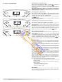
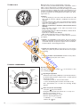
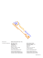
End User
Manual
SERIES
ACO 27
ACO 32
ACO 27
ACO 32
MFFI G.C.N:
MFFI G.C.N:
RFFI G.C.N:
RFFI G.C.N:
47-116-34
47-116-35
41-116-09
41-116-10
LEAVE THESE INSTRUCTIONS
WITH THE END USER
388www.heatingspares247.com
488
9HQ01274
BD8
Bradford,
Road
Hockney
Off
Estate
Ind.
Road
Thornton
3A,
Unit
Q
9H 8
8 38
D
B 88
d, 44
or 7
df 12
ra 0
B
d
oa
R
ey
kn
oc
H
ff
O
e
at
st
.E
nd m
I
d co
oa .
R 47
n s2
to re
rn pa
ho gs
n
,T i
A at
t3 he
ni .
U ww
w
Country of destination: GB/IE
Dear Customer,
TABLE OF CONTENTS
Thank you for choosing an ARISTON boiler.
We guarantee that your boiler is a reliable and
technically sound product.
This manual provides detailed instructions and
recommendations for correct use.
1.
2.
3.
4.
5.
6.
Remember to keep this manual along with the
Installation and Servicing Instruction manual
in a safe place for future reference i.e. by the
gas meter.
GENERAL INFORMATION
CONTROL PANEL
OPERATING INSTRUCTIONS
USEFUL INFORMATION
MECHANICAL TIME CLOCK
DIGITAL PROGRAMMER
page.
page.
page.
page.
page.
page.
3
4
6
9
10
10
IMPORTANT!
Your local MTS Servicing Centre is at your
complete disposal for all requirements.
Please read this manual carefully.
For additional information, please consult the “Installation and Servicing
Instructions.”
Keep this manual along with the Installation & Servicing Instructions
manual in a safe place for future reference.
Every attempt has been made to avoid errors of any kind in this manual,
the Management invites customers to inform of any inaccuracies which
they may find. This will help to improve our service.
GUARANTEE
2
388www.heatingspares247.com
488
9HQ01274
BD8
Bradford,
Road
Hockney
Off
Estate
Ind.
Road
Thornton
3A,
Repairs to the electric, water or gas circuits may
only be carried out by your local authorised
MTS Servicing Centre.
Unit
Q
9H 8
8 38
D
B 88
d, 44
or 7
df 12
ra 0
B
d
oa
R
ey
kn
oc
H
ff
O
e
at
st
.E
nd m
I
d co
oa .
R 47
n s2
to re
rn pa
ho gs
n
,T i
A at
t3 he
ni .
U ww
w
The guarantee on this appliance is valid for 60
months from the first day of installation by a
qualified CORGI registered engineer and
subject to an annual service carried out by a
qualified service engineer in line with MTS (GB)
LTD’s Servicing Schedule.
MTS (GB) Limited support the
initiative. In the Installation
and Servicing Instructions (Sections 11 and 12) you will find the
Commissioning Checklist and the Servicing Interval
Record, your installer must complete this, and show you how to
use it as it will give you important information about your boiler,
and heating system. Also when the boiler is serviced annually the
Service Interval Record must be completed. Please have the
Installation and Servicing Instructions to hand whenever you contact a service engineer or us.
1. GENERAL INFORMATION
All CORGI Registered Installers carry a CORGI ID card, and
have a registration number. Both should be recorded in your
boiler Log Book. You can check your installer is CORGI registered by calling CORGI direct on :- (01256) 372300.
The ACO MFFI range of boilers are combined appliances for the
production of Central Heating (C.H.) and Domestic Hot Water
(D.H.W.).
The ACO RFFI range of boilers are heating only boilers designed
for the production of Central Heating (C.H.) and Domestic Hot
Water (D.H.W.) in conjunction with an indirect storage cylinder.
By design, these appliances are for domestic use and must only
be used for this purpose.
The manufacturer declines all liability for damage caused by
improper or negligent use.
Q
9H 8
8 38
D
B 88
d, 44
or 7
df 12
ra 0
B
d
oa
R
ey
kn
oc
H
ff
O
e
at
st
.E
nd m
I
d co
oa .
R 47
n s2
to re
rn pa
ho gs
n
,T i
A at
t3 he
ni .
U ww
w
Do not allow children or inexperienced persons to use the appliance without supervision.
388www.heatingspares247.com
488
9HQ01274
BD8
Bradford,
Road
Hockney
Off
Estate
Ind.
Road
Thornton
3A,
Unit
If you smell gas in the room, do not turn on light switches, use
the telephone or any other object which might cause sparks.
Open doors and windows immediately to ventilate the room.
Shut the gas mains tap (on the gas meter) or the valve of the gas
cylinder and call your Gas Supplier immediately.
If you are going away for a long period of time, remember to shut
the mains gas tap or the gas cylinder valve. (This may not be necessary if the appliance is to be left operational for frost protection).
Before any intervention within the boiler it is first necessary
to isolate the electrical power supply by turning the external
switch to “OFF”.
3
27/32 MFFI
2. CONTROL PANEL
I
A
H
G
B
F
C
E
388www.heatingspares247.com
488
9HQ01274
BD8
Bradford,
Road
Hockney
Off
Estate
Ind.
Road
Thornton
3A,
Unit
Q
9H 8
8 38
D
B 88
d, 44
or 7
df 12
ra 0
B
d
oa
R
ey
kn
oc
H
ff
O
e
at
st
.E
nd m
I
d co
oa .
R 47
n s2
to re
rn pa
ho gs
n
,T i
A at
t3 he
ni .
U ww
w
D
Fig. 3.6
Button
Description
ON/OFF Button
“COMFORT” Function Button
Reset Button/
Flue Test**/ scroll through Functions Menu
Menu Button
Programming “+” key
Description
A
Green LED
(illuminated = burner on)
B
Time clock (Mechanical Version Shown)
C
Selector knob for Summer/Winter
Central Heating Temperature Adjustment Knob
D
Control Panel Cover
E
Domestic Hot Water Temperature Adjustment Knob
F
Heating System Pressure Gauge
G
“COMFORT” Function L.E.D
H
Red LED
(illuminated = boiler lockout)
I
Multi-function Display
Programming “-” key
** IMPORTANT!!
The Flue Test function will cause the boiler to run continuously on
maximum power. This function must only be activated by an authorised engineer.
4
27/32 RFFI SYSTEM
I
A
H
G
B
F
C
388www.heatingspares247.com
488
9HQ01274
BD8
Bradford,
Road
Hockney
Off
Estate
Ind.
Road
Thornton
3A,
Unit
Q
9H 8
8 38
D
B 88
d, 44
or 7
df 12
ra 0
B
d
oa
R
ey
kn
oc
H
ff
O
e
at
st
.E
nd m
I
d co
oa .
R 47
n s2
to re
rn pa
ho gs
n
,T i
A at
t3 he
ni .
U ww
w
FIG. 3.4
D
Button
Description
ON/OFF Button
NOT USED
Reset Button/
Flue Test**/ scroll through Functions Menu
Menu Button
Description
A
Green LED
(illuminated = burner on)
B
Time clock (Mechanical Shown - Optional)
C
Selector knob for Summer/Winter
Central Heating Temperature Adjustment Knob
D
Control Panel Cover
F
Heating System Pressure Gauge
G
NOT USED
H
Red LED
(illuminated = boiler lockout)
I
Multi-function Display
Programming “+” key
Programming “-” key
** IMPORTANT!!
The Flue Test function will cause the boiler to run continuously on
maximum power. This function must only be activated by an authorised engineer.
5
CAUTION!!
In the United Kingdom installation, start-up, adjustments
and maintenance must be performed by a CORGI registered
installer in accordance with the installation standards currently in effect, as well as with any and all local health and
safety standards i.e. CORGI.
3. OPERATING INSTRUCTIONS
O
In the Republic of Ireland the installation, and initial start-up
of the appliance must be carried out by a Competent Person
in accordance with the current edition of I.S.813 “ Domestic
Gas Installations”, and the current Building Regulations, reference should also be made to the current ETCI rules for
electrical installation.
Improper installation may cause damage or injury to individuals,
animals and personal property, for which the manufacturer will
not be held liable.
To ensure efficient and safe operation and to maintain the 5 year
guarantee, the appliance MUST be serviced annually by a competent person and the MTS Servicing schedule completed and
returned to MTS GB Limited.
If it is known or suspected that a fault exists on the appliance, it
must not be used until the fault has been corrected by a competent person.
MFFI
Helpful Suggestions
To get the most out of your boiler, we have provided you with some useful advice on proper use and maintenance:
388www.heatingspares247.com
488
9HQ01274
BD8
Bradford,
Road
Hockney
Off
Estate
Ind.
Road
Thornton
3A,
Unit
F
Q
9H 8
8 38
D
B 88
d, 44
or 7
df 12
ra 0
B
d
oa
R
ey
kn
oc
H
ff
O
e
at
st
.E
nd m
I
d co
oa .
R 47
n s2
to re
rn pa
ho gs
n
,T i
A at
t3 he
ni .
U ww
w
RFFI SYSTEM
Filling Instructions
- Periodically check the system pressure using the pressure gauge “F”
and make sure that the pressure is between 1.0 and 1.5 bar when the
system is off and cool. If the pressure is below the minimum recommended value, the pressure must be brought into the acceptable
range. To refill the system, it will be necessary to connect the flexible
hose “P” to the cold water inlet and central heating flow connections
(two black quarter turn handles underneath the boiler), then, open the
two black quarter turn handles, water will now be heard passing into
the appliance and the black needle on the pressure gauge will start
to rise. Once the pressure gauge “F” reads 1.5 bar close the valves
again and disconnect the flexible hose.
If the pressure level drops on a frequent basis, it is likely that there is
a water leak in the system. If this is the case, your installer must
inspect the system.
NOTE: ON RFFI MODELS, THE INSTALLER MAY HAVE FITTED A REMOTE FILLING
LOOP THAT MAY NOT RESEMBLE THAT SHOWN IN DIAGRAM P.
VALVES WITH 1/4
TURN HANDLES
FILLING LOOP
6
P
- The outer panels of the boiler's case must only be cleaned with a
damp cloth, do not use abrasive cleaners. The control panel can be
wiped with either a damp or dry cloth. Spray polishes must not be
used on the control panel surface or knobs. Care must be taken in
preventing any liquid entering the appliance.
- If the water is exceptionally hard, install a water softener so that the
efficiency of the boiler remains the same over time, as this will consume less gas.
- To improve comfort levels and take full advantage of the heat produced by the boiler, it is necessary that a room thermostat and an outdoor sensor be installed.
- When the boiler is not in use for prolonged periods shut it down by
pushing the
button to the off position and close the gas and
water isolation valves.
(Important!) This will disable the anti-frost device (see page 9) - if the
period of disuse is very cold it will also be necessary to drain the heating system of water.
If you wish to leave the anti-frost device active, it is necessary to leave
the boiler on: this will not safeguard from possible interventions which
may impair this function.
- It is good practice to clean and service the appliance and Central
Heating System every year.
Call a CORGI registered gas installer.
Adjusting the heating
It is possible to set the temperature of the Central Heating system
by adjusting the knob “C”. By positioning the indicator somewhere between 1 and 6, a temperature may be obtained which
varies from approximately 38˚C to about 82˚C.
The water temperature in the primary circuit is shown on the display.
M
Start-up Procedure
Before starting the boiler, check the following:
- The water pressure on the pressure gauge “F” is between 1 and
1.5 bar;
- That the external gas cock “M” and “N” and the inlet for domestic
water are open.
These models are equipped with electronic ignition (there is no pilot
light).
To switch the boiler on, push the
button. Turn the knob “C” to
the summer “
” or winter position; a centralised electronic control
unit will automatically light the main burner when needed without any
intervention from the outside (green LED “A” will illuminate when the
burner is on).
If the burner does not light within the pre-set safety time limit, the display will show an error code and the red LED “H” will illuminate.
To reset the ignition system, the reset button
must be pressed.
Should the system fail to light a second time, check to make sure that
the gas cock is open. If the problem persists, contact the Customer
Service Helpline.
N
A
H
summer
Winter and Summer Operating Modes
In the “Winter” operating mode, the boiler will produce both
Central Heating and Domestic Hot Water. In the “Summer” operating mode, the boiler will produce only Domestic Hot Water.
Using the knob on the control panel, the user can select “winter”
”
or “summer” operating mode. Keeping the knob “C” at the “
position selects the “summer” operating mode. “Winter” operating
mode may be selected by positioning the knob “C” between the
min. and max. settings.
388www.heatingspares247.com
488
9HQ01274
BD8
Bradford,
Road
Hockney
Off
Estate
Ind.
Road
Thornton
C
3A,
C
Unit
Q
9H 8
8 38
D
B 88
d, 44
or 7
df 12
ra 0
B
d
oa
R
ey
kn
oc
H
ff
O
e
at
st
.E
nd m
I
d co
oa .
R 47
n s2
to re
rn pa
ho gs
n
,T i
A at
t3 he
ni .
U ww
w
winter
Note: The “Summer” mode is only available for MFFI models.
External (room) thermostat control
If an external (room) thermostat is installed, it is recommended
that the temperature of the Central Heating system be set by
means of the knob “C”, leaving it at max in order to obtain the
best performance from the boiler and to allow the regulation of the
room temperature to function efficiently.
C
C
Setting the hot water for domestic use (MFFI only)
Both in the winter and summer mode, the temperature of the
Domestic Hot Water may be adjusted by using knob “E”. A delivery temperature for the water may be chosen in a range from 36˚C
to about 56˚C, depending on the flow rate of the water and the
position of the knob between the min. and max. settings.
To increase water temperature, turn knob “E” to max. and reduce
the water flow rate at the tap.
The water temperature in the primary circuit is shown on the
display.
E
Comfort Function (MFFI only)
The supply of water for domestic use can become more convenient by means of the “COMFORT” function, which maintains the
secondary exchanger at a preset temperature when the boiler is
not running; thereby allowing a quicker delivery of domestic water
when required. This function is activated by pressing
the
button on the control panel. When the function is on, a
yellow L.E.D. “G” on the control panel will illuminate.
7
Note: If the “COMFORT” function is on during the pump overrun
period, it will be temporarily deactivated. The yellow L.E.D. “G”
will remain on to indicate that the boiler will resume the “COMFORT” mode once the pump overrun period is complete.
Periodic operation of the appliance will occur regardless of
demand on the boiler. This function is normal operation.
The COMFORT mode will automatically de-activate in low water
usage periods i.e. overnight. Turning on a tap will re-activate the
function.
G
Turning Off the Heating
Installation without a room thermostat:
To turn off the heating, turn the selector knob “C” to “
boiler will still provide domestic hot water.
”. The
Installation with a room thermostat:
To turn off the heating, turn the selector knob “C” to “
”. The
boiler will still provide hot water for domestic use. With a room
thermostat, turn the dial of the thermostat down to the lowest setting.
C
Turning off the boiler
To turn the boiler off, push the button
off.
; the display will go
388www.heatingspares247.com
488
9HQ01274
BD8
Bradford,
Road
Hockney
Off
Estate
Ind.
Road
Thornton
3A,
Unit
Q
9H 8
8 38
D
B 88
d, 44
or 7
df 12
ra 0
B
d
oa
R
ey
kn
oc
H
ff
O
e
at
st
.E
nd m
I
d co
oa .
R 47
n s2
to re
rn pa
ho gs
n
,T i
A at
t3 he
ni .
U ww
w
Display: Viewing Normal Functions
When the system is operating, i.e. while the boiler is fulfiling its normal
functions, the left-hand display will show a letter indicating the following functions:
LEFT
RIGHT
0
C
c
d
h
No Request for Heat (Stand By)
Central Heating
Pump Overrun for Heating
Domestic Hot Water
Pump Overrun for Domestic Hot Water
The right-hand display (two-digit) shows:
- in heating mode: temperature of heating system flow;
- in domestic hot water mode: temperature of the DHW leaving
the boiler (MFFI only)
Boiler Shutdown
The boiler is equipped with safety devices which intervene in
certain situations to shutdown the boiler. Some of these situations are signalled by the boiler and can be corrected by the
user.
8
Shutdown Due to Ignition Failure
This anomaly is indicated by “A01” on the display. To reset the
boiler, press and then release the reset button
.
At this point, the electronic ignition system will attempt to light the
burner again.
Should the boiler fail to ignite a second time, check that the
external gas cock is open. If the problem persists, contact an
Authorised Service Centre.
4. USEFUL INFORMATION
Shutdown Due to Overheating
This anomaly is indicated by “A 03” on the display. The boiler has
shutdown because the safety thermostat detected that the boiler
temperature has exceeded the maximum limit.
To reset this state, wait until the boiler has cooled and press
the
button.
If the safety thermostat operates on a frequent basis, contact an
Authorised Service Centre.
Shutdown Due to Insufficient Water Circulation
This anomaly is indicated by “A 02” on the display.
One of the possible causes of this shutdown situation could be the
lack of water in the boiler or water circulation failure in the primary
heating circuit.
Check the system pressure on the pressure gauge “F” and, if it is
less than 0.5 bar, try bringing the system pressure up to a mean
value of 1.0 bar by opening the water inlet valve (see page 6 for
further instructions). Then reset by pressing the
button.
388www.heatingspares247.com
488
9HQ01274
BD8
Bradford,
Road
Hockney
Off
Estate
Ind.
Road
Thornton
3A,
Unit
Q
9H 8
8 38
D
B 88
d, 44
or 7
df 12
ra 0
B
d
oa
R
ey
kn
oc
H
ff
O
e
at
st
.E
nd m
I
d co
oa .
R 47
n s2
to re
rn pa
ho gs
n
,T i
A at
t3 he
ni .
U ww
w
Other Shutdown Situations
Should a shutdown situation indicated on the left display by the
letter E (E 04, E 05, E06, .....etc.) occur, contact an Authorised
Service Centre.
If instead the display shows one of the shutdown situations indicated by the following letters and figures, A 07, A 33, A 97, A 98,
A 99, try resetting the boiler by pressing the reset button
. If
the boiler shuts off again, contact an Authorised Service Centre.
Anti-frost device
The anti-frost function acts on the central heating flow temperature probe, independently from other regulations, when the electrical supply is turned on.
If the primary circuit temperature falls below 8°C the pump will run
for 2 minutes.
After the two minutes of circulation (fixed) the boiler will check the
following:
a) if the central heating flow temperature is > 8°C, the pump stops;
b) if the central heating flow temperature is between 3 and 8°C,
the pump will run for another two minutes;
c) if the central heating flow temperature is < 3°C, the burner will
fire (heating position) at minimum power until the temperature
reaches 33°C, the burner will go out and the pump will continue to
run for two minutes.
If the flow temperature remains between 3-8°C the pump will continue to run for two minutes for a maximum of 10 times unless a
temperature above 8°C is detected in the central heating flow,
after this the the burner will fire.
If lockout is caused by overheat the burner is kept OFF.
NOTE: In all cases, the circulation takes place in the central
heating system.
The anti-frost device activates only when (with the boiler operating correctly):
- the system pressure is correct;
- the boiler is electrically powered;
- there is a supply of gas.
IMPORTANT!
DUE TO THE HIGH EFFICIENCY NATURE OF THE APPLIANCE, THE FLUE WILL
PRODUCE PLUMES OF CONDENSED WATER VAPOUR, THIS IS NORMAL OPERATION FOR A CONDENSING BOILER.
9
5. TIME CLOCK
NOTE: the time clock is for central heating control only.
The time clock is provided with 96 switches, called riders, each of
which covers a time interval of 15 minutes (four per hour).
When a rider is switched from the inside (off setting) to the outside
of the clock border (on setting), the circuit is closed (switch on) for
a period of 15 minutes and then the boiler starts if the room thermostat (if installed) or the heating thermostat require heat (heating function on).
EXAMPLE
To set the heating of your home in the time interval from 7.00
am to 8.00 am and from 7.00 pm to 10.00 pm every day (see
diagram):
- rotate the outer ring of the clock in a clockwise direction until the
correct time of day (24h) lines up with the arrow on the clock (at
approx. 2 o’clock position);
- under no circumstances should the minute hand be moved
manually;
- make sure all the switches, i.e. the riders, are placed on the
inside of the clock border;
- pull outward the riders for 7.00 am and 8.00 am, and then all riders between these two;
- repeat this for 7.00 pm and 10.00 pm.
Other heating intervals may be set in the same way.
The clock is provided with a selector switch with three positions
(see figure):
Q
9H 8
8 38
D
B 88
d, 44
or 7
df 12
ra 0
B
d
oa
R
ey
kn
oc
H
ff
O
e
at
st
.E
nd m
I
d co
oa .
R 47
n s2
to re
rn pa
ho gs
n
,T i
A at
t3 he
ni .
U ww
w
1. Position “I” CONSTANT: in this position, the clock circuit is
always closed (switch on), therefore the boiler will constantly be
on and will only shut off upon the request of the room thermostat (if installed) or the heating thermostat;
388www.heatingspares247.com
488
9HQ01274
BD8
Bradford,
Road
Hockney
Off
Estate
Ind.
Road
Thornton
3A,
Unit
2. Position “O” HEATING OFF: in this position, the clock circuit is
always open (switch off) and the boiler will therefore never ignite
for heating;
3. “Central” Position PROGRAMMING ACTIVE: in this position,
the programming set by the user is active.
6. DIGITAL PROGRAMMER
Operating the time switch
The steps marked with the symbol “
out a switching program.
Manual switch
Summer and
winter time
setting
Reset
Enter
the hours
Prog
.
Enter
switching
times
Weekdays
flash
Imput
time
Enter
minutes
” are necessary to carry
Preparing for Operation
Activate the “Res” switch (=RESET) to reset the time switch to
its default setting (activate using a pencil or similar pointed
instrument). Do this:
- every time you wish to “reset” the time switch
- to erase all switching times and the current time of day.
After approximately two seconds the following display
appears:
Day
Status
Enter
weekday/s
10
Enter current time and weekday
- Keep the “ ” key pressed down
During the summer time period press the +/- 1h key once.
Enter the hour using the “h” key
Enter the minutes using the “m” key
Enter the day using the “Day” key
1 = “Monday”..............7 = Sunday
- Release the “ ” key.
Changing the programmed switching times
Press the “Prog” key repeatedly until the switching time you want
to change is displayed. You can now enter the new data. See point
“Entering the switching times”.
Notes on storing switching times:
If you end your entry of the switching times by pressing the “Prog”
key, then the switching time you have entered will be stored and
the next memory location displayed.
AM / PM time display
If you press the “+/-1h” and “h” keys at the same time, the time display switches into the AM/PM mode.
388www.heatingspares247.com
488
9HQ01274
BD8
Bradford,
Road
Hockney
Off
Estate
Ind.
Road
Thornton
3A,
Unit
Q
9H 8
8 38
D
B 88
d, 44
or 7
df 12
ra 0
B
d
oa
R
ey
kn
oc
H
ff
O
e
at
st
.E
nd m
I
d co
oa .
R 47
n s2
to re
rn pa
ho gs
n
,T i
A at
t3 he
ni .
U ww
w
Entering the switching times
You have 20 memory Iocations available. Each switching time
takes up one memory location.
Keep pressing the “Prog” key until a free memory location is
shown in the display “– –:– –”.
Programme ON or OFF with the “
” key:
“ ”= OFF; “ ”= ON
Enter the hour using “h”
Enter the minutes using “m”
If a switching command is to be carried out every day (1 2 3
4 5 6 7) then store using the “ ” key, otherwise select the
day(s) it is carried out by using the “Day” key.
When the day seIection is left bIank, the programmed switching instruction operates at the same time every day
1 2 3 4 5 6 = Monday – Saturday
12345
= Monday – Friday
67
=Saturday – Sunday
In addition, a complete switching command is stored automatically after around 90 seconds provided no other key is pressed.
The time switch then enters the automatic operating mode and
displays the current time again.
Deleting individual switching times
Press the “Prog” key repeatedly until the switching time you wish
to delete is shown in the display. Then set to “– –” using the “h” or
“m” key and keep the “ ” key pressed down for around 3 seconds. The switching time is now erased and the current time is displayed.
Selection of single days: 1 = Mon. .............. 2 =Tues.
Save the switching time with the “ ” key.
The time switch enters the automatic operating mode and displays the current time of day.
Begin any further entry of a switching time with the “Prog”
switch. If your entry is incomplete, the segments not yet
selected will blink in the display. After programming is completed, and you return the time clock to the current time display with the “ ” key, the time clock will not activate any
switching instruction required for the current time. You may
need to manually select the desired switching state with the
“
” key. Thereafter, as the unit encounters further switching instructions in the memory in real time, it will correctly activate all subsequent switching instructions.
Manual Override Switch “
”
With the “
” you can change the current setting at any time. The
switching program already entered is not altered.
Reading the programmed switching times
Pressing the “Prog” key displays the programmed switching times until
the first free memory location appears in the display “– – : – –”.
If you now press the “Prog” key once again, the number of free
memory Iocations will be displayed, e.g. “18”. If all memory locations are occupied, the display “00” appears.
11
388www.heatingspares247.com
488
9HQ01274
BD8
Bradford,
Road
Hockney
Off
Estate
Ind.
Road
Thornton
3A,
Unit
Q
9H 8
8 38
D
B 88
d, 44
or 7
df 12
ra 0
B
d
oa
R
ey
kn
oc
H
ff
O
e
at
st
.E
nd m
I
d co
oa .
R 47
n s2
to re
rn pa
ho gs
n
,T i
A at
t3 he
ni .
U ww
w
Manufacturer:
Merloni TermoSanitari SpA - Italy
Commercial subsidiaries:
MTS (GB) Limited
MTS Building
Hughenden Avenue
High Wycombe
Bucks HP13 5FT
MTS Heating Limited
Damastown Industrial Park
Damastown Avenue
Mulhuddart
Dublin 15
Telephone: (01494) 755600
Telephone: (01) 810 3723
Fax: (01494) 459775
Fax: (01) 810 3727
Internet: www.mtsgroup.com/uk
Internet: www.mtsgroup.com/ie
E-mail: [email protected]
E-mail: [email protected]
Technical Advice: 0870 241 8180
Technical Advice: (01) 437 0121
Customer Service: 0870 600 9888
Customer Service: (01) 437 0121
099841833112