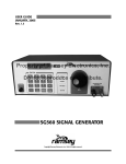
1
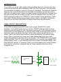
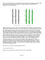
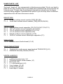
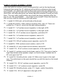
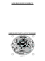
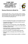
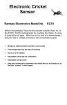
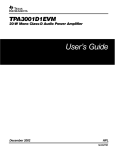
Universal Audio Amplifier Ramsey Electronics Model No. UAM2 Need more audio “punch” for a project? Build your own powered speaker or juice up that audio kit with this high quality audio amp. Maximum 20 Watt screaming output for any application; lower gain settings with the change of a jumper. • Whopping 20W output at 18V. • Runs on 8V to 18V DC. • SNR: 102dB at 15W into 8Ω, 18V 95dB at 10W into 4Ω, 12V • THD + N: 1% at 15W into 8Ω, 18V .2% at 10W into 4Ω, 12V • Square board for screw mounting, or circular “break out” board for attaching directly to speaker magnet. • Line level input • Adjustable gain: 12dB, 18dB, 23.6dB, 32dB • Remote shutdown input UAM2• 1 PARTIAL LIST OF AVAILABLE KITS: RAMSEY TRANSMITTER KITS • FM10A, FM25B FM Stereo Transmitters • AM1, AM25 Transmitter RAMSEY RECEIVER KITS • FR1 FM Broadcast Receiver • AR1 Aircraft Band Receiver • SR2 Shortwave Receiver • AA7 Active Antenna • SC1 Shortwave Converter RAMSEY HOBBY KITS • SG7 Personal Speed Radar • SS70A Speech Scrambler/ Descrambler • TT1 Telephone Recorder • SP1 Speakerphone • MD3 Microwave Motion Detector • PH14 Peak hold Meter • LC1 Inductance-Capacitance Meter RAMSEY AMATEUR RADIO KITS • HR Series HF All Mode Receivers • DDF1 Doppler Direction Finder Kit • QRP Series HF CW Transmitters • CW7 CW Keyer • QRP Power Amplifiers RAMSEY MINI-KITS Many other kits are available for hobby, school, scouts and just plain FUN. New kits are always under development. Write or call for our free Ramsey catalog. UAM2 Universal Audio Amp Ramsey Electronics publication No. UAM2 Rev. 1.1 October 2003 COPYRIGHT ©2003 by Ramsey Electronics, Inc. 590 Fishers Station Drive, Victor, New York 14564. All rights reserved. No portion of this publication may be copied or duplicated without the written permission of Ramsey Electronics, Inc. Printed in the United States of America. UAM2• 2 Ramsey Publication No. UAM2 Manual Price Only $5.00 KIT ASSEMBLY AND INSTRUCTION MANUAL FOR Universal Audio Amplifier TABLE OF CONTENTS Introduction to the UAM2 .................................. 4 UAM2 Circuit Description .................................. 4 “Learn-As-You-Build” Kit Assembly ................... 6 Parts List ........................................................... 8 Assembly Steps ................................................. 9 Setup and Testing ........................................... 11 Troubleshooting Guide ..................................... 11 UAM2 Parts Layout Diagram ........................... 13 UAM2 Schematic ............................................. 13 Ramsey Kit Warranty ....................................... 15 RAMSEY ELECTRONICS, INC. 590 Fishers Station Drive Victor, New York 14564 Phone (585) 924-4560 Fax (585) 924-4555 www.ramseykits.com UAM2• 3 INTRODUCTION The UAM2 is a small, high quality audio amplifier that you can plug any line level source into and get a whopping 20W out! So if you want, you can plug your portable cd player in and run your big ol’ speaker! The board is made so that you can mount it directly onto the back of a speaker or just use it as is with the mounting holes. It puts out great quality sound with lots of power and the active parts are all surface mount! You’ll be amazed when you fire it up, 20W is going through a tiny TSSOP IC, and it doesn’t even get warm. There are 4 gain settings giving you a rough volume adjust, and also a shutdown input so you can turn the UAM2 off without disconnecting the power. UAM2 CIRCUIT DESCRIPTION The UAM2 is built around the Texas Instruments TPA3001D1 audio amplifier. It is a 20W audio amp in a 24 pin TSSOP package that we have soldered onto the board for you. We know that many of our customers have super skills, but we soldered it on for the sake of the ones that might have a hard time with a small part like that. All the other parts are left for you to solder, and if you have some surface mount experience it should be really easy. If this is your first kit, it may be a little challenging, but if you work slowly and carefully it should come out all right. The TPA3001D1 is a class D audio amplifier. The “D” is the magic behind how a tiny chip can handle 20W without going “poof”. If you already know how a class D amplifier works, you may skip this section. If, however, this is your first exposure to class D amps as it was for me when I designed this kit, keep reading and allow me to enlighten you. outp audio input comparator and switch outn filter differential output reference signal output to speaker UAM2• 4 First, your audio input is compared to a high frequency reference signal. This generates two squarewave outputs. These outputs change phase in response to the audio input. audio input > 0 audio input = 0 volts When the audio input is 0 volts, the two outputs are nearly in phase and the differential voltage is almost zero most of the time, just little spikes. But, when the audio input is greater than zero volts, the two outputs are out of phase and the differential voltage becomes greater, that is, its duty cycle increases. The voltage is high a greater percentage of the time. This differential voltage is filtered to produce a sine wave that is sent to the speaker. The magic of all this is that the circuitry needed to carry out these operations can be digital because all the waveforms are squarewaves; the voltage is either high or low, on or off. until they go through the filter. This means that the circuitry need only have switches to turn the voltage on and off. Switches don’t consume power so a tiny chip can be used without getting hot. This is in contrast to other types of amplifiers that have resistive elements in them which burn up lots of power. They have to have big fat transistors in them that can handle lots of heat. For more info on class D amps check out the TPA3001D1 data sheet at: http://focus.ti.com/lit/ds/symlink/tpa3001d1.pdf Or a Georgia Tech site: http://users.ece.gatech.edu/~mleach/ece4435/f01/ClassD2.pdf UAM2• 5 RAMSEY Learn-As-You-Build KIT ASSEMBLY There aren’t that many solder connections on the UAM2 printed circuit board, but you should still practice good soldering techniques. • • • • • Use a 25-watt soldering pencil with a clean, sharp tip. Use only rosin-core solder intended for electronics use. Use bright lighting; a magnifying lamp or bench-style magnifier may be helpful. Do your work in stages, taking breaks to check your work. Carefully brush away wire cuttings so they don't lodge between solder connections. We have a two-fold "strategy" for the order of the following kit assembly steps. First, we install parts in physical relationship to each other, so there's minimal chance of inserting wires into wrong holes. Second, whenever possible, we install in an order that fits our "Learn-As-You Build" Kit building philosophy. This entails describing the circuit that you are building instead of just blindly installing components. We hope that this will not only make assembly of our kits easier, but help you to understand the circuit you’re constructing. For each part, our word "Install" always means these steps: 1. Pick the correct part value to start with. 2. Insert it into the correct PC board location. 3. Orient it correctly, follow the PC board drawing and the written directions for all parts - especially when there's a right way and a wrong way to solder it in. (Diode bands, electrolytic capacitor polarity, transistor shapes, dotted or notched ends of IC's, and so forth.) 4. Solder all connections unless directed otherwise. Use enough heat and solder flow for clean, shiny, completed connections. SURFACE MOUNT COMPONENT SOLDERING INSTRUCTIONS: You’ll notice that the circuit board contains only a few holes for component leads to pass through. This is because the SMT components will be affixed to the “solder” side of the PC board, the side that contains the PC traces. Be aware that the component view for assembly is looking at the solder side of the PC board. Patience is the key when installing surface mount components. Typically, the first step (after identifying the component) is to “tin” one of the PC traces that will connect to the part. Once this is accomplished, the part can UAM2• 6 be installed by holding it with tweezers in contact with the “tinned” trace and re-heating the solder (see the associated diagrams). Another commonly used technique is to glue the surface mount components to the printed circuit board before soldering. The procedure is to take a small amount of glue (usually with a pin or toothpick) and “dab” the circuit board in the place where the component will be affixed. Be careful not to apply too much glue as when the part is placed it may “squash” the glue underneath the soldering tabs of the component. Carefully place the part into position, and when the glue dries, solder the connection. UAM2• 7 UAM2 PARTS LIST Sort and “check off” the components in the boxes provided. We do our best to pack all our kits correctly but it is possible that a mistake has occurred and we missed a part. Please note that physical descriptions of parts are for those currently being shipped. Sometimes the parts in your kit may have a different appearance but still have the same values. RESISTORS 2 51 ohm surface mount resistor [510] (R1,R5) 4 120K ohm surface mount resistor [124] (R2,R3,R4,R6) CAPACITORS 7 1 uF surface mount capacitor (C2,C3,C5,C6,C7,C9,C11) 2 .001 uF surface mount capacitor (C14,C15) 2 .22 uF surface mount capacitor (C12,C13) 1 .47 uF surface mount capacitor (C8) 1 220 pF surface mount capacitor (C10) 1 1500 uF surface mount electrolytic capacitor (C1) INDUCTORS 2 surface mount ferrite bead (L1,L2) SEMICONDUCTORS 1 2 TPA3001D1 audio power amp [marked TPA3001D1] (U1) 20BQ030 Schottky diodes (D3,D4) MISCELLANEOUS 1 1 1 1 2 2 1 red/black twisted wire, 2 ft 3 terminal green screw header (J7) RCA jack (J3) 2.1 mm power jack (J4) 2 pin header (J1,J2) screw posts (J5,J6) foam tape, 4 inches UAM2• 8 UAM2 PC BOARD ASSEMBLY STEPS Let’s start with the surface mount components first, and do the big through hole parts last, except for J3, which we will install as a reference part to get our bearings. You want to be careful about how much heat you apply to the teeny parts. Just get the tabs and circuit board pads hot enough to get the solder to flow. We have also given you extra caps and resistors in case you torch them. The one really tough surface mount part has been installed at the factory for you. Be very thankful. . . it’s a bear to do yourself!! Orient the board so that you can read the writing and let’s get going. 1. Install J3, RCA jack, at the left side of the board. 2. Install R2 and R3, 120K resistors [marked 124], near J3. These are pullups for J1 and J2, which are the gain setting jumpers. 3. Install C7, 1 uF surface mount capacitor, to the right of R2. 4. Install C5, 1 uF surface mount capacitor, to the right of R3. 5. Install C8, .47 uF surface mount capacitor, just below R7. 6. Install C9, 1 uF surface mount capacitor, above C5. 7. Install C6, 1 uF surface mount capacitor, next to C9. 8. Install C10, 220 pF surface mount capacitor, next to C6. 9. Install R4, 120K surface mount resistor, next to C10. 10. Install R5, 51 ohm surface mount resistor, above R4. 11. Install C12, .22 uF surface mount capacitor, to the right of R5. 12. Install L2, surface mount ferrite bead, next to C12. This acts a trap for high frequencies at the speaker output, so the kit doesn’t radiate lots of RF and upset the FCC. 13. Install D4, Schottky diode, under L2. Make sure it goes in the right way. The white band on the part should line up with the band on the board drawing. 14. Install C14, .001 uF surface mount capacitor, next to D4. 15. Install C11, 1 uF surface mount capacitor, under D4. 16. Install D3, Schottky diode, under C11. Again, watch the polarity. 17. Install C15, .001 uF capacitor to the right of D3. UAM2• 9 18. Install L1, surface mount ferrite bead, under D3. 19. Install C2, 1 uF surface mount capacitor, under L1. 20. Install C13, .22 uF surface mount capacitor, to the left of C2. 21. Install R1, 51 ohm surface mount resistor, to the left of C13. 22. Install C3, 1 uF surface mount capacitor, to the left of R1. 23. Install R6, 120K ohm surface mount resistor, down and to the left of C3. 24. Install C1, that big ol’ beast electrolytic surface mount capacitor. Yeah, you know the one I’m talking about, that big shiny one. BE REALLY SURE IT GOES IN THE RIGHT WAY. During initial testing for this kit, someone soldered it in backwards, and well, there was an incident. The black band indicates the negative lead. It’s pretty easy to solder in. The leads are bigger so it will take a little more solder than the teeny parts. Okay, enough with these weenie parts. Let’s solder in the through holes. 25. Install J6 and J5, the big silver screw post things on the right side of the board. Don’t be afraid to use enough solder to hold them in well. 26. Install J7, the green three terminal block thingy at the bottom of the board. 27. Install J4, the power jack, lower left of the board. Be sure to use enough solder. 28. Install J1 and J2, the two pin headers at the upper right left of the board. 29. Install, wait, uh, I guess that’s it! Now it’s testing time. UAM2• 10 SETUP AND TESTING Well, setup and testing for this kit is really easy. Just plug in a line level or even headphone level audio source into J3. Use J1 and J2 to set the gain. Use the chart below: J2 J1 Gain(dB) ON ON 12 ON OFF 18 OFF ON 23.6 OFF OFF 32 ‘ON’ means the jumper block is on the pins, and ‘OFF’ means it isn’t. Start out at minimum gain to test. Plug your 8-12V power source in, connect a speaker to J5 and J6, and feel the awesome power of your UAM2!!!!!! If everything works ok, crank the gain up to max by pulling out both jumper blocks. Hear that sound! OOOO! Feel that chip not get hot! AHHH!!! Unless it doesn’t work, then…. The long black and red twisted pair wire is for you to connect your speaker to the UAM2. The green screw terminal block is there in case you wish to connect your power source there instead of at the power jack, J4. The pins are labeled “VCC” and “GND” for your positive and negative supply. The third terminal on the block is labeled SD. This stands for “shutdown” and this pin can be connected to ground to turn the unit off instead of pulling the power plug. You can connect a switch to ground at that point to have an ON/OFF for the UAM2. UAM2• 11 SETUP AND TESTING Well, setup and testing for this kit is really easy. Just plug in a line level or even headphone level audio source into J3. Use J1 and J2 to set the gain. Use the chart below: ‘ON’ means the jumper block is on the pins, and ‘OFF’ means it isn’t. Start out at minimum gain to test. Plug your 8-12V power source in, connect a speaker to J5 and J6, and feel the awesome power of your UAM2!!!!!! If everything works ok, crank the gain up to max by pulling out both jumper blocks. Hear that sound! OOOO! Feel that chip not get hot! AHHH!!! Unless it doesn’t work, then…. TROUBLESHOOTING GUIDE Well, this being a surface mount kit and all, if something doesn’t work it’s probably because one of the teeny parts didn’t get soldered in or got shorted. Check all your connections with a magnifier if you have one, and make sure they all look good. Of course check the polarity on the electrolytic cap and the diodes. There’s not much else that could be messed up with this kit. The IC is pretty tough. It has output short-to-ground, short-to-supply, short-together, and thermal overload protection. If you short it, or somehow overheat it, disconnect and reconnect power to clear the short. UAM2• 12 UAM2 MAIN BOARD SCHEMATIC UAM2 BOARD PARTS LAYOUT DIAGRAM UAM2• 13 CONCLUSION We sincerely hope that you will enjoy the use of this Ramsey product. As always, we have tried to compose our manual in the easiest, most “user friendly” format that is possible. As our customers, we value your opinions, comments, and additions that you would like to see in future publications. Please submit comments or ideas to: Ramsey Electronics Inc. Attn. Hobby Kit Department 590 Fishers Station Drive Victor, NY 14564 or email us at: [email protected] And once again, thanks from the folks at Ramsey! UAM2• 14 The Ramsey Kit Warranty Please read carefully BEFORE calling or writing in about your kit. Most problems can be solved without contacting the factory. Notice that this is not a "fine print" warranty. We want you to understand your rights and ours too! All Ramsey kits will work if assembled properly. The very fact that your kit includes this new manual is your assurance that a team of knowledgeable people have field-tested several "copies" of this kit straight from the Ramsey Inventory. If you need help, please read through your manual carefully, all information required to properly build and test your kit is contained within the pages! However, customer satisfaction is our goal, so in the event that you do have a problem, take note of the following. 1. DEFECTIVE PARTS: It's always easy to blame a part for a problem in your kit, Before you conclude that a part may be bad, thoroughly check your work. Today's semiconductors and passive components have reached incredibly high reliability levels, and its sad to say that our human construction skills have not! But on rare occasions a sour component can slip through. All our kit parts carry the Ramsey Electronics Warranty that they are free from defects for a full ninety (90) days from the date of purchase. Defective parts will be replaced promptly at our expense. If you suspect any part to be defective, please mail it to our factory for testing and replacement. Please send only the defective part (s), not the entire kit. The part(s) MUST be returned to us in suitable condition for testing. Please be aware that testing can usually determine if the part was truly defective or damaged by assembly or usage. Don't be afraid of telling us that you 'blew-it', we're all human and in most cases, replacement parts are very reasonably priced. 2. MISSING PARTS: Before assuming a part value is incorrect, check the parts listing carefully to see if it is a critical value such as a specific coil or IC, or whether a RANGE of values is suitable (such as "100 to 500 uF"). Often times, common sense will solve a mysterious missing part problem. If you're missing five 10K ohm resistors and received five extra 1K resistors, you can pretty much be assured that the '1K ohm' resistors are actually the 'missing' 10 K parts ("Hum-m-m, I guess the 'red' band really does look orange!") Ramsey Electronics project kits are packed with pride in the USA. If you believe we packed an incorrect part or omitted a part clearly indicated in your assembly manual as supplied with the basic kit by Ramsey, please write or call us with information on the part you need and proof of kit purchase. 3. FACTORY REPAIR OF ASSEMBLED KITS: To qualify for Ramsey Electronics factory repair, kits MUST: 1. NOT be assembled with acid core solder or flux. 2. NOT be modified in any manner. 3. BE returned in fully-assembled form, not partially assembled. 4. BE accompanied by the proper repair fee. No repair will be undertaken until we have received the MINIMUM repair fee (1/2 hour labor) of $25.00, or authorization to charge it to your credit card account. 5. INCLUDE a description of the problem and legible return address. DO NOT send a separate letter; include all correspondence with the unit. Please do not include your own hardware such as nonRamsey cabinets, knobs, cables, external battery packs and the like. Ramsey Electronics, Inc., reserves the right to refuse repair on ANY item in which we find excessive problems or damage due to construction methods. To assist customers in such situations, Ramsey Electronics, Inc., reserves the right to solve their needs on a case-by-case basis. The repair is $50.00 per hour, regardless of the cost of the kit. Please understand that our technicians are not volunteers and that set-up, testing, diagnosis, repair and repacking and paperwork can take nearly an hour of paid employee time on even a simple kit. Of course, if we find that a part was defective in manufacture, there will be no charge to repair your kit (But please realize that our technicians know the difference between a defective part and parts burned out or damaged through improper use or assembly). 4. REFUNDS: You are given ten (10) days to examine our products. If you are not satisfied, you may return your unassembled kit with all the parts and instructions and proof of purchase to the factory for a full refund. The return package should be packed securely. Insurance is recommended. Please do not cause needless delays, read all information carefully. UAM2• 15 TABLE OF CONTENTS Introduction to the UAM2 .................................. 4 UAM2 Circuit Description .................................. 4 Parts List ........................................................... 8 Assembly Steps ................................................. 9 Troubleshooting Guide..................................... 11 UAM2 Parts Layout Diagram ........................... 13 UAM2 Schematic ............................................. 13 Ramsey Kit Warranty ....................................... 15 REQUIRED TOOLS • Soldering Iron (WLC100) • Thin Rosin Core Solder (RTS12) • Needle Nose Pliers (MPP4 or RTS05) • Small Diagonal Cutters (RTS04) ADDITIONAL SUGGESTED ITEMS Helping Hands Holder for PC Board/Parts (HH3) • Technician’s Tool Kit (TK405) • Desoldering Braid (RTS08) • Manual Price Only: $5.00 Ramsey Publication No. UAM2 Assembly and Instruction manual for: RAMSEY MODEL NO. UAM2 UNIVERSAL AUDIO AMP RAMSEY ELECTRONICS, INC. 590 Fishers Station Drive Victor, New York 14564 Phone (585) 924-4560 UAM2• 16 Fax (585) 924-4555 www.ramseykits.com TOTAL SOLDER POINTS 105 ESTIMATED ASSEMBLY TIME Beginner............... 3 hrs Intermediate ......... 1.5 hrs Advanced ............. 45 min