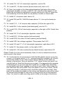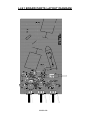
1
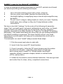
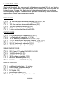
Laser Light Show Ramsey Electronics Model No. LLS1 Imagine creating your own laser light show at home using a kit that you built! Or connect the kit to your stereo and let the music change the patterns for you. You can do both with this safe and easy to build kit. • Easy to build and fun to play with. • Runs on 8-12VDC. • Motor speed controls to change pattern. • Audio mode modulates pattern to music. • Safe polycarbonate mirrors won’t break. LLS1• 1 PARTIAL LIST OF AVAILABLE KITS: RAMSEY TRANSMITTER KITS • FM10A, FM25B FM Stereo Transmitters • AM1, AM25 Transmitter RAMSEY RECEIVER KITS • FR1 FM Broadcast Receiver • AR1 Aircraft Band Receiver • SR2 Shortwave Receiver • AA7 Active Antenna • SC1 Shortwave Converter RAMSEY HOBBY KITS • SG7 Personal Speed Radar • SS70A Speech Scrambler/ Descrambler • TT1 Telephone Recorder • SP1 Speakerphone • MD3 Microwave Motion Detector • PH14 Peak hold Meter • LC1 Inductance-Capacitance Meter RAMSEY AMATEUR RADIO KITS • HR Series HF All Mode Receivers • DDF1 Doppler Direction Finder Kit • QRP Series HF CW Transmitters • CW7 CW Keyer • QRP Power Amplifiers RAMSEY MINI-KITS Many other kits are available for hobby, school, scouts and just plain FUN. New kits are always under development. Write or call for our free Ramsey catalog. LLS1 Laser Light Show Ramsey Electronics publication No. LLS1 Rev. 1.1a September 2003 COPYRIGHT ©2003 by Ramsey Electronics, Inc. 590 Fishers Station Drive, Victor, New York 14564. All rights reserved. No portion of this publication may be copied or duplicated without the written permission of Ramsey Electronics, Inc. Printed in the United States of America. LLS1• 2 Ramsey Publication No. LLS1 Manual Price Only $5.00 KIT ASSEMBLY AND INSTRUCTION MANUAL FOR Laser Light Show TABLE OF CONTENTS Introduction to the LLS1 .................................... 4 LLS1 Circuit Description ................................... 4 “Learn-As-You-Build” Kit Assembly ................... 5 Parts List ........................................................... 6 Assembly Steps ................................................. 8 LLS1 Parts Layout Diagram ............................. 10 LLS1 Schematic ............................................... 11 Setup and Testing ........................................... 16 Troubleshooting Guide ..................................... 17 Ramsey Kit Warranty ....................................... 19 RAMSEY ELECTRONICS, INC. 590 Fishers Station Drive Victor, New York 14564 Phone (585) 924-4560 Fax (585) 924-4555 www.ramseykits.com LLS1• 3 WARNING: This kit uses a CDRH class IIIa laser, which although not particularly dangerous, it is conceivable that it could cause eye damage under prolonged direct viewing. DO NOT STARE INTO THE BEAM. INTRODUCTION Now you can create your own laser light show at home! Your LLS1 will make different “spirograph” patterns on your wall. A laser beam is emitted from a laser pointer and bounces off two spinning mirrors and a mirror mounted to a speaker. The spinning mirrors bend the beam in circular motions to create the “spirograph” patterns. The mirror mounted on a speaker will vibrate to an audio source and cause the spirograph patterns to “jiggle” to the music. The motor speeds are adjustable to create different patterns and the speaker volume can be adjusted to give more or less audio modulation to the laser beam. LLS1 CIRCUIT DESCRIPTION The LLS1 can be broken up into 2 parts: the motor controls and the audio section. There are two motors, and each one has a controller. The controller is an oscillator circuit made with the timeless 555 timer. Refer to the schematic. As you can see there are two identical circuits at the top of the page. Each one has a 555 timer that pulses a power transistor. The power transistor then drives a motor. The power transistor is important because if the 555s were used to drive the motors directly, they would overheat. Potentiometers R1 and R2 adjust the duty cycle of the 555’s pulses and this changes the motor speed. At the bottom of the page is the audio amplifier that runs the LLS1’s speaker. Okay, let’s get building. LLS1• 4 RAMSEY Learn-As-You-Build KIT ASSEMBLY In order to make good solder connections on the LLS1 printed circuit board you should practice good soldering techniques. • • • • Use a 25-watt soldering pencil with a clean, sharp tip. Use only rosin-core solder intended for electronics use. Use bright lighting; a magnifying lamp or bench-style magnifier may be helpful. Do your work in stages, taking breaks to check your work. Carefully brush away wire cuttings so they don't lodge between solder connections. We have a two-fold "strategy" for the order of the following kit assembly steps. First, we install parts in physical relationship to each other, so there's minimal chance of inserting wires into wrong holes. Second, whenever possible, we install in an order that fits our "Learn-As-You Build" Kit building philosophy. This entails describing the circuit that you are building instead of just blindly installing components. We hope that this will not only make assembly of our kits easier, but help you to understand the circuit you’re constructing. For each part, our word "Install" always means these steps: 1. Pick the correct part value to start with. 2. Insert it into the correct PC board location. 3. Orient it correctly, follow the PC board drawing and the written directions for all parts - especially when there's a right way and a wrong way to solder it in. (Diode bands, electrolytic capacitor polarity, transistor shapes, dotted or notched ends of IC's, and so forth.) 4. Solder all connections unless directed otherwise. Use enough heat and solder flow for clean, shiny, completed connections. LLS1• 5 LLS1 PARTS LIST Sort and “check off” the components in the boxes provided. We do our best to pack all our kits correctly but it is possible that a mistake has occurred and we missed a part. Please note that physical descriptions of parts are for those currently being shipped. Sometimes the parts in your kit may have a different appearance but still have the same values. RESISTORS 4 2 1 2 1 1 1K ohm resistors [brown-black-red] (R5,R6,R7,R8) 22 ohm resistors [red-red-black] (R10,R11) 100 ohm resistor [brown-black-brown] (R4) 10K ohm potentiometers (R1,R2) 100K ohm potentiometer (R3) 2 ohm resistor [red-black-gold] (R9) CAPACITORS 2 2 4 1 1 1 1 0.47 uF electrolytic capacitors (C2, C3) 1 uF electrolytic capacitor (C1,C4) 10 uF electrolytic capacitor (C5,C6,C7,C8) .01 uF ceramic disk capacitor [marked 103] (C10) .1 uF ceramic disk capacitor [marked 104] (C11) 220 uF electrolytic capacitor (C12) 470 uF electrolytic capacitor (C9) SEMICONDUCTORS 2 2 2 1 1 2 555 Timer IC [marked NE555N] (U1,U2) 1N4002 diode (D4,D5) 1N4148 diode (D2,D3) 7805 voltage regulator (VR1) LM386N audio amplifier (U3) BS170 power MOSFET (Q1,Q2) MISCELLANEOUS 1 1 1 1 1 1 red/black twisted wire, 15 inches 22AWG wire, approximately 4 ft power jack (J1) RCA jack (J2) pushbutton switch (S1) length of double sticky foam tape 2” LLS1• 6 2 1 2 1 1 4 2 dc motors 8 ohm speaker big mirrors small mirror foam piece rubber feet nylon cable ties LLS1• 7 LLS1 PC BOARD ASSEMBLY STEPS 1. Take a look at the layout diagram. Let’s start with the bottom part of the board where all the circuitry is first, before moving on to the motors and mirrors. Install J2, the RCA jack at the bottom left of the board. 2. Next, install C9, 470 uF electrolytic capacitor next to J2. Watch the polarity. Make sure the lead soldered next to the “+” is not marked with a “-” band. 3. Install C5, 10 uF electrolytic capacitor, between J2 and C9. Watch polarity. 4. Install U3, LM386 audio amplifier [marked LM386N], above C9. Be sure the notch at one end of the IC lines up with the notch on the board drawing. 5. Install C10, .01 uF ceramic disk capacitor [marked 103], right of C9. 6. Install C4, 1 uF electrolytic capacitor, next to C9. Watch that polarity! 7. Install Q2, BS170 power MOSFET, [marked BS170], next to C10. Be sure they go in the right way. The flat side of the transistor should line up with the flat side of the drawing (facing C10). 8. Install U2, a 555 timer IC to the right of Q2. Make sure it goes in the right way, following the dotted or notched end of the part and the silkscreen or parts layout diagram. The dot or notch indicates pin 1. 9. Install D2, 1N4148 diode [ glass package] next to C4. Make sure the band on it lines up with the band on the board layout. 10. Install R6, 1K ohm resistor [brown-black-red]. 11. Install C3, 0.47 uF electrolytic capacitor, above U2. Watch polarity. 12. Install R8, 1K ohm resistor [brown-black-red], just to the right of U2. 13. Install C1, 1 uF capacitor, to the right of R8. 14. Install Q1, the other BS170 power MOSFET, above C1. Make sure it goes in the right way, flat side facing R8. 15. Install R5, 1K ohm resistor [brown-black-red], above Q1. 16. Install D3, 1N4148 [glass package], next to C1. Line up the band with the band on the board drawing. 17. Install U1, the second 555 timer [marked LM555N], right above D3. LLS1• 8 18. Install C2, 0.47 uF electrolytic capacitor, next to R5. 19. Install R7, 1K ohm resistor [brown-black-red], next to U1. 20. Now, lets solder in the three potentiometers that adjust the motor speed and amplifier volume. Install R1, R2, and R3 at the bottom of the board. Be sure they’re positioned correctly and flush to the PC board before soldering. Don’t be afraid to use plenty of solder on those tabs. 21. Install J1, the power jack, above J2. 22. Install D4 and D5, 1N4002 diodes above J1. Line up the bands as usual. 23. Install C11, .1 uF ceramic disk capacitor [104] to the right of D4. 24. Install R9, 2 ohm resistor [red-black-gold], next to C11. 25. Install C12, 220 uF electrolytic capacitor to the right of R9. Watch that polarity. 26. Install C8, 10 uF electrolytic capacitor under C12. 27. Install R11, 22 ohm resistor [red-red-black]. 28. Install R10, the other 22 ohm resistor [red-red-black]. 29. Install VR1 the voltage regulator. This powers the LLS1. 30. Install C6 and C7, 10 uF electrolytic capacitors, right above VR1. 31. Install S1, the power switch, to the right of VR1. 32. Install R4, 100 ohm resistor [brown-black-brown], right above C6. Whew! That’s it for the circuit assembly. Now, it’s time to attach the motors and mirrors to the board. 33. You’ll need to cut some wire to hold the little plastic mirrors on to the motors. Cut a piece about 2 1/4” long and strip the insulation off. Wind it around the shaft of one of the motors, about halfway on the shaft, as shown in the picture. Now cut another 2 1/4” piece of wire and wind it as you did before. Note that the picture on page 12 exaggerates the spacing of the wire just so you can see how it goes on. In reality they should be wound tightly and close together or on top of each other. Now solder the two coils onto the motor shaft. Don’t be afraid to use a lot of heat. These motors are tough. It will take a bit to melt the solder onto the shaft. Now peel off the protective plastic on the mirror and bend the ends of the wires up and around the edge of the mirror so they hold it like a four-fingered claw. You want to make sure they pinch a little at the edge of the mirror, LLS1• 9 LLS1 BOARD PARTS LAYOUT DIAGRAM LLS1• 10 LLS1 MAIN BOARD SCHEMATIC LLS1• 11 Pinch Solder Top View Speaker goes here Foam under here Solder wire from alligator clip Solder wire from spring LLS1• 12 so it is held securely. Remember, the mirrors are made out of polycarbonate; they won’t break. 34. Now, attach the small mirror to the other motor in the same way, except the two wire lengths are shorter: 1 3/4” each. 35. Now you need to solder on power wires for the motors and speaker. Cut the red/black wire into thirds. Strip the ends and solder them onto the motor and speaker tabs. It doesn’t matter which tab gets black or red wire. 36. It is time to mount the motors to the board. Take the foam and cut it into three equal size rectangles. Put two of the foam pieces on top of each other on the board in the silkscreened box towards the center (next to the outline for the laser pointer) and put the motor with the big mirror on top of the foam pieces on the outline. 37. Cut two lengths of wire, each about 4” long. Strip the ends and solder them on either side of the motor to hold it snugly down. Push down on the motor a little when you solder the wires so the foam is compressed just a little bit. This will ensure a snug fit. You can do this by soldering in the wires on one side of the motor, pushing down the motor a little, then soldering in the wires on the other side. You’ll want this motor to point slightly downward toward the other motor. 38. Solder down the other motor in the same way, except with no foam underneath, and cut the wires to 3 1/4” long. 39. The last part to be mounted is the speaker. The speaker goes in the upper left hand corner of the board. 40. The speaker sits upright with the edge of its magnet touching the rectangle on the board, and the edge of the cone touching the single line on the board. To secure the speaker so that it does not move use two pieces of double sticky foam tape (cut your included foam tape into three pieces; two for this step and a smaller piece the mirror you’re going to mount to the speaker). Stick one under the edge of the speaker cone and one under the edge of the magnet. This allows the speaker to be held in place but also allows you to tweak its position when you’re using the audio mode. 41. You now need to solder the power wires on the speaker and two motors down to the board. The wires from the motor with the big mirror go into pads P2 and P1. The power wires on the motor with the small mirror go into pads P3 and P4. The speaker wires go into pads P5 and P6. For all of these, it doesn’t matter which color wire goes in what hole. The color coding is there so you can switch them later if you want to reverse the motor directions. LLS1• 13 42. Soldering in the laser power wires is a little trickier. Unscrew the back of the pointer where the batteries go. You need to solder a wire on the spring in there. Cut a length of wire about 1 1/2 inches long. Strip both ends. Make a little hook on one end and hook it onto the spring inside the pointer. Reach your soldering iron in there and solder it. Be careful not to touch anything other than the spring with the soldering iron, otherwise meltage and burnage may occur (bad). Now solder the other end of the wire into the pad shown in the picture on the previous pages. DO NOT follow the silkscreen on the board or the parts layout diagram for this step; the silkscreen is incorrect. You must follow the diagram on page 12 for correct placement of the wires. Take the alligator clip and strip the end of the wire. Solder it into the pad shown in the same picture. Clip the clip end onto the laser pointer tube where the threads are. The body of the laser pointer is tied to +5 volts and the spring is ground. 43. There’s one last issue with the laser pointer. The power button is a momentary switch, so you will probably want a way to make it stay on for your light show. The best way is to take the included cable tie and cut a little piece, about 1/2” inch off the end. Put this on the button and attach the cable tie around the body of the laser pointer, over the button and the little cable tie cutoff piece. This should keep the button pressed so when you turn your kit’s power on the laser will always be on. Tape under speaker edge LLS1• 14 44. Now take two of the cable ties and the last piece of foam. Place the foam on the outline and use the cable ties to hold it down tight to the PC board. 45. The last thing to attach are the rubber feet. Note the 4 large holes near the motor/laser pointer/speaker section of the PC board; this is where the rubber feet should be stuck. In at least one place you may have to stick a foot over a couple of solder joints but that shouldn’t be a problem. Okay, enough of all of this stuff. Let’s turn it on! Power button Cable tie cutoff LLS1• 15 SETUP AND TESTING Plug in an 8-12V DC power supply into jack J1. Turn the kit on by pressing switch S1. Turn R1 and R2 up and down to vary the motor speed. Now that your laser is on and your motors are spinning, it’s time to adjust the mirrors. You just want to make sure that the laser beam hits the little mirror, then bounces off the bigger mirror on the other motor. You want to make sure that the light falls as completely on the mirrors as possible and doesn’t go off an edge. If it does your laser patterns will have a missing chunk. You can adjust the mirrors by turning and sliding the motors around a bit, and moving them towards and away from each other slightly. It may be necessary to unsolder the wires holding them to move them around. Once you get the two motor mirrors adjusted right, you need to stick the last big mirror onto the speaker cone. This is done with good ol’ double stick foam tape. Cut the remaining piece into two little pieces and stick them on the back of the mirror as shown. Now LIGHTLY put the mirror on the speaker roughly where it is in the picture. The point here is that the laser light hits the mirror after it bounces off the second motor. You need to have your kit turned on with laser shining and motors running so you can tell when the speaker mirror is aligned properly. When you are sure you’ve got it right, push the mirror down a little more firmly so it stays. If you need to readjust it later just be careful to SLOWLY remove it so it doesn’t tear off the speaker cone. When everything is cool, you should get a spirograph pattern on the wall that changes with motor speed. You can now plug a line level audio source into the RCA jack and the speaker will vibrate to the music, causing the mirror to jiggle and shake up the spirograph pattern. If everything is not cool, then I, the kit manual author, will rescue you in the next Little pieces of double stick tape section. LLS1• 16 TROUBLESHOOTING GUIDE Okay, let’s get the easy stuff out of the way first. If a motor isn’t spinning, check the 555 timers and make sure they are in the right way. Next check transistors and diodes for proper orientation. Lastly, check the electrolytic caps. If the laser isn’t on make sure you soldered that spring connection well, then push on the laser pointer button to make sure the cable tie is pushing the switch hard enough. If it isn’t, tighten it up or fiddle with it until it pushes the button down well. Adjusting the mirrors is the tricky part of the kit. The two motors are the easiest and should be done first. After that the speaker mirror has to be adjusted. I find that the mirror sits a little higher than center and hangs off the speaker cone a little more than 1/8” inch. The important thing is that when the laser is running and the motors spinning, you can see the laser pattern on the speaker mirror and none of it hangs off. Note, do not direct the laser right into your eye as you adjust it. CONCLUSION We sincerely hope that you will enjoy the use of this Ramsey product. As always, we have tried to compose our manual in the easiest, most “user friendly” format that is possible. As our customers, we value your opinions, comments, and additions that you would like to see in future publications. Please submit comments or ideas to: Ramsey Electronics Inc. Attn. Hobby Kit Department 590 Fishers Station Drive Victor, NY 14564 or email us at: [email protected] And once again, thanks from the folks at Ramsey! LLS1• 17 LLS1• 18 The Ramsey Kit Warranty Please read carefully BEFORE calling or writing in about your kit. Most problems can be solved without contacting the factory. Notice that this is not a "fine print" warranty. We want you to understand your rights and ours too! All Ramsey kits will work if assembled properly. The very fact that your kit includes this new manual is your assurance that a team of knowledgeable people have field-tested several "copies" of this kit straight from the Ramsey Inventory. If you need help, please read through your manual carefully, all information required to properly build and test your kit is contained within the pages! However, customer satisfaction is our goal, so in the event that you do have a problem, take note of the following. 1. DEFECTIVE PARTS: It's always easy to blame a part for a problem in your kit, Before you conclude that a part may be bad, thoroughly check your work. Today's semiconductors and passive components have reached incredibly high reliability levels, and its sad to say that our human construction skills have not! But on rare occasions a sour component can slip through. All our kit parts carry the Ramsey Electronics Warranty that they are free from defects for a full ninety (90) days from the date of purchase. Defective parts will be replaced promptly at our expense. If you suspect any part to be defective, please mail it to our factory for testing and replacement. Please send only the defective part (s), not the entire kit. The part(s) MUST be returned to us in suitable condition for testing. Please be aware that testing can usually determine if the part was truly defective or damaged by assembly or usage. Don't be afraid of telling us that you 'blew-it', we're all human and in most cases, replacement parts are very reasonably priced. 2. MISSING PARTS: Before assuming a part value is incorrect, check the parts listing carefully to see if it is a critical value such as a specific coil or IC, or whether a RANGE of values is suitable (such as "100 to 500 uF"). Often times, common sense will solve a mysterious missing part problem. If you're missing five 10K ohm resistors and received five extra 1K resistors, you can pretty much be assured that the '1K ohm' resistors are actually the 'missing' 10 K parts ("Hum-m-m, I guess the 'red' band really does look orange!") Ramsey Electronics project kits are packed with pride in the USA. If you believe we packed an incorrect part or omitted a part clearly indicated in your assembly manual as supplied with the basic kit by Ramsey, please write or call us with information on the part you need and proof of kit purchase. 3. FACTORY REPAIR OF ASSEMBLED KITS: To qualify for Ramsey Electronics factory repair, kits MUST: 1. NOT be assembled with acid core solder or flux. 2. NOT be modified in any manner. 3. BE returned in fully-assembled form, not partially assembled. 4. BE accompanied by the proper repair fee. No repair will be undertaken until we have received the MINIMUM repair fee (1/2 hour labor) of $18.00, or authorization to charge it to your credit card account. 5. INCLUDE a description of the problem and legible return address. DO NOT send a separate letter; include all correspondence with the unit. Please do not include your own hardware such as nonRamsey cabinets, knobs, cables, external battery packs and the like. Ramsey Electronics, Inc., reserves the right to refuse repair on ANY item in which we find excessive problems or damage due to construction methods. To assist customers in such situations, Ramsey Electronics, Inc., reserves the right to solve their needs on a case-by-case basis. The repair is $36.00 per hour, regardless of the cost of the kit. Please understand that our technicians are not volunteers and that set-up, testing, diagnosis, repair and repacking and paperwork can take nearly an hour of paid employee time on even a simple kit. Of course, if we find that a part was defective in manufacture, there will be no charge to repair your kit (But please realize that our technicians know the difference between a defective part and parts burned out or damaged through improper use or assembly). 4. REFUNDS: You are given ten (10) days to examine our products. If you are not satisfied, you may return your unassembled kit with all the parts and instructions and proof of purchase to the factory for a full refund. The return package should be packed securely. Insurance is recommended. Please do not cause needless delays, read all information carefully. LLS1• 19 TABLE OF CONTENTS Introduction to the LLS1 .................................... 4 LLS1 Circuit Description.................................... 4 “Learn-As-You-Build” Kit Assembly.................... 5 Parts List ........................................................... 6 Assembly Steps ................................................. 8 LLS1 Parts Layout Diagram ............................. 10 LLS1 Schematic ............................................... 11 Setup and Testing ........................................... 16 Troubleshooting Guide ..................................... 17 Ramsey Kit Warranty ....................................... 19 REQUIRED TOOLS • Soldering Iron (WLC100) • Thin Rosin Core Solder (RTS12) • Needle Nose Pliers (MPP4 or RTS05) • Small Diagonal Cutters (RTS04) ADDITIONAL SUGGESTED ITEMS • Helping Hands Holder for PC Board/Parts (HH3) • Technician’s Tool Kit (TK405) • Desoldering Braid (RTS08) Manual Price Only: $5.00 Ramsey Publication No. LLS1 Assembly and Instruction manual for: RAMSEY MODEL NO. LLS1 Laser Light Show. RAMSEY ELECTRONICS, INC. 590 Fishers Station Drive Victor, New York 14564 Phone (585) 924-4560 Fax (585) 924-4555 LLS1• 20 www.ramseykits.com TOTAL SOLDER POINTS 123 ESTIMATED ASSEMBLY TIME Beginner .............. 2 hrs Intermediate ........ 1 hrs Advanced ............. .30 min