1
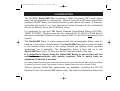
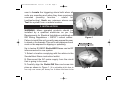
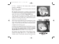
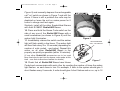
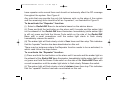
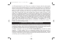
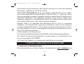
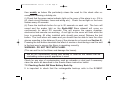
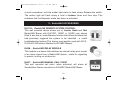
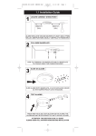
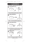
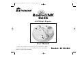
B16014-R0-Ei168RC-U&C
25/7/07
1:13 PM
Page 1
BASE
with Multiple Repeater
User Manual
Contains vital information on the products operation and installation. Read
and retain carefully. If you are just installing this product the manual
MUST be given to the householder.
Model: Ei168RC
B16014-R0-Ei168RC-U&C
25/7/07
1:13 PM
Page 2
CONTENTS
Page
1.
QUICK INSTALLATION GUIDE
3
2.
INTRODUCTION
4
3.
INSTALLATION
5
4.
THE “REPEATER” FUNCTION
10
5.
TROUBLESHOOTING THE RF LINK
12
6.
LIMITATIONS OF RADIO COMMUNICATIONS
13
7.
CHECKING & MAINTAINING YOUR SMOKE ALARM SYSTEM
14
8.
GETTING YOUR RadioLINK BASE SERVICED
17
9.
FIVE YEAR GUARANTEE
17
10.
TECHNICAL SPECIFICATION
18
11.
RadioLINK ACCESSORIES
21
2
B16014-R0-Ei168RC-U&C
25/7/07
1:13 PM
Page 3
1. QUICK INSTALLATION GUIDE
For use only with Ei Electronics Easi-fit Mains Powered Smoke & Heat Alarms. The
Ei168RC RadioLINK Base must be installed by a qualified electrician.
1.1) Install each RadioLINK Base in the centre of the ceiling at
least 0.30m from light fittings (as per the smoke/heat alarm
instructions) and connect to nearest mains circuit (see page 3).
1.2) Slide alarm on to the Ei168RC RadioLINK Base. This will
automatically activate the rechargeable back-up cells in the base.
Repeat this procedure for all alarms in the system (see page 5).
1.3) To House Code, insert a small screwdriver into the House
Code switch slot of each unit in succession. This must be
completed as quickly as possible (within 15 minutes) to activate
the House Code mode and ensure the system only
communicates with itself and not neighbouring systems (see
page 6). It is essential that the RadioLINK Bases are House
Coded.
1.4) Button test each alarm to ensure that they are all
communicating.
This guide is for quick referencing only. You must read the user manual thoroughly before
installation and use.
3
B16014-R0-Ei168RC-U&C
25/7/07
1:13 PM
Page 4
2. INTRODUCTION
The Ei168RC RadioLINK Base transmits a Radio Frequency (RF) alarm signal
when the unit attached to it senses fire. When it receives an RF alarm signal from
another Ei168RC Base, the attached smoke or heat alarm will sound. It therefore
eliminates the need to run long interconnect wires between all the smoke/heat
alarms on different floors and in different rooms.
It is designed for use with ‘RC’ Mains Powered Smoke/Heat Alarms (Ei161RC,
164RC & 166RC). The base can also be used with Ei141, Ei144 & Ei146 Easi-fit
alarms provided that a Remote Control device (Ei410 or Ei411H) is not used in the
system.
The RadioLINK Base, is mains powered and has rechargeable lithium cells for
back-up in the event of mains failure. The RadioLINK Base will normally be wired
to the nearest mains circuit in the ceiling (usually the lighting circuit, provided
unswitched live is available). The Smoke/Heat Alarm is then slid on to the
RadioLINK Base. Up to 12 units can be RF interconnected in this way.
It is essential to House Code the RadioLINK Bases to ensure they will not
accidently communicate with nearby systems. This is easily done as
explained in Section 3 overleaf.
(As a safety feature the units will all communicate with each other (provided they are within range) as installed
i.e. without any House Coding. The repeater function is disabled when units are not House Coded).
Various optional RadioLINK accessories are available, including the Ei411H
Remote Control (for use with ‘RC’ alarms only). This wall-mounted device allows the
4
B16014-R0-Ei168RC-U&C
25/7/07
1:13 PM
Page 5
user to Locate the triggering alarm both when all
units are sounding and when they have previously
sounded (memory function - useful for
troubleshooting), Hush any nuisance alarms and
Test the system from a remote location.
3. INSTALLATION
WARNING: Mains operated products should be
installed by a qualified electrician as per the
Requirements for Electrical Installations published as
IEE Wiring Regulations – BS7671 current edition.
Failure to install this unit correctly may expose the user
to shock or fire hazards.This unit is not waterproof and
must not be exposed to dripping or splashing.
Figure 1
Up to twelve Ei168RC RadioLINK Bases can be RF
interconnected in one system.
1. Select a location complying with the advice in the
Smoke/Heat Alarm instruction leaflet.
2. Disconnect the AC mains supply from the circuit
that is going to be used.
3. Carefully align the RadioLINK Base and screw into
place as shown in Figure 1. (It is advisable at this time to
use only one screw (as shown) as it allows the base to be
5
Figure 2
B16014-R0-Ei168RC-U&C
25/7/07
1:13 PM
Page 6
rotated later if required. If you use only one screw,
ensure the base is secure on the ceiling before
proceeding further with the installation. Remember to
complete the installation by securing with the second
screw after the system has been checked).
4. Lift off the wiring cover as shown in Figure 2.
5. If the mains wires are recessed (coming
through a hole in the ceiling), bring the wires
to the terminal block through the rear hole in
the mounting plate as shown in Figure 3.
REMOVEABLE
TRUNKING DOOR FOR
Figure 3
Ensure the rear foam gasket seals around the edge of the hole in the ceiling. This
is to prevent air draughts affecting the smoke or heat entering the alarm. If the hole
is too large it should be sealed with silicone rubber or equivalent (when the rest of
the installation is complete).
If the mains wires are being brought along the surface:
(a) position the mounting plate so the cable trunking is as shown in Figure 3.
(b) Carefully cut and trim the knockouts in the RadioLINK Base side walls to blend
with the contours of the trunking.
Important: Only cut the thinned down knockout section and leave the top intact as
shown. There is only one position suitable for the surface wiring to enter the alarm.
6. The house wiring must then be connected to the terminal block on the Ei168RC
RadioLINK Base as follows (see Figure 3):
6
B16014-R0-Ei168RC-U&C
25/7/07
1:13 PM
Page 7
L: Live - connect to the house wires coloured
brown, or marked L.
N: Neutral - connect to the house wires coloured
blue, or marked N.
IC: (Hardwire Interconnect- normally not used except
to hardwire interconnect to mains Smoke/Heat Alarms
which don't have an Ei168RC RadioLINK Base)
The alarm does not need to be earthed. However the
earth terminal is provided for the convenience of the
installers so that any earth wire or cable coloured green
& yellow, can be safety terminated.
Figure 4
Note: House wiring should not be “bunched up” in the
area of the alarms but quickly and neatly directed
away. This will minimize their effect on the radio aerial.
7. Replace the wiring cover.
8. Remove the required Smoke/ Heat Alarm from the
box (discard the mounting plate supplied). Carefully
line up the Smoke/Heat Alarm on the Ei168RC
RadioLINK Base and slide it on (see Figure 4).
9. Connect the mains power to the alarm circuit.
Check the green light is on. If the amber light
flashes every 10 seconds, remove the alarm (see
7
Figure 5
B16014-R0-Ei168RC-U&C
25/7/07
1:13 PM
Page 8
Figure 5) and manually depress the rechargeable
cell "on" switch as shown in Figure 7 and refit the
alarm. If there is still a problem the cells may be
depleted so leave the unit on mains power for 2
hours to charge and test again.
Similarly, install all the other Smoke/Heat Alarms
with their Ei168RC RadioLINK Bases.
10. Press and hold the House Code switch on the
side of any one of the RadioLINK Bases with a
small screwdriver (as shown in Figure 6) until the
amber light illuminates.
11. Immediately release the switch and the amber
light will flash quickly a few times. The amber light
will then flash every 5 or 10 seconds (depending on
number of units coded - see below). Repeat this
action on all other RadioLINK Bases in the
property as quickly as possible (within 15 minutes).
(If any other RadioLINK accessories are to be used
they must also be put into the house code mode at this
time – see their instructions leaflets for details).
Figure 6
RECHARGEABLE
CELL "ON" SWITCH
Figure 7
12. Check that all RadioLINK Bases have House
Coded and communicate with each other by counting the number of times the amber
light flashes on each base in turn. For example, 3 units in the system should give 3
short flashes every 5 seconds, 4 units should give 4 short flashes and so on, up to 12
8
B16014-R0-Ei168RC-U&C
25/7/07
1:13 PM
Page 9
units. There is a long flash at 10 units to make counting easier and a further long flash
at 20 units (e.g. for systems of 12 Ei168RC Bases and 8 other RadioLINK devices such
as Ei407 Manual Call Point and/or Ei411H Remote Control Switch). After 12 units, the
flashes are shown every 10 seconds. For example, with 13 units in the system there
should be 9 short flashes + 1 long flash + 3 short flashes, every 10 seconds. It may take
up to 30 minutes for all the units in the system to be House Coded correctly. If at the
end of this period certain units do not show the correct number of flashes, repeat the
process (from point 10 above) once more and if this fails see Section 5.
13. The units will automatically exit the House Code learn mode after 30 minutes
however we recommend that you manually exit the House Code mode by repressing and holding the House Code switch on one of the units in the system until the
amber light turns on, then release. The amber light should stop flashing and an 'exit
House Code' signal will be sent to all other units. Check that the amber lights on all other
units have stopped flashing. (If some units are still flashing it may indicate a problem
with the radio communication from this unit to the other units). Repeat the process once
more and if this fails see Section 5. Manually exiting the House Code mode reduces the
risk of accidentally House Coding your RadioLINK Bases with nearby systems.
14. Check the communication by pressing the test/hush button for up to 20 seconds
on each unit in turn. The alarm will sound and the amber light on the RadioLINK Base
sidewall will illuminate continuously for around 3.5 seconds. All other alarms should
sound (this may take up to 20 seconds as the message may need to be relayed
through repeaters). Release the test button. The local alarm will cease and you should
then be able to hear the other alarms sounding in the distance and then stopping. This
may take up to 20 seconds (if any of the alarms do not sound, see Section 5).
9
B16014-R0-Ei168RC-U&C
25/7/07
1:13 PM
Page 10
When button testing units in sequence it is important to wait 15 seconds plus a further
6 seconds per repeater between button tests (e.g. for a system with 10 repeaters,
time to wait: 15 seconds + 10 x 6 seconds = 75 seconds between button tests).
Finally attach the label provided to the distribution board to identify the alarm circuits.
(Note: To clear House Codes see section 10 - Technical Specification)
4. THE “REPEATER” FUNCTION
All Ei168RC Bases are set as “Repeater” Bases
as supplied. The function of a Repeater Base is
to receive and then re-transmit the RF signals.
This provides multiple signal paths throughout
the installation to give improved RF signal
reliability (with 3 or more RadioLINK Bases).
Note the “Repeater” function is not operational
until all the units are put in to House Code mode.
Figure 8
The operation of the “Repeaters” can be
observed as each unit turns on its amber light as
a RadioLINK message is being repeated.
A maximum of ten RadioLINK Bases can be set
as ‘“repeaters” in any one system. If more than
ten units are being installed, some of the units
in the system must have their “repeater” mode
de-activated. The units to de-activate should
10
Figure 9
B16014-R0-Ei168RC-U&C
25/7/07
1:13 PM
Page 11
have repeater units around them and should not adversely affect the RF coverage
throughout the system. See Figure 8.
Any units that may provide the only link between units on the edge of the system
and the remaining units should be left as “repeaters”, as illustrated in Figure 9.
To de-activate the “Repeater” function:
(i) Select a RadioLINK Base to de-activate based on the advice above.
(ii) Press and hold the test button on the alarm until it sounds and the amber light
on the sidewall of the RadioLINK base illuminates. Immediately (while amber light
is still on) press and hold the House Code switch on the side of the RadioLINK
Base with a small screwdriver until the amber light starts to flash slowly.
Immediately release the switch.
(iii) The amber light will flash slowly a total of four times and then stop. This indicates
that the “repeater” function has been deactivated on this unit.
There may be instances where the Repeater function needs to be re-activated, in
which case follow the steps below.
To re-activate the “Repeater” function:
(i) Press and hold the test button on the alarm until it sounds and the amber light on
the sidewall of the RadioLINK base illuminates. Immediately (while amber light is still
on) press and hold the House Code switch on the side of the RadioLINK Base with
a small screwdriver until the amber light starts to flash slowly. Release the switch.
(ii) The amber light will flash slowly a total of sixteen times then stop. This indicates
that the “repeater” function has been re-activated on this unit.
11
B16014-R0-Ei168RC-U&C
25/7/07
1:13 PM
Page 12
5. TROUBLESHOOTING THE RF LINK
If when checking the RadioLINK interconnection some of the alarms do not
respond to the button test, then:
(i) Ensure you have held the test button down for up to 20 seconds and the amber
light has come on continuously for 3.5 seconds.
(ii) If you have de-activated the Repeater function on a unit, try re-activating the
Repeater on this unit and de-activating a different unit.
(iii) Extend the flexible antenna from the base housing. To do this, the antenna
should first be removed from its groove in the base of the unit (see Figure 10).
Remove the breakaway section in the outer rim and push the antenna in to this
groove. For improved signal strength the antenna can be pushed flat or vertical with
respect to the ceiling (see Figure 11).
Figure 10
Figure 11
12
B16014-R0-Ei168RC-U&C
25/7/07
1:13 PM
Page 13
(iv) Re-locate/rotate the units. There are a number of reasons why the radio signals
may not reach all the smoke alarms in your system (see Section 6 on “Limitations of
Radio Communications”). Try rotating the units or re-locating the units (e.g. move them
away from metal surfaces or wiring) as this can significantly improve signal reception.
Rotating and/or relocating the units may move them out of the range of existing
units even though they may have already been House Coded correctly in the
system. It is important therefore to check that all detectors are communicating in
their final installed positions. If units are rotated and/or resited, we recommend that
all units are returned to the factory settings (press and hold the House Code switch
on for around 6 seconds until the amber light comes on solidly and then flashes
rapidly and stops. Release the House Code switch). Then House Code all units
again in their final positions as per Section 3 “Installation” paragraphs 10 - 13. The
RadioLINK interconnection should then be checked by counting the number of
flashes and button testing all units.
6. LIMITATIONS OF RADIO COMMUNICATIONS
Ei Electronics radio communication systems are very reliable and are tested to high
standards. However, due to their low transmitting power and limited range (required
by regulatory bodies) there are some limitations to be considered:
(i) Radio equipment, such as the Ei168RC RadioLINK Base, should be tested
regularly - at least weekly. This is to determine whether there are sources of
interference preventing communication. The radio paths may be disrupted by moving
furniture or renovations, and so regular testing will help identify these and other faults,
so that they can be rectified (see Section 5).
13
B16014-R0-Ei168RC-U&C
25/7/07
1:13 PM
Page 14
(ii) Receivers may be blocked by radio signals occurring on or near their operating
frequencies, regardless of the House Coding.
The Ei168RC RadioLINK Base has been tested to EN 300 220-1 V1.3.1 (200009) in accordance with the requirements of EN 300 220V1.1.1 (2000-09). These
tests are designed to provide reasonable protection against harmful interference in
residential installations. This equipment generates, uses and can radiate radio
frequency energy and, if not installed and used in accordance with the instructions,
may cause interference to radio and/or television reception.
However, there is no guarantee that interference will not occur in a particular
installation. If this device does cause such interference, which can be verified by
turning the RadioLINK device on and off (remove both the mains and turn off backup power supplies), the user is encouraged to eliminate the interference by one or
more of the following measures:
(i) Re-orientate or re-locate the unit.
(ii) Increase the distance between the Ei168RC and the device being affected.
(iii) Connect the device being affected to a mains outlet on a circuit different from
the one that supplies the Ei168RC.
(iv) Consult the supplier or an experienced radio/television technician.
7. CHECKING & MAINTAINING YOUR ALARM SYSTEM
7.1 Inspection & Testing Procedure
We recommend that your Alarm System is checked directly after installation and
14
B16014-R0-Ei168RC-U&C
25/7/07
1:13 PM
Page 15
then weekly as below. We particularly stress the need for this check after reoccupation following a holiday etc.
(i) Check that the green mains indicator light on the cover of the alarm is on (If it is
off, check circuit breakers, fuses and wiring etc.). Check the red light on the cover
flashes every 40 seconds.
(ii) Press the test/hush button for up to 20 seconds on each unit. The horn will
sound and the amber light on the RadioLINK Base sidewall will come on
continuously for about 3.5 seconds. This will ensure the sensor chamber,
electronics and sounder are working. A red light on the cover will flash while the
horn is sounding. All other installed units should now sound. Release the test
button. The local alarm will cease and you should then be able to hear the other
alarms sounding in the distance (if any of the alarms do not sound see Section 5).
Pressing the test button simulates the effect of smoke or heat during a real fire and
is the best way to ensure the Alarm is operating correctly.
WARNING: DO NOT TEST WITH FLAME.
(This can set fire to the Alarm and damage the house).
We do not recommend testing with smoke or heat as the results can be
misleading unless special apparatus is used.
Check for any sign of contamination such as cobwebs or dust and if necessary
clean the alarm as described in the Smoke Alarm instruction leaflet.
7.2 Checking RadioLINK Base Battery Back-Up
It is important to check that the rechargeable back-up cells in the Ei168RC
15
B16014-R0-Ei168RC-U&C
25/7/07
1:13 PM
Page 16
RadioLINK Base are switched on, charged, and capable of powering the system.
We therefore recommend that the functioning of the mains rechargeable cell backup is checked directly after installation and then at least yearly as follows:
(i) Check that the amber light on the side of the RadioLINK Base is not flashing
once every 10 seconds. If it is, it indicates that the rechargeable cells in the
RadioLINK Base are not connected or depleted. Remove the Alarm and press the
rechargeable cell “on” switch (see Figures 5 & 7). Re-install the Smoke/Heat Alarm
and re-connect the mains. If the amber light is still flashing every 10 seconds leave
it for 2 hours to charge and then re-check.
(ii) Switch off or disconnect mains. The green light on the Smoke/Heat Alarm will
turn off. Check the radio communication as described in Section 7.1. Check the
battery backup as per (i) above.
(iii) If everything is satisfactory, re-connect the mains.
If the interconnect fails to operate or the amber light continues to flash every 10
seconds (even after (i) previously) then it is defective and must be replaced (see
Section 8 “Getting your RadioLINK Base Serviced” below).
Further instructions are given in the instruction leaflet supplied with the Smoke/
Heat Alarm regarding their maintenance and checking of their back-up supplies.
7.3 End of Life
After 10 years (see date on the side of the RadioLINK Base) the Ei168RC
RadioLINK Base and the attached Smoke or Heat Alarm must be replaced.
16
B16014-R0-Ei168RC-U&C
25/7/07
1:13 PM
Page 17
8. GETTING YOUR RadioLINK BASE SERVICED
If your RadioLINK Base fails to work after you have carefully read all the instructions,
checked that the unit has been installed correctly and is receiving AC power (green light
on Smoke/Heat Alarms), contact Customer Assistance at the nearest address given at
the end of this leaflet. If it needs to be returned for repair or replacement, lightly press
the "off" switch (see Figure 7) to disconnect the rechargeable cells and put both the
alarm and the Ei168RC RadioLINK Base in a padded box and send it to "Customer
Assistance and Information" at the nearest address given on the unit or in this leaflet.
State the nature of the fault, where the RadioLINK Base and alarm were purchased and
the date of purchase. Do not snap the Smoke/Heat Alarm on to the RadioLINK Base as
this connects the battery and the unit may beep or alarm in the post.
9. FIVE YEAR GUARANTEE
Ei Electronics guarantees this RadioLINK Base for five years from date of
purchase against any defects that are due to faulty materials or workmanship. This
guarantee only applies to normal conditions of use and service and does not
include damage resulting from accident, neglect, misuse, unauthorised
dismantling, or contamination howsoever caused. This guarantee excludes
incidental and consequential damage. This guarantee does not cover costs
associated with the removal and/or installation of units. If this RadioLINK Base
should become defective within the guarantee period, it must be returned with proof
of purchase, carefully packaged, and with the problem clearly stated to one of the
addresses given at the end of this leaflet (see "Getting Your RadioLINK Base
Serviced"). We shall at our discretion repair or replace the faulty unit.
17
B16014-R0-Ei168RC-U&C
25/7/07
1:13 PM
Page 18
Do not interfere with the RadioLINK Base or attempt to tamper with it. This will
invalidate the guarantee, but more importantly may expose the user to shock or fire
hazards. This guarantee is in addition to your statutory rights as a consumer.
10. TECHNICAL SPECIFICATION
Mains: 230VAC
Battery Back-Up: Built-in Rechargeable Lithium Cells (up to 30 days back-up)
Approvals: Complies with EMC, Electrical Safety and Radio Regulations –
including requirements of the RTTE Directive Compatibility 1999/5/EC (RF
Performance to EN300220-3, EMC to EMC 301489-3) - independently tested
Humidity Range: 15% to 95% RH (non-condensing)
Radio Frequency: 868 MHz band
RF Power: +5dBm
Range: 150 meters (minimum) in free space (without use of the “Repeater” function)
RF RECEPTION
Alarm Signal Reception: Turns on horn without red light flashing for as long as it
receives an alarm signal. An alarm cancel signal turns off the alarm; if no cancel
signal is received it automatically turns off after 70 seconds
18
B16014-R0-Ei168RC-U&C
25/7/07
1:13 PM
Page 19
RF VISUAL INDICATOR (Amber)
On Transmission: Amber LED lights continuously for 1.5 to 3.5 seconds while
messages are being transmitted. The amber light also flashes after receipt of an
alarm cancel signal
Low Battery Indication: Amber light flashes every 10 seconds
Size of System: The recommended maximum is 12 Ei168RC units. In addition 8
further RadioLINK accessories (such as Ei407 Manual Call Point & Ei411H Remote
Control Switch) can be used. In some installations the RF range is likely to be the
limiting factor
Communication: All units will communicate together as shipped. After a unit has been
House Coded it will only communicate with other units House Coded at the same time.
House Coding is essential to prevent false alarms with, or from neighbouring systems.
The “Repeater” function will not operate until units have been House Coded
Entering House Code Mode: Pressing and holding the House Code switch until the
amber light illuminates, then releasing puts the RadioLINK Base into House Code mode.
House Code Mode: The RadioLINK Base transmits and receives specific codes.
The amber light will flash every 5 or 10 seconds (depending on number of units coded
- up to 12 units the flashes are every 5 seconds, above 12 units the flashes are every
10 seconds) to indicate the number of House Coded units in the system
Duration of House Code Mode: 30 minutes
19
B16014-R0-Ei168RC-U&C
25/7/07
1:13 PM
Page 20
Clearing House Codes: The House Codes memorised can be deleted (i.e. the
RadioLINK Bases can be uncoded) by pressing and holding the House Code
switch on for about 6 seconds. The amber light comes on solidly, then flashes
rapidly and stops. Release the House Code switch. The RadioLINK Base has now
been returned to the default factory setting.
All Ei168RC Bases are set as “Repeater” Bases as standard. The function of a
Repeater Base is to receive and then re-transmit the RF signals. This provides
multiple possible signal paths to give increased reliability. A maximum of ten
RadioLINK Bases can be set as Repeaters in any one system.
De-activating the Repeater function:
Press and hold the test button on the alarm until it sounds and the amber light on
the side of the RadioLINK base illuminates. Immediately (while amber light is still
on) press and hold the House Code switch on the side of the RadioLINK Base with
a small screwdriver until the amber light starts to flash slowly. Release the switch.
The amber light will flash slowly a total of four times and then stop. This indicates
that the Repeater mode has been deactivated.
Re-activating the Repeater function:
Press and hold the test button on the alarm until it sounds and the amber light on
the side of the RadioLINK base illuminates. Immediately (while amber light is still
on) press and hold the House Code switch on the side of the RadioLINK Base with
20
B16014-R0-Ei168RC-U&C
25/7/07
1:13 PM
Page 21
a small screwdriver until the amber light starts to flash slowly. Release the switch.
The amber light will flash slowly a total of sixteen times and then stop. This
indicates that the Repeater mode has been re-activated.
11. RadioLINK ACCESSORIES
Ei411H - RadioLINK REMOTE SYSTEM CONTROL
This wall mounted device allows you to Locate, Hush and Test
RadioLINK Bases with Ei161RC, 164RC or 166RC only alarms
fitted. It also has a Locate Memory function that allows the alarm that
had previously triggered the system to be identified - a useful
troubleshooting feature.(This device must not be used with Ei141,
Ei144 & Ei146 alarms attached to Ei168RC Bases).
Ei428 - RadioLINK RELAY MODULE
This module is a device that switches an internal relay upon receipt
of an alarm signal from a RadioLINK device - useful for signalling
to panels, turning on strobes etc.
Ei407 - RadioLINK MANUAL CALL POINT
This wall mounted call point, when activated, will alarm all
Smoke/Heat Alarms mounted on Ei168RC RadioLINK Bases.
21
B16014-R0-Ei168RC-U&C
25/7/07
1:13 PM
Page 22
The crossed out wheelie bin symbol that is on your
product indicates that this product should not be disposed
of via the normal household waste stream. Proper
disposal will prevent possible harm to the environment or
to human health. When disposing of this product please
separate it from other waste streams to ensure that it can
be recycled in an environmentally sound manner. For
more details on collection and proper disposal, please
contact your local government office or the retailer where
you purchased this product.
0889
22
B16014-R0-Ei168RC-U&C
25/7/07
1:13 PM
Page 23
23
B16014-R0-Ei168RC-U&C
25/7/07
1:13 PM
Page 24
Aico Ltd
Mile End Business Park,
Maesbury Road, Oswestry,
Shropshire SY10 8NN, U.K.
Telephone: 0870 7584000
www.aico.co.uk
Ei Electronics
Shannon Industrial Estate,
Shannon, Co. Clare, Ireland.
Telephone: +353 (0)61 471277
www.eielectronics.com
P/N B16014 Rev 0