1
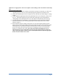
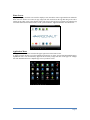
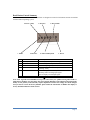
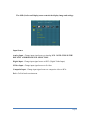
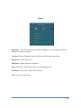
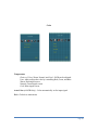
A615 Smart Multi Function Display Reference Guide Tel 951 813 3600 or 800 967 4287 · Fax 888 550 6578 · www.argonautcomputer TABLE OF CONTENTS Mounting, Wiring, Care Pages 1-2 Quick Start Page 3 Android Interface, Mouse Control Pages 4-6 Bezel Button Control Operation Pages 7-12 Troubleshooting Page 13 Warranty, Repair, Service Policy Pages 14-17 Specifications Pages 18 Your Argonaut A615 Smart Multi Function Display (SMFD) has been engineered for trouble-free use in the marine environment. Please retain this reference guide for relevant installation, wiring, care and operational information. Surface Mounting The A615 SMFD has been designed for an easy, secure and sealed installation. installations, please note the following steps: For surface mount 1) Locate a suitable installation mounting surface. The surface should be flat and allow at least enough room for the outside bezel face to fit (14.45” x 11.70” W x H). Note that the thickness of the display is 1.35” so make sure there is enough clearance to mount in your desired location. Make sure there is sufficient clearance behind the surface for cabling passage (.75” minimum recommended). Rear surface space should also allow clearance to install mounting screws from the rear; however, the display can be installed without using mounting screws, if necessary. 2) Once mounting location is identified, carefully align the mounting template to the surface in the exact location desired and secure lightly with tape. Mark the centers of the 4 VESA mount pattern holes. Mark the connector clamp bracket outline and outside edge of the template. Once all holes are marked, surface may be drilled and cut accordingly. 3) Display can now be seated against the surface. In some installations, a bead of marine caulking may be desired to help prevent any water intrusion to the mounting surface openings. This bead of caulking/adhesive can be placed upon the outer edge of the back cover and may also be sufficient to secure the display in place without screwing into the enclosure from behind the surface. Take care not to allow sealant to penetrate the gap between the front bezel and rear cover as this may prevent opening the display if service is ever needed. Another approach is to lay down a thin layer of weather stripping flush to the display edge. This strip can be sealed at the edges with caulking. In general, after positioning/sealing is complete, screw display down to surface (Note: screw type is M5 stainless steel machine thread). Different length screws may be required depending on bulkhead thickness. In all installations, where water contact can occur with the display, caulking sealant should be placed around the screw and connector clamp bracket openings. Once secured to the surface, take care not to over tighten mounting screws. Optional Flush Mount Kit The optional flush mount kit allows you to embed the display within the mounting surface completely flat to provide a “glass bridge” look. Included in the kit are rear mount plate, mounting screws, adjustment screws, oversize adhesive backed polycarbonate face plate, and mounting template. For flush mount installations, please note the following steps: 1) Locate a suitable installation mounting surface. The surface should be flat and allow at least enough room for the polycarbonate bezel face plate to fit (16.21” x 12.46” W x H). Note that the thickness of the display is 1.35” so make sure there is enough clearance to mount in your desired location. Add an additional depth of at least 6” for sufficient clearance behind the surface for cabling passage and to install mounting plate plus adjustment screws. 2) Once mounting location is identified, carefully align the mounting template to the surface in the exact location desired and secure lightly with tape. Mark the centers of the 8 mount pattern holes and the display cutout hole. Once all holes and cutout are marked, surface may be drilled and cut accordingly. Use the correct bit to allow pilot holes matching the M6 screw size. The flathead screws will need to be installed flush to the surface so cut an appropriate countersink into the surface. Take care not to make the screw passage holes too large or the countersinks too deep as this could compromise the mounting integrity. 3) Attach mount plate to the back of the A615 enclosure using four M5 screws and washers. 4) Carefully slide A615 bezel through display cutout hole such that back mounting plate makes contact with back of mounting surface. Place 8 M6 flathead screws through mounting holes and Page 1 attach to 8 corresponding mount plate holes. Tighten screws such that tips are about flush with the mount back edge surface (note: further adjustment tightening will be done in steps listed below). 5) Allow display assembly to drop back into cutout hole such that the screw heads are flush to the front mounting surface. Carefully tighten front surface screws an equal amount to pull display up to a perfectly aligned “flush position with outside front surface. 6) Screw 4 back adjustment screws against the back of the mounting surface to firmly secure the display in place. 7) Pull off adhesive liner from face plate and carefully attach to display front and surface opening. Optional RAM Or U-Bracket Mount The RAM mount includes surface base, swivel arm, display mounting base plate and screws/washers. Secure square display mounting base plate to back of display using four stainless steel 10/32 x ½” screws (in order from base, flat washer, split washer, screw). Note: RAM logo should be oriented upside down for optimal position. Securely tighten but do not over tighten. Attach circular RAM base to mounting location. Secure display with swivel arm to surface. U-Bracket mount includes 2 aluminum U brackets, and 2 adjustment/mounting knobs. Locate suitable mounting location for U bracket mount base. Attach base to mounting surface with 4 bolts and backing washers/nuts. Place display within mounted base bracket and secure with side knobs. Wiring NOTE: THE POSITIVE WIRE IS RED AND THE NEGATIVE WIRE IS BLACK. The standard input cables include 2 x USB, DVI, RCA/S-Video, and DC Power cable. If optionally equipped with HDMI, note that this is an HDMI output signal which will output a duplicate image of your Android screen. All cables exit the rear of the display through a waterproof cable clamp. Note that the cable ends are not waterproof and should be placed or installed in a dry, protected area. DO NOT PULL CABLES TIGHT TO PREVENT EXCESS STRAIN AND POSSIBLE BREAK IN CABLE CLAMP SEAL. Contact your Argonaut Dealer if additional cable lengths are required in excess of standard provided. Power The A615 SMFD is designed for 12 Volt power input through an Argonaut supplied power regulator. The correct regulator should be specified at time of ordering for connection to either a 12 volt or 24 volt system. The regulators accept a range of voltage (either 9 to 18V or 19 to 32V) and provide a steady 12 volts to the display. NOTE: ANY DIRECT CONNECTION OF THE DISPLAY TO 12 OR 24 VOLT POWER WITHOUT FIRST RUNNING THROUGH THE ARGONAUT SUPPLIED REGULATOR COULD PERMANENTLY DAMAGE THE DISPLAY AND VOID YOUR WARRANTY. DO NOT CONNECT THE REGULATOR TO VOLTAGE EXCEEDING THE SPECIFIED RANGE AS THIS WILL DAMAGE THE REGULATOR. DO NOT CONNECT THE DISPLAY DIRECTLY TO A/C POWER (110-220V) POWER AS THIS WILL DAMAGE THE DISPLAY AND COULD CAUSE A FIRE. PLEASE MAKE SURE TO AVOID IMPROPER CROSSING WIRES (POSITIVE TO NEGATIVE) AS THIS CAN DAMAGE THE DISPLAY ELECTRONICS. Care & Precautions Care: The LCD has an optically bonded anti-reflective glass overlay for optimal sunlight visibility. Clean with soft clean cloth dampened with fresh water to remove residue. Follow up with alcohol and lens cleaning wipes if desired. If water has collected in screen bezel, wipe dry before covering/storing. NOTE: DO NOT ALLOW SALT WATER DEPOSITS TO REMAIN ON GLASS SURFACE FOR EXTENDED PERIODS (REMOVE SALT DEPOSITS WITH FRESH WATER). LONG TERM SALT DEPOSITS MAY CAUSE PERMANENT DAMAGE TO THE SCREEN SURFACE. Additional Precautions: Do not operate in temperature extremes (below 32°F (0° C) or above 104 °F (40° C)). Do not put pressure or contact directly on screen surface. Do not connect directly to power source without using the regulator supplied. Do not reverse power wires. Do not expose to Page 2 submersion or high pressure water. Do not pull or strain cabling as this can break the cable clamp seal. Quick-Start Instructions 1.) Connect power as described in “Wiring” section below. Upon power connection, you will see the Argonaut logo boot screen for several seconds during boot up followed by the home screen. 2.) Connect the included optical mouse to navigate the screen and make any initial changes to settings or Apps. 3.) Connect additional signal input cables from signal output devices (for example PC, camera, black box, etc.). The default signal input is from the internal Android processor board and labeled “Analog Input” in the signal input menu screen. This input will automatically load on boot up. 4.) All android functions are controlled by external USB mouse or touch pad. Front bezel buttons control LCD functions such as switching signal inputs and dimming control (button control summary on page 7). 5.) Power down the system by clicking on the power icon. You can also put the display in power conserving sleep mode by pressing the physical power button (this turns off the LCD however the android processor will continue running in the background for instant access upon pressing the power button again). Disconnecting external power or flipping a breaker to the off position is another way to shut down the system. Note: Once powered down through power icon or disconnected power, the system will not restart by pressing the physical power button. In order to power up, either reconnect to power if already disconnected or flip the appropriate breaker switch to off then on to restart. Page 3 A615 Android Interface & Mouse Control The Argonaut A615 utilizes the Android Jelly Bean 4.2.2 operating system interface. It is recommended to connect the supplied optical mouse for initial system set up and configuration. The mouse will operate on screen in a very similar manner to a windows computer mouse. You will clearly see the mouse pointer on the screen and it will remain in its last position. Note the following basic mouse functions within Android: Standard 2 Button Mouse: 1.) A single left click upon any menu button or app icon will launch that function or app. 2.) A single left click and hold upon an app icon allows you to move or remove the target app. 3.) Rotating the scroll wheel up or down, swipes the home or apps menu screen left or right. Alternatively, a single left click and hold on the home screen or apps menu screen allows you to swipe left or right to alternate home or apps menu screen pages. 4.) A double click within certain apps will zoom in the image. It is recommended not to use this feature as certain apps will lock in the last zoom in setting and must be reset to erase stored app cache or data. For best zoom in/out capability, use apps that contain clickable +/- icons for zoom. Argonaut installed marine apps are all equipped with this function. 5.) A single right click acts like the back button and will return you to the previously displayed screen. OneTouch Pointer: 1.) A single tap upon any menu button or app icon will launch that function or app. 2.) A double tap and hold upon an app icon allows you to move or remove the target app. 3.) A double tap and hold on the home screen allows you to swipe left or right to alternate home screen pages. 4.) A double tap within certain apps will zoom in the image. 5.) A double tap and hold on certain apps will drag image (map, picture, webpage) left, right, up or down. 6.) A single right tap (top right corner) acts like the back button and will return you to the previously displayed screen. Status Bar The status bar will be visible at screen bottom while in any android screen. The icons listed from left to right include: Return: Left click once to return to the previous screen. Home: Left click once to return to the home screen. History: Lift click once to view currently accessed apps. Volume Down: Left click to reduce volume. Volume Up: Left click to increase volume. Power: Left click once to access power down confirmation menu. Bar Slide: Left click once to hide the status bar. Page 4 Home Screen Upon powering up, the home screen will be displayed. You can add or remove app launch icons within the home screen as desired. To remove an app, single left click and hold on the app then drag to the red X (delete) at top center screen. Note that this action only removes the app from your home screen but the app can still be found (and reloaded to home) on the system within the “Application Menu” described below. Application Menu The application menu icon is located in the upper right corner of the home screen. A single left click will take you to the application menu page (s) where you will find all installed apps in alphabetical order. You can launch any app from this screen by a single left click on the app icon. A single left click and hold will move a duplicate app icon to your home screen. Page 5 Settings The “Settings” menu allows adjustments and control for all Android functions. Within each Settings menu item are a variety of sub menus allowing a high degree of user customization and control. 1.) WIRELESS & NETWORKS: Turn system Wi-Fi on or off by left clicking on the ON/OFF box. Available networks and their respective signal strengths will be displayed to the right. Select any available network in order to switch to or activate it. Left click on the Advanced menu in the upper right corner ( ) to display network information and advanced options. 2.) Data Usage: Shows installed apps and total amount of data used per app. 3.) Device: Shows a list of system devices and allows access for device information and configuration settings. 4.) Apps: Shows a list of downloaded apps. Allows data clearing, forced stop, uninstallation and configuration controls. 5.) Personal: Allows user control and configuration for “Location access” and “Security”. Warning: a sub menu within this item allows for “Backup & reset”. Do not use this function unless absolutely necessary as restoring your installed apps and personal settings must be done subsequently. If used, select the “Back up my data” option and reinstall apps through the google play store. Page 6 Bezel Button Control Summary Note that the 5 buttons located on the front bezel are designed to control LCD functions and do not interface with the Android operating system. 2. Down (Auto) 1. Menu 3. Decrease 1 2 3 4 5 Menu Down (Auto) Decrease Increase Source/Exit 6 Power LED 7 Power 4. Increase 6. Power LED 5. Source Hotkey/Exit 7. Power Menu Key Down Key (HOT Key: Auto Config.) Decrease Key, Left Key Increase Key, Right Key Source Select & Exit HOT Key: Source Select [Analog – DVI ] Amber: Display off in standby mode Flashing Amber: Seeking input signal Green: Display on with input signal Power On/Off Note: Your Argonaut A615 SMFD has been preset at the factory for optimal viewing either inside or under direct sunshine. For most usage the power button, Dimming control buttons and signal input hotkey are the primary items that may require adjustment. In the event settings have been changed and you wish to restore the factory defaults, please follow the instructions to RESET the display to factory defaults found later in this section. Page 7 The OSD (On Screen Display) menu controls the display image and settings. Input Source Analog Input - Change input signal source to Analog RGB. NOTE: THIS IS THE DEFAULT ANDROID SIGNAL SELECTION Digital Input - Change input signal source to DVI (Digital Video Input). SVideo Input - Change input signal source to S-video. Composite Input - Change input signal source to composite video or RCA. Exit - Go Exit back to main menu. Page 8 Picture Brightness – Note: This menu item is disabled. Brightness is controlled by front bezel buttons as described on page 4. Contrast - Ratio of luminance between black and white. Adjust distinction. Blacklevel - Adjust black level. Sharpness - Adjust Sharpness of pictures. Hue (video only) - Adjust between green tone and purple tone. Saturation (video only) - Adjust color intensity. Exit - Go back to main menu. Page 9 Color Temperature Choice of: User, Warm, Normal, and Cool – RGB can be adjusted. User: Able to adjust the color by controlling Red, Green, and Blue. Warm: Red-tinged screen. Normal: Green-tinged screen. Cool: Blue-tinged screen. Auto Color (A-RGB Only) - Color automatically set for input signal. Exit - Go back to main menu. Page 10 Image Control Available Mode – Analog RGB Auto - Auto configuration of geometry. Width - Adjust horizontal size of the screen by increasing or decreasing the number of picture elements. Phase - Adjust Phase of screen. Used when noise or overlapped lines are shown on the screen. H Position - Move screen horizontally. V Position – Move screen vertically. Exit - Go back to main menu. Page 11 Tool OSD Control Time Out: The range of controlling the duration time of the OSD menu (OSD turn-off time). H Position: Adjust horizontal position of OSD Menu by value. V Position: Adjust vertical position of OSD Menu by value. Reset - Initial set-up, preset by the factory before forwarding. Reset Color - Initial color. Reset Position (A RGB Only) - Initial position. Exit - Go back to main menu. Page 12 Troubleshooting Problem & Question Power LED is not on Picture is Fuzzy Picture bounces or wave pattern is present in the picture The Power LED is ON(Green) but there’s no video or no picture The Power LED is ON(Amber) but there’s no video or no picture The Power LED is ON(Amber flashing) but there’s no video or no picture Discolored Image (RED, GREEN, or BLUE) Screen image is not centered or sized properly. Picture has color defects (white does not look white) Horizontal or vertical disturbances on the screen Image is dim Display Turns Off Possible Solution *Confirm power supply output. *Check power connection. *Press Reset in OSD. *Move electrical devices that may cause electrical interference. *Adjust dimming control brightness up. *Press power button. *Verify input signal. *Make sure cables are properly connected. * Inspect input cables for damage. *Confirm the input source is operational by connecting a separate display to the source. *Flip breaker switch to power off and on. *Check correct signal source is selected. * Inspect the display’s video or DVI cable and make sure that none of the pins are bent or corroded. * Press Reset Position in OSD. * Press Reset Color in OSD. * Press Reset in OSD. * Adjust brightness control. * Confirm minimum voltage to regulator. Page 13 ARGONAUT A615 SMFD TWO YEAR PARTS AND LABOR WARRANTY This warranty covers the Argonaut Computer A615 Smart Multi Function Display (SMFD). The warranty period is two years from the date of the original purchase invoice. If you think your Argonaut product needs repair, please check with the Reseller you purchased your Argonaut from to determine if it needs repair as well as where to get it repaired as described below. Argonaut Computer will provide parts and labor repair on the product to correct manufacturing defects in material or workmanship. Factory installed components are covered by this warranty. Components installed by the Reseller are not covered by this Argonaut Computer warranty. Therefore, always call your Reseller first to determine the coverage. Warranty Repair Procedure In the event your product needs service, please contact your Reseller first to determine the nature of the problem and relevant warranty coverage. The customer should provide the serial number, date of purchase, and Argonaut Computer or the reseller’s invoice number. A Return Merchandise Authorization (RMA) number will be issued to you, the customer with packaging and shipping instructions. This RMA number must appear on all packages shipped to Argonaut Computer Service Center (Note: any shipment sent to the service center without a clearly marked RMA number may be refused.). The customer must clearly specify the address where the product is to be returned, (to ensure prompt handling, please provide the return shipping address on a separate sheet within the package). Please note the return address may not be a PO Box and the telephone number must be provided. Repaired product should be inspected immediately upon receipt for damage caused by shipper. If shipping damage has occurred, please retain shipping packaging and contact Argonaut within 5 days of receipt in order to ensure a proper damage claim filing. Argonaut Computer, Inc. is not liable for any shipping damage claims placed later than 5 days from receipt. NOTE WARRANTY EXPIRATION IS TWO YEARS FROM ORIGINAL INVOICE DATE AND RMA PRODUCT MUST BE RECEIVED BY ARGONAUT PRIOR TO EXPIRATION EVEN IF AN RMA NUMBER WAS OBTAINED IN ADVANCE OF THE EXPIRATION DATE. Out of Warranty Repair Procedure If it is determined that the failed part is not covered by Argonaut Computer, or is out of warranty, Argonaut Computer will assess the standard parts cost and a repair rate that is authorized by the customer or return the product without repair upon request. Freight All products sent to Argonaut Computer for warranty repair must be shipped to our service center freight prepaid. Argonaut Computer will pay the domestic ground shipping within the 48 continental states back to the customer. The Customer is required to pay freight back on all non-domestic shipments. NOTE: Parts removed from repaired products are owned by Argonaut Computer. Warranty on repaired product is not extended past the original warranty expiration date. Opening the casing to your Argonaut product will void this warranty. This Warranty covers normal use. This Warranty does not warrant or cover (Check with Argonaut Computer for complete details): Damage caused by direct contact with high pressure water or other corrosive liquids or solvents. Damage to LCD glass or A/R coating including long term exposure to salt deposits. Salt deposits should be cleaned with fresh water periodically. Damage, cracks, bubbles or black circles on glass or liquid crystal. Damage caused by submersion. Damage caused by a disaster such as fire, flood, wind, earthquake, lightning, or other acts of God. Damage caused by unauthorized attachments, alterations, modifications, or foreign objects. Damage caused by peripherals. Page 14 Damage caused by improper electrical connection (reverse polarity) or excess power surges. Damage caused by improper installation. Damage caused by excessive cable strain or pulling including water damage caused as a result of broken cable seals. Damage caused by any other abuse, misuse, mishandling or misapplication. Damage caused by extended operation in direct sunlight at temperatures above 95°F. Damage caused by operation at freezing temperatures below 32° F. ARGONAUT COMPUTER, INC., ITS SUPPLIERS AND AUTHORIZED DEALERS (VARS/VADS) ARE NOT LIABLE FOR ANY DAMAGES, INCLUDING ANY LOST PROFITS, LOST SAVINGS, OR OTHER INCIDENTAL OR CONSEQUENTIAL DAMAGES ARISING OUT OF THE USE OR INABILITY TO USE SUCH PRODUCT EVEN IF ARGONAUT, ITS AUTHORIZED DEALERS OR ITS SUPPLIERS HAVE BEEN ADVISED OF THE POSSIBILITY OF SUCH DAMAGES. ALL IMPLIED WARRANTIES WITH RESPECT TO ANY OF THE ENCLOSED, INCLUDING WITHOUT LIMITATION, WARRANTIES OR MERCHANTABILITY, FITNESS FOR A PARTICULAR PURPOSE, AND NONINFRINGEMENT, ARE LIMITED IN DURATION Customer Support & Repair Service Policy Every Argonaut product comes with support and repair service features. Argonaut Computer, Inc. has designed a Customer Support and Repair Services Policy to provide these services to its valued customers. The following sections detail each service as they relate to Argonaut hardware and software products. Technical Support All technical support requests for Argonaut products shall be submitted to the attention of "Technical Support" via telephone - (951) 813-3600, fax - (888) 550-6578, or email - [email protected]. Customer must provide Technical Support with a model and serial number to best assist the customer's needs. Technical Support reserves the right to determine the scope of warranty coverage. Proof of Warranty The customer shall provide an invoice number, date of purchase, and the product model and serial number to verify proof of warranty. Argonaut Computer, Inc. has a database which Technical Support may access to retrieve customer invoice information; however, customer must provide the product model and serial number to verify authenticity. Customer should also inform Technical Support of whether he/she purchased the product independently or through a dealer to direct the appropriate database search. Technical Support for Hardware Technical support for diagnosing problems with hardware on Argonaut products will be provided within the limited warranty term. The standard warranty term is two years, unless an extended warranty is purchased. Following the warranty term, hardware support will be provided for a fee, which will be charged to the customer's credit card, on a per-incident basis. In-Warranty Repairs To request repair services on your Argonaut product within the warranty period, customer must contact Technical Support to determine the nature of the problem and relevant coverage. In the event customer's Argonaut product needs service, a Return Material Authorization (RMA) number will be assigned and instructions for shipment to our Service Center will be provided. Please note all RMA shipments to our Service Center must be prepaid. We will pay the domestic ground shipping within the 48 continental states back to you. Customer will be required to pay freight back on all shipments to Alaska, Hawaii or international locations. Any shipments to our Service Center without an RMA will be refused. Any RMA sent to the wrong address (other than explicitly specified in the RMA instructions) will incur a premium Page 15 overnight charge at the expense of the customer, and could delay repair services up to 1 week for rerouting. Minimum lead-time for all in-warranty repairs is 2 weeks. NOTE: Parts removed from repaired products are owned by Argonaut Computer, Inc. Warranty is not extended on repaired product. Out-of-Warranty Repairs To request repair services on a known out-of-warranty Argonaut product or if customer is uncertain of warranty coverage, customer must contact Technical Support to determine the nature of the problem and relevant warranty coverage. In the event customer's Argonaut product needs out-of-warranty service, an Out-of-Warranty Return Material Authorization (RMA) number will be assigned and instructions for shipment to the Service Center will be provided. Please note all Out-of-Warranty RMA shipments to our Service Center must be prepaid. Any shipments to our Service Center without an RMA will be refused. Any RMA sent to the wrong address (other than explicitly specified in the RMA instructions) will incur a premium overnight charge at the expense of the customer, and could delay repair services up to 1 week for rerouting. Customer will be charged an inspection and evaluation fee for all Out-of-Warranties RMA products shipped to our Service Center. Upon customer's authorization to proceed with repairs, the inspection and evaluation fee will be applied to overall repair charges (new product and/or parts not included). Customer will be required to pay freight on all Out-of-Warranty RMA returns whether repairs are made or not. Argonaut Computer, Inc. cannot guarantee availability of parts needed for repair services, especially on out-of-production products or components. A limited warranty shall be provided for Out-ofWarranty repair parts. Minimum lead-time for all out-of-warranty repairs is 4-6 weeks. NOTE: Parts removed from repaired products are owned by Argonaut Computer, Inc. Warranty is not extended on repaired product. We understand that occasionally a product must be returned. That is why products purchased directly from Argonaut Computer, Inc. Come with a return policy. Our policy is clearly stated. Please take the time to read it now before using your new product. PLEASE NOTE: THIS RETURN POLICY ONLY APPLIES TO DIRECT SALES FROM ARGONAUT COMPUTER, INC. TO END-USER CUSTOMERS. IF PRODUCTS ARE PURCHASED FROM AN ARGONAUT AUTHORIZED DEALER, THE DEALER'S RETURN POLICY WOULD APPLY. Important Notice about Argonaut Computer, Inc. Return Policy When opening your package DO NOT DISCARD ANYTHING - you will need it in the event of a return! RETURN POLICY Before returning any item, we require that you first call for a Return Merchandise Authorization (RMA) number. Your purchase must be returned freight prepaid and insured for its full purchase value. Returns must include the original invoice and be in "as new" resalable condition, in its original packaging with all registration cards, documentation, media, and all other materials enclosed. Returned merchandise must be received back in our warehouse within 10 days of the original invoice and shipment date. We will not accept returns sent COD, returns sent without an RMA, or returns that arrive past the 10-day period. Shipping charges are not refundable. A restocking fee of up to 15% of your original purchase value may be charged for testing, reinstallation of operating system/drivers, and packaging replacement. Customer may not return any preinstalled, open-packaged, or customer- registered marine and/or other software, and will be charged current retail list pricing. A 25% restocking fee, based upon current retail list pricing, will be charged for software returned in sealed packaging “as new “condition. Additional charges may result from missing components or physical/electrical damage to the computer case or electronics. Defective product returned within the 10-day period will not incur a Page 16 restocking fee but customer may be charged for missing components or damage. Processing returns can be complicated. Please allow 10-14 days after receipt of product to process your credit. To request a Return Merchandise Authorization (RMA) number, call (951) 813-3600 during normal business hours. Be sure to have your original invoice in hand before calling. Detailed return shipping instructions will be provided to you by fax or email. Page 17 Detailed Specifications System Features Android Processor: Android Apps: Interface/Network: Display: User Control: Power: Dimensions: Weight: Mounting Options: Quad Core ARM Cortex A9 With Integrated Mali Graphics, Memory: (1G RAM, 8G NAND Flash, 8G Built-In SD Card), Android Jelly Bean 4.2 OS. Preinstalled Full Featured Navigation App Including All US Coastal Chart Data. Preinstalled Full Featured Live Weather Monitoring With Location Based Radar. Optional AIS App With Class B Transponder (WIFI). Optional Sounder/Fish Finder App With WIFI Data Box, Transom Mount Transducer Thousands of Boating Apps Available, More than 875,000 Total Android Apps. Internal WIFI 2.4/5G Dual Band, Dual Antenna: Receive/Broadcast Data. HDMI Output: Dual Monitor Display Screen Image To HDMI Device. USB 2.0: 1 USB Connector Attached To Glide Pad. Optional USB Hub For Multiple Connections To Additional USB Devices. DVI Input: Receive Display Signal From DVI Equipped MFD, Black Box or PC. RCA/S-Video Input: Receive Display Signal From RCA/S-Video Device/Camera. Tflex™ Transflective LED LCD; 15” Diagonal; Optically Bonded, Sunlight View [1] 1024 x 768 Resolution, Captive VGA Default Input. Autos-scaling up to UXGA. RF Wireless Optical Mouse With Gesture Control, All Weather Touch Pad With Precision Lock Technology For Use in High Motion/Vibration. Bezel Mounted Buttons: Brightness Up Or Dim To Black, Auto Adjust, Power, Menu, Menu Select/Adjust for Multiple On Screen Display Adjustments/Functions. 12/24 V DC (11-16V or 19-36VInput). 25 Watts Total Consumption Under Full Load. 14.45” (367.03mm) x 11.70 (297.18mm) x 1.27 (32.26mm). Note: Cable Clamp Add .375”D. 7.5 lbs. (with cabling running free). Surface Mount, U Shaped Bracket Mount (Optional), RAM Arm Mount (Optional), Flush Mount (Optional). Rugged Features Enclosure/Finish: Black Polycarbonate Face, Aluminum Powder Coated Shell. Shock/Vibration Mount: All Internal Components, LCD Mil-Spec Shock Mounted. LCD: High Temp LED Backlight, Optically Bonded, Hardened Anti-reflective Glass. Connectors: Milled Aluminum, Sealed Connector Cable Clamp. Water/Corrosion Protection: NEMA 4X 360_ (All Sides), Internal VCI Corrosion Protection. Temperature: Operating/Storage: -30_ to +80_C / -40_ to +85_C. Leading Edge Heat Diffusion. GPS Receiver General: Accuracy: Acquisition: GPS Protocol: Output Data: Electrical: Environmental: Physical: WAAS / EGNOS Support, L1 (1575.42MHz) frequency C/A code, 48 channel all-in-view, 5 meters 2D RMS (WAAS enabled), 10 meters, 2D RMS, (WAAS disabled). Reacquisition: 0.1 sec. avg, hot start: 1 sec. avg, warm start: 35 sec. avg cold start: 35 sec. Default: NMEA 0183 (Secondary: Sirf binary). SiRF binary>>position, velocity, altitude, status and control NMEA 0183 MEA0183 V2.2. USB connection, 4.5V – 6.5V DC Input, Power consumption: 80mA. IPX7 water resistant, -40_ ~ 185_F (-40_ ~ 85_C). Polycarbonate enclosure, 2.44” x 0.82” (exposed housing), 4.4oz. [1] 1,200 nit brightness equivalent in direct sun. 500 nit ambient brightness. Page 18