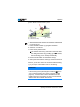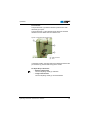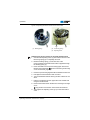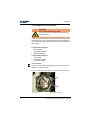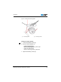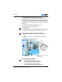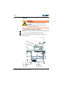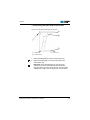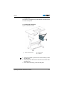
1
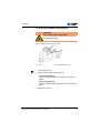
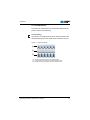
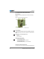
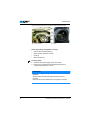
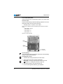
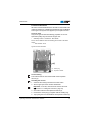
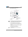
281 Operating Manual All rights reserved. Property of Dürkopp Adler AG and protected by copyright. Any reuse of these contents, including extracts, is prohibited without the written approval in advance of Dürkopp Adler AG. Copyright © Dürkopp Adler AG - 2013 Table of contents 1 About this manual .................................................. 3 1.1 1.2 1.3 1.4 Scope of application of the manual........................... 3 Damage during transport .......................................... 3 Limitation of liability................................................... 3 Symbols used ........................................................... 4 2 Safety instructions ................................................. 5 2.1 2.2 General safety instructions ....................................... 5 Signal words and symbols used in safety instructions................................................................ 7 3 Performance description ....................................... 9 3.1 3.2 3.3 3.4 3.5 Features.................................................................... 9 Declaration of conformity .......................................... 9 Intended use ............................................................. 9 Technical data ........................................................ 10 Additional equipment .............................................. 11 4 Device description................................................ 15 5 Operation............................................................... 17 5.1 5.2 5.3 5.4 5.5 5.6 5.7 5.7.1 5.7.2 5.8 5.9 5.10 5.11 5.12 Switching the power supply on and off ................... 17 Inserting and replacing the needle.......................... 18 Threading in the needle thread............................... 20 Inserting and winding on the hook thread............... 23 Setting the bobbin filling quantity ............................ 25 Replacing the hook thread bobbin .......................... 26 Thread tension........................................................ 27 Adjusting the needle thread tension ....................... 28 Adjusting the hook thread tension .......................... 30 Setting the thread regulator .................................... 32 Adjusting the stitch length....................................... 34 Setting the sewing foot pressure ............................ 35 Lifting the sewing foot ............................................. 36 Locking the sewing foot in place in the upper position ......................................................... 37 Pushbutton on the machine arm............................. 38 Operating the controller .......................................... 39 Control panel for the controller ............................... 39 Sewing .................................................................... 42 5.13 5.14 5.14.1 5.15 Operating manual 281 Version 06.0 - 05/2013 1 Table of contents 2 6 Maintenance .......................................................... 45 6.1 6.2 6.2.1 6.2.2 6.3 Cleaning work ......................................................... 45 Lubrication .............................................................. 47 Hook lubrication ...................................................... 48 Gear lubrication ...................................................... 49 Repairs ................................................................... 50 7 Set-up..................................................................... 51 7.1 7.2 7.3 7.4 7.5 7.6 7.7 7.7.1 7.7.2 7.8 7.9 7.10 7.11 7.12 7.13 7.13.1 7.13.2 7.13.3 7.14 Checking the scope of delivery............................... 51 Removing the transport securing devices............... 52 Fitting the frame components ................................. 53 Completing the table plate ...................................... 54 Fastening the table plate to the frame .................... 55 Setting the working height ...................................... 56 Controller ................................................................ 57 Fitting the controller ................................................ 57 Fit the pedal and setpoint device ............................ 58 Inserting the machine upper section....................... 59 Attaching the upper section retaining strap ............ 60 Attaching the oil can ............................................... 60 Fitting the knee lever .............................................. 61 Attaching the control panel ..................................... 62 Electrical connection............................................... 63 Checking the mains voltage.................................... 63 Connecting the controller........................................ 63 Establishing equipotential bonding ......................... 65 Sewing test ............................................................. 66 8 Disposal................................................................. 67 9 Appendix ............................................................... 68 Operating manual 281 Version 06.0 - 05/2013 About this manual 1 About this manual 1.1 Scope of application of the manual This manual describes the intended use and the set-up of the special sewing machine 281. It applies to all submodels listed in Section 3 Performance description. 1.2 Damage during transport Dürkopp Adler cannot be held liable for any damage during transport. Check the delivered product immediately after receiving it. Report any damage to the last transport manager. This also applies if the packaging is not damaged. Keep the machines, devices, and packaging material in the condition they were at the time the damage was identified. That secures any claims towards the transport company. Report all other complaints to Dürkopp Adler immediately after receiving the product. 1.3 Limitation of liability All information and notes in this operating manual have been compiled in accordance with the latest technology and the applicable standards and regulations. The manufacturer accepts no liability for any damage due to: • • • • • • Failure to observe the instructions in the manual Improper use Unauthorized modifications to the machine The deployment of untrained personnel Damage during transport Using spare parts not approved Operating manual 281 Version 06.0 - 05/2013 3 About this manual 1.4 Symbols used Correct setting Specifies the correct setting. Faults Specifies the faults that can occur due to an incorrect setting. Steps to be performed when operating the machine (sewing and equipping) Steps to be performed for servicing, maintenance, and installation Steps to be performed via the software control panel The individual steps are numbered: 1. 1. First step 2. 2. Second step ... The sequence of the steps must always be followed. Result of performing an operation Change to the machine or in the display. Important Special attention must be paid to this point when performing a step. Information Additional information, e. g. on alternative operating possibilities. Sequence Specifies the work to be performed before or after a setting. It is vital that this sequence is adhered to. Reference A reference is provided to another place in the text. 4 Operating manual 281 Version 06.0 - 05/2013 Safety instructions 2 Safety instructions This section contains basic instructions for your safety. Read the instructions carefully before setting up, programming, maintaining, or operating the machine. Make sure to follow the information included in the safety instructions. Failure to do this can result in serious injury and damage to the machine. 2.1 General safety instructions Only authorized persons may use the machine. Every person who works with the machine must have read the operating manual first. The machine may only be used as described in this manual. The operating manual must be available at the machine's location at all times. Also observe the safety instructions and the operating manual for the drive. Observe the generally applicable safety and accident prevention regulations and the legal regulations concerning industrial safety and the protection of the environment. All warnings on the machine must always be in legible condition and may not be removed. Missing or damaged labels must be replaced immediately. For the following work, the machine must be disconnected from the power supply using the main switch or by disconnecting the power plug: • • • • Threading Replacing the needle or other sewing tools Leaving the workplace Performing maintenance work and repairs Operating manual 281 Version 06.0 - 05/2013 5 Safety instructions Inspect the machine while in use for any externally visible damage. Interrupt your work if you notice any changes to the machine. Report any changes to your supervisor. A damaged machine may not be used any more. Machines or machine parts that have reached the end of their service life must not be used any longer. They have to be disposed of correctly and in accordance with the applicable statutory provisions. The machine may only be set up by qualified specialists. Maintenance work and repairs may only be carried out by qualified specialists. Safety equipment may not be removed or put out of service. If this cannot be avoided for a repair operation, the safety equipment must be refitted and put back into service immediately afterwards. Work on electrical equipment may only be carried out by qualified electrical specialists. The connecting cable must have a power plug approved in the specific country. The power plug may only be connected to the power cable by a qualified electrical specialist. Work on live components and equipment is prohibited. Exceptions are defined in DIN VDE 0105. Missing or faulty spare parts could impair safety and damage the machine. Therefore only use original spare parts from the manufacturer. 6 Operating manual 281 Version 06.0 - 05/2013 Safety instructions 2.2 Signal words and symbols used in safety instructions The safety instruction text is surrounded by colored bars. Signal words specify the severity of a danger: • • • • Danger: Warning: Caution: Attention: Resulting in death or serious injury. Death or serious injury possible. Moderate to minor injuries are possible. Damage possible. In the case of dangers to personnel, the following symbols indicate the type of hazard: General danger Danger due to electric shock Danger due to sharp objects Danger due to crushing Operating manual 281 Version 06.0 - 05/2013 7 Safety instructions Examples of the layout of the safety instructions in the text: DANGER Type and source of the danger Consequences in the event of noncompliance Measures for avoiding the danger This is what a hazard note looks like for a hazard that will result in serious injury or even death if not complied with. CAUTION Type and source of the danger Consequences in the event of noncompliance Measures for avoiding the danger This is what a hazard note looks like for a hazard that could result in moderate or minor injury if not complied with. ATTENTION Type and source of the danger Consequences in the event of noncompliance Measures for avoiding the danger This is what a hazard note looks like for a hazard that could result in material damage if not complied with. ENVIRONMENTAL PROTECTION Type and source of the danger Consequences in the event of noncompliance Measures for avoiding the danger This is what an environmental protection note looks like for a hazard that could result in environmental damage if not complied with. 8 Operating manual 281 Version 06.0 - 05/2013 Performance description 3 Performance description 3.1 Features The Dürkopp Adler 281 is a single-needle double lockstitch machine with lower transport for light to moderately heavy material. General technical characteristics • Comes with standard E2/20 sewing equipment (E2/16 for China) • Integrated sewing drive on the upper shaft • Maximum sewing speed: 4000 or 5000 st/min (depending on submodel) • Maximum stitch length 4.5 or 6 mm (depending on submodel) • Sewing foot pressure adjustable with adjusting wheel • Electromagnetic thread cutter • Electromagnetic thread clamps, can be activated on the control panel • Electromagnetic automatic tying stitch • Integrated operation lock for sewing drive when the upper part is pivoted • Integrated winder 3.2 Declaration of conformity The machine complies with the European regulations specified in the declaration of conformity or in the installation declaration. 3.3 Intended use The Dürkopp Adler 281 is intended for sewing light to moderately heavy material. Intended yarn counts: • 30/3 NeB (cotton threads) • 30/2 Nm (synthetic threads) • 30/3 Nm (core spun thread) The machine is only intended for processing dry material and may only be operated in dry areas. The material to be sewn must not contain any hard objects. The sewing machine is intended for industrial use. The manufacturer will not be held liable for damage resulting from improper use. Operating manual 281 Version 06.0 - 05/2013 9 Performance description 3.4 Technical data Noise emission Workplace-specific emission value as per DIN EN ISO 10821: 281-140342: LC = 78 dB (A) ± 0.96 dB (A) At: Stitch length: 3.2 mm Number of stitches: 4400 min-1 Material to be sewn: 2-layer material G1 DIN 23328 Features 281140342-02 281160362-02 281140342-01 A Sewing stitch type Double lockstitch 301 Hook type Horizontal hook, small Oiling oiled Number of needles 1 Needle system 134 134 DBx1 Needle bar piston dimension [mm] 2.0 2.0 1.62 65 –100 90 – 130 #9 – #16 50/3 30/3 50/3 Max. needle strength [Nm] Max. sewing thread size Max. stitch length, forwards/backwards [mm] 4.5 6 4.5 Max. number of stitches [rpm] 5000 4000 5000 Number of stitches on delivery [rpm] 4800 4000 4800 Max. sewing foot stroke (lifting with knee lever) [mm] 14.5 16 14.5 Max. sewing foot stroke (lifting with magnet) [mm] 12 Sewing foot stroke on delivery 9 Rated voltage [V/Hz] Rated voltage on delivery [V/Hz] Rated power [kVA] 200 – 240 V 50/60 Hz 1x230 V 50/60 Hz 0.5 Length/width/height [mm] 540/430/215 Pack size incl. upper part, accessory pack, and controller (length/width/height) [mm] 785/694/300 Total weight (incl. packaging) [kg] 10 54.5 Operating manual 281 Version 06.0 - 05/2013 Performance description 3.5 Additional equipment Additional equipment Electromagnetic foot lifting (attachment set) Material number 281140342-02 281160362-02 0281 590044 281140342-01 A x Multi-function pushbutton incl. LED 0281 590114 sewing lamp and connecting circuit board incl. sewing lamp transformer for DAC-BASIC (attachment set) x x x LED sewing lamp (Luce, on sewing 0281 590034 machine upper section) x x x Right edge stop, 0-14 mm, fastening on foundation plate, can be horizontally pivoted outwards N900 012015 X x x Right edge stop, 0-50 mm, fastening on foundation plate, can be pivoted upwards, fastening on fabric bar bush N900 020021 x x x Right edge stop, 0-40 mm, with lifting sewing foot, fastening on fabric bar N900 023421 x x x Right edge stop, can be pivoted outwards, fastening on foundation plate N900 011035 x x x Edge stop, r.h. with roller, fastening N800 015412 on foundation plate x x x Swivel arm for apparatus fastening N900 001941 x x x Kit for moving binder for fine material N900 003441 x x Compensating hinged foot for edge 0204 001322 stitching, 0.8 mm to the right of the needle x x = standard equipment X = optional additional equipment Operating manual 281 Version 06.0 - 05/2013 11 Performance description Additional equipment Material number 281140342-02 281160362-02 281140342-01 A Compensating hinged foot for edge 0204 001321 stitching, 0.8 mm to the left of the needle x x Compensating hinged foot for edge stitching, 1.6 mm to the right of the needle 0204 001322A x x Compensating hinged foot for edge stitching, 1.6 mm to the left of the needle 0204 001321A x x Compensating hinged foot for edge 0204 001323 stitching, 0.8 mm to the right and left of the needle, springy x x Compensating hinged foot for edge stitching, 3.2 mm to the right of the needle 0204 001322B x x Compensating hinged foot for edge stitching, 4.8 mm to the right of the needle 0204 001322C x x Zipper foot, on both sides 0272 006853 x x Zipper foot, right sole 0272 006858 x x Zipper foot, left sole 0272 006854 x x Hinged foot with wide sole for 0204 000850 adjustment when using attachment hems x x Apparatus to N514 with air, 8 mm fold-over bridge, 1.2 mm passage (incl. WE8) 0281 590134 x x Pneumatic connection package 0797 003031 x x x = standard equipment X = optional additional equipment 12 Operating manual 281 Version 06.0 - 05/2013 Performance description Material number 281140342-02 281160362-02 281140342-01 A Frame incl. 1060x500 mm table plate with a pedal and drawer MG53 400454 x x x Frame with rollers incl. 1250x900x700 mm table plate with a pedal and drawer MG53 400554 x x x Additional equipment Frames = standard equipment X = optional additional equipment Operating manual 281 Version 06.0 - 05/2013 13 Performance description 14 Operating manual 281 Version 06.0 - 05/2013 Device description 4 Device description Figure 1: Complete overview ② ① ⑪ ③ ④ ⑩ ⑤ ⑥ ⑦ ⑧ ⑨ (1) - Control panel (2) - Preliminary tensioner (3) - Thread regulator (4) - Main tensioner (5) - Needle bar (6) - Pushbutton on the machine arm (7) - Adjusting wheel for the sewing foot pressure (8) - Stitch adjustment lever (9) - Adjusting wheel for the stitch length (10) - Handwheel (11) - Bobbin Operating manual 281 Version 06.0 - 05/2013 15 Device description 16 Operating manual 281 Version 06.0 - 05/2013 Operation 5 Operation 5.1 Switching the power supply on and off The controller is underneath the table plate. The main switch (1) on the controller regulates the power supply. Figure 2: Switching the power supply on and off ① ② (1) - Main power switch (2) - Indicator lamp on the controller To switch on the power: 1. Press the main switch (1) down to position I. The indicator lamp (2) lights up. To switch off the power: 1. Press the main switch (1) up to position 0. The indicator lamp (2) goes out. Operating manual 281 Version 06.0 - 05/2013 17 Operation 5.2 Inserting and replacing the needle WARNING Risk of injury by the needle point and moving parts. Switch off the sewing machine before replacing the needle. Do not touch the needle point. Sequence After changing to a needle of a different size, adjust the clearance between the hook and the needle ( Service manual). ATTENTIO Damage to the machine, needle breakage, or thread damage is possible due to an incorrect clearance between the needle and hook tip. Check the clearance to the hook tip after inserting a new needle of a different size. Adjust this if necessary. Faults caused by an incorrect hook clearance After inserting a thinner needle: • Missing stitches • Thread damage After inserting a thicker needle: • Damage to the hook tip • Damage to the needle 18 Operating manual 281 Version 06.0 - 05/2013 Operation Figure 3: Inserting and replacing the needle ① ④ ② (1) - Needle bar (2) - Fastening screw ③ (3) - Hook (4) - Groove 1. Turn the handwheel until the needle bar (1) reaches the upper end position. 2. Loosen the fastening screw (2). 3. Pull the needle out towards the bottom. 4. Insert the new needle. 5. Important: Align the needle so that the groove (4) faces the hook (3). 6. Tighten the fastening screw (2). Operating manual 281 Version 06.0 - 05/2013 19 Operation 5.3 Threading in the needle thread WARNING Risk of injury by the needle point and moving parts. Switch off the sewing machine before inserting the thread. Figure 4: Thread guide on the unwinding bracket ① ② (1) - Guide on the unwinding bracket (2) - Thread stand 1. Fit the thread reel on the thread stand (2). 2. Insert the thread from the rear to the front through a hole in the guide on the unwinding bracket (1). Important: The unwinding bracket (1) must be parallel to the thread stand (2). 20 Operating manual 281 Version 06.0 - 05/2013 Operation Figure 5: Threading procedure for needle thread - part 1 ⑤ ① ② ③ ④ ⑤ ⑧ ⑥ (1) (2) (3) (4) - ⑦ First thread guide Second thread guide Pre-tensioner Thread regulator (5) (6) (7) (8) - Thread tensioning spring Hook Main tensioner Thread tension magnet 3. Insert the thread from top to bottom through the first thread guide (1). 4. Insert the thread in a wavelike manner through the 3 holes of the 2nd thread guide (2): From the right to the left and through the rear hole, from the left to the right through the center hole, and from the right to the left through the front hole. 5. Guide the thread counterclockwise around the pretensioner (3). 6. Press in the pin (8) on the thread tension magnet on the rear side of the machine to release the main tensioner. 7. Guide the thread clockwise around the main tensioner (7). 8. Pull the thread under the thread tensioning spring (5). 9. Guide the thread through, from the right to the left and under the hook (6). 10. Feed the thread from bottom to top through the thread regulator (4). Operating manual 281 Version 06.0 - 05/2013 21 Operation Figure 6: Threading procedure for needle thread - part 2 ⑨ ⑩ ⑪ ⑫ ⑬ ⑭ (9) (10) (11) (12) - Thread lever Thread lever protection Thread guide Thread clamp (13) - Thread guide on the needle bar (14) - Needle eye 11. Insert the thread from the right to the left through the thread lever (9) behind the thread lever protection (10). 12. Insert the thread through the thread guide (11). 13. Insert the thread through the thread clamp (12). 14. Insert the thread through the thread guide on the needle bar (13). 15. Insert the thread from the left to the right through the needle eye (14). 22 Operating manual 281 Version 06.0 - 05/2013 Operation 5.4 Inserting and winding on the hook thread WARNING Risk of injury from moving parts. Switch off the sewing machine before inserting the thread. 1. Fit the thread reel onto the thread stand ( page 20). 2. Insert the thread from the rear to the front through a hole in the guide on the unwinding bracket. Important: The unwinding bracket must be parallel to the thread stand. Figure 7: Winding on the hook thread - part 1 ① ② ③ (1) - First thread guide (2) - Bobbin shaft (3) - Bobbin winder flap ⑤ ④ (4) - Second thread guide (5) - Adjusting knob 3. Fit the empty bobbin onto the bobbin shaft (2). 4. Insert the thread in a wavelike manner through the three holes on the first thread guide (1): From the rear to the front through the left hole, from the front to the rear through center hole, and finally from the rear to the front through the right hole. 5. Insert the thread from the left to the right through the hole on the second thread guide (4). 6. Guide the thread clockwise around the gap on the adjusting knob (5). 7. Guide the thread from the right to the left through the hole on the second thread guide (4) to the bobbin. Operating manual 281 Version 06.0 - 05/2013 23 Operation Figure 8: Winding on the hook thread - part 2 ② ③ ⑥ (2) - Bobbin shaft (3) - Bobbin winder flap (6) - Cutter 8. Wind the hook thread clockwise onto the bobbin until the thread no longer slips off. 9. Press the bobbin winder flap (3) against the bobbin. 10. Switch on the machine. 11. Press the foot pedal forwards. The machine starts sewing and winds on the hook thread in the process. When the set filling quantity ( Section 5.5 Setting the bobbin filling quantity, page 25) is reached, then the winding process will stop automatically. 12. Remove the full bobbin from the bobbin shaft (2). 13. Clamp the thread under the cutter (6) and tear the thread off. The hook thread is normally wound on when sewing is in progress. However, you can also wind on the hook thread without sewing, e.g. if you require a full bobbin in order to start sewing. ATTENTIO Risk of damaging the machine when winding without material to be sewn. Lock the sewing foot in place using the hand lever ( Section 5.12 Locking the sewing foot in place in the upper position, page 37). Take the thread out of the thread lever and the bobbin capsule out of the hook if you wind on the hook thread without sewing the material in the process. 24 Operating manual 281 Version 06.0 - 05/2013 Operation 5.5 Setting the bobbin filling quantity WARNING Risk of injury from moving parts. Switch off the sewing machine before setting the bobbin filling quantity. Figure 9: Setting the bobbin filling quantity ① ② (1) - Screw (2) - Metallic bobbin winder 1. Loosen the screw (1). 2. Set the metallic bobbin winder piece (2): • Lower filling quantity: Pivot the metallic bobbin winder piece (2) towards the bobbin. • Larger filling quantity: Pivot the metallic bobbin winder piece (2) away from the bobbin. 3. Tighten the screw (1). Operating manual 281 Version 06.0 - 05/2013 25 Operation 5.6 Replacing the hook thread bobbin WARNING Risk of injury from moving parts. Switch off the sewing machine before replacing the hook thread bobbin. Figure 10: Replacing the hook thread bobbin ① ⑤ ② ③ (1) - Spool housing upper section (2) - Spool housing flap ④ (3) - Bobbin (4) - Tensioning spring (5) - Hole 1. Raise the spool housing flap (2). 2. Remove the spool housing upper section (1) together with the bobbin (3). 3. Remove the empty bobbin. 4. Insert a full bobbin. Important: Insert the bobbin (3) such that it moves in the direction of the arrow when pulling off the thread. 5. Guide the hook thread through the slot underneath the tensioning spring (4) and into the hole (5). 6. Pull the hook thread approx. 5 cm out of the spool housing upper section (1). 7. Insert the spool housing upper section (1) with the full bobbin. 8. Close the spool housing flap (2). 26 Operating manual 281 Version 06.0 - 05/2013 Operation 5.7 Thread tension The tension of needle thread and hook thread determines the position of the thread interlacing. Correct setting If the tension of needle thread and hook thread is identical, the thread interlacing lies in the middle of the material to be sewn. Figure 11: Thread interlacing ① ② ③ (1) - Identical needle thread and hook thread tension (2) - Hook thread tension higher than needle thread tension (3) - Needle thread tension higher than hook thread tension Operating manual 281 Version 06.0 - 05/2013 27 Operation 5.7.1 Adjusting the needle thread tension Main tensioner The main tensioner (2) determines the normal tension during sewing. Figure 12: Adjusting the needle thread tension ① ② (1) - Pre-tensioner (2) - Main tensioner Correct setting The main tension should be set as low as possible. The thread interlacing should be exactly in the middle of the material being sewn. Faults due to excessively high tension • Crimping • Thread breakage Adjusting the main tension • To increase the tension: Turn the adjusting wheel (2) clockwise. • To reduce the tension: Turn the adjusting wheel (2) counterclockwise. Opening the needle thread tensioner The main tensioner is automatically opened when the thread is cut. 28 Operating manual 281 Version 06.0 - 05/2013 Operation Pre-tensioner The pre-tensioner (1) holds the thread in position if the main tensioner (2) is open. The pre-tensioner (1) also determines the length of the initial thread for the new seam when the thread is cut: Figure 13: Adjusting the pre-tensioner ① ③ ② (1) - Pre-tensioner (2) - Main tensioner (3) - Bolt In the basic position, the upper side of the adjusting wheel for the pre-tensioner (1) is flush with bolt (3) in the center. To adjust the pre-tensioner: • Shorter initial thread: Turn the adjusting wheel (1) clockwise. • Longer initial thread: Turn the adjusting wheel (1) counterclockwise. Operating manual 281 Version 06.0 - 05/2013 29 Operation 5.7.2 Adjusting the hook thread tension WARNING Risk of injury from moving parts. Switch off the sewing machine before adjusting the hook thread tension. Figure 14: Adjusting the hook thread tension ① ② ③ (1) - Bobbin (2) - Tensioning spring (3) - Braking spring The braking spring (3) and tensioning spring (2) together determine the hook thread tension. The braking spring (3) also prevents the bobbin from running on when the thread is cut. Correct setting • The thread interlacing should be exactly in the middle of the material being sewn ( Section 5.7 Thread tension, page 27). • If the loose thread end is held tightly, then the spool housing should slowly lower through its own weight when the bobbin (1) is full. • The total value of the hook thread tension should be applied 50% respectively through the braking spring (3) and the tensioning spring (2). 30 Operating manual 281 Version 06.0 - 05/2013 Operation Figure 15: Adjusting the tension values for the hook thread ① (1) - Braking spring ② ③ (2) - Tensioning spring (3) - Adjusting screw Adjusting the tension values for the hook thread tension 1. Turn back the adjusting screw (3) such that the tension on the tensioning spring (2) is completely removed. 2. Bend the braking spring (1) such that 50% of the recommended hook thread tension value is applied through the braking spring (1). 3. Insert the bobbin into the spool housing upper section and thread in the hook thread ( Section 5.4 Inserting and winding on the hook thread, page 23). 4. Insert the spool housing together with the bobbin into the hook. 5. Hold tight the free thread end with one hand. 6. Turn the handwheel until the sewing machine carries out one stitch. 7. Pull the hook thread onto the upper side of the needle hole using the needle thread. 8. Remove the hook thread in the direction of sewing at an angle of 45°. Fifty percent of the tension value should be achieved. 9. Then tighten the adjusting screw (3) up to the total tension value. Operating manual 281 Version 06.0 - 05/2013 31 Operation 5.8 Setting the thread regulator WARNING Risk of injury from moving parts. Switch off the sewing machine before setting the thread regulator. The thread regulator determines the needle thread quantity to be guided around the hook. The required thread quantity depends on the thickness of the material to be sewn, thread strength, and stitch length. Larger thread quantity for • thick material • high thread strengths • large stitch lengths Lower thread quantity for • thin material • low thread strengths • small stitch lengths Correct setting: The loop of the needle thread (2) slides at low tension over the thickest point of the hook (1). Figure 16: Setting the thread regulator: Correct needle thread quantity ① ② (1) - Hook 32 (2) - Needle thread loop Operating manual 281 Version 06.0 - 05/2013 Operation Figure 17: Setting the thread regulator ② ① (1) - Thread regulator (2) - Fastening screws Setting the thread regulator 1. Loosen the fastening screws (2). 2. Move the thread regulator (1): • Lower thread quantity: Slide the thread regulator (1) to the right • Larger thread quantity: Slide the thread regulator (1) to the left 3. Tighten the fastening screws (2). Operating manual 281 Version 06.0 - 05/2013 33 Operation 5.9 Adjusting the stitch length The stitch length can be adjusted continuously by turning the adjusting wheel (2). The adjusting mark (3) above the wheel indicates the stitch length selected. Use the stitch adjustment lever (1) to switch over to backwards sewing. The stitch length is the same size for forwards and backwards sewing. Figure 18: Adjusting the stitch length ③ ① ② (1) - Stitch adjustment lever (2) - Adjusting wheel for the stitch length Adjusting the stitch length 1. Turn the adjusting wheel (2) • Larger stitch length: Turn the adjusting wheel (2) counterclockwise. • Smaller stitch length: Turn the adjusting wheel (2) clockwise. Sewing backwards/manual bartack 1. Slowly push the stitch adjustment lever (1) down as far as it will go. The stitch length is reduced. Backwards sewing starts after the zero point. In the lower end position, the machine sews backwards with the set stitch length. 34 Operating manual 281 Version 06.0 - 05/2013 Operation 5.10 Setting the sewing foot pressure The adjusting wheel (2) on the machine arm determines the contact pressure of the sewing foot on the material to be sewn. The pressure can be adjusted continuously by turning the wheel. The adjusting mark (1) above the wheel indicates the pressure selected. • Range for force setting: 10-80 N (10 N=1 kp) • Factory setting: 40 N (at 4800 st/min.) Correct setting The material being sewn does not slip and is correctly transported. The correct pressure depends on the material to be sewn. Faults due to incorrectly set sewing foot pressure • Excessively high pressure: Tearing of the material being sewn • Excessively low pressure: Slipping of the material being sewn Figure 19: Setting the sewing foot pressure ① ② (1) - Adjusting mark (2) - Adjusting wheel for the sewing foot pressure Setting the sewing foot pressure: 1. Turn the adjusting wheel (2). • To increase the sewing foot pressure: Turn the adjusting wheel (2) clockwise. • To reduce the sewing foot pressure: Turn the adjusting wheel (2) counterclockwise. Operating manual 281 Version 06.0 - 05/2013 35 Operation 5.11 Lifting the sewing foot The sewing foot can be lifted mechanically or using the knee lever (1) to insert or move the material being sewn. Figure 20: Lifting the sewing foot using the knee lever ① (1) - Knee lever Lifting the sewing foot 1. Push the knee lever (1) to the right. The sewing foot is lifted and stays up for as long as the knee lever is pressed. CAUTION Risk of crushing when lowering the sewing foot. Do not put your hands underneath the lifted sewing foot. Lowering the sewing foot 1. Release the knee lever (1). The sewing foot is lowered. 36 Operating manual 281 Version 06.0 - 05/2013 Operation 5.12 Locking the sewing foot in place in the upper position The lever on the rear side of the machine can be used to hold the lifted sewing foot in the upper position, e. g. in order to wind on the hook thread. Figure 21: Locking the sewing foot in place in the upper position ① (1) - Lever down: Sewing foot down ② (2) - Lever up: Sewing foot locked in place in the upper position Locking the sewing foot in place in the upper position 1. Pivot the lever upwards to position (2). The sewing foot is locked in place in the upper position. CAUTION Risk of crushing when lowering the sewing foot. Do not put your hands underneath the sewing foot if the locking mechanism is removed. Removing the locking mechanism 1. Pivot the lever downwards to position (1). The sewing foot is lowered. The locking mechanism is removed. or 1. Lift the sewing foot using the knee lever ( page 36). The sewing foot is lowered. The locking mechanism is removed. The lever swings back to position (1). Operating manual 281 Version 06.0 - 05/2013 37 Operation 5.13 Pushbutton on the machine arm The machine is equipped with a pushbutton (1) on the machine arm by default. Figure 22: Pushbutton on the machine arm ① (1) - Pushbutton on the machine arm It can be used to switch on various functions depending on the setting on the control panel ( Section 5.14 Operating the controller, page 39): • Bartack sewing • Raising the needle • Bartack suppression A multi-function pushbutton is available as additional equipment: Figure 23: Additional equipment: multi-function pushbutton ② ③ ④ ⑤ Keys for: (2) - Sewing lamp (3) - Bartack suppression (4) - Half stitch/needle position (5) - Manual bartack The buttons can be used to perform the following functions: • • • • 38 Button (2): Switching the sewing lamp on/off Button (3): Activate / deactivate the bartack suppression Button (4): Half stitch, positioning the needle up/down Button (5): Manual bartack Operating manual 281 Version 06.0 - 05/2013 Operation 5.14 Operating the controller The machine is operated using the DAC BASIC controller. Operating the controller is described in an individual operating manual. The operating manual for the DAC BASIC is provided in the accessory pack delivered with the controller. You can also find the operating manual in the download area at www.duerkoppadler.com 5.14.1 Control panel for the controller The DAC BASIC controller is equipped with the OP 1000 control panel. Figure 24: Control panel for the controller ① ② ③ ④ ⑤ ⑯⑮ ⑭ ⑥ ⑦ ⑧⑨ ⑩ ⑬ ⑫ ⑪ Switch on/off function 1. Press the appropriate key. The LED on the key indicates the status. Important: The functions only work on the machine if the appropriate equipment is available. Operating manual 281 Version 06.0 - 05/2013 39 Operation Overview of the functions on the control panel Key Function Status LED display 1 Thread cutter Off LED off On LED on 2 Thread clamp Off LED off On LED on 3 Initial bartack Off LEDs off Single bartack LED bottom right on Double bartack Both LEDs on Off LED off On LED on 4 5 6 7 Multiple initial bartack Softstart Final bartack Multiple final bartack Off LED off On LED on Off LEDs off Single bartack LED top left on Double bartack Both LEDs on Off LED off On LED on 8 Reduced sewing speed Input via +/- keys Off LED off On LED on 9 2. Stitch length Off LED off On LED on 10 Light barrier Off LED off On LED on 11 Seam program III Off LED off On LED on 12 Seam program II Off LED off On LED on 13 Seam program I Off LED off On LED on 14 Sewing foot lifting after sewing stop Sewing foot down LED off 40 Sewing foot up LED on Operating manual 281 Version 06.0 - 05/2013 Operation Key Function 15 Sewing foot position after thread Sewing foot down LED off is cut Sewing foot up LED on 16 Needle position after sewing stop F Freely programmable key ESC Escape key, abort P Programming key + Increase value - Decrease value OK Confirmation Reset Bobbin supply Operating manual 281 Version 06.0 - 05/2013 Status LED display Needle down LED off Needle up LED on Ready to be programmed LED on 41 Operation 5.15 Sewing WARNING Risk of injury from the needle tip when sewing is started unintentionally. Take care not to accidentally press the foot pedal when your fingers are in the needle tip area. The foot pedal starts and controls the sewing process. Figure 25: Sewing with the foot pedal (1) - Pedal position +1: sewing active (2) - Pedal position 0: rest position ① ② ③ ④ (3) - Pedal position -1: moves the sewing foot up (4) - Pedal position -2: sewing the final bartack and cutting off the thread Initial position: To position the material to be sewn: 1. Switch on the sewing machine. 2. Pedal position 0: Machine stationary, needles up, sewing foot down. To position the material to be sewn: 1. Press the foot pedal halfway back in pedal position -1: The sewing foot is raised. 2. Push the material to be sewn into the initial position. Sewing: 1. Press the foot pedal forwards in pedal position +1: The machine sews. The sewing speed increases the further forward the pedal is pressed. 42 Operating manual 281 Version 06.0 - 05/2013 Operation To interrupt sewing: 1. Release the foot pedal in pedal position 0: The machine stops, needles and sewing foot are down. To continue sewing: 1. Press the foot pedal forwards in pedal position +1: The machine continues to sew. To change the stitch length: 1. Turn the adjusting wheel for the stitch length ( Section 5.9 Adjusting the stitch length, page 34). To sew intermediate bartacks: 1. Push the stitch adjustment lever down. ( Section 5.9 Adjusting the stitch length, page 34). or 1. Press the pushbutton on the machine arm (if programmed for that) ( Section 5.13 Pushbutton on the machine arm, page 38) To finish a seam: 1. Press the foot pedal back completely in pedal position -2: The machine sews the final bartack. The thread is cut (if programmed for that). The machine stops. The needle is up. The sewing foot is down. 2. Press the knee lever ( Section 5.11 Lifting the sewing foot, page 36). The sewing foot is lifted. 3. Remove the sewn material. Operating manual 281 Version 06.0 - 05/2013 43 Operation 44 Operating manual 281 Version 06.0 - 05/2013 Maintenance 6 Maintenance This section describes simple maintenance work that needs to be carried out on a regular basis. This maintenance work can be carried out by the operating personnel. Advanced maintenance work may only be carried out by qualified specialists. Advanced maintenance work is described in the service manual. ATTENTION Malfunctions possible due to machine contamination. Sewing dust and thread remains can impair the operation of the machine. Clean the machine at regular intervals as described in the manual. 6.1 Cleaning work Sewing dust and thread remains must be removed at least every 8 operating hours using a compressed-air pistol or a brush. In the case of very fluffy material to be sewn, the machine must be cleaned more frequently. WARNING Risk of injury due to flying particles. Switch off the machine at the main power switch before starting any cleaning work. Flying dirt particles can get in the eyes, causing injury. Hold the compressed-air pistol in such a way that no particles fly near persons. Take care that no particles fly into the oil pan. Operating manual 281 Version 06.0 - 05/2013 45 Maintenance Figure 26: Points that need to be cleaned particularly thoroughly ① ② ③ ④ (1) - Area under the needle plate (2) - Motor fan filter (3) - Spool housing (4) - Hook Areas particularly susceptible to soiling: • Area under the needle plate (1) • Spool housing and inner area (3) • Hook (4) • Motor fan filter (2) Cleaning steps: 1. Switch off the power supply at the main switch. 2. Remove any sewing dust and thread remains using a compressed-air pistol or a brush. ATTENTION Possible damage to the paintwork from solvent-based cleaners. Solvent-based cleaners damage the paintwork of the machine. Only use solvent-free substances for wiping the machine. 46 Operating manual 281 Version 06.0 - 05/2013 Maintenance 6.2 Lubrication WARNING Skin injuries due to contact with oil. Oil can cause a rash if it comes into contact with the skin. Avoid any skin contact with the oil. If oil gets on your skin, wash the affected skin areas thoroughly. ENVIRONMENTAL PROTECTION Risk of environmental damage from oil. Oil is a pollutant and must not enter the sewage system or the soil. Collect waste oil carefully and dispose of it and oily machine parts in accordance with the applicable statutory regulations. ATTENTION Machine damage possible due to incorrect oil level. Too little or too much oil can cause damage to the machine. Make sure that there is always sufficient oil in the respective reservoir. ATTENTION Machine damage possible due to incorrect oil. An incorrect oil type can cause damage to the machine. Only use oil that complies with the data in the operating manual. Operating manual 281 Version 06.0 - 05/2013 47 Maintenance 6.2.1 Hook lubrication Check the oil level for hook lubrication approx. once every week. Oil to be used: Only DA 10 lubricating oil with the following properties or an oil of equivalent quality may be used for the hook: • Viscosity at 40° C: 10 mm²/s - ISO VG10 DA 10 can be obtained under the following part numbers at DA sales offices: • 9047 000011 - 250 ml • 9047 000012 - 1 l • 9047 000013 - 2 l • 9047 000014 - 5 l Figure 27: Hook lubrication ① ② (1) - Refill hole (2) - Oil reservoir Correct setting The oil level must always be between the minimum level marking and the maximum level marking. Checking the oil level 1. Switch off the sewing machine at the main switch. 2. Tilt the upper part of the machine backwards. Important: To do this, the knee lever must be removed. ( Section 7.11 Fitting the knee lever, page 61) 3. Check the quantity of oil in the reservoir (2). 4. Pour in oil through the refill hole (1) as required. 48 Operating manual 281 Version 06.0 - 05/2013 Maintenance 6.2.2 Gear lubrication When the machine is delivered, the oil level is in the middle of the inspection window (2). This filling is intended as a service life filling so that gear oil only has to be topped up in exceptional cases. Oil to be used: Only DA 32 gear oil with the following properties or an oil of equivalent quality may be used for the gear unit: • Viscosity at 40° C: 32 mm²/s - ISO VG32 DA 32 can be obtained under the following part number at DA sales offices: • 9047 000032 - 90 ml Figure 28: Gear lubrication ① ② (1) - Screw plug (2) - Inspection window Correct setting The oil level must be around the middle of the inspection window (2). Checking the oil level 1. Switch off the sewing machine at the main switch. 2. Tilt the upper part of the machine backwards. Important: To do this, the knee lever must be removed. ( Section 7.11 Fitting the knee lever, page 61) 3. Check the oil level in the inspection window (2). 4. Unscrew the screw plug (1) together with the sealing ring. 5. Top up the gear oil to the middle of the inspection window (2). Operating manual 281 Version 06.0 - 05/2013 49 Maintenance 6.3 Repairs Contacts for repair in the event of damage to the machine: Dürkopp Adler AG Potsdamer Str. 190 33719 Bielefeld Ph. +49 (0) 180 5 383 756 Fax +49 (0) 521 925 2594 Email: [email protected] Internet: www.duerkopp-adler.com 50 Operating manual 281 Version 06.0 - 05/2013 Set-up 7 Set-up WARNING Risk of injury. The machine may only be set up by trained specialists. Wear safety gloves and safety shoes when unpacking and setting up. 7.1 Checking the scope of delivery Important: The scope of delivery depends on your specific order. 1. Prior to set-up, check that all parts are present. Figure 29: Example of scope of delivery when all components are delivered complete ① ⑩ ② ③ ④ ⑨ ⑤ ⑧ ⑦ ⑥ (1) (2) (3) (4) (5) - Control panel Upper part of machine Table plate Drawer Frame Operating manual 281 Version 06.0 - 05/2013 (6) (7) (8) (9) (10) - Pedal Rod Oil pan Controller Thread stand 51 Set-up Standard equipment: • Upper part of machine (2) • Oil pan (8) -in the accessory kit • Thread stand with unwinding bracket (10) – in the accessory kit • Controller (9) • Control panel for the controller (1) • Knee lever (not illustrated) • Rod (7) Optional additional equipment: • Table plate (3) • Drawer (4) • Frame (5) • Pedal (6) • Sewing light (not illustrated) 7.2 Removing the transport securing devices All transport securing devices must be removed prior to set-up. 1. Remove the lashing straps and wooden blocks from the machine upper section, the table, and the frame. 2. Remove the supporting wedges between the machine arm and needle plate. 52 Operating manual 281 Version 06.0 - 05/2013 Set-up 7.3 Fitting the frame components Figure 30: Fitting the frame components ① ② ③ ④ ⑤ (1) - Head sections (2) - Frame bars (3) - Cross bars (4) - Foot struts (5) - Cross strut 1. Screw the cross bars (3) onto the frame bars (2). 2. Screw the cross strut (5) onto the foot struts (4). 3. Screw the head sections (1) onto the frame bars (2). Operating manual 281 Version 06.0 - 05/2013 53 Set-up 7.4 Completing the table plate The table plate belongs to the optional delivery scope. Drawings are provided in Appendix to allow you to independently assemble a table plate. Figure 31: Completing the table plate ① ② ③ ⑥ ④ (1) - Thread stand (2) - Support (3) - Lower hinge parts ⑤ (4) - Drawer (5) - Oil pan (6) - Rubber corners 1. Screw the drawer (4) in place with two brackets and six screws (3.5 x 17) to the left, under the table plate. 2. Screw the oil pan (5) in place with eight screws (3.9 x 15) under the recess for the machine. 3. Insert the support (2) into the hole. 4. Fit the lower hinge parts (3) into the recesses. 5. Fit the rubber corners (6) into the corner protrusions. 6. Insert the thread stand (1) into the hole. 7. Fasten the thread stand (1) with nut and washer. 8. Screw the thread reel holder and the unwinding bracket onto the thread stand (1) in such a way that they are exactly parallel above each other. 54 Operating manual 281 Version 06.0 - 05/2013 Set-up 7.5 Fastening the table plate to the frame Figure 32: Fastening the table plate to the frame ① ② ③ (1) - Table plate (2) - Head sections (3) - Foot struts 1. Place the table plate (1) onto the head sections (2). 2. Tighten the table plate (1) on both sides using wood screws (B8 x 35). Important: Screw the table plate (1) onto the head sections (2) such that the table plate is flush with the rear edge of the foot struts (3) at the rear. This increases stability when folding over the upper part of the machine. Operating manual 281 Version 06.0 - 05/2013 55 Set-up 7.6 Setting the working height The working height is continuously adjustable between 750 and 900 mm (clearance between the floor and upper edge of the table plate). Figure 33: Setting the working height ① ① (1) - Screws 1. Loosen all four screws (1) on the head sections. 2. Set the table plate to the desired height. Important: Pull out or push in the table plate evenly at both sides to prevent it from jamming. 3. Tighten the screws (1) on the head sections. 56 Operating manual 281 Version 06.0 - 05/2013 Set-up 7.7 Controller The machine is operated using the DAC BASIC controller with the OP 1000 control panel. 7.7.1 Fitting the controller Figure 34: Fitting the controller ② ① ③ (1) - Strain relief mechanism (2) - Screw holder (3) - Controller 1. Screw the controller (3) onto the four screw holders (2) under the table plate. 2. Clamp the power cable for the controller into the strain relief mechanism (1). 3. Screw the strain relief (1) under the table plate. Operating manual 281 Version 06.0 - 05/2013 57 Set-up 7.7.2 Fit the pedal and setpoint device Figure 35: Fitting the setpoint device ① ② ③ ⑥ ④ ⑤ (1) - Angle piece (2) - Setpoint device (3) - Screw (4) - Pedal rod (5) - Pedal (6) - Cross strut 1. Fit the pedal (5) onto the cross strut (6) and align it in such a way that the middle of the pedal is under the needle. The cross strut has elongated holes to allow alignment of the pedal. 2. Screw the pedal (5) firmly onto the cross strut (6). 3. Screw the setpoint device (2) onto the angle piece (1). 4. Screw the angle piece (1) under the table plate so that the pedal rod (4) runs vertically to the pedal (5) from the setpoint device (2). 5. Hang the pedal rod (4) with the ball socket on the setpoint device (2) and attach to the pedal (5). 6. Pull the pedal rod (4) to the correct length: Correct setting: 10° inclination with pedal (5) released 7. Tighten the screw (3). 58 Operating manual 281 Version 06.0 - 05/2013 Set-up 7.8 Inserting the machine upper section Figure 36: Inserting the machine upper section ① ② (1) - Upper hinge parts (2) - Rubber inlays WARNING Risk of crushing. The machine upper section is heavy. Take care not to jam your hands when fitting the machine upper section. This especially applies when fitting the upper hinge parts into the rubber inlays. 1. Screw the upper hinge parts (1) onto the machine upper section. 2. Fit the machine upper section from above at an angle of 45°. 3. Insert the upper hinge parts (1) into the rubber inlays (2). 4. Fold the machine upper section down and insert it in the recess. Operating manual 281 Version 06.0 - 05/2013 59 Set-up 7.9 Attaching the upper section retaining strap The machine upper section is secured with a retaining strap so that it does not slip out of the brackets when being folded over backwards. Figure 37: Attaching the upper section retaining strap ① ② (1) - Retaining strap ③ (2) - Flap (3) - Oil pan 1. Tilt the machine upper section backwards. 2. Pull the retaining strap (1) from the machine upper section through the cut-out and under the table plate. 3. Screw the retaining strap (1) firmly to the flap (2) for the oil pan (3) using a screw. 7.10 Attaching the oil can Figure 38: Attaching the oil can ① (1) - Oil pan ② (2) - Oil can 1. Tilt the machine upper section backwards. 2. Attach the oil can (2) into the oil pan (1) from below. 60 Operating manual 281 Version 06.0 - 05/2013 Set-up 7.11 Fitting the knee lever Use the knee lever to mechanically lift the sewing foot. Figure 39: Fitting the knee lever ① ② ⑥ ⑤ ③ ④ (1) - Knee lever joint (2) - Knee lever shaft (3) - Screw (4) - Knee pad (5) - Shaft (6) - Hole 1. Guide the knee lever shaft (2) through the hole (6) in the oil pan. 2. Attach the knee lever shaft (2) to the shaft (5). 3. Loosen the screws on the knee lever joint (1). 4. Set the rod for the knee lever such that it can easily be operated using the right knee. 5. Tighten the screws on the knee lever joint (1). 6. Loosen the screw (3). 7. Align the knee pad (4) such that the knee lever can easily be operated using the right knee. 8. Tighten the screw (3). Removing the knee lever prior to folding over the upper section If, in a fully installed machine, the upper section is going to be tilted backwards, e.g. for maintenance work, then the knee lever has to be removed previously in order to do this. Operating manual 281 Version 06.0 - 05/2013 61 Set-up 7.12 Attaching the control panel Figure 40: Attaching the control panel ② ③ ⑤ ① ⑥ ④ ⑦ ⑥ (1) (2) (3) (4) - Cable holder Control panel Control panel bracket Fastening screws (5) - Handwheel screws (6) - Handwheel cover screws (7) - Handwheel cover 1. Loosen the fastening screws (4). 2. Remove the control panel bracket (3). 3. Screw the control panel (2) onto the control panel bracket (3). 4. Screw the control panel bracket (3) firmly onto the machine arm again using the fastening screws (4). 5. Screw the connecting cable for the control panel firmly onto the machine arm using the cable holder (1). 6. Loosen all three handwheel screws (5). 7. Loosen all four handwheel cover screws (6). 8. Remove the handwheel cover (7). 9. Install the connecting cable for the control panel tidily underneath the handwheel cover and guide it downwards through the table plate cut-out. 10. Fit the handwheel cover (7). 11. Tighten all three handwheel screws (5). 12. Tighten all four handwheel cover screws (6). 62 Operating manual 281 Version 06.0 - 05/2013 Set-up 7.13 Electrical connection DANGER Danger to life due to electric shock. The machine may only be connected by trained electrical specialists. Disconnect the power plug before carrying out work on the electrical equipment. Make sure the power plug cannot be unintentionally reinserted. The voltage on the type plate of the sewing drive must correspond to the mains voltage. 7.13.1 Checking the mains voltage Important: The voltage on the type plate of the sewing drive must correspond to the mains voltage. 1. Check the mains voltage before connecting the machine. 7.13.2 Connecting the controller DANGER Danger to life due to electric shock. Disconnect the power plug before connecting the controller. Make sure the power plug cannot be unintentionally reinserted. Connecting the controller consists of the following work: • Insert the plugs of all connecting cables in the sockets on the back of the controller. • Connect the controller to the power supply using the power cable. To do this, read the Operating manual for the DAC BASIC control system. The operating manual is provided in the controller accessory pack. The operating manual for the controller is also available in the download area at www.duerkopp-adler.com. Operating manual 281 Version 06.0 - 05/2013 63 Set-up Figure 41: Connection diagram for DAC basic Front side Rear side ① Plugs ⑦ ⑧ ⑫ ⑬ ⑨ ⑭ ⑩ ⑮ ⑪ ⑯ ⑰ ② ③ ④ ⑤ ⑥ (1) (2) (3) (4) (5) (6) (7) (8) (9) - Switch for sewing lamp Switch for power supply External synchronization Status LEDs Connection for machine upper section Connection for backup dongle Connection for sewing motor Connection for sewing motor encoder Connection for control panel (10) (11) (12) (13) (14) (15) (16) (17) - Connection for foot pedal Machine identification Plug for sewing motor Plug for sewing motor encoder Plug for control panel Plug for footpedal Plug for machine upper section Plug for machine identification Connecting the components to the controller 1. Insert the plugs for the individual components into the respective connecting sockets on the rear side of the controller. 64 Operating manual 281 Version 06.0 - 05/2013 Set-up 7.13.3 Establishing equipotential bonding DANGER Danger to life due to electric shock. Disconnect the power plug before establishing equipotential bonding. Make sure the power plug cannot be unintentionally reinserted. The grounding wire conducts any static charging to ground. Figure 42: Establishing equipotential bonding ① ② ① ③ ① (1) - Grounding wire for machine upper section (2) - Screw (3) - Grounding wire for frame 1. Tilt the machine upper section backwards. 2. Guide the grounding wire (1) for the machine upper section through the table plate cut-out for the controller. 3. Fasten grounding wire (1) for the machine upper section, together with the grounding wire (3) for the frame, to the screw (2) on the rear side of the controller. 4. Raise the machine upper section. Operating manual 281 Version 06.0 - 05/2013 65 Set-up 7.14 Sewing test Carry out a sewing test before starting up the machine. Adjust the machine to the requirements of the material to be sewn. To do this, read the corresponding sections in the Operating manual. Read the corresponding sections in the Service manual in order to make adjustments to the machine if the sewing results do not conform to the requirements. WARNING Risk of injury by the needle point and moving parts. Switch off the sewing machine before replacing the needle, insert the thread, insert the hook thread reel, adjust the hook thread tension and the thread regulator. Performing a sewing test 1. Insert the needle. 2. Wind on the hook thread. 3. Insert the hook thread reel. 4. Thread in the hook thread. 5. Thread in the needle thread. 6. Adjust the thread tension to the material to be sewn. 7. Adjust the thread regulator to the material to be sewn. 8. Adjust the sewing foot pressure to the material to be sewn. 9. Adjust the stitch length. 10. Start the sewing test at low speed. 11. Increase the sewing speed continuously until the working speed is reached. 66 Operating manual 281 Version 06.0 - 05/2013 Disposal 8 Disposal The customer is responsible for disposal of the machine and packaging materials. The machine must not be disposed of via the normal household waste. The machine must be disposed of in an appropriate and correct manner according to the national regulations. ENVIRONMENTAL PROTECTION Risk of environmental damage due to incorrect oil disposal. Incorrect disposal of old oil can result in severe environmental damage. Always follow the statutory rules in regard of disposal. When disposing of the machine, be aware that it consists of a range of different materials (e. g. steel, plastic, electronic components, oily parts). Observe the respectively applicable national regulations for each type of material. Operating manual 281 Version 06.0 - 05/2013 67 Disposal 68 Operating manual 281 Version 06.0 - 05/2013 Appendix 9 Appendix Dimensions for manufacturing a table plate 68 Operating manual 281 Version 06.0 - 05/2013 Appendix 69 Operating manual 281 Version 06.0 - 05/2013 Subject to design changes - Printed in Germany - © Dürkopp Adler AG - Original Instructions - 0791 281750 EN - 06.0 - 05/2013 DÜRKOPP ADLER AG Potsdamer Str. 190 33719 Bielefeld Germany Phone +49 (0) 521 925 00 E-Mail: [email protected] www.duerkopp-adler.com