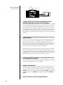
1
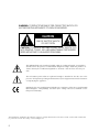
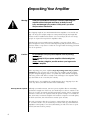
Operating Manual
Mark Levinson®
Nº 333
Nº 332
Nº 331
Dual Monaural
Power Amplifiers
Madrigal Audio Laboratories, Inc.
WARNING: TO REDUCE THE RISK OF FIRE OR ELECTRIC SHOCK, DO
NOT EXPOSE THIS APPLIANCE TO RAIN OR MOISTURE.
CAUTION
RISK OF ELECTRIC SHOCK
DO NOT OPEN
CAUTION: TO REDUCE THE RISK OF ELECTRICAL SHOCK, DO
NOT REMOVE COVER. NO USER-SERVICEABLE PARTS INSIDE.
REFER SERVICING TO QUALIFIED PERSONNEL.
The lightning flash with arrowhead symbol, within an equilateral triangle, is intended to
alert the user to the presence of uninsulated “dangerous voltage” within the product’s enclosure that may be of sufficient magnitude to constitute a risk of electric shock to persons.
The exclamation point within an equilateral triangle is intended to alert the user to the
presence of important operating and maintenance (servicing) instructions in the literature
accompanying the appliance.
Marking by the “CE” symbol (shown left) indicates compliance of this device with the EMC
(Electromagnetic Compatibility) and LVD (Low Voltage Directive) standards of the
European Community.
The information contained in the manual is subject to change without notice. The most current version of this manual will
be posted on our web site at http://www.madrigal.com.
2
Important Safety Instructions
Please read all instructions and precautions carefully and completely before operating your Mark Levinson® power
amplifier.
1.
ALWAYS disconnect your entire system from the AC mains before connecting or disconnecting
any cables, or when cleaning any component.
2.
This product must be terminated with a three-conductor AC mains power cord which includes an
earth ground connection. To prevent shock hazard, all three connections must ALWAYS be used.
3.
AC extension cords are not recommended for use with this product.
4.
NEVER use flammable or combustible chemicals for cleaning audio components.
5.
NEVER operate this product with any covers removed.
6.
NEVER wet the inside of this product with any liquid.
7.
NEVER pour or spill liquids directly onto this unit.
8.
NEVER block air flow through ventilation slots or heatsinks.
9.
NEVER bypass any fuse.
10. NEVER replace any fuse with a value or type other than those specified.
11. NEVER attempt to repair this product. If a problem occurs, contact your Mark Levinson® retailer.
12. NEVER expose this product to extremely high or low temperatures.
13. NEVER operate this product in an explosive atmosphere.
14. ALWAYS keep electrical equipment out of the reach of children.
15. ALWAYS unplug sensitive electronic equipment during lightning storms.
3
From all of us at Madrigal Audio Laboratories, thank you for choosing your Mark
Levinson 300-series Dual Monaural Power Amplifier.
A great deal of effort went into the design and construction of this precision
device. Used properly, it will give you many years of enjoyment.
4
Table of Contents
Unpacking Your Amplifier ........................................................................... 6
Warm up/break-in period ................................................................................. 6
Placement Considerations ......................................................................... 7
Ventilation ........................................................................................................... 7
Operating Voltage, Nº333 ........................................................................... 8
Nº 333 AC mains maximum current requirements .................................... 8
Nº 333 rear-panel label ............................................................................... 9
Operating Voltage, Nº332 & Nº331 ............................................................10
Nº 332 AC mains maximum current requirements .................................. 10
Nº 331 AC mains maximum current requirements .................................... 11
Nº 332/331 rear-panel label ....................................................................... 11
Special Design Features ............................................................................ 12
Massive Power Supply ....................................................................................... 12
Balanced design ............................................................................................... 12
True Voltage Source ........................................................................................... 12
Adaptive Biasing of the Output Stage ........................................................... 13
Extensive Protection .......................................................................................... 13
Front Panel .................................................................................................. 15
Rear Panel .................................................................................................. 16
Remote turn-on tip polarity ...................................................................... 18
Bridged Operation .................................................................................... 22
Bridging Explained ........................................................................................... 22
Balanced Bridging ........................................................................................... 22
Balanced Bridging Kit ............................................................................... 22
Balanced Bridged Input Connection ..................................................... 23
Single-Ended Bridging ...................................................................................... 24
Single-Ended Bridging Kit ......................................................................... 25
Single-Ended Bridged Input Connection ................................................ 25
Biamplification .......................................................................................... 27
Balanced Y-adapter ................................................................................. 27
Passive biamping wiring diagram ........................................................... 28
Care & Maintenance ................................................................................ 29
U.S. and Canadian Warranty .................................................................... 30
Obtaining Service ...................................................................................... 31
Specifications ............................................................................................ 32
Dimensions: Nº 333 & Nº332 ..................................................................... 33
Dimensions: Nº 331 .................................................................................... 35
5
Unpacking Your Amplifier
Warning!
Under no circumstances should you consider unpacking your
amplifier without adequate assistance, as both personal
injury and damage to the product is likely unless you follow
the procedures listed below.
The shipping weight of your Dual Monaural Power Amplifier is over 100 lbs. (45
kg)—the Nº333, for example, weighs in at 150 pounds (68 kg)! Any freight this
massive must be handled with extreme care to avoid injury. At least two strong
people are required to unpack these amplifiers safely.
Included with your new Mark Levinson amplifier is two pairs of knit, white
gloves designed to assist you in the initial unpacking and placement of your new
purchase. Please accept them as a token of our appreciation for having purchased
one of our products.
Caution!
Do not attempt to lift your power amplifier from its packing
carton alone.
Never attempt to lift your power amplifier while bending from
the waist.
Always stand as straight as possible and use your leg muscles
to lift your amplifier.
After unpacking your power amplifier, keep all packing materials for future
transport. In the event that you need to ship your amplifier, only the original,
purpose-designed shipping carton is acceptable. Any other method of shipping
this heavy product will almost certainly result in damage to the amplifier—damage that would not be covered by the warranty.
Carefully inspect your amplifier for possible damage due to shipping. If you discover any, contact your Mark Levinson dealer immediately.
Warm up/break-in period
Although your Mark Levinson 300-series power amplifier delivers outstanding
performance straight out of the box, you should expect to hear it continue to improve as it reaches its normal operating temperatures and its various components
“break-in.” It has been our experience that the greatest changes occur within the
first 25-50 hours, but that the amplifier will continue to improve in sound quality
for about 300 hours, after which time it remains quite constant.
The only exception to this rule is if power is removed from the unit, allowing it
to cool down. In this case you should expect a brief warm-up period before the
amplifier’s sound quality is at its best. (Fortunately, you will never have to repeat
the full 300 hour break-in period.)
6
Placement Considerations
PRECAUTION
For your protection, review “Important Safety Instructions” and
“Operating Voltage” before you install your amplifier.
Your Mark Levinson 300-series power amplifier is specifically designed to stand
on the floor, and must be used as a freestanding unit. In most installations, locating it near the loudspeakers is best. Obviously, this approach minimizes the
length of the speaker wires and necessitates longer interconnecting cables from
the preamplifier to the power amplifier. The advantage to this strategy lies in the
fact that the interconnecting cables carry low-current signals which are more
readily transmitted over distances with great accuracy than are the necessarily
high current signals required by loudspeakers.
Note that adequate clearance for the AC cord and connecting signal cables must
be left behind your amplifier. We suggest leaving at least six inches (15 cm) of
free space behind your amplifier so all cables have sufficient room to bend without crimping or undue strain.
If yours is a CE-certified unit (e.g., European market), the amplifier should also be
placed in such a way that the power switch on the rear panel is easily accessible.
This switch disconnects power from even the supervisory power supply, resulting
in effective disconnection of the amplifier from the AC mains. (Note that under
these conditions, the amplifier cannot respond to remote-turn-on commands, etc.)
Ventilation
As a freestanding unit, your power amplifier normally has no problem with ventilation. Regardless of where you choose to locate your amplifier, we advise locating the amplifier well away from sensitive low-level components, typically near
the floor. (The massive output currents of which the 300-series amplifiers are capable can generate significant magnetic fields, which could conceivably induce
noise in some sensitive components.)
The Nº333 dual monaural power amplifier dissipates approximately 350 watts of
energy as heat when “at idle.” The Nº332 and Nº331 dissipate about 325 and 260
watts at idle, respectively. It is therefore normal and perfectly safe for them to run
somewhat warm. They do, however, require free air flow around them to allow
adequate heat dissipation through air circulation. The top plate and heatsinks of
the amplifier must be kept free from any obstruction that would reduce the free
flow of air.
Allow at least 4–6 inches above the amplifier and at least 2 inches to sides for
adequate ventilation. If the amplifier becomes too warm to touch, the ventilation
is inadequate. (Note that your new amplifier is protected against thermal damage.
Inadequate ventilation may cause nuisance shutdowns, but should not cause permanent damage to the amplifier.)
Mechanical drawings are included in this manual to facilitate special installations
where necessary (see “Dimensions” at the end of this manual).
7
Operating Voltage, Nº333
Your Mark Levinson Dual Monaural Power Amplifier is characterized by its remarkable ability to pass a musical signal with utter integrity, regardless of how
demanding that signal and the loudspeakers used might be. When called upon to
do so, your amplifier is capable of generating truly prodigious power levels into
virtually any speaker load, on either an instantaneous or a continuous basis.
Depending on the demands placed on the amplifier by your loudspeaker and
your listening habits, it is possible (although unlikely) for the capabilities of your
electrical service to become the limiting factor in the performance of your system. As a result, the Nº 333 has been designed to be capable of taking advantage
of dedicated high current AC mains supplies which cannot limit its performance.
For compatibility with existing household outlets, a standard three prong, 15 ampere plug is provided on the captive, high current AC mains cable. If you decide
to use a dedicated, higher-current (30 ampere) line for your Nº 333, the only
thing that needs to be changed is the AC plug itself.
Important:
When it comes to high current AC wiring such as the Nº 333 is
capable of using, building regulations and electrical codes
vary from region to region, and even from one municipality to
the next. For this reason, it is impossible for us to anticipate the
requirements of your area with regard to high current AC
hookups. If you plan to install a dedicated, high current AC
line for your Nº 333, please review this section carefully and
then contact a local electrical contractor for advice.
The Mark Levinson Nº 333 amplifiers may be factory-set for 100V, 120V, 200V,
210V, 220V, 230V or 240V AC mains operation at either 50 or 60Hz, based on the
country for which they are manufactured. Depending on local electrical codes
and regulations, the plug on the supplied AC input module may need to be replaced by a local, licensed electrical contractor. The maximum current requirements (in amperes) at these various voltages under various test conditions are
listed in the table shown below. (Note that only 230V units are sold in the European Union countries, per CE requirements.)
Nº 333 AC mains maximum
current requirements
100V
120V
200V
210V
220V
230V
240V
.1
.09
.05
.047
.045
.043
.042
Standby
2.04
1.70
1.02
.971
.927
.887
.850
On, at idle
3.49
2.91
1.75
1.66
1.59
1.52
1.46
300w @ 8Ω*
18.48
15.4
9.24
8.80
8.40
8.03
7.70
600w @ 4Ω*
31.9
26.6
15.9
15.2
14.5
13.9
13.3
1200w @ 2Ω*
54.2
45.2
27.1
25.9
24.7
23.6
22.6
Off
* power ratings are continuous (rms) with less than 0.5% THD, from 20-20,000 Hz.
It is important to understand that these are worst-case requirements under severe
test conditions, which are extremely unlikely to be encountered in normal use.
8
The power demands that a single Nº 333 might conceivably make when being
used to reproduce music with actual loudspeakers are substantially lower, safely
within the normal abilities of 100V and 120V, 15 ampere lines. Still, for the best
possible performance with extremely difficult loads, we recommend installing a
dedicated AC line for the amplifier with 30-ampere capability.
The operating voltage of the Nº 333 cannot be changed by the user, and any attempt to do so will void the warranty. If you need to change the operating voltage of your Nº 333 power amplifiers, or if the voltage indicated on the rear panel
label is not available in your area, contact your Mark Levinson dealer for assistance.
Nº 333 rear-panel label
DUAL MONAURAL POWER AMPLIFIER Nº 333
9
Operating Voltage,
Nº332 & Nº331
Your Mark Levinson Dual Monaural Power Amplifier is characterized by its remarkable ability to pass a musical signal with utter integrity, regardless of how
demanding that signal and the loudspeakers used might be. When called upon to
do so, your amplifier is capable of generating truly prodigious power levels into
virtually any speaker load, on either an instantaneous or a continuous basis.
Depending on the demands placed on your amplifier by your loudspeaker and
your listening habits, it may use a significant portion of the total current capability of a standard, 15 ampere household AC mains circuit. Fortunately, most installations do not require special attention be paid to the AC mains service. If you
have multiple, powerful amplifiers such as you new Mark Levinson amplifier, or
other appliances on the same circuit that use significant current, you may want to
consider having a dedicated AC line installed for your home entertainment system.
For compatibility with existing household outlets, a standard three conductor, 15
ampere, IEC-standard, detachable AC mains cable is provided for use with your
amplifier.
Mark Levinson power amplifiers may be factory-set for 100V, 120V, 200V, 210V,
220V, 230V or 240V AC mains operation at either 50 or 60Hz, based on the country for which they are manufactured. Depending on local electrical codes and
regulations, the plug on the supplied AC input module may need to be replaced
by a local, licensed electrical contractor. The maximum current requirements at
these various voltages under various test conditions are listed in the tables shown
below. (Note that only 230V units are sold in the European Union countries, per
CE requirements.)
Nº 332 AC mains maximum
current requirements
100V
120V
200V
210V
220V
230V
240V
.1
.09
.05
.047
.045
.043
.042
Standby
2.04
1.70
1.02
.971
.927
.887
.850
On, at idle
3.24
2.70
1.62
1.54
1.47
1.41
1.35
200w @ 8Ω*
12.8
10.7
6.38
6.07
5.80
5.54
5.31
400w @ 4Ω*
21.8
18.2
10.9
10.7
9.89
9.46
9.06
800w @ 2Ω*
37.8
31.6
18.9
18.0
17.2
16.5
15.8
Off
* power ratings are continuous (rms) with less than 0.5% THD, from 20-20,000 Hz.
10
Nº 331 AC mains maximum
current requirements
100V
120V
200V
210V
220V
230V
240V
.1
.09
.05
.047
.045
.043
.042
Standby
1.08
0.90
0.54
0.52
0.49
0.47
0.45
On, at idle
2.60
2.20
1.32
1.26
1.20
1.15
1.10
100w @ 8Ω*
7.32
6.10
3.66
3.48
3.33
3.20
3.05
200w @ 4Ω*
12.4
10.4
6.20
5.90
5.63
5.40
5.17
400w @ 2Ω*
21.5
18.0
10.8
10.3
9.80
9.40
8.98
Off
* power ratings are continuous (rms) with less than 0.5% THD, from 20-20,000 Hz.
It is important to understand that these are worst-case requirements under severe
test conditions, which are extremely unlikely to be encountered in normal use.
The power demands that a single amplifier might conceivably make when being
used to reproduce music with actual loudspeakers are substantially lower. Still, for
the best possible performance with extremely difficult loads, we recommend installing a dedicated AC line for your amplifier.
The operating voltage of your amplifier cannot be changed by the user, and any
attempt to do so will void the warranty. If you need to change the operating voltage of your power amplifiers, or if the voltage indicated on the rear panel label is
not available in your area, contact your Mark Levinson dealer for assistance.
Nº 332/331 rear-panel label
DUAL MONAURAL POWER AMPLIFIER Nº 333
11
Special Design Features
Congratulations on your purchase of a Mark Levinson Nº 300-series Dual Monaural Power Amplifier. While your new amplifier is straightforward in its everyday
use, it includes several design features which are responsible for its outstanding
performance. In particular, your new Dual Monaural power amplifier defies the
accepted wisdom that it is impossible to design a large, powerful amplifier that
also has all of the finesse of the finest smaller amplifiers. A few of the technical
highlights that make this possible are given below.
Massive Power Supply
Each Mark Levinson 300-series amplifier includes two large, completely independent power supplies—one for each channel. Each supply includes a high capacity,
low noise toroidal transformer, and two large, low ESR capacitors in each channel.
Since these are true, dual monaural designs, each channel has its own dedicated
power supply. Specifically, the amplifiers use:
Nº 333:
two 2450 VA transformers
four 50,000 µF capacitors
Nº 332:
two 1338 VA transformers
four 50,000 µF capacitors
Nº 331:
two 801 VA transformers
four 44,000 µF capacitors
Heavy oxygen-free copper bus bars enhance the efficiency of power distribution
within the amplifier and eliminate variances introduced by the wiring harnesses,
etc. more commonly found even in high performance amplifiers. High frequency
power supply bypass is accomplished on individual PC boards by five components of several film types. The resulting uniformly low power supply impedance
seen by the various circuits within the amplifier lays the foundation for both the
massive power and the extraordinary finesse that characterizes the 300-series.
Balanced design
A truly balanced input topology eliminates the need for an input buffer amplification stage and allows the first stage differential amplifier to be driven directly by
the source. Matched impedances are presented to the source and both signals
travel through identical circuit paths.
Painstaking attention to layout of the amplifier was essential to minimize magnetic field distortions possible with such a massive power delivery system, including careful mirror-imaging of circuits to cancel magnetic fields. A balanced input
signal remains balanced throughout the voltage gain stages. Rejection of common
mode noise and distortion is achieved in the final, current gain stage.
True Voltage Source
The 300-series power amplifiers operate as virtually perfect textbook cases of a
“voltage source.” This is to say that they will maintain whatever the appropriate
voltage might be at any moment (given the demands of the music, and within
the rated voltage output of the amplifier) without any particular regard for the
current demands of the loudspeaker.
Because of this “voltage source” characteristic, the 300-series amplifiers double
their power output every time the loudspeaker impedance is cut by half. For example, the Nº333’s continuous rated power is 300 watts per channel at 8Ω; 600
watts per channel at 4Ω; 1200 watts per channel at 2Ω—assuming the electrical
circuit in the wall can support these extraordinary power levels. A continuous 2Ω
12
test of the Nº333 at maximum power requires about 45 amperes at 120V. (The
laws of physics refuse to be cheated. Long-term, you cannot deliver more power
into the speaker than you can pull from the wall.)
Thirty-two TO-3 output transistors are distributed in the heatsinks of the Nº 333
to conduct and control the flow of its remarkable power capabilities to the loudspeaker. There are eight matched, complementary pairs of output transistors in
each channel of the amplifier. Similarly, the Nº332 uses 24 TO-3 output transistors
in six matched, complementary pairs of output transistors for each channel, and
the Nº331 uses 16 TO-3 output transistors in four matched, complementary pairs
of output transistors for each channel.
No known high quality loudspeaker can absorb the continuous full power capability of the Nº 333. (Nor would you want to be present in the room were you to
find one that could do so.) However, many high quality loudspeakers may require
rather extreme power levels on a short term basis when reproducing music at
realistic levels. The 300-series amplifiers can answer these needs with impunity,
without any power supply “sag” and without altering their sonic performance in
any way. The resultant imperturbable nature of these amplifiers is reflected in the
authority and control with which they reproduce music. Your selection of any
particular model depends only on the maximum power you need, based on your
loudspeakers, listening room, and listening habits.
Adaptive Biasing of
the Output Stage
Magazines and product literature have both contributed to a great deal of poorlyinformed discussion of “class A” operation over the years. Unfortunately, the thermal management problems of true class A operation in a high-current output
stage are severe, and introduce serious sonic compromises of their own. For this
reason, the output stage of your new amplifier are not class-A biased in a traditional fashion. (All voltage gain stages of the 300-series amplifiers are biased to
operate in a full class A mode in order to keep the active devices safely within
their most linear, distortion-free range at all times.)
The 300-series amplifiers use a proprietary adaptive biasing scheme developed
by Madrigal (and first introduced in the Nº 33 Reference Monaural Amplifiers)
that delivers the sonic advantages of a Class A output stage without incurring the
substantial inefficiencies and consequent thermal problems of pure Class A operation. Uniquely, this adaptive biasing scheme never allows the output devices
themselves to be reverse-biased. This approach results in greatly reduced dynamic distortions, and a sweeter sound that exhibits a greater sense of ease at all
volume levels.
Extensive Protection
Your 300-series power amplifier will shut itself down if it senses any of a number of fault conditions which could cause damage to either itself or to your loudspeakers. These fault conditions include:
• the presence of DC (direct current) at the output
• either over-voltage or under-voltage conditions on the AC mains (±10%)
• unsafe operating temperatures in any of several critical areas
within the amplifier
If any of these fault conditions is sensed while the amplifier is in either standby
or fully on, the amplifier will shut down completely (off mode, not merely
standby). Moreover, it will not turn on again until the fault condition is corrected.
13
In addition, the AC input to each transformer is fused to protect against excessive
current conditions such as driving shorted outputs. Inrush limiting prevents premature aging of power supply components during power-up, and switches offline once the power supply has been charged.
Finally, your amplifier incorporates a controlled clipping circuit that prevents the
output devices from saturating. The harsh high frequency harmonics generated by
hard-clipped output devices are avoided by the waveshaping action of this controlled clip circuitry.
14
R
MADRIGAL AUDIO LABORATORIES
Nº 333
DUAL MONAURAL
POWER AMPLIFIER
2
1
Front Panel
1
STANDBY BUTTON
When power is first applied to the power amplifier (if yours is a CE-certified unit, this means plugging it in and turning on the rear panel AC mains
switch), the amplifier remains off. Pressing the front panel standby button
will bring the amplifier from off to standby. After a delay of ten seconds (to
allow the power supplies to charge and all circuitry to stabilize), subsequent pressing of the standby button will toggle the amplifier between
standby mode and fully on. Power consumption of the Nº333 (the most
extreme example) when at idle is approximately 350 watts—the equivalent
of leaving a few light bulbs on. When in standby, the amplifiers still draw
as much as 200 watts to keep the sensitive voltage gain stages warmed up
and sounding their best at all times).
To turn the amplifier off (as opposed to standby), press and hold the
standby button for approximately one second, until the front panel indicator light turns off. To turn off even the supervisory power supply, you must
either unplug the amplifier from the wall or (in the case of CE-certified
units only) use the rear panel AC mains switch. (see below)
2
INDICATOR LIGHT
The indicator light shows the operational status of your Nº333:
Full brightness indicates that the Nº33 is on and ready to be used.
Blinking slowly indicates the unit is in standby.
Dimly lit indicates that the main power supply is completely off, leaving
only the supervisory supply operational.
Completely off indicates that the amplifier is not connected to the ac
mains, disengaging even the supervisory power supply.
If the amplifier will not turn on, you should check your AC connections, or
have your dealer inspect the internal fuses (which are not user-serviceable).
If yours is a CE-certified unit, you may want to check the rear panel AC
mains switch to ensure it is in the on position.
15
2
1
DUAL MONAURAL POWER AMPLIFIER Nº 333
inputs
inputs
6
communication ports
remote turn-on jacks
~ac mains
5
4
3
Rear Panel
Caution!
Turn the volume on your preamplifier all the way down before
attempting to connect anything to your Mark Levinson
power amplifier.
1
BALANCED AUDIO INPUT
Accepts a signal from a preamplifier with balanced outputs via a high quality XLR connector. If connection to the preamplifier is made with a balanced interconnecting cable, it is important to remove the shorting plugs
from between pins #1 and #3 of the XLR inputs which were placed there
prior to shipment from the factory. Save them for possible use at a later date
(should you want to listen to a friend’s single-ended cable, for example).
The pin assignments of this XLR-type female input connector is:
PUSH
2 1
3
Pin 1: Signal ground
Pin 2: Signal + (non-inverting)
Pin 3: Signal – (inverting)
Connector ground lug: chassis ground
These pin assignments are consistent with the standards adopted by the
Audio Engineering Society. Refer to the operating manual of your balancedoutput preamplifier to verify that the pin assignments of its output connectors correspond to your Mark Levinson amplifier. If not, wire the cables so
that the appropriate output pin connects to the equivalent input pin.
16
2
SINGLE-ENDED INPUTS
These RCA connectors accept single-ended inputs from preamplifiers with
single-ended (RCA) outputs. Single-ended input signals are converted to
balanced signals immediately upon being received at the amplifier, and are
handled as balanced signals thereafter.
If your preamplifier does not support balanced connection to the power
amplifier, connect the single-ended output of your preamplifier to the RCA
input on the amplifier. To reduce the chance of noise pickup at the (otherwise unterminated) inverting input of the XLR, insert the provided Ushaped shorting strap between pins #1 and #3 of the XLR connector. (As
delivered from the factory, this shorting strap is already installed.)
3
COMMUNICATIONS LINKS
Your 300-series power amplifier may be controlled by a “linked” Mark
Levinson 30-series preamplifier when the slave in communications port is
connected to the master port of the preamplifier. Subsequent 300-series
amplifiers may be “daisy chained” from the first amplifier’s slave out to their
slave in port, up to a maximum of six amplifiers total (to support multiamped systems, for example).
communication ports
remote turn-on jacks
slave out
slave in
A “straight-through,” six conductor Link cable with six-conductor modular
connectors on both ends is used to connect the preamplifier to the first
power amplifier. Such a cable is made (counter-intuitively) by incorporating
a 180° twist into the cable before terminating it, as shown below:
To Nº38 Master
Locking tab
To Nº33 Slave In
Locking tab
A different Link connector configuration is used for the “daisy-chain” of one
amplifier to the next, to minimize the opportunity for mis-wiring. In effect,
this cable is identical to the one between preamplifier and power amplifier
except that it uses pins 1 through 6 of an eight-conductor modular connector at one end, as shown on the next page:
To Nº33x Slave Out
Locking tab
To Nº33x Slave In
Locking tab
(Note that the pins are numbered 1 through 8 from left to right when the
locking tab is down and the metal contacts are pointing away from you.)
When connected in this manner, the power amplifiers will be toggled between standby and fully on when the preamplifier goes between standby
and fully on.
17
In addition, should a fault condition cause any amplifier’s protection circuitry to activate, it can report the nature of the problem to a linked Mark
Levinson preamplifier via this communications link. If this occurs, the
preamplifier will display the number of the amplifier at fault (AMP1 being
the first amplifier in the daisy chain, AMP2 being the second amplifier, and
so on). The preamplifier will also indicate the nature of the fault condition
with one of the following codes:
Code
HOT!
DCO!
Fault Condition
thermal shutdown
uncorrectable DC offset
If upon first connecting your Link cables the system does not automatically
toggle the amplifiers from the preamp, you may have to cycle power (not
standby, but actual AC power) once to alert the system as to the presence
of the newly-established Links.
4
REMOTE TURN-ON INPUTS
Additional remote turn-on jacks provide compatibility with a wide range of
products, to facilitate remote turn-on and turn-off in systems which do not
include a Mark Levinson 30-series preamplifier (which would normally use
the Mark Levinson Communications Link described above). These 1⁄8" (3.5
mm) “mini-jacks” allow other components to bring the power amplifier in
and out of standby. Two such mini-jacks are provided to allow “daisy-chaining” of multiple amplifiers.
If this method of control is used for the amplifier(s), the last mini-jack in
the chain must be terminated with a dummy 1⁄8" plug [that is, an empty
plug must be inserted into the final 1⁄8" (3.5 mm) jack]. Even if only a
single amplifier is controlled in this fashion, the “extra” mini-jack must be
terminated.
If you are not using these turn-on inputs, you may leave them both empty
of any plugs.
This remote “trigger” input will be operated by a 3–12 volts DC positivepolarity pulse, of at least 100 milliseconds duration, with tip polarity as
shown below:
Remote turn-on
tip polarity
–
+
3-12 volts for at
least 100 mS
Receiving such a pulse will cause the amplifier to “toggle” between standby
and operate, much like pressing the front panel standby button. Sending a
long-term DC signal (more than one second) will force the amplifier into
the fully off condition (as does a prolonged press of the front panel button.) Your Mark Levinson dealer can help you take advantage of these design features to maximize your system’s versatility.
18
5
Caution!
SPEAKER BINDING POSTS
The Mark Levinson 300-series amplifiers are equipped with custom made,
gold-plated, high-current binding posts for output termination to a loudspeaker system. To take full advantage of the amplifier’s sonic quality, we
recommend using high-quality speaker cable; please see your Mark
Levinson dealer.
NEVER connect a power amplifier’s output terminals to any
device other than a loudspeaker.
NEVER short-circuit the amplifier’s output terminals.
NEVER connect the output terminals of one amplifier to the
output terminals of another amplifier.
There are two recommended methods for connecting speaker cables to
your amplifier. A high-quality spade lug or hook lug, soldered to the cable
(or crimped with extremely high pressure), is best.
Spade lug
Hook lug
Connect a + (positive or red) output post of the amplifier to the + (positive
or red) input terminal of the appropriate loudspeaker. [If biwiring, repeat
using the other + (positive or red) output post of the amplifier and the +
(positive or red) input terminal of the loudspeaker.]
Connect a – (negative or black) output post of the amplifier to the – (negative or black) input terminal of the appropriate loudspeaker. [If biwiring, repeat using the other – (negative or black) output post of the amplifier and
the – (negative or black) input terminal of the loudspeaker.]
Caution!
DO NOT OVERTIGHTEN the binding posts on your amplifier! The
unique design of these posts gives far more leverage than
traditional posts. You will achieve tight, high contact pressure
connections with only modest finger-tightening, and without
having to resort to special tools.
DO NOT FORCE the “wings” up and over a bent or oversized
connector, as this may damage the binding post. If your
connectors obstruct the turning of the “wings,” slide them into
place when the binding post opening is a snug fit; then apply
a final quarter-turn as needed to tighten the connection.
19
6
AC MAINS CORD AND AC MAINS SWITCH
Conventional IEC standard power cords cannot be used in the Nº 333, due
to the potential current requirements of Nº 333 when operating into low
impedance loads. (The highest available current rating for an IEC standard
three-conductor connector such as is used on most stereo equipment, including other Mark Levinson products, is 16 amperes.) Instead, the Nº 333
incorporates a high current AC cord which is attached directly to the amplifier itself.
Conventional IEC standard power cords are used in the Nº 332 and Nº331,
since their lower rated power reduces their worst-case current requirements
when operating into low impedance loads.
Warning!
Your new Mark Levinson amplifier has been safety-tested and
is designed for operation with a three-conductor power cord.
Do not defeat the “third pin” or earth ground of the AC power
cord.
In CE-certified units intended for European use, an AC mains switch is located adjacent to the power cord on the rear panel of the amplifier. This
switch may be used to disconnect the supervisory power supply from the
AC mains without having to actually unplug the amplifier from the wall outlet. Since this small supervisory supply controls the main power supply’s
access to AC power, shutting down the supervisory power supply also disconnects the main supply from AC. If you plan to be away for an extended
period, or have any other reason to turn the amplifier completely off, you
may either unplug the amplifier or (in the case of CE units) you may use
the AC mains switch.
Note:
When first connected to the AC mains, the amplifier normally
draws a small amount of power which is used to control the
power-up sequence. Turning the CE-required rear panel switch
“off” disconnects even this small power supply; you must turn
this switch back “on” before you can enter the power-up
sequence described in Front Panel, item #2, or before the
amplifier will respond to a remote turn-on command.
Amplifiers intended for non-European markets do not have
this switch, somewhat simplifying operation.
20
Two fast-acting 30 ampere fuses are located inside the Nº 333, on the AC
mains module. The Nº332 uses two 15 ampere slo-blo fuses, and the Nº331
uses two 10 ampere slo-blo fuses. The protection circuitry has been designed such that only a catastrophic failure could cause these fuses to blow.
As a result, if you suspect that your AC fuses have blown, disconnect your
amplifier from the AC mains and contact your Mark Levinson dealer for assistance. Do not attempt to replace these fuses yourself.
Danger!
Potentially dangerous voltages and current capabilities exist
within your power amplifier, even when disconnected from AC
mains. Do not attempt to open any portion of the amplifier’s
cabinet. There are no user-serviceable parts inside your
power amplifier. All service of this product must be referred to
a qualified Mark Levinson dealer or distributor.
21
Bridged Operation
Your Mark Levinson amplifier has been designed to be extremely versatile.
Should your needs change or grow over time, you may wish to add additional
power by one of two means: Bridging, or Biamping. We will discuss bridged operation first.
Bridging Explained
Bridging refers to the act of reconfiguring the circuitry in both the left and right
channels of your amplifier to act as though it were a single, much larger amplifier.
(Of course, you will need a second bridged amplifier for stereo; more for multichannel sound, as in home theater applications.)
Bridging is accomplished by sending a normal signal to one channel and an inverted signal to the other. In this configuration, one channel will always be “pushing” when the other is “pulling.” By connecting the loudspeaker leads across the
left and right red output terminals, the amplifier can now deliver twice the normal voltage to the loudspeaker. Working together this way, the two amplifier channels can deliver almost four times the power to a speaker that a single channel
could deliver on its own.
Bridged operation is particularly beneficial with low sensitivity, high-impedance
loudspeakers (8Ω or higher) that have a greater need for voltage than for current.
It is not recommended for loudspeakers that have an impedance significantly below 4Ω, as the speaker’s impedance is “split” by the two halves of the amplifier.
Thus the bridged amplifier “sees” a 2Ω load when connected to a 4Ω loudspeaker. Prolonged delivery of high power levels into such a low impedance creates a great deal of heat that needs to be dissipated. (Of course, your amplifier is
protected against overheating, but having an amplifier shut itself down even temporarily can put a damper on the evening’s entertainment.)
Balanced Bridging
Balanced Bridging Kit
If your preamplifier has balanced outputs, you should use them. For this discussion, we will assume that you are using a Madrigal Balanced Bridging Adapter Kit
for each channel to be bridged. (Alternatively, you may have custom cables built
using your preferred wire and connectors, being careful to follow the wiring diagram below.)
Balanced Bridging
Input Adapter
(pin configuration)
Male XLR Output (normal)
Pin 1: signal ground
Pin 2: signal + (non-inverting)
Pin 3: signal – (inverting)
1 2
3
2 1
3
(do not connect shield)
Female XLR Input
Pin 1: signal ground
Pin 2: signal + (non-inverting)
Pin 3: signal – (inverting)
1 2
3
Male XLR Output (inverted)
Pin 1: not used (floated)
Pin 2: signal – (inverting)
Pin 3: signal + (non-inverting)
Bridging Output Adapter
(not drawn to scale)
22
The “normal” leg of the Madrigal Balanced Bridging Input Adapter will be marked
with a red stripe to indicate positive polarity, and the inverted leg will be marked
with a black stripe to indicate inverted polarity (corresponding to the red and
black terminals of your loudspeaker).
The Balanced Bridging Output Adapter is simply a single, heavy gauge bus bar,
used to strap two of the output ground terminals together. This establishs a common reference for the amplifier and completes the circuit that includes the loudspeakers.
Important!
Do not attempt to operate your amplifier in a bridged mode
without first strapping the black output terminals together.
Failure to establish a common ground reference between the
two channels can damage your amplifier by forcing
significant currents to flow where they do not belong!
To bridge your Mark Levinson amplifier using a balanced input signal, follow
these steps:
Balanced Bridged
Input Connection
1
DISCONNECT YOUR AMPLIFIER FROM EVERYTHING
Start with your amplifier totally disconnected from inputs, outputs, and AC
power. It is always best to power down an amplifier before changing connections; here you are also changing its basic configuration.
2
CONNECT THE BALANCED BRIDGING INPUT ADAPTER TO THE AMP’S
INPUTS
Connect the two male XLRs to the inputs of your amplifier, noting which
XLR is marked red and which is black. You may want to standardize on
“Red is Right” to avoid confusion, although it makes no difference to the
amplifier. The channel with the red, normal input will later be connected to
the red, positive terminal of your loudspeaker.
from preamplifier
Madrigal Balanced Bridging Input Adapter
inverting
inputs
non-inverting
DUAL MONAURAL POWER AMPLIFIER Nº 333
inputs
loudspeaker terminals
communication ports
remote turn-on jacks
~ac mains
Madrigal Bridging Output Adapter
23
3
CONNECT ONE END OF THE BALANCED BRIDGING OUTPUT ADAPTER
TO TWO SIDE-BY-SIDE BLACK OUTPUT TERMINALS
All Mark Levinson amplifiers have two sets of output terminals per channel,
wired in parallel (for convenience when biwiring). You may use either the
upper or the lower black output terminals. Connect one end of the Balanced Bridging Output Adapter to a black output terminal on one side of
the amplifier, and then connect the other end to a black output terminal on
the other side of the amplifier. (The two connections should be side-byside rather than one above the other.) Make sure these connection are snug
and secure.
4
CONNECT YOUR LOUDSPEAKER WIRE ACROSS TWO SIDE-BY-SIDE, RED
OUTPUT TERMINALS
In this case, you may use either the upper or the lower red output terminals. Connect the positive/+/red binding post of your loudspeaker to the
red output terminal associated with the red (normal) side of the Input
Adapter. Connect the negative/–/black binding post of your loudspeaker to
the red output terminal on the other side of the amplifier, the one associated with the black (inverted) side of the Input Adapter.
Following this connection convention preserves the polarity of the signal
sent to the loudspeaker. In practice, the most important thing is to be consistent throughout the system, as inconsistency will result in out-of-phase
loudspeakers. In turn, this results in unstable imaging and poor bass reproduction. (The effect is not dangerous, but neither is it subtle.)
Single-Ended Bridging
24
5
CONNECT ONE OUTPUT CHANNEL OF YOUR PREAMPLIFIER TO THE INPUT OF YOUR BRIDGED AMPLIFIER
The female XLR at the junction of the Balanced Bridging Input Adapter is
now the single input to this bridged amplifier.
6
POWER UP YOUR AMPLIFIER
Remember that your Mark Levinson power amplifier incorporates inrush
protection circuitry that allows its power supply to charge up gently, enhancing its longevity. Plug the amplifier back into the AC mains; press the
standby button once to bring the amp from off to standby; wait at least ten
seconds; and press the standby button again to bring it from standby to
operate.
7
REPEAT THIS PROCESS WITH YOUR OTHER AMPLIFIER(S)
If your preamplifier has only single-ended (RCA) outputs, a few details of
bridged operation will differ from the discussion above, all pertaining to the connection of the preamp to the bridged amplifiers. For this discussion, we will assume that you are using a Madrigal Single-Ended Bridging Adapter Kit for each
channel to be bridged. (Alternatively, you may have custom cables built using
your preferred wire and connectors, being careful to follow the wiring diagram
below.)
Single-Ended Bridging Kit
Single-Ended Bridging
Input Adapter
(pin configuration)
Male XLR Output (normal)
Pin 1: signal ground
Pin 2: signal + (non-inverting)
Pin 3: signal ground
1 2
3
Female RCA Input
Skirt: signal ground
Center: signal + (non-inverting)
1 2
3
Male XLR Output (inverted)
Pin 1: signal ground
Pin 2: signal ground
Pin 3: signal + (non-inverting)
Bridging Output Adapter
(not drawn to scale)
The “normal” leg of the Madrigal Single-Ended Bridging Input Adapter will be
marked with a red stripe to indicate positive polarity, and the inverted leg will be
marked with a black stripe to indicate inverted polarity (corresponding to the red
and black terminals of your loudspeaker).
The Balanced Bridging Output Adapter is simply a single, heavy gauge bus bar,
used to strap two of the output ground terminals together. This establishs a common reference for the amplifier and completes the circuit that includes the loudspeakers.
Important!
Do not attempt to operate your amplifier in a bridged mode
without first strapping the black output terminals together.
Failure to establish a common ground reference between the
two channels can damage your amplifier by forcing
significant currents to flow where they do not belong!
To bridge your Mark Levinson amplifier using a single-ended (RCA) input signal,
follow these steps:
1
DISCONNECT YOUR AMPLIFIER FROM EVERYTHING
Start with your amplifier totally disconnected from inputs, outputs, and AC
power. It is always best to power down an amplifier before changing connections; here you are also changing its basic configuration.
2
CONNECT THE SINGLE-ENDED BRIDGING INPUT ADAPTER TO THE AMP’S
INPUTS
Connect the two male XLRs to the inputs of your amplifier, noting which
XLR is marked red and which is black. You may want to standardize on
“Red is Right” to avoid confusion, although it makes no difference to the
amplifier. The channel with the red, normal input will later be connected to
the red, positive terminal of your loudspeaker.
25
from preamplifier
Single-Ended Bridged
Input Connection
Madrigal Single-Ended Bridging Input Adapter
inverting
inputs
non-inverting
DUAL MONAURAL POWER AMPLIFIER Nº 333
inputs
loudspeaker terminals
communication ports
remote turn-on jacks
~ac mains
Madrigal Bridging Output Adapter
3
CONNECT ONE END OF THE SINGLE-ENDED BRIDGING OUTPUT
ADAPTER TO TWO SIDE-BY-SIDE BLACK OUTPUT TERMINALS
All Mark Levinson amplifiers have two sets of output terminals per channel,
wired in parallel (for convenience when biwiring). You may use either the
upper or the lower black output terminals. Connect one end of the Balanced Bridging Output Adapter to a black output terminal on one side of
the amplifier, and then connect the other end to a black output terminal on
the other side of the amplifier. (The two connections should be side-byside rather than one above the other.) Make sure these connection are snug
and secure.
4
CONNECT YOUR LOUDSPEAKER WIRE ACROSS TWO SIDE-BY-SIDE, RED
OUTPUT TERMINALS
In this case, you may use either the upper or the lower red output terminals. Connect the positive/+/red binding post of your loudspeaker to the
red output terminal associated with the red (normal) side of the Input
Adapter. Connect the negative/–/black binding post of your loudspeaker to
the red output terminal on the other side of the amplifier, the one associated with the black (inverted) side of the Input Adapter.
Following this connection convention preserves the polarity of the signal
sent to the loudspeaker. In practice, the most important thing is to be consistent throughout the system, as inconsistency will result in out-of-phase
loudspeakers. In turn, this results in unstable imaging and poor bass reproduction. (The effect is not dangerous, but neither is it subtle.)
26
5
CONNECT ONE OUTPUT CHANNEL OF YOUR PREAMPLIFIER TO THE INPUT OF YOUR BRIDGED AMPLIFIER
The female RCA at the junction of the Single-Ended Bridging Input Adapter
is now the single input to this bridged amplifier.
6
POWER UP YOUR AMPLIFIER
Remember that your Mark Levinson power amplifier incorporates inrush
protection circuitry that allows its power supply to charge up gently, enhancing its longevity. Plug the amplifier back into the AC mains; press the
standby button once to bring the amp from off to standby; wait at least ten
seconds; and press the standby button again to bring it from standby to
operate.
7
REPEAT THIS PROCESS WITH YOUR OTHER AMPLIFIER(S)
Biamplification
In contrast to bridged operation (wherein a two channel amplifier is “fooled” into
behaving as a single, larger amplifier), biamplification makes use of a two-channel
amplifier to drive different portions of a single loudspeaker. As with bridging, it
offers a modular way of increasing the overall performance of your system (if
your loudspeakers support biamplification).
Since each channel of the amplifier is delivering current into its load only over a
limited range of frequencies (typically bass vs. mids and treble), several forms of
distortion are reduced as compared to each channel handling the full range of
musical information. For this reason, many loudspeaker companies are designing
their products to include multiple speaker inputs (since using multiple amplifiers
improves the performance of their products as well). Another common use of
biamplification involves adding a subwoofer (along with an appropriate electronic
crossover) to supplement and/or improve the deep bass performance of your
system.
Always refer to the specific directions provided by your loudspeaker manufacturer
prior to setting up a biamplified speaker system. Any instructions contained
herein cannot be substituted for those that are specific to the loudspeaker in
question. In general, however, biamping is done in one of two ways: active
biamplification, or passive biamplification.
Active biamping refers to the presence of an “active” electronic crossover that divides the music into two (or sometimes more) bands of frequencies. These are
then forwarded to separate power amplifiers, and sent on directly to the appropriate drivers in the speakers. The most common application of this approach is
the use of a subwoofer crossover to separate the deep bass (below, say, 80 Hz)
from the rest of the program material. It is then amplified separately and sent to a
dedicated subwoofer designed to handle those extremely low frequencies.
Apart from adding a subwoofer, the next most common form of biamping (called
passive biamplification) involves merely using a conventional “Y-adapter” (either
balanced or single-ended) to provide a full range signal to two channels.
Male XLR Output
Pin 1: signal ground
Pin 2: signal + (non-inverting)
Pin 3: signal – (inverting)
Balanced Y-adapter
1 2
3
2 1
3
Female XLR Input
Pin 1: signal ground
Pin 2: signal + (non-inverting)
Pin 3: signal – (inverting)
1 2
3
Male XLR Output
Pin 1: signal ground
Pin 2: signal + (non-inverting)
Pin 3: signal – (inverting)
The outputs of these two channels are then connected to two sets of binding
posts on each loudspeaker. (See below.) The loudspeaker’s internal crossover continues to divide the frequencies appropriately among the various drivers.
27
Passive biamping
wiring diagram
from preamplifier
Balanced Y-adapter
inputs
DUAL MONAURAL POWER AMPLIFIER Nº 333
inputs
loudspeaker terminals
—treble—
—bass—
communication ports
remote turn-on jacks
~ac mains
“Horizontal” biamping refers to the practice of using one amplifier for left and
right low frequencies, and another for the high frequencies. For example, one
might use a Nº333 for the bass and a Nº331 for the mids and highs (since the low
frequencies typically require the greatest portion of the available power).
“Vertical” biamping (illustrated above) refers to the practice of using a single stereo amplifier for each loudspeaker (say, a Nº332 driving each loudspeaker). Vertical biamping allows the amplifier to be placed extremely close to each speaker,
keeping speaker leads as short as possible.
To facilitate biamping, all Mark Levinson power amplifiers have the same voltage
gain and input sensitivity (for 2.83V out into 8Ω). Because of this fact, you should
not have to concern yourself with adjusting the relative volumes of the bass and
treble sections of your loudspeakers—if they sounded good with a single amplifier, they should sound better when biamplified.
28
Care & Maintenance
To remove dust from the cabinet of your amplifier, use a feather duster or a lintfree soft cloth. To remove dirt and fingerprints, we recommend isopropyl alcohol
and a soft cloth. Dampen the cloth with alcohol first and then lightly clean the
surface of the amplifier with the cloth. Do not use excessive amounts of alcohol
that might drip off the cloth and into the amplifier.
Caution!
At no time should liquid cleaners be applied directly to the
amplifier, as direct application of liquids may result in
damage to electronic components within the unit.
29
U.S. and Canadian Warranty
90-Day Limited Warranty
This Mark Levinson® product is warranted to be free from defects in material and
workmanship under normal use for a period of ninety (90) days from the date of
purchase. To extend the warranty of this Mark Levinson product, return the warranty registration card along with a copy of the original receipt of purchase to
Madrigal Audio Laboratories, Inc., P. O. Box 781, Middletown, CT 06457.
Five Year Extended Warranty
The extended warranty for this Mark Levinson product is five (5) years from the
date of purchase. During the warranty period, any Mark Levinson component exhibiting defects in materials and/or workmanship will be repaired or replaced, at
our option, without charge for either parts or labor, at our factory. The warranty
will not apply to any Mark Levinson component that has been misused, abused
or altered.
Any Mark Levinson component not performing satisfactorily may be returned to
the factory for evaluation. Return authorization must first be obtained by either
calling or writing the factory prior to shipping the component. The factory will
pay for return shipping charges only in the event that the component is found to
be defective as above mentioned. There are other stipulations that may apply to
shipping charges.
There is no other express warranty on this component. Neither this warranty nor
any other warranty, express or implied, including any implied warranties of merchantability or fitness, shall extend beyond the warranty period. No responsibility
is assumed for any incidental or consequential damages. Some states do not allow limitations on how long an implied warranty lasts and other states do not
allow the exclusion or limitation of incidental or consequential damages, so that
the above limitation or exclusion may not apply to you.
This warranty gives you specific legal rights, and you may also have other rights
which vary from state to state. This warranty is applicable in the United States and
Canada only. Outside of the U.S. and Canada, please contact your local, authorized Mark Levinson distributor for warranty and service information.
30
Obtaining Service
We take great pride in our dealers. Experience, dedication, and integrity make
these professionals ideally suited to assist with our customers’ service needs.
If your Mark Levinson component must be serviced, please contact your dealer.
Your dealer will then decide whether the problem can be remedied locally, or
whether to contact Madrigal for further service information or parts, or to obtain
a Return Authorization. The Madrigal Technical Services Department works
closely with your dealer to solve your service needs expediently.
Important!
Return authorization must be obtained from Madrigal’s
Technical Services Department BEFORE a unit is shipped for
service.
It is extremely important that information about a problem be explicit and complete. A specific, comprehensive description of the problem helps your dealer and
the Madrigal Technical Services Department locate and repair the difficulty as
quickly as possible.
A copy of the original bill of sale will serve to verify warranty status. Please include it with the unit when it is brought in for warranty service.
Warning!
All returned units must be properly packaged (preferably in
their original packing material), and the proper return
authorization numbers must be marked on the outer carton
for identification. If the packaging to protect the unit is, in our
opinion or that of our dealer, inadequate to protect the unit,
we reserve the right to repackage it for return shipment at the
owner’s expense. Neither Madrigal nor your dealer can be
responsible for shipping damage due to improper (that is,
non-original) packaging.
Your dealer can order a new set of shipping materials for you if you need to ship
your component and no longer have the original materials. There will be a
charge for this service. We strongly recommend saving all packing materials in
case you need to ship your unit some day.
31
Specifications
The correlation between published specifications and performance is unreliable.
Measurements of the your amplifier yield excellent results by any standards. However, only those specifications that apply to its actual operation are included here.
All specifications are subject to change at any time, in order to improve the product.
■
■
■
■
■
■
■
■
■
■
■
■
■
■
■
■
■
■
■
■
Nº333 Rated power output:
300 w/ch continuous rms power @ 8Ω
600 w/ch continuous rms power @ 4Ω
1200 w/ch continuous rms power @ 2Ω
Nº332 Rated power output:
200 w/ch continuous rms power @ 8Ω
400 w/ch continuous rms power @ 4Ω
800 w/ch continuous rms power @ 2Ω
Nº331 Rated power output:
100 w/ch continuous rms power @ 8Ω
200 w/ch continuous rms power @ 4Ω
400 w/ch continuous rms power @ 2Ω
all above power ratings from 20 Hz–20kHz at <0.5% THD
Frequency response:
within 0.1 dB from 20 Hz to 20 kHz
Signal to Noise ratio (main outputs):
better than –80 dB (ref. 1 w)
Input impedance:
100kΩ (balanced)
50kΩ (single-ended)
Voltage gain:
26.8 dB
Input sensitivity (2.83V output):
130 mV (all models)
Input sensitivity (full output):
2.25V for Nº333
1.80V for Nº332
1.30V for Nº331
Power consumption (Nº333): 350W (±5%) at idle, 200W (±5%) in standby
Power consumption (Nº332): 325W (±5%) at idle, 200W (±5%) in standby
Power consumption (Nº331): 260W (±5%) at idle, 110W (±5%) in standby
Mains voltage:
determined by the needs of country for which
the unit was manufactured; cannot be reset by dealer or user
Overall dimensions:
See “Dimensions”
Nº333 Shipping weight:
150 lbs. (68.2kg) each
Nº332 Shipping weight:
150 lbs. (68.2kg) each
Nº331 Shipping weight:
112 lbs. (50.9kg) each
Connector complement:
four custom binding posts per channel
one 3-pin XLR balanced input connector per channel
one RCA input connector per channel
two 1⁄8" mini-jacks for remote turn-on
two Mark Levinson communications ports
one captive high current AC mains cord (Nº333 only), or
one IEC-standard high current AC receptacle (Nº332, Nº331)
Output impedance:
less than 0.05Ω from 20–20,000 Hz
Damping factor:
greater than 800, 20–20,000 Hz @ 8Ω
For more information, see your Mark Levinson dealer, or contact:
Madrigal Audio Laboratories, Inc.
P.O. Box 781, 2081 South Main Street, Middletown, CT 06457 USA
Telephone (860) 346-0896
FAX (860) 346-1540
32
Dimensions: Nº 333 & Nº332
9.85"
25 cm
3.86"
9.8 cm
0.425"
1.1 cm
3.86"
9.8 cm
R
MADRIGAL AUDIO LABORATORIES
Nº 333
DUAL MONAURAL
POWER AMPLIFIER
9.0"
22.9 cm
0.45"
1.14
0.425"
1.1 cm
17.56"
44.6 cm
18.85"
47.88 cm
0.257"
6.53mm
3.825"
9.72cm
9.91"
25.17cm
17.38"
44.15cm
1.22"
3.1cm
3.825"
9.72cm
8.05"
20.45cm
2.75"
6.99cm
8.05"
21.1cm
33
Dimensions: Nº 333 & Nº332
(cont.)
18.85"
47.88 cm
17.38"
44.15 cm
1.25"
3.16 cm
0.23"
58 mm
10.3"
26.16 cm
0.45"
1.14 cm
19.11"
48.54 cm
Installation Notes: ___________________________________________________
_________________________________________________________________
_________________________________________________________________
_________________________________________________________________
_________________________________________________________________
_________________________________________________________________
_________________________________________________________________
_________________________________________________________________
_________________________________________________________________
_________________________________________________________________
_________________________________________________________________
_________________________________________________________________
_________________________________________________________________
_________________________________________________________________
_________________________________________________________________
_________________________________________________________________
_________________________________________________________________
_________________________________________________________________
_________________________________________________________________
_________________________________________________________________
_________________________________________________________________
_________________________________________________________________
_________________________________________________________________
_________________________________________________________________
_________________________________________________________________
_________________________________________________________________
34
Dimensions: Nº 331
3.86"
9.8 cm
3.86"
9.8 cm
9.85"
25 cm
R
MADRIGAL AUDIO LABORATORIES
Nº 331
DUAL MONAURAL
POWER AMPLIFIER
9.0"
22.9 cm
0.31"
.78 cm
2.23"
5.66 cm
14.36"
36.47 cm
17.56"
44.6 cm
18.85"
47.88 cm
0.257"
6.53mm
3.825"
9.72cm
9.91"
25.17cm
17.38"
44.15cm
1.22"
3.1cm
3.825"
9.72cm
8.05"
20.45cm
2.75"
6.99cm
8.05"
21.1cm
35
Dimensions: Nº 331 (cont.)
0.23"
58 mm
18.85"
47.88 cm
9.31"
23.6 cm
0.45"
1.14 cm
2.23"
5.6 cm
2.23"
5.6 cm
19.11"
48.54 cm
Installation Notes: ___________________________________________________
_________________________________________________________________
_________________________________________________________________
_________________________________________________________________
_________________________________________________________________
_________________________________________________________________
_________________________________________________________________
_________________________________________________________________
_________________________________________________________________
_________________________________________________________________
_________________________________________________________________
_________________________________________________________________
_________________________________________________________________
_________________________________________________________________
_________________________________________________________________
_________________________________________________________________
_________________________________________________________________
_________________________________________________________________
_________________________________________________________________
_________________________________________________________________
_________________________________________________________________
_________________________________________________________________
_________________________________________________________________
_________________________________________________________________
_________________________________________________________________
_________________________________________________________________
_________________________________________________________________
_________________________________________________________________
_________________________________________________________________
36
37
Madrigal Audio Laboratories, Inc.
2081 South Main Street, P.O. Box 781
Middletown, Connecticut 06457 USA
Telephone: (860) 346-0896
Fax: (860) 346-1540
http://www.madrigal.com/
R
MADRIGAL AUDIO LABORATORIES
is a registered trademark of Madrigal Audio Laboratories, Inc.
a Harman International company
630319-2
© 6/1998 Madrigal Audio Laboratories, Inc. All rights reserved.
Printed in U.S.A.