1
GENESYS 824 ALPHA
INSTALLERS MANUAL
Contents
INSTALLER PROGRAMMING
How to Enter and Move Around Within Installers Program Mode
Custom Zone Programming, Location 00-46
Communications Programming, Location 48-56C
Entry/Exit Delays, Output Cutoffs, Location 57-58C
PGM Output Options, Location 59-59B
Misc. Reporting Codes, Location 60-72C
Expanders, Keypads and Partitions, Location 73-74
Signal Routing, Location 75-75C
System Features, Location 76-79C
p.
p.
p.
p.
p.
p.
p.
p.
p.
1
1
3
5
6
7
8
9
9
WIRING INSTRUCTIONS
Instruction & Diagram
p. 12
ALPHA PROGRAMMING
Instruction & Chart
p. 15
PROGRAMMING SUMMARY & INSTALLATION HINTS
To install additional Keypad
To make partitioning
To install Hard wire expander
To install Long range radio
To default the 824 control panel
Bus Test
To Extend the Power of PGM output
p. 16
p. 16
p. 16
p. 16
p. 17
p. 17
p. 17
UNDERWRITERS LABORATORIES COMPLIANCE VERIFICATION
p. 18
DECIMAL TO HEXADECIMAL CONVERSION CHART
p. 21
INSTALLER PROGRAMMING
3440-0241 Rev G
OPTEX INC.
TH
1845 W. 205 ST. Torrance, CA 90501 USA
! (310) 533-1500 FAX: (310) 533-5910
To exit a specific Program Location, press the [#]
button. This will exit you back to the (PRG.) prompt.
When all changes have been completed, depress the
[#] button twice to exit out of the Installer Program
mode.
HOW TO ENTER PROGRAM MODE
The Installers PIN is required to access the Installers
program. The Installers PIN is Preset from the factory as
[9999] and may be changed in Location 78. Care must be
taken when changing Installers PIN.
To enter Program Mode:
Memory Location 00 - 46
CUSTOM ZONE PROGRAMMING
↑] + [7]. The LCD should
Depress [Installer PIN] + [↑
now display
All of the GENESYS 824 zones can be custom
programmed to perform any number of specific
functions. For each zone you will be making several
decisions about the functions it will perform. The
choices are as follows.
ZONE TYPE *Check Programming Sheet for Defaults.
The first two-digit entry defines the Zone Type as well
as the Loop Type.
You are now in program mode.
MOVING WITHIN INSTALLERS PROGRAM MODE
Once within the Installers program mode, movement is
achieved by selecting specific Memory Locations and
going to those locations. Each Memory Location is
identified with a two-digit number.
Entering that
number at the prompt will advance you to that specific
location and display any memory within that field.
To access a Sub-Location (example, 56B), enter the
↑] button until
two digit location number and press the [↑
the appropriate sub-location is displayed. To move
back to a previous Sub Location within that memory
location, press [STAY]. To move from one location to
another press [#] then enter new location number.
Memory Location
(00 : Zone 1 )
Loop Type
(Default:2)
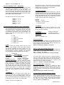
Zone type is the first digit entry. The zone types
and the value to enter are:
0
1
2
3
4
5
6
7
8
Once within the field, changes can be made by either:
A) Entering the appropriate two digit number or,
Memory Location
-
ENTRY - EXIT 1
ENTRY - EXIT 2
PERIMETER INST
INTERIOR 1
INTERIOR 2
INTERIOR 3
24 HOUR
FIRE 24 HOUR
DAY CIRCUIT
0 - ENTRY - EXIT 1 used for an Entry/Exit zone where
a delay is required to Enter or Exit the premises.
Two Digits number
1 - ENTRY - EXIT 2 may be used on entry exit zones
requiring longer periods of time, such as garage doors,
gates, outdoor detectors, etc. This zone type may also
be used in a partitioned system where a separate entry
or exit time is required for each partition.
B) By entering the number that corresponds to the
option that you wish to enable .
Memory Location
Zone Type
(Default:2)
Option Number
2 - PERIMETER INSTANT used for devices that
should create an instant alarm when the system is
armed in any mode.
3-4-5 - INTERIOR 1 - 2 - 3 used for devices such as
PIR, Ultrasonics, Mats, etc. that are used inside the
premises.
Example: If you depress 1-2-6 , the LCD will indicate
those three options have been enabled. Depressing a
number that previously was displayed will remove the
number from the LCD and disable the option
6 - 24 HOUR is used for devices that will activate an
alarm condition whether the panel is armed or
disarmed.
When the desired changes are made, simply depress
↑] button to lock the information in the EE prom
the [↑
and advance to the next memory field.
1
3440-0241 Rev G
creates a trouble (trbl) condition and will report a
trouble code if programmed. In an armed state, an
activation will create an alarm condition.
7 - FIRE ZONES are used for devices such as smoke
detectors (4 wire), heat sensor, water flow, etc. that
need to be active 24 hours.
8 - DAY CIRCUIT is used for devices such as window
foil, screens, etc. In a disarmed state, an activation
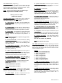
ARMING MODE
ENTRY/EXIT 1
and 2
Delayed Exit
Delayed Entry
PERIMETER
INSTANT
Delayed Exit
Instant
STAY
Delayed Exit
Delayed Entry
Delayed Exit
Instant
INSTANT
Instant Always
Instant Always
AWAY
INTERIOR #2
INTERIOR #3
Delayed Exit
Follower
or
Instant
Delayed Exit
Follower
or
Instant
Instant Always
Delayed Exit
Follower
or
Instant
Bypassed
Delayed
Delayed
Bypassed
Delayed
trouble (trbl) condition if programmed as loop type
three or four.
Value: 01 - FF, Default: 00 (Disabled).
LOOP TYPE is the second digit entry. The loop type
and value entered are:
0
1
*2
*3
INTERIOR #1
-
Normally Open
Normally Closed
Normally Open - Normally Closed
N.O. - supervised w/EOL - reports trouble on
break, alarm on short
* 4 - N.C. - supervised w/EOL - reports trouble on
short, alarm on open
ITEM F -Zone Features (MultipleEntries) Depressing
the number that corresponds to the option that you
wish to enable and it will also be displayed on the
LCD. Depressing a number that previously was
displayed will remove the number from the LCD and
disable the option.
NOTE: EOL resistor 2.2k ohm 1/2 watt
(Optex Part Number: 1401-4649).
ITEM A - Loop Response - Adjusted in two digit
increments in a multiplier of 50 ms. A longer loop
response may be required for devices such as water
flow detectors. A shorter loop response may be
required for devices such as glass break detectors.
Value: 00 - 99 x 50 ms., Default: 05 (250 ms.).
(Shows Default condition)
OPTIONS
1 = Telephone Output
2 = Audible
3 = Pulse Bell
4 = PGM 1
5 = PGM 2
6 = Walk Test
7 = Monitor
8 = Silent Day - Audible Armed
ITEM B - Alarm Code - (2 Digit Entry)
The panel will transmit this code when the zone
creates an alarm condition.
Value: 01 - FF, Default: 00 (Disabled).
ITEM C - Trouble Code - (2 Digit Entry)
This code that will be transmitted when a zone that is
programmed for a Loop Type three or four creates a
trouble condition.
Value: 01 - FF, Default: 00 (Disabled).
1 - TELEPHONE OUTPUT - is required to be enabled to
transmit all zone reporting codes. If the codes are
programmed and this function is not active, the zone report
codes will not transmit.
Default: YES
ITEM D - Bypass Code - (2 Digit Entry)
This code will be transmitted when the zone is
bypassed and the system is armed if the zone is
programmed for bypass allowed (see Item G)
Value: 01 - FF, Default: 00 (Disabled).
2 - AUDIBLE - must be enabled to energize the steady bell
voltage output If this function is not enabled the zone will
be silent. (See Item 58 for cutoff times.) Default: YES
Note: For Temporal Pattern Set Audible to Yes
3 - PULSE BELL - is required to be enabled to energize
the pulsing bell voltage output. Audible must also be
enabled to energize this function. Default: NO
NOTE: BYPASS SHOULD NOT BE ALLOWED
ON FIRE CIRCUITS.
Note: For Temporal Pattern Set Pulse Bell to Yes
ITEM E - Restore Code (2 Digit Entry)
This restore code is a common function that is
transmitted either after an alarm condition or after a
4 - PGM OUTPUT 1 - is an open collector that sinks to
ground for the amount of time that is programmed under
2
3440-0241 Rev G
Item 58. When this output is turned on as an alarm output,
it can not be used for any other function. See Item 58 for
cutoff times.
Default: NO
KEYPAD 1 - 2 - 3 - 4 - is a function that enables or
disables the keypad buzzer on entry. This function is only
active for Entry - Exit 1 or 2 type zones. The keypads are
always silent on alarm violation.
Default: YES.
5 - PGM OUTPUT 2 - is an open collector that sinks to
ground for the amount of time that is programmed under
Item 58. When this output is turned on as an alarm output,
it can not be used for any other function. See Item 58 for
cutoff times.
Default: NO
5 - DISPLAY ARMED - the zone will be displayed on the
LCD with this function on when a burglary zone is violated
in an armed state, If more than one zone is violated, they
will scroll on the LCD in numerical sequence.
Default: NO.
6 - WALK TEST - is a function that can be used by the
installer or the user. With this function enabled all zones
will be scrolling on the LCD. The zone number and name
will be removed from the LCD and the keypad will emit an
audible tone indicating the zone was violated. When all
zones have been tripped the LCD will display "NO MORE
FOUND".
Default: YES
NOTE: 24 Hour, Day Zone and Fire Zones are
active in this walk test mode.
6 - SHUNT ALLOWED - Used in conjunction with audible
set on for the zone.
When this option is used it prevents multiple code
transmissions from a swinging alarm condition. Regardless
of the number of trips, the panel will inhibit additional
signals, from this zone, until the bell times out. It will then
be ready to transmit subsequent events. Default: NO.
7 - BYPASS ALLOWED - Allows the subscriber to
manually bypass the zone if this option is set on.
Default: YES.
still
7 - MONITOR - is an option that allows local annunciation
of zone violation. See Item 76-B for output assignment for
this feature.
Default: YES
NOTE: This option should not be used on Fire zone.
8 - RADIO OUTPUT - This option enables the zone to
transmit its reporting codes via our Varitech long range
radio.
NOTE: 24 Hour, Day Zone and Fire Zones are active
in this mode and will only be displayed if
they are assigned for this option.
Once you have completed programming memory location OOG, the keypad will automatically advance you to memory
location 02 which is Zone 2.
Continue programming
information in the same manner as Zone 1 (memory location
00).
To exit back or review what was programmed in Zone 1
(memory location 00) depress [ # ]. The LCD will display PRG.
Then depress 00. To advance through each memory location
↑].
depress [↑
8 - SILENT DAY - AUDIBLE NIGHT - is an option that is
used with 24 hour zones that must be programmed for
audible. In a disarmed state, the violated 24 hour zone(s)
will enunciate on the LCD display, PGM 1 and/or PGM 2
will energize (if programmed as a zone output) and the
bell voltage will not energize. If this zone(s) is violated in
an armed state, PGM 1 and/or PGM 2 will energize, (if
programmed as zone outputs) and the bell voltage will
energize. Default: NO.
Memory Location 48 - 56C
COMMUNICATIONS PROGRAMMING
ITEM G This is a continuation of zone features and
also requires depressing the number that corresponds
to the option that you wish to enable and the number
will be displayed on the LCD. Depressing a number
that previously was displayed will remove the number
from the LCD and disable the option.
48 Receiver Telephone Number 1 (Panel will dial first)
Each memory location, from 48-48G, requires a 2 digit
entry. Beginning with Memory location 48 enter in a dial
pause (c) by depressing [AWAY] 2 and then the first digit
↑]. Continue until the
of the telephone number and [↑
telephone number is completely entered. Fill in the
remaining memory locations with (F) [AWAY] 5. The
maximum number of digits is sixteen, including dial pause
and dial tone detects.
For installations that require an access code to get an
outside line it's recommended to put a pause before and
after the access code. Example: C-9-C-3675951.
Value 0 - 9, A - D
Default: FF
(Shows Default condition)
OPTIONS
1 = KEYPAD 1 AUDIBLE
2 = KEYPAD 2 AUDIBLE
3 = KEYPAD 3 AUDIBLE
4 = KEYPAD 4 AUDIBLE
5 = DISPLAY ARMED
6 = SHUNT ALLOWED
7 = BYPASS ALLOWED
8 = RADIO OUTPUT
A
B
C
D
=
=
=
=
[AWAY]
[AWAY]
[AWAY]
[AWAY]
0
1
2
3
-
*
#
3 Second Pause
Dial Tone Detect
50 Receiver Telephone Number 2
Programmed in the same manner as Receiver number 1.
This receiver output can be used as back up or redundant
dialing and should always be programmed.
See
memory location 75 for your options.
3
3440-0241 Rev G
Value 0 - 9, A - D, Default: FF.
The reporting codes in this format must be single digit,
therefore you must enter a zero in the first memory location
followed by the code number to be transmitted.
Example: code 3, program 03.
52 Account Number 1 and 2 (2 Digit Entry)
When a reporting function is activated this account number
will identify the subscriber to the central station. In
memory location 52 will be the first two digits of the
account number and 52A will be the last two digits of the
first account number. 52B will be the first two digits of the
second account number and 52C will be the last two digits.
Value 0000 - FFFF, Default: 0000.
2 10 PPS 4-1 Extended
The digits are sent in the same manner as 4-1 but the
complete message consist of 2 rounds that will contain the
account number and the high digit of the message code.
This will be followed by two more rounds which will repeat
the high digit of the message code, in place of the account
number, and the low digit of the message code.
Hex digits can be used in accounts numbers:
[AWAY]
[AWAY]
[AWAY]
[AWAY]
[AWAY]
[AWAY]
+
+
+
+
+
+
0
1
2
3
4
5
=
=
=
=
=
=
A
B
C
D
E
F
Example:
Message : 1234-F5
Transmitted : 2 rounds of 1234-F
2 rounds of FFFF-5
3 10 PPS 4-2
This is a format that is similar in reporting as 4-1 EXT.
With the exception that the reporting is sent as two
identical rounds of information.
53 Receiver Formats for Receiver 1 and 2 (2 Digit Entry)
The first digit selects a format for Receiver number one.
The second digit selects a format for Receiver number two.
Many different types of central station receivers can accept
a multitude of formats. Naturally the format that “dumps”
the information the quickest is the most desirable. You
should consult with your central station to employ the
optimum format.
0
1
2
3
4
5
6
=
=
=
=
=
=
=
SIA
10 PPS
10 PPS
10 PPS
20 PPS
20 PPS
20 PPS
4 - 20 PPS 4-1
5 - 20 PPS 4-1 Extended
6 - 20 PPS 4-2
All three are the same
as 10PPS except at a
faster transmission speed.
Value 0 - 6, Default:: 1 - 1
4-1
4-1 extended
4-2
4-1
4-1 extended
4-2
53 A Anti-Jam Time
This is the amount of time required for the telephone company
to disconnect the phone line after the panel has hung up if it
was not "kissed" off on the first dialing attempt. Check with your
phone company for this value of time.
Value 00 - 99 seconds, Default: 15 seconds.
0 - SIA
SIA is an FSK type reporting format that has all the
reporting codes encoded in the control panel software.
The reporting capabilities are simply enabled when any
reporting code other than 00 are programmed in. (A code
00 will disable the reporting capability). The information
sent is predetermined by the activation of a zone type :
53 B Line Type / Dial Attempts (2 Digit Entry)
The first digit indicates the telephone line type for dialing the
central station. A zero selects Rotary (pulse) dialing while any
digit 1 - 9 will select tone dialing.
Value 0 = Rotary; 1-9 = Touch-tone, Default: 0 (Rotary).
EXAMPLES:
ZONE TYPE
MESSAGE SENT
All Interior / Perimeter
= Burglary + Zone Number
Fire zones
= Fire + Zone Number
24 Hour
= Burglary + Zone Number
Zone Restore (if used)
= Restore + Zone Number
10 and 20 PPS formats - The only difference between
these two formats is the speed and tone at which each
pulse of a digit in a message is transmitted. Both of these
formats will respond to 1400Hz or 2300Hz "handshake"
and "kiss off" tones. All of the 10 PPS formats are sent
using 1900Hz tones with a duration of 60 ms and a gap of
40ms for each pulse of a message digit. The 20PPS
formats are sent using 1800Hz tones with a duration of
30ms and a gap of 20ms for each pulse of a message
digit.
The second digit selects the number of dialing attempts to
report an event to the central station. If the communicator does
not receive a handshake and/or kissoff tone from the receiver, it
will disconnect and re-dial until the tone is heard or the
maximum number of attempts is reached.
Value 0 - 9, Default: 5. (minimum for UL 864)
53 C Delay Before Dial (2 Digit Entry)
This function enables the capability of aborting the alarm
transmission if the panel is disarmed within the period of time
programmed in this memory location. This function is active on
burglary zones only. All 24 Hour type zones will send their data
immediately.
Value 00 - 99 seconds, Default: 00 seconds.
1 10 PPS 4-1
This format requires a four digit account number with a
single digit event code. A complete message consist of 2
identical rounds account and message digits. In the event
that you have been assigned a three digit account number,
the first digit in memory location 52 must be a zero.
54 (A through G) Download Telephone Number
(Up to a 16 Digit Telephone Number)
This is a security function that when a call is initiated from a
Central Station download P.C. the panel will answer, recognize
the carrier tone from the modem, hang up the call, and call the
P.C. back. See memory location 48 for additional telephone
features. Value 0 - D, Default: FF.
Example: Account 123, program 0123.
4
3440-0241 Rev G
57 B Exit Delay #1 (2 Digit Entry)
This memory location works in conjunction with a zone type
programmed as Entry Exit Zone 1 (see zone type). The value
programmed in this memory location will allow a delay on exit
when the system is armed in AWAY or STAY modes.
Value 00 - 99 seconds, Default: 60 seconds.
56 Local Download PIN (4 Digit Entry)
This function works in conjunction with Download Telephone
Number (see Memory Location 54 A-G). The telephone
number must be programmed for this function to operate.
↑] is depressed, the panel will call
When this 4 digit number + [↑
the phone number programmed in memory location 54 A-G.
Value 0000 - 9999, Default: BLANK
NOTE:
57 C Exit Delay #2 (2 Digit Entry)
This memory location works in the same fashion as Exit Delay
#1 with the exception that this value is applied to Entry - Exit 2.
Value 00 - 99 seconds, Default: 60 seconds.
[Local Downloading] will be displayed when
remote down load has been activated.
56 B Download - Number of Rings (2 Digit Entry)
When a call is initiated from the P.C. the panel will answer the
call on this number of rings. Value 00 - 99, Default: 12.
Note: A separate entry exit delay period maybe selected for
each partition by programming a zone(s) for Entry Exit 1 to
a partition and zone(s) for Entry Exit 2 for the other
Partition. A partition may have more than one entry exit
zone.
56 C Download - Caller-ID (Telephone Company Option)
Compatibility Requires depressing the number that
corresponds to the option that you wish to enable and the
number will be displayed on the LCD. Depressing a number
that previously was displayed will remove the number from the
LCD and disable the option.
58 Pre-Alarm Delay (2 Digit Entry)
This function silences all keypad entry warning tones for the
amount of time programmed. This value adds on to the
entrance delay value. Example: 30 second pre alarm delay
(silent) + 60 entrance delay (audible) - total entry time = 90
seconds. Value 00 - 99 seconds, Default: 00.
The Telephone Company transmits the caller’s telephone
number between the first and second ring at the premises
where this feature is in service.
For the G-824 to be compatible with this service the line seizure
circuitry does not become active until after the second ring.
Note: This option delay's all keypads with partition
enabled.
58 A Bell Cutoff (2 Digit Entry)
The voltage will be present at terminals 28 (+) and 27 (-) for the
amount of time programmed in this memory location after an
alarm circuit trips and it has been programmed for AUDIBLE .
Value 00 - 99 minutes, Default: 10 minutes.
NOTES:
1. When this option is enabled, if on-premises telephone
is taken off hook prior to the second ring the panel will
not seize the line even if carrier is present at the time.
2.
When this option is Disabled, the line seizure circuitry
will become active after the first ring if carrier is
present. In this case the panel will seize the line, if
carrier is present, when an on-premises telephone is
taken off hook before the second ring.
NOTE: A value of 00 keeps this output energized until a
valid PIN is entered.
58 B PGM 1 Cutoff (2 Digit Entry)
This output will stay energized for the amount of time
programmed in this memory location after an alarm circuit trips
and it has been programmed to energize the PGM 1 output,
Value 00 - 99 minutes, Default: 0 minutes.
OPTION
1 = Disable caller-id feature
2 = Not Used
3 = Not Used
4 = Not Used
5 = Not Used
6 = Not Used
7 = Not Used
8 = Not Used
Memory Location 57 - 58C
ENTRY/EXIT DELAYS, OUTPUT CUTOFFS
57 Entry Delay #1 (2 Digit Entry)
This memory location works in conjunction with Entry - Exit 1
(see Zone Types). The value programmed in this memory
location will allow a delay on entry when the system is armed in
the AWAY or STAY arming modes.
Values 00 - 99 seconds, Default: 45 seconds.
57 A Entry Delay #2 (2 Digit Entry)
This memory location works in the same fashion as Entry Delay
#1 with the exception that this value is applied to Entry - Exit 2.
Value 00 - 99 seconds, Default: 45 seconds.
5
3440-0241 Rev G
58 C PGM 2 Cutoff (2 Digit Entry)
This output will stay energized for the amount of time
programmed in this memory location after an alarm circuit trips
and it has been programmed to energize the PGM 2 output,
Value 00 - 99 minutes, Default: 0 minutes.
01 - System Armed Status - When this option is selected,
this output will be present when the exit time has expired
and will remain until the system is disarmed.
NOTE: A value of 00 will keep PGM 1 and PGM 2 output
energized until a valid PIN is entered.
03 - Fail to Communicate - Can be used when the dialing
attempts have been exhausted that is programmed in
memory location 53 B. After the last dial attempt, this
output will be present until communication is restored.
02 - Not Used - for future use.
Memory Location 59 & 59B
PGM OUTPUT OPTION
04 - Follow Entry - Exit Delay - When this option is
selected, this output will be present for the amount of time
programmed in entry exit delay times
(see memory location 57).
59 PGM 1 Output Option (2 Digit Entry) PGM 1 Output can
be programmed to be used as one of the following functions:
The current available for this output is 20mA.
00 - Alarm Output - This option must be enabled when
used as a Zone Alarm Output. Output time follows value in
location 58 B.
05 - PGM 2 Output with Utility PIN - When this option is
selected you must also program the utility PIN in the user
program in memory location 2. When the utility PIN is
activated this output will be present for five seconds.
01 - System Status - If this option is selected PGM 1
output will be present when all zones are secured When
the system has been armed this output will not be present.
06 - Radio Key Output for Long Range Radio.- When
this option is selected , the Varitech radio key will be
produced.
02 - Ground Start - Can be used for a phone system that
requires a ground to be produced on either tip or ring to
bring up a dial tone. This output will be present for 2
seconds.
07 - Ring Back - When this option is selected this output
will be activated for two seconds after the open and close
report has been acknowledged. (See memory location 60)
08 - Partition Two Status - This option allows PGM-2
output to be utilized as an armed status indicator for
partition two.
Value 00 – 99 Default: 99 (Disabled)
NOTE: Additional hardware is required, see page 14 for
wiring diagram.
03 - Fail to Communicate - Can be used when the dialing
attempts have been exhausted that is programmed in
memory location 53 B. After the last dial attempt, this
output will be present.
NOTE: 09-99 Disables this Output
59B - PGM Output Options Requires depressing the number
that corresponds to the option that you wish to enable and the
number will be displayed on the LCD. Depressing a number
that previously was displayed will remove the number from the
LCD and disable the option.
04 - Follow Entry - Exit Delay - When this option is
selected, this output will be present for the amount of time
programmed in entry exit delay times
(see memory location 57).
OPTION
1 = PGM-1 on Two Wire Smoke Loop
2 = PGM-2 on Two Wire Smoke Loop
3 = PGM-1 on Keypad Fire
4 = PGM-2 on Keypad Fire
5 = PGM-1 on Keypad Panic
6 = PGM-2 on Keypad Panic
7 = PGM-1 on Keypad Emergency
8 = PGM-2 on keypad Emergency
05 - PGM 1 Output with Utility PIN - When this option is
selected, you must also program the utility PIN in the user
program in memory location 2. When the utility PIN is
activated this output will be present for five seconds.
06 - Long Range Radio Output - When this option is
selected, the audio data signal for Varitech (only) long
range radio transmission will be present at this output.
07 - Partition One Status - This option allows the PGM-1
output to be utilized as an armed status indicator for
partition one.
Value 00-99Default: 99 (Disabled)
1 - PGM-1 on Two Wire Smokes - This option allows
PGM-1 to energize when the two wire smoke loop detects
an activation . This output will stay active for the period of
time programmed in memory 58B or when a users PIN is
entered.
NOTE: 08-99 Disables this Option
2 - PGM-2 on Two Wire Smokes - This option allows
PGM-2 to energize when the two wire smoke loop detects
an alarm activation . This output will stay active for the
period of time programmed in memory location 58C or
when a users PIN is entered.
59 A PGM 2 Output Option (2 Digit Entry) PGM 2 Output
can be programmed to be used as one of the following
functions: The current available for this output is 20mA.
00 - Alarm Output - Is used in conjunction with Zone
Output. Output value follows time in location 58 B.
6
3440-0241 Rev G
arming the system. Example: 02 Programmed. Code 2 will
be transmitted, the 0 will be dropped as an inconsequential
digit. Value 01 - FF, Default: 00 (Disabled).
3 - PGM-1 Keypad Fire - This option allows PGM -1 to
energize when the keypad fire is activated .This output will
stay active for the period of time programmed in memory
location 58B or when a users PIN is entered.
68 Auto Arm Report Code (2 Digit Entry)
When the auto arm function enabled (see users program,
memory location 4) this code will be transmitted to the central
station if the panel was successful in performing an auto arm.
Value 01 - FF, Default: 00 (Disabled).
4 - PGM-2 KEYPAD FIRE - This option allows PGM-2 to
energize when the keypad fire is activated . This output will
stay active for the period of time programmed in memory
location 58C or when a users PIN is entered.
5 - PGM-1 KEYPAD PANIC - This option allows PGM-1 to
energize when the keypad panic output is activated . This
output will stay active for the period of time programmed in
memory location 58B or when a users PIN is entered.
NOTE: If a zone is left violated the system will not perform
an auto arm.
68 A Fail to Auto Arm Report Code - (2 Digit Entry)
When the auto arm function is enabled (see user program
memory location 4) this code will be transmitted if the panel is
unsuccessful in performing an auto arm.
Value 01 - FF, Default: 00 (Disabled).
6 - PGM - 2 KEYPAD PANIC - This option allows PGM-2
to energize when the keypad panic output is activated .
This output will stay active for the period of time
programmed in memory location 58C or when a users PIN
is entered.
68 B Duress Report Code - (2 Digit Entry).
When the duress PIN (see Memory location 78B) is enabled,
this report code will be transmitted to the central station (either
on arming or disarming).
Value 01 - FF, Default: 00 (Disabled).
7 - PGM-1 KEYPAD EMERGENCY - This option allows
PGM-1 to energize when the keypad emergency output is
activated . This output will stay active for the period of time
programmed in memory location 58B or when a users PIN
is entered.
68 C AC Fail Report Code - (2 Digit Entry).
In the event of an AC failure , this is the code that will
transmitted. This code will be transmitted when the panel
recognizes the battery has depleted 25% of the standby current
and no greater than 50%.(See Battery Calculations - Page 16)
8 - PGM - 2 KEYPAD EMERGENCY - This option allows
PGM-2 to energize when the keypad emergency output is
activated . This output will stay active for the period of time
programmed in memory location 58C or when a users PIN
is entered.
69 AC. Restoral Report Code - (2 Digit Entry).
This code will report 3 minutes after AC is restored.
NOTE : The options listed above for memory location 59B
will function only if ALARM OUTPUT operation has been
selected in memory locations 59 for PGM-1 options and
59A for PGM-2 options .
69 A Low Battery Report Code - (2 Digit Entry).
IIf the battery voltage drops to 10.4 Volts , this code will be
transmitted.
See Battery Calculations - Page 16
Memory Location 60 - 72C
MISCELLANEOUS REPORTING CODES
69 B Battery Restore Report Code - (2 Digit Entry).
This code will be transmitted when the battery voltage returns
to 10.5 volts or greater.
See Battery Calculations - Page 16
60 - 63 User Open Code (2 Digit Entry)
The system is capable of transmitting sixteen individual
opening report codes. Normally the first digit entered identifies
the event (in this case open code) followed by a numeric
identifier. Example: 20 = Open Code, 1 = User #1. Program
for User #1 = 21.
When using this reporting scheme the central station must be
able to receive either a 4-1 extended or 4-2 format.
When using a 4-1 format a 2 digit entry is still required. The
second digit entered is the code that will be transmitted on
disarming the system. Example: 01 Code programmed. Code
1 will be transmitted, the 0 will be dropped as an
inconsequential digit.
Value 01 - FF, Default: 00 (Disabled).
69 C Box Tamper Report Code (2 Digit Entry)
This report code will be transmitted to the central station when
the cabinet tamper is violated and the box tamper function is
enabled (see memory location 76A)
Value 01 - FF, Default: 00 (Disabled).
70 Box Tamper Restore Report Code (2 Digit Entry)
This code will be transmitted to the central station when the
cabinet tamper is reset,
Value 01 - FF, Default: 00 (Disabled).
70 A Bell Fault Report Code (2 Digit Entry)
This code will be transmitted when a break or short occurs in
the bell circuit.
64 - 67 User Close Code (2 Digit Entry)
The system is capable of transmitting sixteen individual closing
report codes. Normally the first digit entered identifies the
event (in this case the close) followed by a numeric identifier.
Example: 30 = Close Code, 1 = User #1. Program for User #1
= 31.
When using this reporting scheme the central station must be
able to receive either a 4-1 extended or 4-2 format.
NOTE: 2.2k end of line resistor must be installed at the bell.
When using the G-FM3 (Required for UL fire) this code will be
transmitted when a break or short is detected in the bell circuit.
When using a 4-1 format a 2 digit entry is still required. The
second digit entered is the code that will be transmitted on
7
3440-0241 Rev G
70 B Auxiliary Power Fault Report Code (2 Digit Entry)
This code will be transmitted to the central station if the
auxiliary power fuse is open.
Value 01 - FF, Default: 00 (Disabled).
73 Expander Zone Definition (2 Digit Entry)
This location determines the number of Expander Boards (GEX) that are installed. The choices are as follows:
70 C Keypad Fire Report Code (2 Digit Entry)
This code will be sent to the central station when "STAY AND
"6" are pressed simultaneously for approximately 2 seconds
then the buttons are released.
(see memory location 76A)
Value 01 - FF, Default: 00 (Disabled).
00 No zone expansion board on bus
01 G-EX number 1 installed .
02 G-EX number 1 & 2 installed .
03 Not Used / Future Use
04 Not Used / Future Use
05 Not Used / Future Use
06 Not Used / Future Use
07 Not Used / Future Use
Default: (00) No Expansion Board
71 Keypad Emergency Report Code
This code will be sent to the central station when "INSTANT"
AND "9" are pressed simultaneously for approximately 2
seconds when the buttons are released.
(see memory location 76A)
Value 01 - FF, Default: 00 (Disabled).
If you have selected this option without installing the
expander boards the keypad will indicate a "Bus Failure"
trouble and transmit a Bus Fault report code. This G-EX(s)
must also be addressed by removing the appropriate
shorting links. (see wiring diagram) (see memory location
73B). Value 01 - 02, Default: 00 (Disabled).
71 A Keypad Panic Report Code
This code will be sent to the central station when "AWAY"
and "3" are pressed simultaneously for approximately 2
seconds when the buttons are released.
(see memory location 76A)
Value 01 - FF, Default: 00 (Disabled).
73 A Keypad Installed/Partitions - Requires depressing the
number that corresponds to the option that you wish to enable
will be displayed on the LCD. Depressing a number that
previously was displayed will remove the number from the LCD
and disable the option.
71 B Open Restore Report Code (2 Digit Entry)
This report code will be transmitted when the system has
been disarmed after an alarm condition has been occurred.
Value 01 - FF, Default: 00 (Disabled).
OPTIONS
1 = KEYPAD 1
2 = KEYPAD 2
3 = KEYPAD 3
4 = KEYPAD 4
5 = KEYPAD 1
6 = KEYPAD 2
7 = KEYPAD 3
8 = KEYPAD 4
71 C 2 Wire Smoke Detector Report Code - (2 Digit Entry)
This report code will be transmitted to the central station
when the 2 wire smoke detector circuit senses an alarm
condition. (terminals 26 and 25).
Value 01 - FF, Default: 00 (Disabled).
72 Fire Trouble Report Code (2 Digit Entry)
This report code will be transmitted to the central station
when a trouble is detected on the 2 wire smoke detector
loop.
Value 01 -FF, Default: 00 (Disabled).
Always ON
for partition 1
for Partition 1
for Partition 1
for Partition 1
One through four are enabling the number of keypads that
are going to be used.
Five through eight are assigning the keypads to a partition. If
the number is displayed, that keypad will be assigned to
partition number one. If the number is not displayed, that
keypad will be assigned to partition number two (see memory
location 76A).
72 A Fire Restore Code - (2 Digit Entry)
This reporting function is a common restore code for both
Fire Alarm and Fire Trouble on the 2 wire smoke detector
circuit. This report code will be transmitted to the central
station after a fire alarm or fire trouble has been reset.
Value 01 - FF, Default: 00 (Disabled).
73 B Buss Fault Report Code (2 Digit Entry)
This report code will be transmitted to the central station if a
open or short is detected on the keypad buss.
Value 01 - FF, Default: 00 (Disabled).
72 B Bell Restore Code (2 Digit Entry)
This report code will be transmitted when the bell circuit has
reset and the zone has been secured after an alarm
condition. The code will not be transmitted until the zone is
secured , even though the bell circuit has reset.
Value 01 - FF, Default: 00 (Disabled).
73 C Charge Time - High & Low (2 Digit Entry)
Add total current draw of the system including control panel,
keypad(s) and auxiliary devices. Use the following table to
get digits for location 73C.
72 C Ground Fault Report Code (2 Digit Entry)
This report code will be transmitted to the central station
when the supervised earth ground is lost on the G-FM3.
(see memory location 76)
Value 01 - FF, Default: 00 (Disabled).
Memory Location 73 - 74
EXPANDERS, KEYPADS AND PARTITIONS
8
3440-0241 Rev G
TOTAL SYSTEM
CURRENT (mA)
00 - 100mA
101 - 200mA
201 - 300mA
301 - 400mA
401 - 500mA
501 - 600mA
601 - 700mA
701 - 800mA
801 - 900mA
DIGIT TO ENTER
IN LOCATION 73C
1
2
Report only to receiver number 2
Report first to receiver number 1, if not successful,
attempt to report to receiver number 2
3
Report to receiver number 1 and receiver number 2
4
No Telco reporting for System messages
Value 0 - 4 Default: 0
91
92
93
94
95
96
97
98
99
The second digit selects reporting of codes on Long-range
radio.
Value
0
Function
No radio out put for open/close, system test, or
system messages
1
open/close on radio
2
system test code on radio
3
open/close + system test codes on radio
4
system messages on radio
5
system message + open/close on radio
6
system message + system test on radio
7
system message + system test + open/close on
radio
Value 0 - 7 Default: 0
74 Abnormal Self Test Report Code (2 Digit Entry)
This communicator test report code will be transmitted in place
of the self test code programmed in memory location 77C
should a fire zone or the two wire smoke detector loop be left in
an alarm or trouble condition .
NOTE: This must be used to comply with UL864.
74A Telephone (TLM) Fault report code (2 Digit Entry)
This code will be sent whenever a telephone line fault is
detected. (See also memory location 76-6)
Value 00 - FF.Default: 00 (Disabled)
75 B Communication Fail Report Code (2 Digit Entry)
The Communication Fail Report Code is transmitted when the
panel has exhausted its dialing attempts
(see memory location 53B).
Value 01 - FF, Default: 00 (Disabled).
Memory Location 75 - 75C
SIGNAL ROUTING
Note: Must use "Two phone lines" or "One phone line and
Long range radio".
75 Receiver Reporting for Alarm & Restores - Open &
Close (2 Digit Entry)
If you have been assigned to only one telephone number and
account number, duplicate the receiver information and select
option 2 for memory locations 75 and 75A.
The first digit tells the panel which receiver or receivers to direct
the alarm and restore report codes.
Value 0 - 4, Default: 0.
Value
0
1
2
3-4
75 C Number of Radio Attempts
The number of times the event is transmitted via Varitech long
range radio.
Value 00 - 09 units Default: 00 (Disabled)
Memory Location 76 - 79C
SYSTEM FEATURES
Function
Report only to receiver number 1
Report only to receiver number 2
Report first to receiver number 1, If not successful,
attempt to report to receiver number 2
Report to receiver number 1 and receiver number 2
76 System Features (Multiple Entries) requires depressing
the number that corresponds to the option that you wish to
enable and the number will be displayed on the LCD.
Depressing a number that previously was displayed will remove
the number from the LCD and disable the option.
The second digit tells the panel which receiver or receivers to
direct the open and close report code to.
Value 0 - 4, Default: 0.
Value
0
1
2
3
4
Function
Report only to receiver number 1
Report only to receiver number 2
Report first to receiver number 1, if not successful,
attempt to report to receiver number 2
Report to receiver number 1 and receiver number 2
No reporting for receiver number 1 or number 2
Shows Default condition : All OFF
OPTIONS
1 = Bell Test
2 = Bell Audible on Bus Fault
3 = Digital first & Radio second
4 = G-FM3 Installed
5 = 50 Hz
6 = Telephone Fault(TLm)Monitoring enable
7 = System test to be reported on Telco
8 = Partition System
1 - Bell Test With this option selected, the bell voltage will
be present for three seconds when the control panel is
armed. Default: NO
75 A System Report Code (2 Digit Entry)
The first digit tells the panel which receiver or receivers to direct
the housekeeping signals (power codes, failure codes, keypad
triggered alarm codes, etc.).
Value 0 - 9, Default: 0.
Value
0
Function
Report only to receiver number 1
2 - Bell Audible on Bus Fault With this option selected
the bell voltage will energize should the panel detect a fault
9
3440-0241 Rev G
on the Buss for the amount of time programmed in memory
location 58A or until a valid PIN is entered in the keypad.
Default: NO
report+bell =
report code(see memory location 71A)+
Panic audible (see below)
3 - Keypad Fire Enabled with this option selected the
keypad fire function is enabled ("STAY" and "6"). You may
have this function set for silent or audible or both.
Default: NO
3 - Digital first & Radio second With this option selected
the digital signal will be transmitted first and if it is
successful, the radio signal will not be sent.
Default: NO
4 - Keypad Fire Audible with this option enabled, the
keypad fire will be audible. Default: NO
4 - G-FM3 Installed With this option selected the panel will
recognize the G-FM3 (Fire Module) installed and will
indicate a bus fault should the G-FM3 fail or be removed
from the system. Default: NO
silent only =
bell only =
report+bell =
5 - 50 Hz or 60 Hz This option is very important to be set
correctly to insure proper operation of the time clock. The
default is set for US operation (60Hz). To set the system
for 50Hz, the number 5 should be showing on the LCD.
Default: 60 Hz
report code (see memory location 70C).
no report code + fire audible (see below)
report code(see memory location 70C)+
Fire audible (see below)
5 - Keypad Emergency Enable with this option selected
the keypad emergency function is enabled ("INSTANT"
and "9".). You may have this function set for silent or
audible or both. Default: NO
6 - Telco Fault Monitoring Enable With this option
selected, the keypad will give a visual indication of a
telephone trouble (TLM) and emit a pulsing audible tone
from keypad. Default: NO
6 - Keypad Emergency Audible with this option enabled,
the keypad emergency will be audible. Default: NO
silent only = report code (see memory location 71).
bell only = no report code + emer. audible (see below)
report+bell = report code(see memory location 71)+
emergency audible (see below)
7 - System Test to be Reported on Telco With this option
selected the panel will automatically transmit the signal to
the central station on the telco line. Default: YES
7 - Key switch or Tamper Inputs When the key switch
option is selected terminals 7 and 10 will support any
momentary or latching arming station. The number 7
should be displayed on the LCD to select the key switch
input. The number 7 should not be displayed if you need to
use as a tamper switch. A report code must be
programmed in memory location 69C when selected for
tamper switch input, This tamper input is silent only.
Default: Tamper Switch
8 - Partition System With this option selected the panel
can be used as two separate systems. The first half of the
zones will automatically become partition number 1 and
the second half of the zones will become partition number
2. PIN's one through eight automatically become assigned
to partition number one and PIN's nine through sixteen will
become assigned to partition number two.
Partition
number one will always report its information to Receiver
number one including open and close signals and partition
number two will always report its information to receiver
number two including open and close signals. The house
keeping signals (AC fail, low batt., etc.) report to receiver
one. (See memory location 48 through 53.) Default: NO
8 - AC Fail Audible on Keypad Should there be a loss of
AC power, this option will enable an audible tone to emit
from all keypads, together with AC trouble display on the
LCD. Only AC trouble will display on the LCD if this option
is not selected.
Default: NO
76 A System Features (Multiple Entries) Requires depressing
the number that corresponds to the option that you wish to
enable and will be displayed on the LCD. Depressing a number
that previously was displayed will remove the number from the
LCD and disable the option.
76 B Monitor Mode Features (Multiple Entries)
Requires depressing the number that corresponds to the option
that you wish to enable and the number will be displayed on the
LCD. Depressing a number that previously was displayed will
remove the number from the LCD and disable the option.
(See next page).
OPTIONS
1 = Keypad Panic Enabled
2 = Keypad Panic Audible
3 = Keypad Fire Enabled
4 = Keypad Fire Audible
5 = Keypad Emergency Enabled
6 = Keypad Emergency Audible
7 = Key switch or Tamper Inputs
8 = AC fail Audible on Keypad
1 - Keypad Panic Enabled With this option selected the
keypad panic function is enabled ("AWAY" and "3"). You
may have this function set for silent or audible or both.
Default: NO
2 - Keypad Panic Audible with this option enabled, the
keypad panic will be audible. Default: NO
silent only =
bell only
=
report code (see memory location 71A).
no report code + panic audible (see below)
10
3440-0241 Rev G
2 = Auto. Monitor on Disarm
3 = Key switch Operation
4 = Force Arming
5 = Common PIN
6 = not used
7 = not used
8 = not used
OPTION
1 = Acknowledge required for monitor mode
2 = Bell output for monitor mode
3 = PGM 1 output for monitor mode
4 = PGM 2 output for monitor mode
5 = Bell output for walk test mode
6 = Bell output for TLM fault in armed condition
7 = 2 wire smoke alarm verification
8 = Steady bell on 2-wire smoke and keypad fire
1 - Hide Display Clock If selected clock will not be
displayed, but current system status mode will be
displayed.
Default: NO
1 - Acknowledge Required When a zone is violated in
the monitor mode with this option selected, the zone
number will stay in the display until the zone is secured
and the keypad and/or audibles will emit a continuous
↑] key is depressed or a valid PIN is entered.
tone until the [↑
If this option is not selected the keypad will emit a 2
second tone and the zone will continue to display until the
zone is secured. Default: NO ACK
2 - Automatic Monitor on Disarm This option allows the
control panel to automatically enter into in the monitor
mode when the system is disarmed if there have been no
alarm activation. Should an alarm been activated, the
panel must present the memory to the subscriber and then
be manually put into the monitor mode. See memory
location 76B for additional monitor mode options.
Note: This option is not available with partitioned systems.
Default: NO
2 - Bell Output for Monitor Mode With this option is
enabled, the bell voltage will energize when the panel is
put into the monitor mode and a zone that is assigned to
the monitor mode, is violated. Default: NO
3 - Key Switch Operation This option allows the control
panel to accept a latching or momentary closure across the
key switch input (terminals 7 & 10) to arm the system. For
latching operation the number must be present. See
memory location 76A for additional key switch
programming option .
Default: Momentary
3 - PGM 1 Output for Monitor Mode With this option is
enabled, the PGM-1 will energize when the panel is put
into the monitor mode and a zone that is assigned to the
monitor mode, is violated. Default: NO
4 - PGM 2 Output for Monitor Mode With this option is
enabled, the PGM-2 will energize when the panel is put
into the monitor mode and a zone that is assigned to the
monitor mode, is violated. Default: NO
4 - Force Arming This option allows the key switch input
to force arm the control panel. The key switch input must
be programmed for a latch mode operation. (see above
option) See memory location 76A for additional key switch
programming option .
Default: No
5 - Bell Output for Walk Test Mode With this option
selected Bell activates for one second when a zone is
activated in the walk test.
5 - Common Pin This option allows user number one
PINs' to disarm both partition one and partition two. See
memory location 76 for partition system .
Default: no
6 - Bell Output for TLM Fault in Armed Condition With
this option selected the panel will activate the bell output
and emit a pulsing audible tone from keypad along with
indication of [TLM fault]. If the system is configured for
Radio, it generate common fail signal.
77 Self Test Time Interval (Hours)
A memory location where the hours of a day the self test code
will be transmitted to the central station. The value entered in
this location must be 2 digits. The hours must be entered in
military time. Example: 3:00 PM - Program 15.
Value 00 - 23, Default: 99 (disable).
7 - 2 Wire Smoke Alarm Verification When this feature
is enabled the panel will automatically reset the power to
the two wire smoke detectors upon receipt of an alarm
signal. The reset time is a predetermined period in
accordance with UL requirements. If the detector returns to
an alarm condition, when power is re applied, the panel will
initiate the appropriate reporting as programmed.
77 A Self Test Time Interval (Minutes)
A memory location where the minutes of the hour the self test
code will be transmitted. Example: test at 3:30 PM = 15:00
hours, 30 minutes. Value 00 - 59 minutes, Default: 99.
8 - Steady Bell Output for 2-wire smoke & keypad fire If
selected, bell output will be steady for programmed time on
2-wire smoke alarm & keypad.
77 B Self Test Time Interval (Days)
This memory location indicates the interval between days the
panel will transmit the self test code to the central station.
Value 01 - 99, Default: 00 (Disabled)
76C - System Features (Multiple Entries) Requires
depressing the number that corresponds to the option that
you wish to enable and the number will be displayed on the
LCD. Depressing a number that previously was displayed
will remove the number from the LCD and disable the
option.
77 C Self Test Report Code (2 Digit Entry)
When the self test time occurs this report code will be
transmitted to the central station.
Value 01 - FF, Default: 00 (Disabled).
78 Installers PIN (4 Digit Entry)
This memory location is very important. Record this PIN in a
secure location. Call the factory should this PIN be lost.
Value 0000 - 9999, Default: 9999
OPTION
1 = Hide Clock
11
3440-0241 Rev G
The zone number you wish to program should be entered as
↑) will lock in your selection
two digits (o1-24). Pressing the (↑
and the LCD will change to read:
78 A Duress PIN (4 Digit Entry)
This PIN will arm or disarm the system and will transmit the
duress report code (see memory location 68B) to the central
station. Value 0000 - 9999, Default: BLANK.
ENTER ZONE #
ZONE ONE
NOTE: PIN's (installer, duress, user) cannot be duplicated.
If a duplicate PIN is attempted to be programmed
an audible from the keypad will indicate the PIN
has been rejected.
(ZONE ONE was used only as an example)
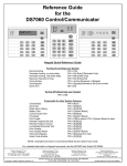
At this point you may now begin entering the alpha text you
wish by selecting the number that corresponds to the letter or
↑) after
character from the chart on page. You must press (↑
each of your selections to lock in the letter and this will
automatically advance the cursor to the next character. Once
editing of the zone name have been completed, you must
press (INST) to lock your selection into memory. If (INST) is not
pressed, the name will revert to the factory default: settings.
79 - 79 A Battery Charging Calculations
BATTERY CALCULATIONS
To comply with UL requirements the primary power failure
trouble signal for the communicator shall not be
transmitted until the standby power capacity is at least 25
percent depleted, but not more than 50 percent.
Therefore, it is necessary to program these two memory
locations with the total current available (subtract total
current draw of panel, keypad(s), expansion modules and
other auxiliary devices powered from auxiliary power from
total current capacity) and amp-hour rating of battery to be
used.
79)
1000 mA - Total current in mA
10
After (INST) is pressed, the LCD will now request another zone
number be entered. Repeat the above procedure until all zones
have been named.
Once all zones have been named, press (#) once to return to
the main installers program mode. Pressing the (#) a second
time will return the User's operating mode.
PROGRAMMING HINTS:
= XX
↑). The cursor will delete
1)To enter a space, simply press the (↑
the previous character (if anything) and advance to the next
character.
Convert XX in Hex Chart 1 and enter in 79.
79 A)
AH Batt x 10 = YY
2) To move about the location without deleting the characters,
press (AWAY) to move right or press (STAY) to move left.
Convert YY in Hex Chart 1 and enter in 79 A.
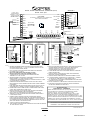
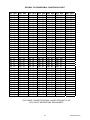
WIRING INSTRUCTIONS
NOTE 1:
LOW BATTERY CODE is transmitted when:
1) there is no battery connected;
2) the battery fuse is open;
3) the battery voltage goes below approximately
11.5 VDC.
TERMINALS
NOTE 2:
GOOD BATTERY is transmitted when the battery
voltage reaches approximately 12 VDC.
79B First 2 digits of Panel Access ID for RPU
(Remote Programming Utility)
79C Last 2 digits of Panel Access ID for RPU
1&2
16 VAC Class II plug-in transformer (20 VA
maximum). Use 18 GA twisted or zip pair and keep
wire run as short as possible. Test the electrical
outlet being used to ensure it is not controlled by a
light switch. (24 hour source)
3-4-5-6
Data bus inputs - These terminals are used for
wiring in keypads (maximum 4), expansion modules
(maximum 2), and G-FM3. The keypads and
expansion modules can be wired in either a daisy
chain or homerun configuration. Each keypad must
be addressed by setting the two dip switches
located on the back of each keypad. Maximum
cable length 1,000 feet.
Memory Location
80 - 95
NOT USED / FUTURE USE
ALPHA PROGRAMMING INSTRUCTION
The alpha programming of the control panel is accessed by
↑) 7 & (AWAY). The LCD will
entering the installers PIN (↑
change to: ENTER ZONE #.
12
3440-0241 Rev G
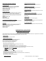
KEYPAD
1
2
3
4
7-11-12
7-9
8-9
7 - 10
SWITCH
1
2
on
on
on
off
off
on
off
off
a) If programmed as a 24 Hour zone and for trouble
report - the audible in the keypad will sound and the
communicator will transmit the trouble code to the
central station.
b) If programmed as a controlled zone (Day/Night)
and for Trouble report - the audible in the keypad
will sound if the system is disarmed.
PGM-1 and PGM-2 outputs are open collector
outputs - Terminal 7 is the positive voltage output
and Terminal 11 is the negative output of PGM-1.
Terminal 7 is the positive voltage output and
Terminal 12 is the negative output of PGM-2. The
maximum current available for these two outputs is
20 mA each. When PGM-1 and or PGM-2 are
triggered, these outputs go low.
If the system is armed the audible in the keypad will
sound and the communicator will transmit the
trouble code to the central station.
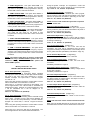
4 NORMALLY CLOSED with TROUBLE REPORT
on SHORT: This loop requires an end of-line
resistor (2.2 K ohms) and detection devices or
switches that "open" on alarm. A short will produce:
Auxiliary power outputs - Terminal 7 is positive
voltage output and Terminal 9 is negative voltage
output. These terminals provide a continuous 12
volt output. These terminals should be used for any
device that doesn't require an interruption of power
to reset an activation.
a) If programmed as a 24 Hour zone and for trouble
report - the audible in the keypad will sound and the
communicator will transmit the trouble code to the
central station.
Switched power output Terminals 8 is a positive,.
Terminal 9 is negative.
b) If programmed as a controlled zone (Day/Night)
and for Trouble report - the audible in the keypad
will sound if the system is disarmed.
If any zones are configured as fire zones, the power
is derived from these terminals. If a fire zone is
activated, the user enters his PIN and terminal 8 will
go low for ten seconds.
If the system is armed the audible in the keypad will
sound and the communicator will transmit the
trouble code to the central station.
25(-) 26(+) Two wire smoke detector loop. These 2 terminals
are used in conjunction with ESL Model 425 series.
If there is an activation on this loop entering a valid
↑] + [2] will reset this loop. Maximum
[PIN] + [↑
number of approved smoke detectors that can be
used on this loop is ten (10). Refer to wiring
diagram for list of approved smoke detectors.
Tamper N.C. or Key switch inputs - This input is a
programmable option. See installation and
programming manual - memory location 76A. When
programmed as a tamper switch input the input will
always be silent. When programmed as a key
switch input, a momentary close is required. The
panel will always arm in an away mode, when a key
switch is used.
The keypad will display [FIRE] when this input trips.
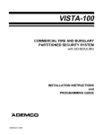
13 thru 24 Protection loops - Zones 1 through 8 are
connected to these terminals as indicated in Fig. 1.
Note: Heat detectors, Do not use Water flow
switch or Any other device on this circuit. Only
the two wire smoke detector loop may used to
comply with UL864.
All loops are two wire and may be wired as the
following "Loop Types":
O NORMALLY OPEN: This loop requires the use
of detection devices or switches that close (short) on
alarm.
27(-) 28(+) Bell voltage output - 12 VDC is provided on these
terminals. The maximum amount of current
available is 2 amps. For supervision of the bell
circuit, a Fire Module (G-FM3) must be used.
1 NORMALLY CLOSED: This loop requires the
use of detection devices or switches that open on
alarm.
29 through 32 Telephone line connection - The Genesys
824 provides for single phone line hookup with full
line seizure. To expand to two line use the Fire
Module (G-FM3) must be used.
2 NORMALLY OPEN and NORMALLY CLOSED:
This loop requires an end-of-line resistor (2.2 K
ohms) and will accept both types of switch operation
(open or closed).
TERM
TERM
TERM
TERM
3 NORMALLY OPEN with TROUBLE REPORT
ON BREAK: This loop requires an end of-line
resistor (2.2 K ohms) and detection devices or
switches that "close" (short) on alarm. An open
condition (loss of 2.2 K ohms resistor) will produce:
13
29
30
31
32
PREMISE RING
PREMISE TIP
TELCO RING
TELCO TIP
RJ JACK
GRAY
BROWN
RED
GREEN
PIN
1
8
4
5
3440-0241 Rev G
16.5VA C , 20VA
TR A N S F O RM E R
(C O N N E C T TO 24 H R . 1
POW ER SOURCE)
2
S E E N O T E 18 & 19
AC
IN C O R R E C T TE RM IN A L B LO C K C O N N E CT IO N
M AY D A M A G E E Q U IP M E N T.
GRN
5
C LK
BLK
6
GND
7
AUX+
8
SW AUX+
9
GND
GRN
R IN G
31
RED
T IP
30
G RY
R IN G
29
BRN
1
2
3
4
5
6
B E L L+
28
B E LL -
27
SMOKE+
26
SMOKE -
25
MO MMOC
12 VOLT
BATT
_
+
MOMMOC
PGM2
AUX FUSE
2 AMP
MO MMOC
12
PREM
MOMMOC
PG M 1
32
7
GND
K E YPA D
M O D EL G -K P A lpha
M O D E L G -KP
R ED
M O D E L G -F M 3
S U P E R V IS E D F IR E M O D U L E
M O D E L G -E X
Z O N E E X PA N D E R
J1
RF-RM1
RADIO TRANSMITTER
2
10
1.2K
10
11
12
AUX+
SW AUX+
P1
1
J1
2
3
3
4
4
5
5
J1
B E L L PA N + 16
B E L L PA N - 15
J2
6
J2
7
J3
7
J3
E A R T H G N D 13
BELL+ 12
11
BELLTELCO
PA N
10
9
9
P R E M IS E S
PHONE 2
8
8
8
AUX IN
9
PGM1
10
10
T E L C O IN 2
PGM2
11
11
P R E M IS E S
PHONE 1
12
P2
P1
12
CONNECT EXTERNAL UL LISTED
POW ER SUPPLY IF NEEDED. (NOTE 17)
TO CONTROL PANEL TERM.28
TO CONTROL PANEL TERM.27
COLD
W AT E R
P IP E
14
6
GND
(RADIO APPLICATION SHOWN)
3
2
1
B E LL P W R - 18
B E L L P W R + 17
P2
P1
NOTE:
1. MAXIMUM COMBINED POWER AVAILABLE ON 824 CONTROL PANEL
INCLUDING TERMINALS 4, 6, 7, 8, 26, 27, AND 28 IS 750 mA AT 12 VDC.
ALL CIRCUITS ARE POWER LIMITED.
2. USE 2.2 KOHM 1/2 WATT RESISTORS FOR ZONES THAT REQUIRE
EOL (ZONE TYPE 2, 3 AND 4).
3. BELL AND 2-W IRE SM OKE ZONES REQUIRE 2.2K OHM
FIRE EOL RESISTORS. OPTEX PART NUM BER 5090-0255.
4. THE OPERATING VOLTAGE RANGE FOR SMOKE DETECTOR
TERMINALS IS 9.3 TO 14.8 VOLT.
5. ZONE EXPANDER G-EX BOARD IS CONFIGURED AS ZONE TO ZONE 16
W HEN JUMPER J1, J2, AND J3 ARE LEFT OPEN.
THE BOARD IS CONFIGURED AS ZONE 17 TO ZONE 24 W HEN J1, J2 ARE
LEFT OPEN AND J3 IS SHORTED.
6. COMMUNICATION BETW EEN CONTROL PANEL G-EX AND G-FM3 IS
MADE THROUGH 4-W IRE CONNECTIONS AS SHOWN. CABLE ASSEMBLY
IS PROVIDED.
7. PGM1 AND PGM2 ARE OPEN COLLECTOR OUTPUTS THAT GO LOW TO
APPROXIMATELY 2V WHEN ACTIVATED. MAXIMUM CURRENT: 20 mA.
8. BOXED AREA SHOW S PHONE AND BELL CONNECTIONS WHEN G-FM3
IS NOT USED. DISREGARD IF USING G-FM3.
9. REFER TO BATTERY CALCULATION CHART IN INSTALLERS MANUAL
(3440-0241) FOR CORRECT AMP-HOUR BATTERY.
FOR UL FIRE APPLICATIONS USE DUAL BATTERY CABLE (60118)
10. TERMINALS 7 AND 10 MUST BE USED FOR CABINET TAMPER FOR UL
LISTED INSTALLATIONS.
11. CONNECT EARTH GROUND TO RIGHT SIDE MOUNTING SCREW.
FOR UL FIRE APPLICATION DO NOT USE THIS MOUNTING SCREW FOR
EARTH GROUND! INSTEAD CONNECT TERMINALS 13 & 14 OF G-FM3 TO
COLD WATER PIPE AND USE THE ENCLOSED MOUNTING KIT IN G-FM3
(SEE G-FM3 MANUAL FOR INSTRUCTIONS).
12. THE UNIT SHOULD BE TESTED WEEKLY.
13. THIS CONTROL UNIT SHOULD BE CHECKED BY A QUALIFIED TECHNICIAN
AT LEAST EVERY 3 YEARS.
T E L C O IN 1
K2. 2
7
8
9
4.7K
2-W IR E S M O K E
D E T E C TO R S
M A X. 1 0 U N ITS
S E E N O T E 1 3 -1 5
SUPERVISED PROTECTION ZONES
MAX. ZONE RESISTANCE 1000 OHMS
1
9
12V D C
B E LL
S E E N O T E 11
8
13 14 15 16 17 18 19 20 21 22 23 24
M O D E L G -E X
Z O N E E X PA N D E R
8
PIN 1
PIN 8
B LK
+
7
PIN 5
PIN 4
K2. 2
4
11
R J 31X
JA C K
K2. 2
RED
AUX+
A U X IN
TELCO
C A U T IO N :
D ATA
10
SEE NO TE 8
T IP
AC
3
YEL
_
D IG ITA L AL A R M C O M M U N IC ATIO N T R A N S M IT TE R (D A C T)
M O D E L G -8 2 4 A lp h a
TO CONTROL PANEL TERM.32
TO CONTROL PANEL TERM.31
7
6
5
4
3
2
1
14. DETECTION SYSTEMS DS250/DS250TH - DETECTOR INDENTIFIER=A
SYSTEM SENSOR 2400/2400TH - DETECTOR INDENTIFIER=A
SENTROL 429C/429CT - DETECTOR INDENTIFIER=510A
SYSTEM SENSOR 2300T-DETECTOR INDENTIFIER=A
15. 2-W IRE SMOKE DETECTOR OF DIFFERENT MODELS CANNOT BE
MIXED AND MATCHED.
16. CONTROL PANEL CANNOT DETECT MORE THAN ONE SMOKE
DETECTOR IN ALARM CONDITIONS.
17. CONTROL PANEL COMPATIBILITY IDENTIFIER NUMBER IS 50150.
18. IF USING EXTERNAL POW ER SUPPLY TO DRIVE BELL , CONNECT
12V OR 24V DC, 5AMP MAX UL LISTED POWER SUPPLY.
19. UL LISTED METAL CLAD BOXED TRANSFORMER SHOULD BE USED
FOR NFPA-72 APPLICATIONS.
20. DO NOT CONNECT TO A RECEPTACLE CONTROLLED BY A SWITCH.
21. FOR INSTALLATION INSTRUCTIONS SEE INSTALLERS MANUAL,
OPTEX PART NUMBER: 3440-0241 REV G.
UL FILE N0. S1152
APPLICABLE U.L. STANDARDS.
SIGNAL SYSTEMS CONTROL UNIT (UL 864), REF NFPA-72 (1993)
ALSO SUITABLE AS A CENTRAL STATION BURGLARY ALARM
CONTROL UNIT (UL 1610), POLICE CONNECT (UL 365),
AND LOCAL BURGLAR ALARM SYSTEM CONTROL UNIT (UL 609),
HOUSEHOLD FIRE (UL 985) AND BURGLAR WARNING SYSTEM
CONTROL UNIT (UL 1023), DIGITAL DIALER COMMUNICATOR (UL 1635).
THE G-EX MODULES MUST BE MOUNTED IN THE G-824 CCS CONTROL
CABIMET IN ALL INSTALLATIONS MEETING COMMERCIAL CENTRAL
STATION BURGLARY ALARM SYSTEM UL611, UL1610, UL365, AND UL609.
THIS PRODUCT HAS NOT BEEN INVESTIGATED FOR MEDICAL
EMERGENCY, PANIC AND/OR HELP SIGNAL APPLICATIONS.
3 40 0-0 13 2 R E V. G
FIGURE 1
14
3440-0241 Rev G
zone name have been completed, you must press (INST) to
lock your selection into memory. If (INST) is not pressed, the
name will revert to the factory default settings.
ALPHA PROGRAMMING
INSTRUCTION
The alpha programming of the control panel is accessed by
↑) 7 & (AWAY). The LCD will
entering the installers PIN (↑
change to: ENTER ZONE #.
After (INST) is pressed, the LCD will now request another
zone number be entered. Repeat the above procedure until all
zones have been named.
The zone number you wish to program should be entered as
↑) will lock in your selection
two digits (o1-24). Pressing the (↑
and the LCD will change to read:
Once all zones have been named, press (#) once to return to
the main installers program mode. Pressing the (#) a second
time will return the User's operating mode.
ENTER ZONE #
ZONE ONE
PROGRAMMING HINTS:
↑). The cursor will delete
1)To enter a space, simply press the (↑
the previous character (if anything) and advance to the next
character.
(ZONE ONE was used only as an example)
At this point you may now begin entering the alpha text you
wish by selecting the number that corresponds to the letter or
↑) after each of
character from the chart A .You must press(↑
your selections to lock in the letter and this will automatically
advance the cursor to the next character. Once editing of the
2) To move about the location without deleting the characters,
press (AWAY) to move right or press (STAY) to move left.
CHART A
1
2
3
4
5
6
7
8
9
10
11
12
13
14
15
16
17
18
19
20
21
22
23
24
25
26
=
=
=
=
=
=
=
=
=
=
=
=
=
=
=
=
=
=
=
=
=
=
=
=
=
=
A
B
C
D
E
F
G
H
I
J
K
L
M
N
O
P
Q
R
S
T
U
V
W
X
Y
Z
27
28
29
30
31
32
33
34
35
36
37
38
39
40
41
42
43
44
45
46
47
48
49
50
51
52
=
=
=
=
=
=
=
=
=
=
=
=
=
=
=
=
=
=
=
=
=
=
=
=
=
=
a
b
c
d
e
f
g
h
i
j
k
l
m
n
o
p
q
r
s
t
u
v
w
x
y
z
53
54
55
56
57
58
59
=
=
=
=
=
=
=
:
;
<
>
=
?
@
60
61
62
63
64
65
66
67
68
69
=
=
=
=
=
=
=
=
=
=
0
1
2
3
4
5
6
7
8
9
70
71
72
73
74
75
76
77
78
79
80
81
82
83
84
85
86
87
88
89
90
91
92
93
94
95
=
!
=
"
=
#
= Not used
=
$
=
%
=
&
=
'
=
(
=
)
=
*
=
+
=
,
=
=
.
=
/
=
[
=
]
=
^
=
_
=
|
=
→
=
←
=
!
=
{
=
}
PROGRAMMING SUMMARY AND INSTALLATION HINTS
15
3440-0241 Rev G
1st board
2nd board
TO INSTALL ADDITIONAL KEYPAD
open open open
open open closed
1. Set dip switch on the keypad
3. Program memory location 73
SWITCH
_2__
_1__
ON
ON
ON
OFF
OFF
ON
OFF
OFF
KEYPAD
1
2
3
4
4. Program memory location 16 to 46
(custom zone programming for zones 09 to 24)
TO INSTALL LONG RANGE RADIO
2. Program memory location 73A in accordance with the
number of keypad you installed.
1. Enable Radio output for each zone as necessary in
Memory location 00G to 46G.
TO MAKE PARTITIONING
2. Memory location 59 (PGM1 output option)
Select output option 06 (Radio modulator output)
1. Program 73A
Select which keypad to be assigned to partitioning 1 and 2.
3. 59A (PGM2 output option)
Select 06 (Radio key output)
2. Program 76
Enable partitioning function.
4. 75 (Receiver reporting for ALARM/OPEN, CLOSE)
Program as required. (see page 8 for details)
Now the first half of the zones are assigned to partition 1,
and the second half of the zones are partition 2.
Also, The user [PIN] number 1 to 08 are assigned to
partition 1, 09 to 16 are partition 2 automatically.
5. 75A (System report code)
Program as required. (see page 8 for details)
3. Program user [PIN] number 09 (or 09 to 16 as necessary)
from user programming mode ([PIN] + ["] + [8] ) memory
location 1. (see owners manual for the details)
6. Program 75C (Number of Radio attempt)
7. Program 76 (System features)
Note: Zones will be divided as follows when expander
board(s) is installed.
Number of
expander
8. Connections
Zone assignment
partition 1.
partition 2
0
1
2
01 to 04
01 to 08
01 to 12
05 to 08
09 to 16
13 to 24
RM-1 MODULE
GENESYS 824
TERM 7 (TRANS MODULATOR)
TERM 8 (RADIO KEY)
TERM 9 (SYSTEM +)
TERM 10 (SYSTEM-)
TERM 11 (PGM-1)
TERM 12 (PGM 2)
TERM 7 (AUX.)
TERM 9 (GROUND)
Also resistor of 1.2 K should be connected between TERM-11 &
TERM-9 on GENESYS 824.
Also resistor of 4.7 K should be connected between TERM-11 &
TERM-7 on GENESYS 824.
TO INSTALL HARD WIRE EXPANDER(s) (G-EX)
1. Wiring
G-EX Expander
Yellow
Red
Green
Black
824 Terminal
3 (DATA)
4 (AUX. +)
5 (CLOCK)
6 (GROUND)
2. Set jumper position on the G-EX Expander Board
1
Jumper
2
3
16
3440-0241 Rev G
TO DEFAULT THE 824 CONTROL PANEL
The PGM output has a maximum current rating of 20mA.
1. Press [installer pin] + ["] + [7]
If you are going to use the PGM outputs for triggering some
other control or indicating devices that draw more than 20mA
you must use a RELAY MODULE. Your local distributors carry
modules such as the ALTRONIX RBSN RELAY MODULES
and the ALARM CONTROL CORP. MODEL 8007 RELAY
MODULE WITH THE 8012 RELAY which are low current draw
relays. Maximum current on relay contacts depends on which
module is used.
2. The display will read [PRG]
3. Press [99],
The display will read [TST#]
4. Press [0],
Display will read [DEF]
5. Press ["],
Display will read [CODE]
6. Press [9999] then press ["]. Wait 15 seconds.
NOTE: After you have completed testing the systems cut
one side of the resistor on the 8007 relay module board,
this will allow the relay to operate at a lower voltage
should the AC POWER fail and the battery voltage gets
low. After cutting the resistor please test unit again.
Please note Fig.2
7. The display will flash [TIME]. The panel is now defaulted.
BUS TEST
This Procedure is to determine whether keypads and or add
on modules are functional. It is very helpful for trouble shooting
the system for failures of hardware.
Figure 2
+
PGM
[Installer PIN] + ["] + [7]
EXT
P.S.
Keypad will display [INSTALLER PROGRM ENTER ITEM#]
Press [9] [9]
C NC NO
AUX
Keypad will display [TST#]
C NC NO
Press [1]
Indicating
device
Pos.
Keypad will display [WAIT]
When using a PGM for Ground Start, use the wiring hook
up shown in Fig.3
Wait approximately 50 seconds.
Keypad will beep and display [BUS ERROR]
Figure 3
Note: Do not touch keypad while beeping.
After keypad stops beeping press ["]
to view result of test.
PGM
If there is anything less than 45 should display, there is a
potential problem that might occur, such as keypad or module
failure indications.
Each depression of the ["] will advance the display to the next
programmed device.
Tip or ring
C NC NO
AUX
C NC NO
Pos.
the symbols for each device are;
[B1:--]
[B2:--]
[B3:--]
[B4:--]
[B9:--]
[BA:--]
[BB:--]
=
=
=
=
=
=
=
Ground on
panel
Keypad Number 1
Keypad Number 2
Keypad Number 3
Keypad Number 4
Expander Board 1
Expander Board 2
Fire Module (G-FM3)
Note: The panel must be attached to either earth or cold
water pipe ground for proper ground start operation.
Note: When using a RBSN-TTL relay module. Tie the TRG
terminal on the RBSN-TTL module to the positive
voltage terminal 7 of the panel and use it just like a
RBSN module.
TO EXTEND THE POWER OF PGM OUTPUT
17
3440-0241 Rev G
5. Zones set-up time on power up
On power up, G-824 ALPHA will ignore all zones for 3
seconds.
False alarm reduction features
1. Delay before dial
This function enables the subscriber to abort the alarm
transmission of burglary zones. If the control panel is
disarmed within this prescribed time value.
Memory location: 53B
Value: 00 - 99 seconds
Default: 00 seconds
6. PGM output for armed status
PGM’s can be programmed to show armed status for
partitioned or non-partitioned status.
7. Zone shunt feature
This option allows you to auto bypass swinger zone in armed
condition.
2. Open restore code
This report code will be transmitted when system is disarmed
after an alarm(s) has occurred during the armed period.
This function can be utilized as a cancel code with the central
station. The end user must be trained as to how this function
operates.
Memory location: 71B
Value: 00-FF
Default: 00 Disabled
8. Alarm verification on 2-wire smoke
This option will require two consecutive trip in a 60 second
period with smoke power reset in between to report 2-wire
smoke alarm.
9. Duress code
Separate duress code for all users (option).
10. 2-digit keypad zones
2 keys to be pressed simultaneously to detect keypad zones
such as panic, emergency & fire.
3. Last 15 second pulsed beep of exit delay
This function informs the end user that the Exit time will expire
in 15 seconds, when arming in away mode.
11. Call waiting disable
Phone number can be programmed to eliminate call waiting.
4. Bell test
By enabling this feature, the bell will ring for 3 seconds when
system is armed. This function will alert anyone left on
premises that the system is armed.
Memory location: 76
Default: Disable
UNDERWRITERS LABORATORIES
COMPLIANCE VERIFICATION
When programming the Genesys 824, the following programs must be maintained to meet minimum UL requirements for Household
Burglar Systems, and/or commercial burglar alarm systems, and police connect.
Approved Bells
Amseco & Wheelock 12 volt motor bells.
Approved Smoke Detectors
Detection Systems DS250/DS250TH-Detector identifier=A
System sensor 2400/2400TH-Detector identifier=A
Sentrol 429C/429CT-Detector indentifier=510A
System sensor-2300T-Detector identifier=A
Exit Time not to exceed 60 seconds.
Entrance Time not to exceed 45 seconds including pre-alarm delay.
Loop Response not to exceed 1 second.
Bell and/or Siren - 4 minutes minimum (to meet UL residential Burg and Fire)
Bell and/or Siren - 15 minutes minimum (to meet UL commercial Burglar Alarm and Police Connect)
For Bell to Ring in Temporal Pattern the following settings must be entered:
Zone Type programmed to Fire 24 Hour
•
Audible programmed to Yes
•
Pulse Bell programmed to Yes
•
Burglar Alarm Loops must alarm in an Open or Shorted condition.
Low Battery must be programmed to report.
Two (2) separate telephone numbers must be programmed (Receiver 1 and Receiver 2)
Close Ringback - Program "YES".
Abnormal self test code must be programmed.
To reset Smoke Detector, enter four digit PIN.
SMOKE DETECTORS
18
3440-0241 Rev G
within their bedrooms, nor do the required smoke detectors
provide reliable early warning protection for those areas
separated by a door from the areas protected by the
required smoke detectors. For these reasons, it is
recommended that the householder consider the use of
additional smoke detectors for those areas for increased
protection. The additional areas include: basement,
bedrooms, dinning room, furnace room, utility room, and
hallways not protected by required smoke detectors. The
installation of smoke detectors in kitchens, attics (finished
or unfinished), or in garages is not normally recommended
as these locations occasionally experience conditions
which may result in improper operation.
SMOKE DETECTOR PLACEMENT
(Reprinted from NFPA-72 1993)
B-2 Smoke Detection.
B-2.1 Where to Locate the Required Smoke Detectors.
B-2.1.1 The major threat from fire in a family living unit is at
night when everyone is asleep. The principal threat to
persons in sleeping areas comes from fires in the
remainder of the unit; therefore, smoke detector(s) are best
located between the bedroom areas and the rest of the unit.
In units with only one bedroom area on one floor, the
smoke detector should be located as shown in
Figure B-2.1.1.
DINING
B-2.3 Smoke Detector Mounting - “Dead” Air Space.
B-2.3.1 The smoke from a fire generally rises to the ceiling,
spreads out across the ceiling surface and begin to bank
down from the ceiling. The corner where the ceiling and
wall meet is an air space into which the smoke may have
difficulty penetrating. In most fires, this “dead” air space
measures about 4 in. (0.1m) along the ceiling from the
corner and about 4 in. (0.1m) down the wall as shown in
Figure B-3.2.1. Detectors should not be placed in this
“dead” air space.
BEDROOM BEDROOM
KITCHEN
LIVING ROOM
BEDROOM
Figure B-2.1.1 A smoke detector (indicated by cross) should be
located between the sleeping area and the rest of the family living
unit.
B-2.1.2 In family living units with more than one bedroom
area or with bedrooms on more than one floor, more than
one smoke detector will be needed, as shown in
Figure B-2.1.2
TV
ROOM
DR
LR
K
Bedroom
Hall Bedroom
Living
Room
BR
Dining
Room
BR
Basemenτ
BED
ROOM
Figure B-2.1.3 A smoke detector (indicated by cross) should be
located on each story.
4 in.
(0.1 m)
Ceiling
Figure B-2.1.2 In family living units with more than one sleeping
area, a smoke detector (indicated by cross) should be provided to
protect each.
4 in. min.
(0.1 m)
Acceptable
B-2.1.3 In addition to smoke detectors outside of the
sleeping areas, this standard requires the installation of a
smoke detector on each additional story of the family living
unit, including the basement. These installations are shown
in Figure B-2.1.3. The living area smoke detector should be
installed in the living room and/or near the stairway to the
upper level. The basement smoke detector should be
installed in close proximitry to the stairway leading to the
floor above. If installed on an open-joisted ceiling, the
detector should be placed on the bottom of the joists. The
detector should be positioned relative to the stairway so as
to intercept smoke coming from a fire in the basement
before the smoke enters the stairway.
B-2.2 Are More Smoke Detectors Desirable? The
location of the required smoke detectors does not provide
adequate protection for the occupants from a fire starting
Never here
ΝΟΤΕ:
Measurements shown are to the
closest edge of the detector
12 in. max.
(0.3 m)
Top of
detector
t bl
Side
wall
Figure B-3.2.1 Example of proper mounting for detectors.
FOR GRADE A LOCAL MERCANTILE INSTALLATIONS
19
3440-0241 Rev G
The minimum requirements to form a Listed Grade A Local system includes:
Low Battery alarm annunciation (unless dialer is used to transmit a low battery message).
CURRENT RATING CHART
CONTROL (G-824)
KEYPAD (G-KP)
FIRE MODULE (G-FM3)
EXPANSION BOARD (G-EX)
KEYPAD (G-KP ALPHA)
BATTERY CALCULATIONS
= 100 mA
= 24 mA
= 50 mA
= 29 mA
= 40 mA
EXAMPLE:
4 HOUR STANDBY PLUS 15 MINUTE BELL RINGING:
G-824 Control (with keypad) =
Bell
124 mA x 4 hours
=
.496 AH
=
125 mA x 15 minutes =
60
.031 AH
G-824 Control (with keypad) =
124 mA x 15 minutes =
60
.031 AH
TOTAL
=
.558 AH
WORKSHEET:
Control (G-824)
100 mA
Keypad (G-KP)
24 mA
Bell
x _____________ Hours
x _______ Hrs x # of Keypads
____mA x 15 minutes
G-FM3
= __________AH
= __________AH
= ___________AH
50 mA x _____________ Hours
= _ _________AH
Control (while bell ringing)
100 mA x 15 minutes
= _____.025__AH
Keypad (G-KP ALPHA)
40 mA x ________ Hrs x # of Keypads = __________AH
Switched Aux. Power
_____mA x ______________Hours
= ___________AH
Continuous Aux. Power
_____mA x ______________Hours
= ___________AH
TOTAL
= ___________AH
BATTERY SPECIFICATIONS
Yuasa – Model NP7-12 (12VDC 7.0AH)
Powersonic – Model PS-1270 (12VDC 7.0AH)
20
3440-0241 Rev G
DECIMAL TO HEXADECIMAL CONVERSION CHART
DEC
000
001
002
003
004
005
006
007
008
009
101
011
012
013
014
015
016
017
018
019
020
021
022
023
024
025
026
027
028
029
030
031
032
033
034
035
036
037
038
039
HEX
00
01
02
03
04
05
06
07
08
09
0A
0B
0C
0D
0E
0F
10
11
12
13
14
15
16
17
18
19
1A
1B
1C
1D
1E
1F
20
21
22
23
24
25
26
27
DEC
040
041
041
043
044
045
046
047
048
049
050
051
052
053
054
055
056
057
058
059
060
061
062
063
064
065
066
067
068
069
070
071
072
073
074
075
076
077
078
079
HEX
28
29
2A
2B
2C
2D
2E
2F
30
31
32
33
34
35
36
37
38
39
3A
3B
3C
3D
3E
3F
40
41
42
43
44
45
46
47
48
49
4A
4B
4C
4D
4E
4F
DEC
080
081
082
083
084
085
086
087
088
089
090
091
092
093
094
095
096
097
098
099
100
101
102
103
104
105
106
107
108
109
110
111
112
113
114
115
116
117
118
119
HEX
50
51
52
53
54
55
56
57
58
59
5A
5B
5C
5D
5E
5F
60
61
62
63
64
65
66
67
68
69
6A
6B
6C
6D
6E
6F
70
71
72
73
74
75
76
77
DEC
120
121
122
123
124
125
126
127
128
129
130
131
132
133
134
135
136
137
138
139
140
141
142
143
144
145
146
147
148
149
150
151
152
153
154
155
156
157
158
159
HEX DEC HEX DEC HEX
78
160 A0
200 C8
79
161 A1
201 C9
7A
162 A2
202 CA
7B
163 A3
203 CB
7C
164 A4
204 CC
7D
165 A5
205 CD
7E
166 A6
206 CE
7F
167 A7
207 CF
80
168 A8
208 D0
81
169 A9
209 D1
82
170 AA
210 D2
83
171 AB
211 D3
84
172 AC
212 D4
85
173 AD
213 D5
86
174 AE
214 D6
87
175 AF
215 D7
88
176 B0
216 D8
89
177 B1
217 D9
8A
178 B2
218 DA
8B
179 B3
219 DB
8C
180 B4
220 DC
8D
181 B5
221 DD
8E
182 B6
222 DE
8F
183 B7
223 DF
90
184 B8
224 E0
91
185 B9
225 E1
92
186 BA
226 E2
93
187 BB
227 E3
94
188 BC
228 E4
95
189 BD
229 E5
96
190 BE
230 E6
97
191 BF
231 E7
98
192 C0
232 E8
99
193 C1
233 E9
9A
194 C2
234 EA
9B
195 C3
235 EB
9C
196 C4
236 EC
9D
197 C5
237 ED
9E
198 C6
238 EE
9F
199 C7
239 EF
DEC
240
241
242
243
244
245
246
247
248
249
250
251
252
253
254
255
HEX
F0
F1
F2
F3
F4
F5
F6
F7
F8
F9
FA
FB
FC
FD
FE
FF
THIS CHART CONVERTS DECIMAL VALUES FROM 000 TO 255
INTO 2 DIGIT HEXADECIMAL EQUIVALENTS.
21
3440-0241 Rev G