1
Duct Type Series
BIG duct : NDHH
Air Conditioner
installation manual
imagine the possibilities
Thank you for purchasing this Samsung product.
To receive more complete service, please
register your product at
www.samsung.com/register
E DB98-33764A(1)
AVXDU@@_IM_E_33764A-1_110621.indd 29
2011-06-23 오전 10:14:37
Contents
■
■
■
■
■
■
■
■
■
■
■
■
■
■
■
Safety Precautions . ...........................................................................................................
Accessories .............................................................................................................................
Selecting the Installation Location ........................................................................
Indoor Unit Installation . ................................................................................................
Purging the Unit .................................................................................................................
Connecting the Refrigerant Pipe ............................................................................
Cutting/Flaring the Pipes .............................................................................................
Performing Leak Test & Insulation . ........................................................................
Drain pipe and Drain hose Installation ...............................................................
Wiring Work ...........................................................................................................................
Indoor Unit Setting ...........................................................................................................
Additional Functions .......................................................................................................
Final Checks and User Tips ..........................................................................................
Troubleshooting .................................................................................................................
Option table ..........................................................................................................................
3
6
7
9
10
10
11
12
14
18
22
23
24
25
27
E-2
AVXDU@@_IM_E_33764A-1_110621.indd 2
2011-06-23 오전 10:14:29
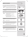
Safety Precautions
The following safety precautions must be taken when using your air conditioner.
WARNING
• Risk of electric shock can cause injury or death. • Disconnect all remote
electric power supplies before servicing, installing or cleaning.
• Installation must be done by the manufacturer or service agent or a
similar qualified person in order to avoid a hazard.
Installing the unit
The unit should not be installed by the user. Ask the dealer or
authorized company to install the units.
If the unit is installed improperly, water leakage, electric shock or fire
may result.
Mount with the lowest moving parts at least 2.5 m above the floor or
grade level. (If applicable)
The manufacturer does not assume responsibility for accidents or
injury caused by an incorrectly installed air conditioner. If you are
unsure about installation, contact an installation specialist.
When installing the built-in type air conditioner, keep all electrical
cables such as the power cable and the connection cord in pipe, ducts,
cable channels e.t.c to protect them against liquids, outside impacts
and so on.
The air conditioner should be used only for the applications for which
it has been designed: the indoor unit is not suitable to be installed in
areas used for laundry.
This appliance is not accessible to the general public. This appliance
should be installed according to the provided installation instruction.
When installing the air conditioner in a small room, the measure not to
exceed the dangerous density is needed.
- When refrigerant leaks and exceeds the dangerous density,
suffocation may occur.
If any gas or impurities except R410A refrigerant come into the
refrigerant pipe, serious problem may occur and it may cause injury.
Use only rated accessories and install the air conditioner with rated
equipments.
- If you dont’t use the rated accessories, the air conditioner may
drop from its place, water may leak or electric shock or fire may occur.
Ventilate your room when refrigerant gas leaks during installation.
- Toxic gas may generate when refrigerant gas contacts with heat.
Our units must be installed in compliance with the spaces indicated in
the installation manual to ensure either accessibility from both sides or
ability to perform routine maintenance and repairs. The units’
components must be accessible and that can be disassembled in
conditions of complete safety either for people or things.
For this reason, where it is not observed as indicated into the
Installation Manual, the cost necessary to reach and repair the unit (in
safety, as required by current regulations in force) with slings, trucks,
scaffolding or any other means of elevation won’t be considered
in-warranty and charged to end user.
E-3
AVXDU@@_IM_E_33764A-1_110621.indd 3
2011-06-23 오전 10:14:29
Safety Precautions (Continued)
Power supply line or circuit breaker
If the power cable of this air conditioner is damaged, it must be
replaced by service agent or similarly qualified persons in order to
avoid a hazard.
The unit must be plugged into an independent circuit if applicable or
connect the power cable to the auxiliary circuit breaker. An all pole
disconnection from the power supply must be incorporated in
the fixed wiring with a contact opening of >3mm.
The air conditioner must be installed in accordance with national
wiring regulations and safety regulations wherever applicable.
The electric work must be done by service agent or similarly qualified
persons according to national wiring regulations and use only rated
cable.
- If the capacity of the power cable is insufficient or electric work
is not properly completed, electric shock or fire may occur.
Install the cables with supplied cables firmly. Fix them securely so
that external force is not exerted to the terminal board.
- If the connection or fixing is incomplete, heat generation,
electric shock or fire may occur.
Connect the power cable between the indoor and outdoor unit
properly so that the electrical component box cover is not get loosen
and attach the cover securely.
- If the the cover is attached incompletely, heat generation,
electric shock or fire of the terminal board may occur.
E-4
AVXDU@@_IM_E_33764A-1_110621.indd 4
2011-06-23 오전 10:14:29
Make sure that you earth the cables.
- Do not connect the earth wire to the gas pipe, water pipe, lighting
rod or telephone wire. If earthing is not complete, electric shock or
fire may occur.
Install the circuit breaker.
- If the circuit breaker is not installed, electric shock or fire may occur.
Make sure that the condensed water dripping from the drain hose
runs out properly and safely.
Install the power cable and communication cable of the indoor and
outdoor unit at least 1m away from the electric appliance.
Install the indoor unit away from lighting apparatus using the ballast.
- If you use the wireless remote control, reception error may occur
due to the ballast of the lighting apparatus.
Do not install the air conditioner in following places.
- Place where there is mineral oil or arsenic acid.
Resin parts flame and the accessories may drop or water may leak.
The capacity of the heat exchanger may reduce or the air conditioner
may be out of order.
- The place where corrosive gas such as sulfurous acid gas generates
from the vent pipe or air outlet.
The copper pipe or connection pipe may corrode and refrigerant
may leak.
- The place where there is a machine that generates electromagnetic
waves.
The air conditioner may not operate normally due to control system.
- The place where there is a danger of existing combustible gas,
carbon fiber or flammable dust.
The place where thinner or gasoline is handled.
Gas may leak and it may cause fire.
E-5
AVXDU@@_IM_E_33764A-1_110621.indd 5
2011-06-23 오전 10:14:29
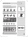
Accessories
The following accessories are supplied with the indoor unit.
The type and quantity may differ depending on the specifications.
User's
manual
Installation
manual
Pattern sheet
Insulation cover
pipe in
Insulation cover
pipe out
Insulation pipe(A)
Insulation pipe(B)
Cable tie
Flexible hose
Clamp hose
Washer
Rubber
Sleeve
E-6
AVXDU@@_IM_E_33764A-1_110621.indd 6
2011-06-23 오전 10:14:29
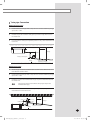
Selecting the Installation Location
Indoor Unit
There must be no obstacles near the air inlet and outlet.
Install the indoor unit on a ceiling that can support its weight.
Maintain sufficient clearance around the indoor unit.
Make sure that the water dripping from the drain hose runs away correctly and safely.
The indoor unit must be installed in this way, that they are out of public access. (Not touchable by the users)
After connecting a chamber, insulate the connection part between the indoor unit and the chamber
with t10 or thicker insulation. Otherwise, there can be air leak or dew from the connection part.
Rigid wall without vibration.
Where it is not exposed to direct sunshine.
Where the air filter can be removed and cleaned easily.
Space requirements for installation & service
Unit Depth(D)+50mm
Construction Standard for Inspection Hole.
1) In case, the ceiling is textile, Inspection hole dose not need.
2) In case, the ceiling is plaster board, Inspection hole depends on Inside height of the ceiling.
a. Height is more than 1m : Only “B” [Inspection for PBA] is applied.
b. Height is less than 1m : Both “A” & ”B” are applied.
c. “A” & ”B” are inspection holes.
20mm or more
Unit Width(W)
“A”=W+100mm
20mm or more
“B”=500mm
You must have 20mm or more space between the ceiling and the bottom of indoor unit. Otherwise, the noise from the vibration of
indoor unit may bother the user. When the ceiling is under construction, the hole for check-up must be made to take service, clean
and repair the unit.
It is possible to install the unit at an height of between 2.2~2.5m from the ground, if the unit has a duct with a well defined lenght
(300mm or more), to avoid fan motor blower contact.
D
Insulation Guide
B
Back
Front
A
Thickness: more than 10mm
Indoor unit
20.0~28.0kW
(1240x470x1040)
A
1240x1040
B
1240x1040
C
470x1040
C
D
Front/Back
470x1040
Insulate the front and back side
in proper size at the same time
when insulating the suction duct
and discharge duct.
Insulate the end of the pipe and some curved area by using separate insulator.
Insulate the discharge and suction part at the same time when you insulate connection duct.
E-7
AVXDU@@_IM_E_33764A-1_110621.indd 7
2011-06-23 오전 10:14:29
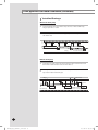
Selecting the Installation Location (Continued)
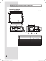
Drawing of the indoor unit
Unit : mm
34
29
385
100X2=200 93 22
209
236
660
647
598
OD 32
35
140X8=1120
1188 Air outlet duct flange
1240
470
1040
914 Suspension position
1306 Suspension position
1188 Air inlet duct flange
140X8=1120
Discharge side
Suction side
No.
Name
①
Liquid pipe connection
ø9.52 (3/8”)
Gas pipe connection
ND200/220 : ø19.05(3/4”)
ND280 : ø22.22(7/8”)
③
Drain pipe connection
VP25 (OD ø32, ID ø25)
④
Drain pipe connection (Option drain pump)
VP25 (OD ø32, ID ø25)
⑤
Power supply/Communication connection
⑥
Air discharge grille flange
⑦
Air suction flange
⑧
Hook
②
Description
3/8” or M10
E-8
AVXDU@@_IM_E_33764A-1_110621.indd 8
2011-06-23 오전 10:14:31
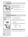
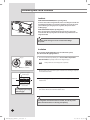
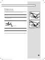
Indoor Unit Installation
It is recommended to install theY-joint before installing the indoor unit.
1 Place the pattern sheet on the ceiling at the spot where you want to install the
indoor unit.
Note
Since the diagram is made of paper, it may shrink or stretch slightly
due to temperature or humidity. For this reason, before drilling the
holes maintain the correct dimensions between the markings.
Concrete
2 Insert bolt anchors, use existing ceiling supports or construct a suitable support
as shown in figure.
3 Install the suspension bolts depending on the ceiling type.
Ensure that the ceiling is strong enough to support
the weight of the indoor unit.
Before hanging the unit, test the strength of each
attached suspension bolt.
If the length of suspension bolt is more than 1.5m,
it is required to prevent vibration.
If this is not possible, create an opening on the false
ceiling in order to be able to use it to perform the required
operations on the indoor unit.
Insert
Hole in anchor
Hole in plug
Suspension bolt( 3/8” or M10)
Ceiling support
4 Screw eight nuts to the suspension bolts making space for hanging the
indoor unit.
You must install the suspension bolts more than four when
installing the indoor unit.
5 Hang the indoor unit to the suspension bolts between two nuts.
Note
Piping must be laid and connected inside the ceiling when
suspending the unit. If the ceiling is already constructed, lay the
piping into position for connection to the unit before
placing the unit inside the ceiling.
Rubber
6 Screw the nuts to suspend the unit.
7 Adjust level of the unit by using measurement plate for all 4 sides.
Note
For proper drainage of condensate, give a 1° slant to the left or
right side of the unit which will be connected with the drain hose,
as shown in the figure. Make a tilt when you wish to install the
drain pump, too.
1°
Drain hose port
E-9
AVXDU@@_IM_E_33764A-1_110621.indd 9
2011-06-23 오전 10:14:31
Purging the Unit
Wet cloth
On delivery, the indoor unit is loaded with inert gas.
All this gas must therefore be purged before connecting the assembly piping.
To purge the inert gas, proceed as follows.
Unscrew the pinch pipe at the end of each refrigerant pipe.
Result: All inert gas escapes from the indoor unit.
Liquid
refrigerant port
Note
To prevent dirt or foreign objects from getting into the pipes
during installation, do NOT remove the pinch pipe completely until
you are ready to connect the piping.
Gas refrigerant port
Welding flame
Connecting the Refrigerant Pipe
There are two refrigerant pipes of differing diameters:
Refrigerant oil
A smaller one for the liquid refrigerant
A larger one for the gas refrigerant
The inside of copper pipe must be clean & has no dust.
The connection procedure for the refrigerant pipes varies according to the exit
position of the pipes from the indoor unit, as seen when facing the indoor in the “A”
side.
n port
Torque wrench
Spanner
Flare nut
Liquid refrigerant port
Gas refrigerant port
Drain hose port
Union
1
Remove the pinch pipe on the pipes and connect the assembly pipes to each
pipe, tightening the nuts, first manually and then with a torque wrench, a
spanner applying the following torque.
A
hange
Outer Diameter
6.35 mm (1/4")
9.52 mm (3/8")
12.70 mm (1/2")
15.88 mm (5/8")
Torque (kgf•cm)
145~175
333~407
505~615
630~769
Note
Must apply refrigerant oil on the flaring area to prevent a leak.
The designs and shape are subject to change
according to the model.
2
Be sure that there must be no crack or kink on the bended area.
E-10
AVXDU@@_IM_E_33764A-1_110621.indd 10
2011-06-23 오전 10:14:32
Cutting/Flaring the Pipes
1
Make sure that you prepared the required tools.
(pipe cutter, reamer, flaring tool and pipe holder)
2
If you want to shorten the pipe, cut it using a pipe cutter ensuring that the cut
edge remains at 90° with the side of the pipe. There are some
examples of correctly and incorrectly cut edges below.
Oblique
Rough
Burr
3
To prevent a gas leak, remove all burrs at the cut edge of the pipe using
a reamer.
4
Carry out flaring work using flaring tool as shown below.
A
Flaring tool
York
Die
Die
Clutch type
Wing nut type
Outer diameter
D(mm)
Flare tool for
R410A clutch type
6.35
9.52
12.70
15.88
Copper pipe
A(mm)
Conventional flare tool
Clutch type
Wing nut type
1.0~1.5
1.5~2.0
1.0~1.5
1.5~2.0
1.0~1.5
1.5~2.0
1.0~1.5
1.5~2.0
Check if you flared the pipe correctly. There are some examples of
incorrectly flared pipes below.
Correct
6
0~0.5
0~0.5
0~0.5
0~0.5
Flare nut
Inclined
Damaged Surface
Cracked
Uneven Thickness
Align the pipes and tighten the flare nuts first manually and then with a torque
wrench, applying the following torque.
6.35
145~175
8.70~9.10
9.52
333~407
12.80~13.20
12.70
505~615
16.20~16.60
15.88
630~769
19.30~19.70
Flare shape
(mm)
90° ±2°
Outer diameter
Connection
Flare dimension
(mm)
Torque(kgf•cm)
(mm)
45° ± 2°
5
Copper pipe
R 0.4~0.8
In case of needing brazing, you must work with Nitrogen gas blowing.
E-11
AVXDU@@_IM_E_33764A-1_110621.indd 11
2011-06-23 오전 10:14:32
Performing Leak Test & Insulation
Leak test
LEAK TEST WITH NITROGEN (before opening valves)
In order to detect basic refrigerant leaks, before recreating the vacuum and
recirculating the R410A, it’s responsible of installer to pressurize the whole
system with nitrogen (using a pressure regulator) at a pressure above
4.1MPa (gauge).
LEAK TEST WITH R410A (after opening valves)
Before opening valves, discharge all the nitrogen into the system and
create vacuum. After opening valves check leaks using a leak detector for
refrigerant R410A.
Leak check
Discharge all the nitrogen to create a vacuum and charge
the system.
Insulation
Once you have checked that there are no leaks in the system,
you can insulate the piping and hose.
No gap
1
To avoid condensation problems, place T13.0 or thicker Acrylonitrile
Butadien Rubber separately around each refrigerant pipe.
NoteAlways make the seam of pipes face upwards.
NBR(T13.0 or thicker)
2
Wind insulating tape around the pipes and drain hose avoiding to compress
the insulation too much.
3
Finish wrapping insulating tape around the rest of the pipes leading to the
outdoor unit.
4
The pipes and electrical cables connecting the indoor unit with the outdoor
unit must be fixed to the wall with suitable ducts.
Insulation cover pipe
Insulation pipe
Indoor unit
Be sure to overlap
the insulation
Must fit tightly against body
without any gap.
All refrigerant connection must be accessible, in order to permit
either unit maintenance or removing it completely.
E-12
AVXDU@@_IM_E_33764A-1_110621.indd 12
2011-06-23 오전 10:14:32
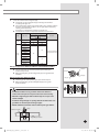
5
Select the insulation of the refrigerant pipe.
Insulate the gas side and liquid side pipe referring to the thickness
according to the pipe size.
Indoor temperature of 30°C and humidity of 85% is the standard condition.
If install in a high humidity condition, use one grade thicker insulator by
referring to the table below.
If installing in an unfavorable conditions,use thicker one.
Insulation’s heat-resistance temperature should be more than 120℃.
Pipe
Pipe size
Liquid
pipe
ø6.35~ø9.52
ø12.70~ø50.80
ø6.35
ø9.52
ø12.70
ø15.88
ø19.05
ø22.23
ø25.40
ø28.58
ø31.75
ø38.10
ø44.45
ø50.80
Gas
Pipe
Insulation Type(Heating/Cooling)
Standard
High humidity
[30°C, 85%]
[30°C, over85%]
EPDM, NBR
9t
9t
13t
13t
13t
19t
25t
19t
Remarks
Internal temperature
is higher than 120°C
32t
25t
38t
Refrigerant pipe before EEV kit and MCU or without EEV kit and MCU
You can contact the gas side and liquid side pipes but the pipes
should not be pressed.
When contacting the gas side and gas side pipe, use 1 grade thicker
Insulation
Insulation
insulation.
Refrigerant pipe after EEV kit and MCU
Liquid pipe
Gas pipe
Install the gas side and liquid side pipes, leave 10mm of space.
When contacting the gas side and liquid side pipe, use 1 grade
thicker insulation.
10mm
10mm
10mm
Install the insulation not to get wider and use the adhesives
on the connection part of it to prevent moisture from entering.
Gas pipe
Liquid pipe
Wind the refrigerant pipe with insulation tape if it is exposed to
outside sunlight.
Install the refrigerant pipe respecting that the insulation does not
get thinner on the bent part or hanger of pipe.
Add the additional insulation if the insulation plate gets thinner.
Hanger
Additional insulation
a
a×3
AVXDU@@_IM_E_33764A-1_110621.indd 13
Refrigerant pipe insulation
E-13
2011-06-23 오전 10:14:33
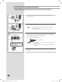
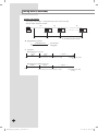
Drain pipe and Drain hose Installation
Care must be taken when installing the drain hose for the indoor unit to ensure that any condensate
water is correctly drained outside. The drain hose can be installed to the right or left side of the base pan.
1
Unscrew the 4 tapped screws to remove the cover of the drain hose
connection port.
2
Insert the flexible hose to the drain hose port.
Drain hose connection port
Note
Cable
Clamp
Indoor
Unit
3
Cable-tie
Clamp hose
Install the drain hose so that its length can be as short as possible.
Internal diameter of the drain hose should be the same or slightly bigger
than the external diameter of the drain hose port.
Insulation
Fix the flexible hose to the indoor unit with the supplied
cable clamp securely.
(Use the screwdriver to fix the flexible hose securely.)
Inner diameter of the drain hose
32mm(Inner diameter)
Flexible hose
Note
Must fit tightly against body
without any gap.
G
ive a slightly slant to the drain hose for proper drainage
of condensate.
F ix the flexible hose to the PVC with the supplied cable tie
securely.
No gap
4
Wrap the drain hose with the insulation drain as shown in figure and
secure it.
E-14
AVXDU@@_IM_E_33764A-1_110621.indd 14
2011-06-23 오전 10:14:33
Drain pipe Connection
Without the drain pump
1
Install horizontal drain pipe with a slope of 1/100 or more and fix it by hanger
space of 1.0~1.5m.
2
Install U-trap at the end of the drain pipe to prevent a nasty smell to reach
the indoor unit.
3
Do not install the drain pipe to upward position. It may cause water flow back
to the unit.
1~1.5m
Hanger
H≥50mm
1H
2
Drain pipe cleaning hole
Ceiling
Horizontal drain pipe
more than 1/100 slope
With the drain pump
1
The drain pipe should be installed within 330mm from the flexible hose and
then lift down 20mm or more.
2
Install horizontal drain pipe with a slope of 1/100 or more and fix it by hanger
space of 1.0~1.5m.
3
Install the air vent in the horizontal drain pipe to prevent water flow back to
the indoor unit.
Note
4
You may not need to install it if there were proper slope in the
horizontal drain pipe.
The flexible hose should not be installed upward position, it may cause
water flow back to the indoor unit.
Air vent
300mm or less
Flexible hose
1~1.5m
200mm or more
20mm or more
Hanger
Within 330mm
Ceiling
Horizontal drain pipe
more than 1/100 slope
E-15
AVXDU@@_IM_E_33764A-1_110621.indd 15
2011-06-23 오전 10:14:34
Drain pipe and Drain hose Installation (Continued)
Centralized Drainage
Without the drain pump
Install horizontal drain pipe with a slope of 1/100 or more and fix it by
hanger space of 1.0~1.5m.
2
Install U-trap at the end of the drain pipe to prevent a nasty smell to reach
the indoor unit.
100mm or more
1
Horizontal drain pipe
more than 1/100 slope
Ceiling
With the drain pump
1
Install main air vent at the front of the farthest indoor unit from the main
drain when installed indoor units are more than 3.
2
You may need to install individual air vent to prevent water flow back at the
top of each indoor unit drain pipe.
1~1.5m
Hanger
Individual
air vent
Main drain pipe
Main air vent
330mm or
less
Centralized horizontal drain pipe
(more than 1/100 slope)
E-16
AVXDU@@_IM_E_33764A-1_110621.indd 16
2011-06-23 오전 10:14:34
Testing the drainage
Prepare a little water about 2 liters.
1
Pour water into the drain pan in the indoor unit as shown in figure.
2
Confirm that the water flows out through the drain hose.
3
When the drain pump is installed, operate the unit as cooling mode and check a
drain pump pumping.
4
Drain pan
Check drain water drops at the end of the drain pipe.
Drain pipe
Drain water drops
5
Make sure there is no water leak at the drainage.
6
Reassemble the cover of water supply intake.
The designs and shape are subject to change
according to the model.
E-17
AVXDU@@_IM_E_33764A-1_110621.indd 17
2011-06-23 오전 10:14:35
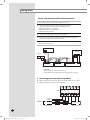
Wiring Work
Power and communication cable connection
1
Before wiring work, you must turn off all power source.
2
Indoor unit power should be supplied through the breaker
( ELCB or MCCB+ELB ) separated by the outdoor power.
ELCB: Earth Leakage Circuit Breaker
MCCB: Molded Case Circuit Breaker
ELB: Earth Leakage Breaker
3
The power cable should be used only copper wires.
4
Connect the power cable{1(L), 2(N)} among the units within maximum
length and communication cable(F1, F2) each.
5
Connect V1, V2(for DC12V) and F3, F4(for communication) when installing
the wired remote control.
Outdoor Unit
Wired Remote
Control
220-240V~
or
MCCB+
ELB
ELCB
Indoor Unit 1
Indoor Unit 2
Indoor Unit 3
h ELCB : Essential Installation
WARNING :
Power off before connecting any wires;
Indoor PBA will be damaged while V1,V2,F3,F4 short each other.
Connecting power for optional product
When installing optional product, make sure to follow below current capacity.
h Optional product is not supplied by manufacturer.
T/B
1(L)
2(N)
Vc
Vc
Vw
Vw
HOT
COIL
POWER : L
POWER : N
OPTION
VENTILATOR
AC, Below 2A
AC, Below 2A
E-18
AVXDU@@_IM_E_33764A-1_110621.indd 18
2011-06-23 오전 10:14:35
Selecting compressed ring terminal
Silver solder
B
D
d1
E
F
L
d2
t
Norminal
Norminal
Standard
Standard
Standard
Standard
dimensions for dimensions for
Allowance
Allowance
Allowance
Allowance
dimension
dimension
dimension
Min. Min. Max. dimension
Min.
cable (mm2)
screw (mm)
(mm)
(mm)
(mm)
(mm)
(mm)
(mm)
(mm)
(mm)
1.5
2.5
4
4
4
4
4
6.6
8
6.6
8.5
4
9.5
±0.2
3.4
±0.2
4.2
±0.2
5.6
+0.3
-0.2
+0.3
-0.2
+0.3
-0.2
1.7
±0.2
4.1
6
16
4.3
2.3
±0.2
6
6
17.5
4.3
3.4
±0.2
6
5
20
4.3
+0.2
0
+0.2
0
+0.2
0
0.7
0.8
0.9
Specification of electronic wire
Power supply
Max : 242V
Min : 198V
MCCB
XA
ELB or ELCB Power cable Earth cable
X A, 30mmA
0.1 sec
2
2.5mm2
2.5mm
Communication
cable
0.75~1.5mm2
Run transmission wiring between the indoor and outdoor units through a conduit to protect against external forces, and feed the conduit through the wall
together with refrigerant piping.
Rating current
Unit
Model
Rating current
200
3.3A
NDHH 220
3.8A
280
5.9A
Decide the capacity of ELCB(or MCCB+ELB) by below formula.
The capacity of ELCB(or MCCB+ELB) X[A] = 1.25 X 1.1 X ∑Ai
T X : The capacity of ELCB(or MCCB+ELB).
T ∑Ai : Sum of Rating currents of each indoor unit.
T Refer to each installation manual about the rating current of indoor unit.
Decide the power cable specification and maximum
length within 10% power drop among indoor units.
n
T coef: 1.55
∑(
Coef×35.6×Lk×ik
k=1
1000×Ak
)<
10% of input
voltage[V]
T Lk : Distance among each indoor unit[m]
Ak: Power cable specification[mm2]
ik : Running current of each unit[A]
E-19
AVXDU@@_IM_E_33764A-1_110621.indd 19
2011-06-23 오전 10:14:35
Wiring Work (Continued)
Example of Installation
- Total power cable length L = 100(m), Running current of each units 1[A]
- Total 10 indoor units were installed.
10[A]
9[A]
1[A]
ELCB
or MCCB+
ELB
Indoor unit1
0[m]
Indoor unit2
10[m]
Indoor unit10
20[m]
100[m]
Apply following equation.
n
Coef×35.6×Lk×ik
k=1
1000×Ak
∑(
)<
10% of input
voltage[V]
hCalculation
Installing with 1 sort wire
2.5[mm2]
-2.2[V]
220[V]
············ 2.5[mm2] ············
-2.0[V]
208.8[V](Within 198V~242V)
it's okay.
-(2.2+2.0+1.8+1.5+1.3+1.1+0.9+0.7+0.4+0.2)=-11.2[V]
Installing with 2 different sort wire
4.0[mm2]
220[V]
2.5[mm2]
-1.4[V]
4.0[mm2]
············ 2.5[mm2] ············
-1.2[V]
-(1.4+1.2+1.8+1.5+1.3+1.1+0.9+0.7+0.4+0.2)=-10.5[V]
209.5[V](Within 198V~242V)
it's okay.
E-20
AVXDU@@_IM_E_33764A-1_110621.indd 20
2011-06-23 오전 10:14:35
Select the power cable in accordance with relevant local and national
regulations.
Wire size must comply with local and national code.
For the power cable, use the grade of H07RN-F or H05RN-F materials.
You should connect the power cable into the power cable terminal
and fasten it with a clamp.
The unbalanced power must be maintained within 10% of supply
rating among whole indoor units.
If the power is unbalanced greatly, it may shorten the life of the
condenser. If the unbalanced power is exceeded over 10% of
supply rating, the indoor unit is protected, stopped and the error
mode indicates.
To protect the product from water and possible shock, you should
keep the power cable and the connection cord of the indoor and outdoor units in the iron pipe.
Connect the power cable to the auxiliary circuit breaker.
An all pole disconnection from the power supply must be incorporated
in the fixed wiring(≥3mm).
You must keep the cable in a protection tube.
Keep distances of 50mm or more between power cable and
communication cable.
Maximum length of power cables are decided within 10% of power
drop. If it exceeds, you must consider another power supplying
method.
The circuit breaker(ELCB or MCCB+ELB) should be considered more
capacity if many indoor units are connected from one breaker.
Use round pressure terminal for connections to the power terminal
block.
For wiring, use the designated power cable and connect it firmly,
then secure to prevent outside pressure being exerted on the
terminal board.
Use an appropriate screwdriver for tightening the terminal screws. A
screwdriver with a small head will strip the head and make
proper tightening impossible.
Over-tightening the terminal screws may break them.
See the table below for tightening torque for the terminal screws.
Tightening torque(kgf•cm)
M4
12.0~14.7
E-21
AVXDU@@_IM_E_33764A-1_110621.indd 21
2011-06-23 오전 10:14:35
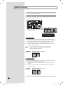
Indoor Unit Setting
1
Before installing the indoor unit, assign an address to the indoor unit according
to the air conditioning system plan.
2
The address of the indoor unit is assigned by adjusting MAIN(SW01, SW02) and
RMC(SW03, SW04) rotary switches.
SW01
SW02
SW03
SW04
The designs and shape are subject to change
according to the model.
SW05
SW06
SW07
Setting Main Address
The MAIN address is for communication between the indoor unit and the
outdoor unit. Therefore, you must set it to operate the air conditioner properly.
You can set the MAIN address from ‘00’ to ‘99’ by mixing SW01 and SW02.
The MAIN address from ‘00’ to ‘99’ should differ from each other.
Check the indoor unit address on the plan that you are to install and set the
address according to the plan.
Note
You may not need to set main address if you selected Auto
Address Setting from the outdoor unit: see details on the
outdoor unit installation manual.
For Example
When MAIN address is set as "12".
Setting RMC Address
The SW03 and SW04 RMC switch is the address setting switch for controlling
the indoor unit with the centralized controller.
You must set the SW03, SW04 and K2 switch when using the centralized
controller.
You don’t have to set the SW03 and SW04 RMC switch when not using the
centralized controller.
For Example
When RMC address is set as "12".
SW03
SW04
E-22
AVXDU@@_IM_E_33764A-1_110621.indd 22
2011-06-23 오전 10:14:36
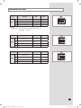
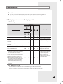
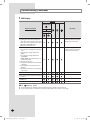
Additional Functions
No.
SW05
Function
ON
OFF
K1
External room sensor
Not use
Use
K2
Centralized controller
Not use
Use
K3
-
-
-
K4
Drain Pump
Not use
Use
K1 K2 K3 K4
g K1 OFF
Heating mode : Setting temperature compensation value = 0°C
Thermo OFF Fan OFF
No.
SW06
Function
ON
OFF
K5
Heating Current Temperature
Compensation
+2°C
+5°C
K6
Filter Time
1,000 hours
2,000 hours
K7
Hot Water Heater
Not Use
Use
K8
-
-
-
Function
ON
OFF
K9
Indoor Expansion Valve For
Heating Stop
Fix 160 step
0 or 160 step
K10
Wired Remocon Group Master
Not Use
Use
K11
External control
Not Use
Use
K12
Operation output
Thermal ON
Operation ON
No.
SW07
K5K6K7K8
K9K10K11K12
E-23
AVXDU@@_IM_E_33764A-1_110621.indd 23
2011-06-23 오전 10:14:36
Final Checks and User Tips
To complete the installation, perform the following checks and tests to ensure
that the air conditioner operates correctly.
1
Check the followings.
Strength of the installation site
Tightness of pipe connection to detect a gas leak
Electric wiring connections
Heat-resistant insulation of the pipe
Drainage
Earth conductor connection
Correct operation (follow the steps below)
After finishing the installation of the air conditioner, you should explain the
following to the user. Refer to appropriate pages in the User’s Manual.
1
How to start and stop the air conditioner
2
How to select the modes and functions
3
How to adjust the temperature and fan speed
4
How to adjust the airflow direction
5
How to set the timers
6
How to clean and replace the filters
Note
When you complete the installation successfully, hand over
the User’s Manual and this Installation Manual to the user for
storage in a handy and safe place.
E-24
AVXDU@@_IM_E_33764A-1_110621.indd 24
2011-06-23 오전 10:14:36
Troubleshooting
Detection of errors
If an error occurs during the operation, an LED flickers and the operation is stopped except the LED.
If you re-operate the air conditioner, it operates normally at first, then detect an error again.
LED Display on the receiver & display unit
LED Display
Indicators
Concealed Type
Abnormal conditions
Green
Operating
Red
Standard Type
Power reset
Error of temperature sensor in indoor unit
(OPEN/SHORT)
Displayed on appropriate
indoor unit which is operating
Error of heat exchanger sensor in indoor unit
Error of heat exchanger OUT sensor in
indoor unit
Error of outlet temperature sensor in
indoor unit
(OPEN/SHORT): For heat pump models only
Displayed on appropriate
indoor unit which is operating
Error of outdoor temperature sensor
Error of COND sensor
Error of DISCHARGE sensor
Displayed on appropriate
indoor unit which is operating
Displayed on outdoor unit
1. No communication for 2 minutes between
indoor unit and outdoor unit (communication error for more than 2 minutes)
1. Error of indoor unit:
Displayed on the indoor unit
regardless of operation
2. Indoor unit receiving the communication
error from outdoor unit
3. Outdoor unit tracking 3 minute error
2. Error of outdoor unit:
Displayed on the indoor unit
which is operating
4. When sending the communication error
from outdoor unit the mismatching of the
communication numbers and installed
numbers after completion of tracking.
(communication error for more than
2 minutes)
On
Flickering
Off
If you turn off the air conditioner when the LED is flickering, the LED is also turned off.
If you re-operate the air conditioner, it operates normally at first, then detect an error again.
E-25
AVXDU@@_IM_E_33764A-1_110621.indd 25
2011-06-23 오전 10:14:36
Troubleshooting (Continued)
LED Display
Indicators
Concealed Type
Abnormal conditions
Green
Operating
Red
Standard Type
S elf-diagnostic error
(including the indoor unit not detected)
1. Error of electronic expansion valve close
2. Error of electronic expansion valve open
3. Breakaway of EVA OUT sensor
4. Breakaway of EVA IN sensor
5. Breakaway of COND MID sensor
6. 2nd detection of refrigerant completely
leak
7. 2nd detection of high temperature
COND
8. 2nd detection of high temperature
DISCHARGE
9. COMP DOWN due to 2nd detection of
low pressure switch
10. Error of reverse phase
11. Compressor down due to 6th detection
of freezing
12. Self-diagnosis of condensation sensor
(G8, G9)
13. Compressor down due to condensation
ratio control
Displayed on appropriate
indoor unit which is operating
Displayed on outdoor unit
Displayed on appropriate
indoor unit which is operating
Displayed on outdoor unit
Error of float switch
Error of setting option switches for optional
accessories
EEPROM error
EEPROM option error
On
Flickering
Off
If you turn off the air conditioner when the LED is flickering, the LED is also turned off.
If you re-operate the air conditioner, it operates normally at first, then detect an error again.
E-26
AVXDU@@_IM_E_33764A-1_110621.indd 26
2011-06-23 오전 10:14:37
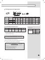
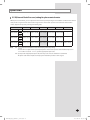
Option table
E.S.P(External Static Pressure)setting for phase control motor
With its phase control motor, you can adjust the indoor unit fan speed depending on the installation condition. If the external
static pressure is high so that the duct becomes longer or if the external static pressure is low so that the duct becomes
shorter, adjust the fan speed by referring the following table.
Static Pressure(mmAq)
Model
ND200HHXEA
ND220HHXEA
ND280HHXEA
Note
5
Step
HIGH
MID
LOW
HIGH
MID
LOW
HIGH
MID
LOW
10
15
20
25
28
Option code for indoor unit
015A17-150071 015A17-1500B4 015A17-1500D7 015A17-15023A 015A17-15028D
-
015A17-160097 015A17-1600C7 015A17-1600E8 015A17-16024D 015A17-16029F
-
015A17-170207 015A17-170229 015A17-17025B 015A17-17029E 015A17-1703D1 015A17-1703F3
represents E.S.P(External Static Pressure)range of factory setting.
You don’t have to adjust the fan speed separately if the external static pressure of the installation place is in
. When it is out of
, input the appropriate option code.
If you input the inappropriate option code,error may occur or the air conditioner is out of order.
The option code must be inputted correctly by the installation specialist or service agent.
E-27
AVXDU@@_IM_E_33764A-1_110621.indd 27
2011-06-23 오전 10:14:37
"EEE Yönetmeliğine Uygundur"
"This EEE is compliant with RoHS"
AVXDU@@_IM_E_33764A-1_110621.indd 28
2011-06-23 오전 10:14:37