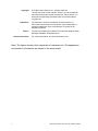
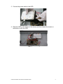
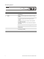
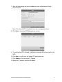
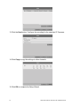
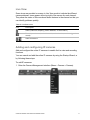
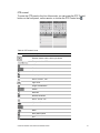
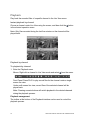
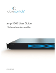
1
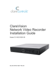
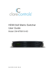
ClareVision
Network Video Recorder
Installation Guide
4-Channel NVR with PoE
Doc ID 2015-01-344 • Rev 04
Copyright
© 13JAN15 Clare Controls, Inc. All rights reserved.
This document may not be copied in whole or in part or otherwise
reproduced without prior written consent from Clare Controls, Inc.,
except where specifically permitted under US and international
copyright law.
Trademarks
The ClareVision name is a trademark of Clare Controls, Inc.
Other trade names used in this document may be trademarks or
registered trademarks of the manufacturers or vendors of the
respective products.
Version
Contact information
This document applies to CV-B4410-01 ClareVision Network Video
Recorder Installation Guide Revision 01.
For contact information, see www.clarecontrols.com.
Note: The figures shown in this manual are for reference only. The appearance
and interface of the device are subject to the actual model.
2
ClareVision Network Video Recorder Installation Guide
Content
NVR pre-installation...1 Package contents...1 NVR installation...1 Hard disk installation (optional)...2 Front panel...4 Rear panel...5 HDD storage calculation chart...6 Startup...7 Using the Setup Wizard...7 Live View...11 Adding and configuring IP cameras...11 Configuring basic parameters of IP cameras...12 PTZ control...14 PTZ settings...14 PTZ control...15 Playback...16 Instant playback by channel...16 Playback by channel...16 Backup...17 Understanding camera capacity in an NVR...19 Streaming video types...19 Adjusting settings...20 Specifications...21 Regulatory information...22 Contact information...23 ClareVision Network Video Recorder Installation Guide
i
ii
ClareVision Network Video Recorder Installation Guide
NVR pre-installation
This NVR is highly advanced surveillance equipment that should be installed with
care. Follow these precautionary steps before the installation of the NVR.
•
Keep all liquids away from the NVR.
•
Install the NVR in a well-ventilated and dust-free area.
•
Ensure environmental conditions meet factory specifications.
•
Install a manufacturer recommended HDD.
Package contents
1 X 4 channel NVR appliance
1 X AC power cord
1 X optical mouse
1 X remote Control
1 X SATA hard drive cable
4 X small Phillips head screws
1 X technical bulletin: NVR Understanding Camera Capacity
NVR installation
When installing the NVR:
•
Ensure there is ample room for the audio and video cables.
•
When routing cables, ensure that the bend radius of the cables is no less than
five times the diameter.
•
Connect both the alarm and RS-485 cable.
•
Ensure the NVR is grounded.
•
Environmental temperature should be within the range of 14ºF to 131ºF
(-10 ºC to 55 ºC).
•
Environmental humidity should be within the range of 10% to 90%.
ClareVision Network Video Recorder Installation Guide
1
Hard disk installation (optional)
Additional SATA hard disks can be installed on your NVR. Disconnect the power
from the NVR before installing a hard disk drive (HDD). A factory recommended
HDD should be used for this installation.
Tools required: screwdriver.
To install the hard disk drive into the NVR:
1. Remove the cover from the NVR by unfastening the screws on the rear and
side panels.
2. Connect one end of the data cable to the motherboard of the NVR and the
other end to the HDD.
2
ClareVision Network Video Recorder Installation Guide
3. Connect the power cable to the HDD.
4. Place the HDD on the bottom of the device, and then fasten the screws on
the bottom to affix the HDD.
ClareVision Network Video Recorder Installation Guide
3
Front panel
(1) (2) (3)
(4)
No.
Name
Description
1
Power
POWER: The POWER LED turns green when the NVR
is powered up.
2
Status
READY: The LED is green when the device is running
normally.
STATUS:
1. The light is green when the IR remote control is
enabled.
2. The light is red when the function of the composite
keys (SHIFT) are used.
3. The light will not be on if one of the above conditions
are not met.
ALARM: When an alarm occurs, the light will turn red.
HDD: The LED flashes red when the HDD is
reading/writing.
3
Tx/Rx
Tx/Rx LED flashes green when the network connection
is functioning normally.
4
USB
USB connector.
4
ClareVision Network Video Recorder Installation Guide
Rear panel
(1)
(2)
(3)
(4)
(5)
(6)
(7)
(8)
(9) (10)
(11)
No.
Item
Description
1
Network Interfaces with
PoE function
The network interfaces for the cameras and provide power
over Ethernet.
2
USB
Connects USB disks and devices.
3
HDMI
HDMI video output connector.
4
VGA
DB9 connector for VGA output. Display local video output
and menu.
5
AUDIO IN
BNC connector for audio input. (Also for two-way audio)
AUDIO OUT
BNC connector for audio output.
6
LAN Interface
1 network interface.
7
RS-485 Interface
Connector for RS-485 devices. T+ and T- pins connect to
R+ and R- pins of PTZ receiver respectively.
8
Ground
Ground (needs to be connected when NVR starts up).
9
Power Supply
12 VDC power supply.
10
Power Switch
Switch for turning on/off the device.
11
Fan
Removes heat from the device.
ClareVision Network Video Recorder Installation Guide
5
HDD storage calculation chart
The following chart shows an estimate of storage space used based on recording
on one channel for an hour at a fixed bit rate.
Table 1: Storage calculation chart
Bitrate
Storage used
96 K
42 M
128 K
56 M
160 K
70 M
192 K
84 M
224 K
98 M
256 K
112 M
320 K
140 M
384 K
168 M
448 K
196 M
512 K
225 M
640 K
281 M
768 K
337 M
896 K
393 M
1024 K
450 M
1280 K
562 M
1536 K
675 M
1792 K
787 M
2048 K
900 M
4096 K
1800 M
8192 K
3600 M
1638 4K
7200 M
Note: The values supplied for the storage space used are only for reference. The
storage values in the chart are estimated by formulas and may be different from
the actual value.
6
ClareVision Network Video Recorder Installation Guide
Startup
Proper startup procedures are crucial to expand the life of the NVR.
To start the NVR:
1. Check that the power supply is plugged in. We recommend that you use an
Uninterruptible Power Supply (UPS) in conjunction with the device.
2. Press the POWER button on the rear panel. The Power LED should turn
green as the unit starts.
Using the Setup Wizard
By default, the Setup Wizard starts once the NVR has loaded.
To operate the Setup Wizard:
1. Select the system language from the drop-down menu, and then click Apply
to save the resolution settings. The default language is English.
2. The Setup Wizard can walk you through settings of the NVR. If you do not
want to use the Setup Wizard, click Cancel. You can use the Setup Wizard
the next time by selecting the Start wizard when NVR starts? checkbox.
ClareVision Network Video Recorder Installation Guide
7
3. Click Next on the Wizard window to enter the Login window.
4. Enter the admin password. By default, the password is “secure7”
5. To change the admin password, select the New Admin Password checkbox.
Enter and confirm the new password in the given fields.
6. Click Next to enter the date and time settings window.
8
ClareVision Network Video Recorder Installation Guide
7. After the time settings are set, click Next to return to the Network Setup
Wizard window.
Note: The internal NIC IPv4 address must be on a separate subnet.
8. Click Next to enter the HDD Management window.
9. To initialize the HDD, click Init., initialization removes all the data saved in the
HDD.
10. Click Next. You will enter the Adding IP Camera interface.
11. Click Search to find the online IP Camera.
12. Select the IP camera, and then click Add.
ClareVision Network Video Recorder Installation Guide
9
13. Click the Next button. Configure the recording for the searched IP Cameras.
14. Click Copy to copy the settings to other channels.
15. Click OK to complete the Setup Wizard.
10
ClareVision Network Video Recorder Installation Guide
Live View
Some icons are provided on screen in Live View mode to indicate the different
camera statuses. Icons appear at the top right of the screen for each channel.
They show the status of the record and alarm features in the channel so that you
can identify problems quickly.
Table 2: Live View icons
Icon
Description
Alarm (video loss, tampering, motion detection, or sensor alarm)
Record (manual record, schedule record, motion detection, or alarm triggered
record)
Alarm and Record
Adding and configuring IP cameras
Add and configure the online IP cameras to enable the live view and recording
functions.
You can search and add the online IP cameras by using the Startup Wizard, or
by following these steps.
To add IP cameras:
1. Enter the Camera Management interface (Menu > Camera > Camera).
ClareVision Network Video Recorder Installation Guide
11
To add the online cameras with same network segment:
1. Click Search to search the online cameras.
2. Select the checkboxes for the cameras to be added.
3. Click Quick Add to add the cameras.
Configuring basic parameters of IP cameras
After adding the IP camera, the camera information displays on the page.
Configure the basic parameters of the IP camera.
To configure or edit IP cameras:
1. Click the icon to edit the parameters. You can edit the IP address, protocol,
and other parameters seen in the box below.
12
ClareVision Network Video Recorder Installation Guide
2. Click Apply to save the settings, and then click OK to exit the editing
interface.
More parameter options:
1. Scroll to the right on the screen, and then click the Advance Set icon.
2. You can edit the network information and the password of the camera.
3. Click Apply to save the settings, and then click OK to exit the interface.
Table 3: Basic icons
Icon
Description
Edit basic parameters of the camera
Delete the IP camera
Get the live view of the camera
ClareVision Network Video Recorder Installation Guide
13
PTZ control
Follow the procedure to set the parameters for the PTZ. You should configure the
PTZ parameters before you set the PTZ of the camera. Before you begin, ensure
the PTZ and the NVR are connected properly through the RS-485 interface.
PTZ settings
To set PTZ:
1. Enter the PTZ Settings interface (Menu > Camera > PTZ).
2. Choose the camera for PTZ setting next to the Camera label.
3. Enter the parameters for the PTZ camera.
Note: All the parameters should be the same as the PTZ camera parameters.
4. Click Copy to copy the settings from other PTZ cameras.
5. Click Apply to save and exit the interface.
14
ClareVision Network Video Recorder Installation Guide
PTZ control
To enter the PTZ panel in the Live View mode, you can press the PTZ Control
button on the front panel, on the remote, or choose the PTZ Control icon .
Table 4: PZT control icons
Icon
Description
Direction button and the auto-cycle button
The speed of the PTZ movement
3D-Zoom
Patrol
Previous item
Stop the patrol or pattern movement
Zoom+, Focus+, Iris+
Light on/off
Image Centralization
Pattern
Next item
Minimize windows
Zoom-, Focus-, IrisWiper on/off
Preset
Menu
Start pattern/patrol
Exit
ClareVision Network Video Recorder Installation Guide
15
Playback
Play back the recorded files of a specific channel in the Live View menu.
Instant playback by channel
Choose a channel under Live View using the mouse, and then click the
in the shortcut operation menu.
button
Note: Only files recorded during the last five minutes on the channel will be
played back.
Playback by channel
To playback by channel:
1. Enter the Playback menu.
Mouse: Right-click a channel in Live View mode and select
from the menu.
Front Panel: Press PLAY to play record files for the channel under a singlescreen live view.
Under multi-screen live view, record files of the selected channel will be
played back.
Note: Pressing numeric buttons will switch playback to the related channels
during the playback process.
Playback management
The toolbar at the bottom of the Playback interface can be used to control the
playback process.
16
ClareVision Network Video Recorder Installation Guide
Check the channel or channels if you want to switch playback to another channel
or execute simultaneous playback of multiple channels.
Backup
Recorded files can be backed up to various devices, such as USB flash drives,
USB HDDs, or a DVD writer.
To back up recorded files:
1. Enter Video Export interface (Menu > Export > Normal).
2. Select the channels you want to back up, set search condition, and then click
Search to enter the search result interface.
3. In the Search result interface, select the record files you want to back up and
click Export.
4. Enter the Export interface, choose a backup device, and then click Export to
start exporting.
ClareVision Network Video Recorder Installation Guide
17
Note: You can choose to export the record files and the related log files to the
player.
5. Check the backup results. Choose the record file in the Export interface, and
then press to check it.
18
ClareVision Network Video Recorder Installation Guide
Understanding camera capacity in an NVR
When setting up your NVR and cameras, you may notice that some of the
camera images may not display in Live View. This most often occurs when you
are displaying images in 1+5 mode, or 1+7 mode because the total bit rate for all
cameras is exceeding the NVR’s capacity. The actual capacity depends on the
total bit rate from all the cameras. However, it is good practice to allow some
headroom for machine operations, such as remote streaming.
NVR model
Capacity
4-channel
20 Mb
8-channel
40 Mb
16-channel
80 Mb
32-channel
160 Mb
64-channel
160 Mb
To fully understand NVR capacity, it is necessary to understand the concepts of
streaming video, resolution, quality, and bit rate. Streaming video is content sent
in compressed form over a network and processed in real time, that is, as it is
received.
Streaming video types
•
Main Stream: the high quality video that is being recorded and may be
streamed.
•
Sub Stream: never recorded; intended for streaming only. Default is
704 × 480, 584 Kbps at 8 fps.
•
Can be video alone, or video and audio compressed together. Audio requires
very little bandwidth.
The combination of the main stream and sub streams make up the total bit rate
of each camera. This is expressed in Kbps (kilobits per second) or Mbps
(megabits per second).
Bit rate is determined by the selected resolution (1280 × 720, 1920 × 1080,
2560 × 1920, etc.), frame rate (frames per second), and video quality (the
amount of compression being applied to each camera).
Example
32 channels of 720P cameras at 15 fps with good image quality will have
32 x (1536 + 512) = 65536 Kbps (about 66Mbps), so the 32-channel NVR can
support them.
ClareVision Network Video Recorder Installation Guide
19
Each channel can support a different camera, as long as they do not exceed the
total bit rate limit. It is entirely possible to mix 5 MP cameras with 4CIF IP
cameras, etc. Generally, 5 MP at 30 fps requires around 20 Mbps for best
quality. A 4-channel NVR is currently limited to 16 Mbps.
Adjusting settings
Be aware of your NVR’s capacity and make adjustments, if necessary. Adjust the
bit rate by lowering the resolution, frame rate, or video quality setting.
To adjust the setting:
1. Enter the Live View settings interface.
2. Adjust the Resolution, Frame Rate, and Video Quality settings.
20
ClareVision Network Video Recorder Installation Guide
Specifications
Video/audio
input
Network
Video/audio
output
Hard disk
External
interface
PoE
Others
IP video input
4-ch
Two-way audio input
1-ch, RCA (2.0 Vp-p, 1 kΩ)
Incoming bandwidth
20 Mbps
Output bandwidth
40 Mbps
Remote connection
128
Recording resolution
5 MP/ 3 MP/ 1080 p/ UXGA/ 720p/ VGA/
4 CIF/ DCIF/ 2 CIF/ CIF/ QCIF
HDMI/VGA output
1-ch, resolution:
1920 × 1080 P/ 60 Hz, 1600 × 1200/ 60 Hz,
1280 × 1024/ 60 Hz, 1280 × 720/ 60 Hz,
1024 × 768/ 60 Hz
CVBS (optional)
1-ch, BNC (1.0 Vp-p, 75 Ω)
Resolution: 704 × 576 (PAL); 704 × 480 (NTSC)
Audio output
1-ch, RCA (Linear, 1 kΩ)
Playback resolution
5 MP/ 3 MP/ 1080P/ UXGA/ 720 P/ VGA/
4 CIF/ DCIF/2 CIF/ CIF/ QCIF
Synchronous playback
4-ch, 720 P/ 2-ch, 1080P/ 1-ch, 5 MP
SATA
2 SATA interfaces for 2 HDDs
Capacity
Up to 4 TB for each disk
Network interface
1 RJ-45 10/ 100/ 1000 Mbps self-adaptive Ethernet
interface
Serial interface
1 RS-485 half-duplex interface
USB interface
2 × (USB 2.0)
Alarm in/out (optional)
4/ 1
Interface
4 independent 10/ 100 Mbps PoE Ethernet interfaces
Output Consumption
52 W
Supported Standard
AF
Power supply
100 to 240 VAC, 47 to 63 Hz, 3 A
Consumption
≤ 15 W (without hard disk)
Working temperature
14 to 131 ºF (-10 to +55ºC)
Working humidity
10 to 90%
Chassis
19 inch rack-mounted 1 U chassis
Dimensions
(W × D × H)
17.5 × 11.4 × 1.8 in (445 × 290 × 45 mm)
Weight
≤ 4.4 lb. (2 Kg) (without hard disk)
ClareVision Network Video Recorder Installation Guide
21
Regulatory information
DISCLAIMER
Underwriters Laboratories Inc. (UL) has not tested the performance or reliability
of the security or signaling aspects of this product. UL has only tested for fire,
shock or casualty hazards as outlined in UL’s Standard(s) for Safety, UL60950-1.
UL Certification does not cover the performance or reliability of the security or
signaling aspects of this product. UL MAKES NO REPRESENTATIONS,
WARRANTIES OR CERTIFICATIONS WHATSOEVER REGARDING THE
PERFORMANCE OR RELIABILITY OF ANY SECURITY OR SIGNALING
RELATED FUNCTIONS OF THIS PRODUCT.
FCC
This device complies with part 15 of the FCC Rules. Operation is subject to the
following two conditions: (1) This device may not cause harmful interference, and
(2) this device must accept any interference received, including interference that
may cause undesired operation.
This product and - if applicable - the supplied accessories too are marked with
"CE" and comply therefore with the applicable harmonized European standards
listed under the Low Voltage Directive 2006/95/EC, the EMC Directive
2004/108/EC, the RoHS Directive 2011/65/EU
2012/19/EU (WEEE directive): Products marked with this symbol cannot be
disposed of as unsorted municipal waste in the European Union. For proper
recycling, return this product to your local supplier upon the purchase of
equivalent new equipment, or dispose of it at designated collection points. For
more information see www.recyclethis.info.
2006/66/EC (battery directive): This product contains a battery that cannot be
disposed of as unsorted municipal waste in the European Union. See the product
documentation for specific battery information. The battery is marked with this
symbol, which may include lettering to indicate cadmium (Cd), lead (Pb), or
mercury (Hg). For proper recycling, return the battery to your supplier or to a
designated collection point. For more information see www.recyclethis.info.
22
ClareVision Network Video Recorder Installation Guide
Contact information
Clare Controls, Inc.
7519 Pennsylvania Ave, Suite 104
Sarasota, FL 34243
Support: 941.404.1072
Fax: 941.870.9646
http://support.clarecontrols.com
www.clarecontrols.com
ClareVision Network Video Recorder Installation Guide
23