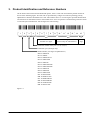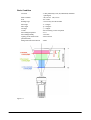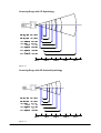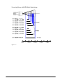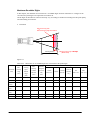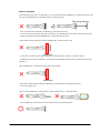
1
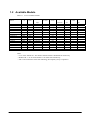
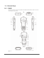
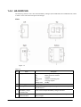
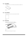
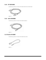
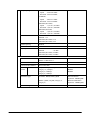
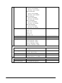
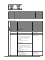
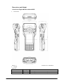
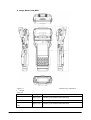
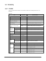
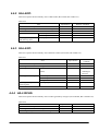
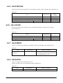
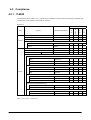
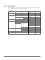
CASIO
IT-9000 Series
Hardware Manual
(Version 1.00)
CASIO Computer Co., Ltd.
Copyright © 2012. All rights reserved.
March 2012
Table of the Contents
Change History
Chapter 1.
Overview of the Products
1.1
Features at a Glance
1.2
Available Models
1.3
Options and Interfaces
1.4
External Views
1.4.1
IT-9000
1.4.2
HA-L60IO, HA-L62IO
1.4.3
HA-L30CHG, HA-L35CHG
1.4.4
HA-G32DCHG
1.4.5
HA-G20BAT
1.4.6
HA-C90PS5B
1.4.7
AD-S42120
1.4.8
DT-380USB
1.4.9
HA-L80USBH
1.4.10 HA-L81USBC
Chapter 2.
Hardware Specifications
2.1
IT-9000
2.2
HA-L60IO
2.3
HA-L62IO
2.4
HA-L30CHG
2.5
HA-G32DCHG
2.6
HA-L35CHG
2.7
HA-G20BAT
2.8
AD-S42120
Chapter 3.
Product Identification and Reference Numbers
Chapter 4.
Quality References
4.1
Environmental Performances
4.1.1
IT-9000
4.1.2
HA-L60IO
4.1.3
HA-L62IO
4.1.4
HA-L30CHG
4.1.5
HA-G32DCHG
4.1.6
HA-L35CHG
4.1.7
HA-G20BAT
4.1.8
AD-S42120
4.2
Electrical Performances
4.2.1
IT-9000
4.2.2
HA-L60IO
4.2.3
HA-L62IO
4.2.4
HA-L30CHG
4.2.5
HA-G32DCHG
4.2.6
HA-L35CHG
4.2.7
HA-G20BAT
4.2.8
AD-S42120
4.3
Mechanical Performances
2
4
5
5
7
9
10
10
12
14
15
16
16
16
17
17
17
18
18
32
34
36
37
38
39
40
41
42
42
42
43
44
44
45
45
46
47
48
48
48
49
49
50
50
51
51
52
4.3.1
4.3.2
4.3.3
4.3.4
4.3.5
4.3.6
4.3.7
4.3.8
4.4
4.4.1
4.4.2
4.4.3
4.4.4
4.4.5
4.4.6
4.4.7
4.4.8
4.5
4.5.1
4.5.2
4.5.3
4.5.4
4.5.5
4.5.6
4.5.7
4.5.8
4.6
4.6.1
4.6.2
4.6.3
IT-9000
HA-L60IO
HA-L62IO
HA-L30CHG
HA-G32DCHG
HA-L35CHG
HA-G20BAT
AD-S42120
Reliability
IT-9000
HA-L60IO
HA-L62IO
HA-L30CHG
HA-G32DCHG
HA-L35CHG
HA-G20BAT
AD-S42120
Compliance
IT-9000
HA-L60IO
HA-L62IO
HA-L30CHG
HA-G32DCHG
HA-L35CHG
HA-G20BAT
AD-S42120
Performance Reference
Scanning by C-MOS Imager
Handling Contactless Smart Card
Roll paper back barcode pre-print making guidelines
52
52
53
53
54
54
55
55
56
56
57
57
57
58
58
58
58
59
59
60
61
62
63
63
64
64
65
66
74
79
No part of this document may be produced or transmitted in any form or by any means, electronic or
mechanical, for any purpose, without the express written permission of CASIO Computer Co., Ltd. in
Tokyo Japan. Information in this document is subject to change without advance notice. CASIO Computer
Co., Ltd. makes no representations or warranties with respect to the contents or use of this manual and
specifically disclaims any express or implied warranties of merchantability or fitness for any particular
purpose.
© 2012CASIO Computer Co., Ltd. All rights reserved.
3
Change
History
Manual
Version no.
1.00
Date edited
March 2012
Page
All
Content
Original version
4
1. Overview of the Products
1.1 Features at a Glance
The IT-9000 series handheld terminal is designed using the new concept of the Human-centered Design
Process and is capable of performing various powerful functions including;
Outstanding Development Environment
• Microsoft® Windows Mobile® 6.5 English Version as the integrated OS
• Windows® Embedded CE 6.0 R3 English Version as the integrated OS
• Visual Studio 2005
• Visual Studio 2008
CPU, Memory
• High-performance CPU
Marvell® PXA320 Application Processor (runs at 624 MHz, maximum)
• Large-capacity memory
RAM
: 256 MB
F-ROM
: 256 MB
Capability of Scanning Industrial Standard Bar Code Symbologies
• 1D symbologies (with C-MOS Imager models. See Chapter 1.2.)
UPC-A, UPC-E, EAN8, EAN13, Codabar (NW-7), Code39, Interleaved 2of5 (ITF), MSI, Code11,
Code32, Code93, Code128 (GS1-128), IATA, GS1 DataBar Omnidirectional,
GS1 DataBar Limited, GS1 DataBar Expanded, GS1 DataBar Trancated
• 2D Stacked symbologies (with C-MOS Imager models. See Chapter 1.2.)
PDF417, Micro PDF, Code49, Composite, Codablock F, TLC39, GS1 DataBar Expanded Stacked, GS1
DataBar Stacked
• 2D Matrix symbologies (with C-MOS Imager models. See Chapter 1.2.)
Aztec, DataMatrix, Maxicode, QR Code, Micro QR, Chinese Sensible Code (HanXin Code)
Capturing Images
• Integrated digital camera (2.0 mega pixels, Autofocus)
5
Compatibility of Various Communication Options
• Integrated WWAN module compatible with GSM, GPRS, and EGPRS (EDGE)
• Integrated WLAN module compatible with IEEE802.11b/g standard
• Integrated GPS module
• Bluetooth® Version 2.0+EDR
• USB version 1.1 (Host/Client) for serial interface
Expandability
• microSD (SDHC) card slot
Improved Environment Durability
• Impact resistance
: 1.5 m in height*
• Dust/Water-splash proof : IP54 level (compliant with IEC60529 International Standard)
* ; The drop durability height is a measured value resulting from actual testing. It does not necessarily guarantee the
product from damage.
6
1.2 Available Models
Table 1.1 List of available models
Model No.
OS
Printer
C-MOS
Imager
W-WAN
W-LAN
Magnetic
SAM
Card Reader
Slot
Camera
2ndSD
Slot
IT-9000-E
IT-9000-GE
IT-9000-GMC30E
IT-9000-20E
CE
CE
CE
CE
80mm
80mm
82.55mm
80mm
Laser Aimer
Laser Aimer
Yes
Yes
-
11bg
11bg
11bg
11bg
Yes
-
3
2
2
3
Yes-
-
IT-9000-G20E
CE
80mm
Laser Aimer
Yes
11bg
-
2
-
-
IT-9000-GM30E
IT-9000-05E
IT-9000-05E-CN
IT-9000-G05E
IT-9000-GMC25E
IT-9000-25E
IT-9000-G25E
IT-9000-GC25E
IT-9000-GM35E
IT-9000-MC25E*
IT-9000-C25E*
CE
Mobile
Mobile
Mobile
Mobile
Mobile
Mobile
Mobile
Mobile
Mobile
Mobile
82.55mm
80mm
80mm
80mm
80mm
80mm
80mm
80mm
82.55mm
80mm
80mm
LED Aimer
LED Aimer
Laser Aimer
Laser Aimer
Laser Aimer
LED Aimer
Laser Aimer
Laser Aimer
YesYes
Yes
Yes
Yes
Yes
-
11bg
11bg
11bg
11bg
11bg
11bg
11bg
11bg
11bg
-
Yes×
Yes
Yes
Yes
-
2
3
1
2
2
3
2
2
2
3
3
Yes
Yes
Yes
Yes
YesYes
Notes
- “-CN” in the “Model no.” box denotes that the model is dedicated for China only.
- Model with “*” at its model number is for USA and Canada only.
- NFC is the contactless smart card technology developed by Sony Corporation.
7
Table 1.2 List of options
Option
Product
Cradle
USB Cradle
Ethernet Cradle
Battery
Battery charger
Battery Pack
Dual Battery Charger
Cradle-type Battery Charger
Car Mounted-type Battery
Charger
AC adaptor
(for HA-L60IO, HA-L62IO, HA-G32DCHG)
Model no.
HA-L60IO
HA-L60IO-CN
HA-L62IO
HA-L62IO-CN
HA-G20BAT
HA-G20BAT-CN
HA-G32DCHG
HA-G32DCHG-CN
HA-L30CHG
HA-L30CHG-CN
HA-L35CHG
HA-L35CHG-CN
AD-S42120B-N
AD-S42120C-N5
Power Cable
(for AD-S42120)
USB cable
Cable
Others
Screen Protect Sheet
AD-S42120BE-CN
AC-CORD-EU
AC-CORD-US
AC-CORD-TW
AC-CORD-KR
AC-CORD-AU
DT-380USB
DT-380USB-CN
HA-L80USBH
HA-L80USBH-CN
HA-L81USBC
HA-L81USBC-CN
HA-C90PS5B
Remark
for China
for China
for China
for China
for China
for China
without power cable accompanied
for global without Europe
without power cable accompanied
for Europe
for China
for Europe
for USA/Canada
for Taiwan
for Korea
for Australia/New Zealand
for cradle – PC
For Host
For Client
Note:
“-CN” in the “Model no.” box denotes that the model is dedicated for China only.
8
1.3 Options and Interfaces
IT-9000
802.11bg
Products
Access
Point
IEEE802.11bg
Module
Mobile
Phone
GSM/W CDMA
GPS
Bluetooth
Products
Satellites
Head Set
Bluetooth Module
(Ver2.0+EDR)
USB
H t
Extension Port
Cradle-type
Battery Charger
HA-L30CHG
Car Mounted-type
Battery Charger
HA-L35CHG
DC Jack
PC
AC Adapter
AD-
LAN
P t
PC
USB
H t
USB Product
USB Client
PC
AC Adapter
AD-
AC Adapter
ADCar Adapter
AC Adapter
AD-
SD Card Slot
SD Card
SIM/SAM Card Slot
SIM/SAM Card
SIM/SAM Card Slot
SIM/SAM Card
SIM/SAM Card Slot
SIM/SAM Card
Battery Terminal
USB Products
USB Client
USB Cradle
HA-L60IO
Ethernet
Cradle
Power Supply
IT9000
PC
ISO 14443
Type A,B,Felica
NFC
USB Terminals
(Host/Client)
Mobile Printer
Battry Pack
HA-G20BAT
AC Adapter
AD-S42120C
Figure 1.1
9
Battry Pack
HA-G20BAT
Battry Pack
HA-G20BAT
Battry Pack
HA-G20BAT
Battry Pack
HA-G20BAT
Battry Pack
HA-G20BAT
Battry Pack
HA-G20BAT
Dual Battery Charger
Dual Battery Charger
Dual Battery Charger
HA-G32DCHG
HA-G32DCHG
HA-G32DCHG
1.4 External Views
1.4.1 IT-9000
The following external views show all models of IT-9000 series PDA. Refer to Table 1.3 for each
referenced part on the terminal.
Figure 1.2
10
Table 1.3
No.
Name
1
Printer
2
Splash Protect Cover
3
Power Key
4
Indicator 2
5
Indicator 1
Description
Printed roll paper is torn off here.
The splash protect cover. Open the cover when printing.
Turns on and off the power.
Flashes in blue when operating via Bluetooth or in orange when operating
via WLAN, WWAN or GPS. Lights in green when reading a bar code
successfully or in red when alarming (programmable).
Orange
: Charging battery pack.
Green
Red
: Charging battery pack is complete.
: Battery pack is abnormal or the surrounding temperature is out
of the charging temperature range.
Buzzer and voice messages are output.
Displays text and operating instruction. Also used to operate the terminal and
enter data using stylus provided.
6
7
Speaker
Touch Screen
8
Stroke key
9
10
11
Magnetic Card Reader
Printer Cover Lock
Switch
R-side key
12
L-side key
13
14
SD card slot
DC Jack
15
16
USB Port
Barcode reader
This key can be assigned to any function available. In the imager model, use
it to scan bar codes.
This key can be assigned to any function available. In the imager model, use
it to scan bar codes.
Slot for inserting SD memory card.
The dedicated AC Adaptor is connected to this jack when charging the
lithium-ion battery pack.
For connecting to a USB products.
Reads 1D and 2D symbologies.
17
18
NFC Reader
Reset Switch
Used to reset the terminal.
19
20
Hand Strap Hook
Cradle Mount Holes
Hook the hand strap here.
Used to mount the terminal in cradle.
21
Extension Port
Provided for connecting an external device.
22
Power Supply/Data
Communication
terminals
Battery Pack Cover
Lock Switch
Battery Pack Cover
Neck Strap Hooks
SIM/SAM Card slot
LED Light (Flash)
Digital Camera
Used for USB communication or to supply power to the terminal and to
charge the battery pack via either Cradle or Cradle-type Battery Charger.
23
24
25
26
27
28
There are a total of 24 keys including function keys , numeric keys and cursor
Key. Each numeral or symbol on the key tops is backlit.
Magnetic cards are read by passing through this magnetic card reader.
Lock the Printer Cover.
Used to lock the battery cover and to release it.
Used to cover the battery compartment that holds the battery pack inside.
Hook the neck strap here.
Slot for inserting SIM/SAM card.
Used to light up an object when capturing it with the digital camera.
Used to capture photographs, images.
11
1.4.2 HA-L60IO, HA-L62IO
The following external views show the USB Cradles (HA-L60IO, HA-L60IO-CN) and Ethernet Cradle
(HA-L62IO, HA-L62IO-CN). Refer to Table 1.4 for each referenced part on the cradles.
Views
Figure 1.3
12
Table 1.4
No.
Name
1
Terminal Detect Switch
2
3
4
5
Mount Hooks
Removal Button
Power Supply/Data
Communication terminal
Power LED
6
7
Power Switch
USB Client Port
8
9
USB Host Port
LAN Port
(for HA-L62IO)
LAN Connection Status
LED
(for HA-L62IO)
10
11
LAN Communication
Status LED
(for HA-L62IO)
12
Selector Switch
13
AC Adaptor Jack
Description
This switch detects when the terminal is mounted correctly on the
cradle.
Used to hook the terminal in the cradle.
Used to remove the terminal in the cradle.
These contacts are used for communication and supplying power to
the terminal.
This LED indicates the power status and the mounting status of the
terminal in the cradle.
Off
: The terminal is not mounted. Or, the AC adaptor is
not connected.
On in Green : Power is turned on, and the terminal is correctly set
in the cradle.
Turns on and off the power.
This port is used to transmit data (download or upload) by
connecting the Cradle to a PC using USB cable (DT-380USB). The
dedicated driver must be installed in the PC before connecting the
Cradle to the PC.
This port is used to connect a USB peripheral device.
This port is used for connecting the cradle to PC or hub via LAN
cable so that data can be transmitted (uploaded or downloaded).
This LED shows the LAN connection status.
Off
: LAN cable not connected correctly.
On in Green : LAN cable connected correctly.
This LED shows the LAN operation status.
Off
: No communication.
On in Green : Communication in progress.
This switch is used to switch between the USB host port and USB
client port.
Connect the dedicated AC adaptor, AD-S42120, here.
13
1.4.3 HA-L30CHG, HA-L35CHG
The following external views show the Cradle-type Battery Chargers (HA-L30CHG, HA-L30CHG-CN) and
Car Mounted Cradle-type Battery Chargers (HA-L35CHG, HA-L35CHG-CN). Refer to Table 1.5 for each
referenced part on the charger.
Views
Figure 1.4
Table 1.5
No.
Name
1 Terminal Detect
Switch
2 Mount Hooks
3 Removal Button
4 Power Terminals
5
6
7
8
Description
This switch detects when the terminal is mounted correctly on the
Battery Chager .
Used to hook the terminal in the Battery Charger.
Used to remove the terminal in the Battery Charger.
Power is supplied to the terminal via these contacts.
Power LED
This LED indicates the power status and the mounting status of the terminal.
Power Switch
AC Adaptor Jack
Car plug code Jack
Off
: The terminal is not mounted.
On in green : Power is turned on and the terminal is mounted correctly.
Turns on and off the power.
Connect the dedicated AC adaptor, AD-S42120, here.
Connect the dedicated Car plug code , here.
14
1.4.4 HA-G32DCHG
The following external views show the Dual Battery Chargers (HA-G32DCHG, HA-G32DCHG-CN). Refer
to Table 1.6 for each referenced part on the charger.
Views
Figure 1.5
Table 1.6
No.
Name
1 Charge Indicator LED
2
3
Power Supply Terminal
AC Adaptor Jack
4
Dual Battery Charger
Connection Port
Connection Bracket
Attachment Holes
5
Description
This LED indicates the charge status of battery pack(s).
Off
: Battery pack is not mounted.
Red
: Charging.
Flashing Red
: Problem on the battery pack.
Green
: Charging complete.
Flashing Green : Standby.
Power is supplied to the terminal via these contacts.
This is used to supply power by connecting the dedicated AC adaptor,
AD-S42120, here.
Used to connect multiple Dual Battery Chargers each other.
The connection bracket attaches here when you connect multiple Dual
Battery Chargers.
15
1.4.5 HA-G20BAT
The following external view shows the Battery Packs (HA-G20BAT, HA-G20BAT-CN).
Figure 1.7
1.4.6 HA-C90PS5B
The following external view the Screen Protect Sheet (HA-C90PS5B).
Figure 1.9
1.4.7 AD-S42120
The following external view shows the AC Adaptors
(AD-S42120C-N5,AD-S42120B-N,AD-S42120BE-CN).
Figure 1.11
Note:
Power cable does not accompany to the AC Adaptor.
16
1.4.8 DT-380USB
The following external view shows the USB cable between cradle and PC.
Figure 1.5
1.4.9 HA-L80USBH
The following external view shows the USB cable (Host).
Figure 1.6
1.4.10 HA-L81USBC
The following external view shows the USB cable (Client).
Figure 1.7
17
2. Hardware Specifications
2.1 IT-9000
Tables 2.1 and 2.2 explain about the hardware specifications of all models of IT-9000 series including the
models with “-CN” denotation.
Table 2.1
Item
CPU, Memory
CPU
RAM
FROM
OS
Specification
Marvell® Xscale Processor PXA320 runs at
624 MHz
256MB
256 MB (user area;
CE:approx. 176MB
Mobile:approx. 130MB
®
Microsoft Windows EmbeddedCE® 6.0R3
English Version
Microsoft® Windows Mobile® 6.5 English
Version
Classic (without W-WAN model)
Professional (with W-WAN model)
Continue.
18
Remark
C-MOS Imager
Method
Aimer method
Laser emit angle
Resolution
PCS
Focal distance
Daylight for scanning
Readable 1D
symbologies
Readable Stacked 2D
symbologies
Readable Matrix 2D
symbologies
Vibrator
Display
Display device
No. of dots
Dot pitch
Gradation
Display font
Backlight
Viewing angle
Touch Panel
Hardness
Indicator
LED
C-MOS Imager, 752 x 480 (Wide VGA),
monochrome
Laser 650+10nm or -5nm <1 mW
Redirected downward at 0 degree
1D
: 0.15mm
Stacked 2D : 0.169mm
Matrix 2D
: 0.25mm
0.45 (minimum)
4.5 inches (11.43 cm)
50,000 Lux or less
UPC-A, UPC-E, EAN8, EAN13, Codabar
(NW-7), Interleaved 2of5 (ITF), MSI, Code11,
Code32, Code39, Code93, Code128 (GS1-128),
IATA, GS1 DataBar Omnidirectional, GS1
DataBar Truncated, GS1 DataBar Limited, GS1
DataBar Expanded
PDF417, Micro PDF, Code49, Composite,
Codablock F, TLC39, GS1 DataBar Expanded
Stacked, GS1 DataBar Stacked
Azteck, DataMatrix, Maxicode, QR Code, Micro
QR
Notification of scanning bar code
TFT
480 (horizontal) x 640 (vertical) VGA
0.117 (horizontal) x 0.117 (vertical) mm
65,536 colors
Scalable font
LED backlight
35 degree (Left, Right), 10 degree (Up),
50 degree (Down)
Resistive expression analog touch panel
Pencil hardness 2H over
Blanview® by OrutusTtech
See “Dead Pixels”.
Contrast 10 over
plastic
Indicator 1; status of charging battery pack,
Indicator 2; status of communication
Dead Pixels
The LCD panel employed in this product uses high precision and substantial number of components which
commonly cause a small number of the pixels not to light or to remain lit all the time. This is due to the
characteristics of LCD panel yield in accuracy over 99.99% and permissible.
Continue.
19
Input
Keyboard
Control keys
Side keys
WLAN
Standard
Module no.
Radio type
Emission Designation
Spectrum Spread
modulation
Modulation type
Frequency range
Power key, Reset switch
L-Side,/R-Side key
IEEE 802.11b/g
WM-G-MR-09-REF2
Spread Spectrum
IEEE801.11b : D1D, G1D
IEEE802.11g : G1D
Channel spacing
IEEE802.11 b : DSSS
IEEE802.11 g : OFDM
BPSK, QPSK, CCK, 16QAM, 64QAM
IEEE802.11b : 2,400 to 2,483.5 MHz
IEEE802.11g : 2,400 to 2,483.5 MHz
IEEE802.11b : 11 Mbps (maximum)
IEEE802.11g : 54 Mbps (maximum)
IEEE802.11b/g : 50 m (indoor) to 150 m
(outdoor)
11b : 13
11g : 13
5MHz
Channel band width
22MHz
Output power
IEEE802.11b : 13.5dBm (minimum)
17.5dBm (maximum)
IEEE802.11g : 12.5dBm (minimum)
16.5dBm (maximum)
Roaming among Access-Points
Security
: WEP (64/128bit),
WPA, WPA2
WPA encrypted
: TKIP, AES
method
Authorize method
: PSK, EAP-TLS,
PEAP-MSCHAP-V2
Baud rate
Communication range
Number of channels
Other feature
Security
Continue.
20
By USI
ITU
Vary depending on the
environment condition
Printer
Method
Paper width
Printing width
Dropin-type Thermal line dot
80 mm or 58 mm
The width of paper must be
preset with software prior to
use of the printer. In order to
use 58mm paper, “58mm
Width Adjuster” must be
installed first.
Paper thickness
72 mm (for an 80 mm/82.55mm paper)
48 mm (for a 58 mm paper)
55μ∼110μ
Speed
28 lines per second (Max.)
See note 1.
Paper
Roll paper, label paper
Use only CASIO
recommended papers.
Font size
“x1”, “x1.5”, “x2”, “x3”, and “x4” sizes are
supported.
ANK/Symbologies (UPC-E, NW-7, Code39,
ITF, Code128, OCR-B, user-defined characters x
128)
In white, black and reverse modes. Mixture of
different font sizes.
Print position aline
Backside barcode read
0.125mm(8dot/mm)
Font types
Print function
Sensor
Dot pitch
Dot size
0.22mm (Length) ×0.125mm(Width)
1dot line
0.125mm
SAM
Standard
ISO7816 IC Card standard
General specification
3V, 1.8V SIM card supported
MCR
F2F FormatISO7811-2、ISO7811-6)
Application card
The number of the
3Tracks(ISO7811-2、ISO7811-6)
simultaneous uptake
trucks
Magnetic data reading side One side
Card run direction
Both direction
100∼1500mm/sec
Card slide speed
Continue.
21
-
-
Bluetooth Class 2
Standard
Module no.
Radio type
Modulation
Modulation type
Emission Designation
Frequency range
Communication range
Number of channels
Channel spacing
Channel band width
Output power
GSM
Standard
Module no.
Features
Data
Packet
transfer
Bluetooth® specification Ver.2.0+EDR
LBMA46LCS3-332
Spread Spectrum
Frequency Hopping (“FHSS”)
GFSK (1Mbps), Π/4-dqpsk (2Mbps), 8-DPSK
(3Mbps)
F1D, G1D
2,400 to 2,483.5 MHz
Approx. 3 m
79
1 MHz
1 MHz
Max. 4 dBm (PowerClass 2)
3GPP release 99
MC8795V
Voice, Packet data
GPRS: Multi Slot Class 12
Mobile Station Class B
Coding Scheme CS1-4
EGPRS(EDGE):
Multi Slot Class 12
Mobile Station Class B
Coding Scheme MCS1-9
Modulation type
GSMK/8-PSK (EGPRS(EDGE)
Emission Designation
GPRS
: 252KGXW
EGPRS(EDGE) : 248KG7W
Continue.
22
- By Murata Manufacturing
Co., Ltd.
-
ITU
- Vary depending on the
environment conditions
-
- By Sierra Wireless
-
- ITU
Frequency range
No. of Channels
Channel spacing
Channel band width
Output power
W-CDMA
Standard
GSM850
Uplink : 824 to 849 MHz
Downlink : 869 to 894 MHz
E-GSM900
Uplink : 880 to 915 MHz
Downlink : 925 to 960 MHz
GSM1800 (DCS1800)
Uplink : 1,710 to 1,785 MHz
Downlink : 1,805 to 1,880 MHz
GSM1900 (PCS1900)
Uplink : 1,850 to 1,910 MHz
Downlink : 1,930 to 1,990 MHz
GSM850 : 124
GSM900 : 174
GSM1800 (DCS1800) : 374
GSM1900 (DCS1900) : 299
200 KHz
200 KHz
GSM850
: 32 dBm
GSM900
: 32 dBm
GSM1800 (DCS1800) : 29 dBm
GSM1900 (DCS1900) : 29 dBm
Module no.
Communication features
Data
Packet
transfer
UMTS/W-CDMA : 3GPP release 99
HSDPA : 3GPP release 5
MC8795V
Voice, Packet data
64Kbps, 128Kbps, 384Kbps
Category 12 (1.8Mbps)
Category 6 (3.6Mbps)
Category 8 (7.2Mbps)
Modulation type
W-CDMA : BPSK, HPSK, QPSK
Emission Designation
Continue.
- Sierra Wireless
HSDPA
HSDPA
HSDPA
HSDPA : QPSK, 16QAM (Category 6,
Category 8)
Data Modulation
Up/Down : BPSK/QPSK
Diffusion Modulation
Up/Down : HPSK/QPSK
4M21F9W
ITU
23
Frequency range
No. of Channels
Channel spacing
Channel band width
Output power
GPS
General specification
Positioning system
Protocol
Sensitivity
SIM
Standard
General specification
Continue.
Band I UMTS2100
Uplink : 1920 1980MHz
Downlink : 2110 2170MHz
Band II UMTS1900
Uplink : 1850 1910MHz
Downlink : 1930 1990MHz
Band V UMTS850
Uplink : 824 849MHz
Downlink : 869 894MHz
Band VI UMTS800
Uplink : 830 840MHz
Downlink : 875 885MHz
Band VIII UMTS900
Uplink : 880 915MHz
Downlink : 925 960MHz
Band I : 299
Band II : 299
Band V : 124
Band VI : 49
Band VIII : 174
200 KHz
5MHz
Band I UMTS2000 : 23dBm
Band II UMTS900 : 23dBm
Band V UMTS850 : 23dBm
Band VI : UMTS800 : 23dBm
Band VIII : UMTS900 : 23dBm
12 channels and receiver / L1 1575.42 MHz,
C /A code
Standalone – GPS (S-GPS)
Assisted – GPS (A-GPS)
NMEA-0183
Acquisition sensitivity: -145 dBm
Tracking sensitivity : -158 dBm
ISO7816 IC Card standard
3V, 1.8V SIM card supported
24
NFC
Carrier frequency
Antenna
Field work
Bit rate
Modulation
Modulation rate
Read range
Read area
Communication
protocol
13.56MHz±7kHz
Magnetic loop antenna
Magnetic field strength (at contact with case)
output 1.5A/m over
Magnetic field strength (at 50mm distance from
case) output 0.15A/m over
ISO14443 Type A : 106kbps
ISO14443 Type B : 106kbps
FeliCa : 212kbps, 424kbps
ISO15693 : 1.65kbps
ASK
10%, 100% modulation
ISO14443 Type A/B, FeliCa : 0mm (Contact with
case)
ISO15693 : 0mm (Contact with case) to 60mm
(max)*
*Reference value because different with tag
antenna design
30mm x 60mm
Standard:
ISO14443 Type A
(MIFARE Standard /MIFARE Ultralight)
ISO14443 Type B
(JICSAP)
Compliant with
ISO10373-6
Compliant with
ISO10373-7
Dependent on smart card
It is recommended to use
smart card that is compliant
with the ISO standard.
FeliCa® (JIS X6319)
(FeliCa Standard)
SD slot
micro SD
USB
Host
ISO15693
(I.CODE SLI/I.CODE S LI-S/I.CODE
SLI-L/my-d VID plain/my-d Light/Tag-it
plus* /Tag-it pro/Tag-it standard)
* There is some not support command.
Compatible with SDHC/SDIO.
Compatible with SDHC.
Baud rate
Power to
external
device
Client
Baud rate
Power/Signal terminals
Pin layout
Continue to page 26.
Full speed (12 Mbps)
Low speed (1.5 Mbps)
5V/500mA
Full speed (12 Mbps)
See Table 2.2.
25
It takes time for write Tag-it
data. There is command
which is needed retry
operation in application.
Table 2.2
Pin no.
1
2
3
4
5
6
Signal
GND
DD+
V BUS
USB_ID
V CRADLE
Continued from page 25.
Camera
Number of pixels
Device
F value (Aperture)
Focal distance
Image capture range
LED light
Speaker
Microphone
Power
Operating power
Memory backup
Operating period
Description
GND
USB DUSB D+
Power from USB cradle
Switch-over between USB host and USB client
Power supply/Charge to the terminal
Direction
IN/OUT
IN/OUT
OUT IN/OUT
IN
-
Approximately 2,000,000 pixels
1/4.0-type color CMOS
2.8±5%
f = 3.45 mm (Autofocus)
10 cm to infinite
21,000 mcd
Warning sound, etc.
Voice sound input
- 1,600 x 1,200 pixels
Lithium-ion battery pack
-
Lithium battery (rechargeable)
Approx 20hours
HA-D20BAT
HA-D21LBAT
Integrated
At room temperature
New battery pack
Above time periods are based on the ratio of
cyclic operation of “Standby: Calculation:
Scanning” at 20:1:1, and under the
conditions;
- Auto Power Save mode (CPU)
- Backlight Off
Approx 16hours
Above time periods are based on the ratio of
cyclic operation of “Standby: Calculation:
Scanning: WLAN” at 20:1:1:1, and under the
conditions;
- Auto Power Save mode (CPU)
- Backlight Off
W-WAN Waiting
Approx (TBD) hours
W-WAN continuous communication
Approx (TBD) minutes
26
- At room temperature
- New battery pack
- W-WAN model
Memory backup
period (with memory
backup battery only)
Memory backup
period (with battery
pack and memory
backup battery)
Battery pack charge
period
Approx. 10 minutes for RAM
Approx. 72 hours for integrated clock
- Lithium battery (on-board) is
fully charged.
- At room temperature.
- The backup period starts
when “Main battery low
warning” appears.
Approx. 72 hours for RAM
Approx. 4 hours by HA-G20BAT
- Power on the terminal is
turned off while the battery is
being charged.
- At room temperature.
-
Charge method
See Table 2.3.
Memory backup
battery charge period
Approx. 4 days (for fully charged level)
Backup battery
specification
Memory backup
battery rated capacity
Method to charge
memory backup
battery
See Table 2.4.
- Battery pack is being installed
in the terminal.
- At room temperature.
50 mAh
When power supply is made via
cradle
When power supply is made by
installed battery pack (when
terminal’s power on )
When power supply is made by
installed battery pack (when
terminal’s power off)
Yes
Yes
Yes
Charge Method
Table 2.3
Cradles, Charger
HA-L60IO
HA-L62IO
HA-L30CHG
HA-L35CHG
Condition to start charging
Set the terminal on one of the
options listed on left side.
27
Action after charge is complete
Charging the battery pack starts again
when the output voltage is lower to
certain level.
Backup by Backup Battery
Table 2.4
Backup item
RAM and RTC
RTC
Backup periods
0 to 10 minutes
10 minutes to 4
days
Remarks
The backup for RAM and RTC (integrated clock) is about 10
minutes by integrated timer. After elapse of 10 minutes, the backup
is for only the RTC.
The over-discharge protection starts when remaining capacity of
the memory backup battery is at 10 percent.
Once the over-discharge protection takes place, the backup to the
RTC stops.
Cyclic Life of Memory Backup Battery
The more the memory backup battery is used often, the more quickly deterioration on the cyclic life worsens.
See the table below. Note that the life period in the above explanation is based on condition that memory
backup for 10 minutes or RTC backup for 3 days is no longer possible.
Table 2.5
Content backed up and period
Memory +RTC for 10minutes
RTC for 1 day
RTC for 2 days
RTC for 4 days
RTC for 6 days
RTC for 8 days
RTC for 10 days
RTC for 12 days
RTC for 14 days
RTC for 16 days
RTC for 18 days
RTC for 20 days
Used capacity of
memory backup battery
1% or less
About 5%
About 9%
About 18%
About 27%
About 36%
About 45%
About 54%
About 63%
About 72%
About 81%
About 90%
No. of cyclic life of
charge/discharge
About 20,000 times
About 3,000 times
About 1,000 times
About 500 times
About 275 times
About 160 times
About 110 times
About 90 times
About 75 times
About 60 times
About 55 times
About 50 times
Therefore, excluding the cases below, always install battery pack fully charged in the terminal so that the
contents can be backed up by the battery pack (see note) instead by the memory backup battery.
•
•
Long-term storage exceeding over 1.5 months period.
Backup for the RTC within one day period, relatively the rate of use with the terminal is less.
Note:
The contents in the table can be backed up for approximately 30 days by battery pack (HA-G20BAT ) fully
charged.
28
Dimensions and Weight
1.Non-Scan Engine Models without MCR
•
Dimensions
Figure 2.1
•
Weight
Table 2.6
Model no.
IT-9000-E/05E/05E-CN
IT-9000-GE/G05E
Dimensions in millimeters
Weight
Approx. 590g
Approx. 615g
Remarks
with battery pack installed/ without Role Paper.
with battery pack installed/ without Role Paper.
29
2. Imager Models without MCR
•
Dimensions
Figure 2.2
•
Weight
Table 2.7
Model no.
IT-9000-C 25E
IT-9000-20E/25E
IT-9000-G20E/G25E
IT-9000-GC25E
Dimensions in millimeters
Weight
Approx. 595g
Approx. 600g
Approx. 625g
Approx. 630g
Remarks
with battery pack installed/ without Role Paper.
with battery pack installed/ without Role Paper.
with battery pack installed/ without Role Paper.
with battery pack installed/ without Role Paper.
30
4. Imager Models with MCR
Figure 2.3
•
Weight
Table 2.8
Model no.
IT-9000-GM30E/GM35
E
IT-9000-MC25E
IT-9000-GMC25E/GM
C35E
Dimensions in millimeters
Weight
Remarks
Approx. 665g
with battery pack installed/ without Role Paper.
Approx. 650g
with battery pack installed/ without Role Paper.
Approx. 675g
with battery pack installed/ without Role Paper.
31
2.2 HA-L60IO
Tables 2.9 and 2.10 and Figure 2.7 explain about the hardware specifications of the USB Cradles
(HA-L60IO, HA-L60IO-CN).
Table 2.9
USB
Item
Standard
Baud rate
Connector
Specification
USB Ver.1.1 compatible
Max. 12 Mbps (maximum)
1
2
4
3
Remark
-
1
2
3
4
VBus
– Data (D -)
+ Data (D+)
GND
-
1
2
3
4
VBus
– Data (D -)
+ Data (D+)
GND
USB connector B type
1
2
3
4
USB connector A type
Power from
AC Adaptor
Power
Input voltage
Current consumption
DC 12V±5%
Approx. 3A (maximum)
Plug
AC Adaptor
USB Host Standard
Baud rate
EIAJ RC-5320A type 4
AD-S42120
USB Ver. 1.1
12 Mbps (maximum)
1.5 Mbps (minimum)
5V±5%, 500 mA (maximum)
USB
Client
Charge/
Power
supply to
terminal
Dimensions
Weight
Power to
external
device
Standard
Baud rate
Pin Layout
Description
Output
voltage
Output
current
Charge
method
Battery
charge time
(in hour)
- When supplying power
or transmitting data.
- Center +
- Dedicated AC adaptor
USB Ver. 1.1
12 Mbps (maximum)
See Figure 2.7.
See Table 2.13.
DC5.0±0.25V
3.0 A (maximum)
Constant voltage method
Approx. 4.0 (HA-D20BAT)
Approx 7.0 (HA-D21LBAT)
Approx. 116 (W) x 111.5 (D) x 83.5
(H) mm
Approx. 270g
32
- Charge by integrated
battery charge circuit
- Charge by integrated
battery charge circuit
• Pin Layout
The pin layout below shows when the Cradle is viewed at the front.
1
2
3 4
5
6
Figure 2.7
• Pin Layout and the description
Table 2.10
Pin no.
1
2
3
4
5
6
Signal
V CRADLE
USB_ID
V BUS
D+
DGND
Description
Power supply to the terminal and charge the battery
pack installed in the terminal.
Switch-over between USB host and USB client
Power from USB cradle
USB D +
USB D GND
33
Direction
OUT
IN/OUT
IN/OUT
IN/OUT
-
2.3 HA-L62IO
Tables 2.11 and 2.12 and Figure 2.8 explain about the hardware specifications of the Ethernet Cradles
(HA-L62IO, HA-L62IO-CN).
Table 2.11
USB
Item
Standard
Baud rate
Connector
Specification
USB Ver.1.1 compatible
Max. 12 Mbps (maximum)
1
2
4
3
Remark
-
1
2
3
4
VBus
– Data (D -)
+ Data (D+)
GND
-
1
2
3
4
VBus
– Data (D -)
+ Data (D+)
GND
USB connector B type
1
LAN
Power from
AC Adaptor
Power
Communication
protocol
Media type
Input voltage
Current consumption
Plug
AC Adaptor
USB Host Standard
Baud rate
USB
Client
Charge/
Power
supply to
terminal
Power to
external
device
Standard
Baud rate
Pin
layout
Descripti
on
Output
voltage
Output
current
2
3
4
USB connector A type
IEEE802.3 standard
10base-T/100base-TX auto-switched
DC 12V±5%
Approx. 3A (maximum)
EIAJ RC-5320A type 4
AD-S42120
USB Ver. 1.1
12 Mbps (maximum)
1.5 Mbps (minimum)
5V±5%, 500 mA (maximum)
USB Ver. 1.1
12 Mbps (maximum)
See Figure 2.8.
See Table 2.15.
DC5.0V±0.25V
3.0A (maximum)
Continue.
34
- When supplying
power or
transmitting data.
- Center +
Charge
method
Constant voltage method
Battery
charge time
(in hours)
Approx. 4.0 (HA-G20BAT)
Dimensions
- Charge by
integrated battery
charge circuit.
- Charge by
integrated battery
charge circuit.
Approx. 116 (W) x 111.5 (D) x 83.5 (H)
mm
Approx. 280g
Weight
• Pin Layout
The pin layout below shows when the cradle is viewed at its front.
1
2
3 4
5
6
Figure 2.8
• Pin Layout and the description
Table 2.12
Pin no.
1
2
3
4
5
6
Signal
V CRADLE
USB_ID
V BUS
D+
DGND
Description
Power supply to the terminal and charge the battery
pack installed in the terminal.
Switch-over between USB host and USB client
Power from USB cradle
USB D +
USB D GND
Notes:
1. The output is made from the cradle.
2. The direction “OUT” is for USB mode, or “IN” for LAN mode.
35
Direction
OUT
IN/OUT
IN/OUT
IN/OUT
-
2.4 HA-L30CHG
Table 2.13 explains about the hardware specifications of the Cradle-type Battery Chargers (HA-L30CHG,
HA-L30CHG-CN).
Table 2.13
Item
Input from AC
Adaptor
Input voltage
Consumption
current
Plug
AC Adaptor
Specification
DC 5V±5%
3.0 A (maximum)
Remark
- When supplying power
or transmitting data.
- Center pin +
- Dedicated AC adaptor
EIAJ RC-5320A type 2
AD-S42120
Pin layout
Power supply/ Charge
Output voltage
Output current
Charge method
Charge period
(in hours)
Dimensions
Weight
Power supply
DC5.0V±0.5V
3.0 A (maximum)
Constant voltage
GND
Approx. 4 (HA-D20BAT)
Approx 7 (HA-D21LBAT)
Approx. 116 (W) x 111.5 (D) x
83.5 (H) mm
Approx. 260g
36
- Charge by integrated
battery charge circuit
- Charge by integrated
battery charge circuit
2.5 HA-G32DCHG
Table 2.14 explains about the hardware specifications of the Dual Battery Charger (HA-D32DCHG and
HA-D32DCHG-CN).
Table 2.14
Item
Battery charge
Charge method
Charge period (in
hours)
Required power supply
Consumption current
Operating temperature
Operating humidity
No. of the chargers to be connected
Dimensions
Weight
Specification
Constant voltage constant current
Approx. 2 (for 1 pc x HA-D20BAT)
Approx. 4 (for 1 pc x HA-D21LBAT)
Approx. 3.5 (for 2 pcs x HA-D20BAT)
Approx. 7 (for 2 pcs x HA-D21LBAT)
AD-S42120
Approx. 0.8 A (with single HA-D32DCHG)
Approx. 2.4 A (with three HA-D32DCHGs
connected.)
Approx. 0 to 40 ºC
30 to 80 %RH
3 pcs x HA-D32DCHG (maximum)
Approx. 110 (W) x 104 (D) x 46 (H) mm
Approx. 195g
37
Remark
- At room
temperature
- Dedicated AC
adaptor
2.6 HA-L35CHG
Table 2.15explains about the hardware specifications of the Car Mounted-type Battery Chargers
(HA-L35CHG, HA-L35CHG-CN).
Table 2.15
Item
Input from AC
Adaptor
Input voltage
Consumption
current
Plug
Specification
DC12 to 24V±5%
3.5A (maximum)
Remark
- When supplying
power
Dedicated cable bundled with the
charger
Pin layout
Power Supply
Power supply/ Charge
Output voltage
Output current
Charge method
Charge period (in
hours)
Dimensions
Weight
GND
DC 12.0V±0.5V
3.5A (maximum)
Constant voltage (with current
limitation control)
Approx. 5
Approx. 129 (W) x 262 (D) x 82
(H) mm
Approx. 544g
38
- The pin layout “Power Supply” at left
and “GND” at right appears when the
charger is placed with
the front being faced
upward.
- See Figure 1.6.
- Charge by integrated
battery charge circuit
- Charge by integrated
battery charge circuit
2.7
HA-G20BAT
Table 2.16 explains about the hardware specifications of the battery packs (HA-G20BAT,
HA-G20BAT-CN).
Table 2.16
Item
Rated capacity
Rated output voltage
Weight
Dimensions
Specification
2,000 mAh
DC 7.4 V
Approx. 107 g
Approx. 39 (W) x 72 (D) x 21 (H) mm
39
Remark
2.8 AD-S42120
Table 2.17 explains the hardware specifications of the AC
Adaptors(AD-S42120C-N5,AD-S42120B-N,AD-S42120BE-CN).
Table 2.17
Parameter
Original manufacturer’s model no.
Specification
SA145A-1240U-6
Type
Input
requirements
Switching regulator
100 to 240VAC
90 to 264VAC
50 or 60 Hz
47 to 63 Hz
1200mA (maximum)
Output
requirements
Dimensions
Weight
Rated input voltage
Input voltage tolerance
Nominal frequency
Frequency tolerance
Input current
Rated output voltage
DC12V
Rated output current
DC3.5A
Rated output power
42W
Approx. 111 (D) x 50 (W) x 31 (H) mm
Approx. 360 g
40
Remark
- By Sino-American
Electronic Co., Ltd.
- At input 100VAC/50Hz
with full load
3. Product Identification and Reference Numbers
On the back of the terminal and the dedicated options, there is a bar code and numbers printed on label as
shown in the following figure. This bar code is represented by 15 digits of Code128 symbology and by
alphanumeric characters beneath the bar code. The numbers from 1 to 9 in the figure represent identification
and references of individual terminal. The numbers from 10 to 14 represent a manufacturing reference which
is reserved by the manufacturer. See the figure for each meaning.
1
2
3
4
5
6
7
8
Serial number of the
terminal in 5 digits
9
10
11
Production year (last digit only)
Model number (two digits in alphanumeric)
H0: IT-9000-05E
H1: IT-9000-E
H2: IT-9000-05E-CN
H3: IT-9000-G05E
H4: IT-9000-GE
H5: IT-9000-GMC25E
H6: IT-9000-GMC30E
H7: IT-9000-25E
H8: IT-9000-20E
H9: IT-9000-G25E
HA: IT-9000-G20E
HB: IT-9000-GC25E
HC: IT-9000-GM35E
HD: IT-9000-GM30E
HE: IT-9000-MC25E
HK: IT-9000-C25E
41
13
14
Manufacturing references
(reserved by the manufacture)
Production month of the year (1 to 9, A, B, C)
Figure 3.1
12
15
Check
digit
4. Quality References
This chapter describes about references of the IT-9000 and its dedicated options concerned with
environmental performance, regulatory compliance, mechanical and electric durability, etc.
4.1 Environmental Performances
4.1.1 IT-9000
Table 4.1 explains about the environment performances on all models of IT-9000 series.
Table 4.1
Item
Temperature
Operation
For quality print
Non-operation
Humidity
Operation
Non-operation
Storage
Temperature
Humidity
Dust and water-splash proof
Specification
Remark/Condition
-20 ºC to 50 ºC
0 to 50 ºC
5 to 35 ºC
-5 to 50 ºC
-20 ºC to 60 ºC
0 to 40 ºC for charging battery
F220VP,HA220AA,FP235
HW54S
ODT60TC-RAK
10 % to 90 %RH
5 % to 90 %RH
- No condensation
-20 ºC to 60 ºC
5 % to 90 %RH
IP54 level
- Compliant with IEC60529 standard
Note
It is recommended to check the print quality in the environment including at low temperature where the
terminal is operated before starting the use.
42
4.1.2 HA-L60IO
Table 4.2 explains about the environment performances on the USB Cradles (HA-L60IO, HA-L60IO-CN).
Table 4.2
Item
Temperature
Operation
Non-operation
Humidity
Operation
Non-operation
Storage in carton box
Temperature
Humidity
Dust and water-splash proof
Specification
Remark/Condition
0 ºC to 40 ºC
-20 ºC to 60 ºC
10 % to 90 %RH
5 % to 90 %RH
- No condensation
-20 ºC to 60 ºC
10 % to 90 %RH
- No condensation
Not applicable
43
4.1.3 HA-L62IO
Table 4.3 explains about the environment performances on the Ethernet Cradles (HA-L62IO,
HA-L62IO-CN).
Table 4.3
Item
Temperature
Operation
Non-operation
Humidity
Operation
Non-operation
Storage in carton box
Temperature
Humidity
Dust and water-splash proof
Specification
Remark/Condition
0 ºC to 40 ºC
-20 ºC to 60 ºC
10 % to 80 %RH
5 % to 90 %RH
- No condensation
-20 ºC to 60 ºC
10 % to 90 %RH
- No condensation
Not applicable
4.1.4 HA-L30CHG
Table 4.4 explains about the environment performances on the Cradle-type Battery Chargers (HA-L30CHG,
HA-L30CHG-CN).
Table 4.4
Item
Temperature
Operation
Non-operation
Humidity
Operation
Non-operation
Storage in carton box
Temperature
Humidity
Dust and water-splash proof
Specification
Remark/Condition
0 ºC to 40 ºC
-20 ºC to 70 ºC
10 % to 80 %RH
5 % to 90 %RH
- No condensation
-20 ºC to 60 ºC
10 % to 90 %RH
- No condensation
Not applicable
44
4.1.5 HA-G32DCHG
Table 4.5 explains about the environment performances on the Dual Battery Chargers (HA-G32DCHG,
HA-G32DCHG-CN).
Table 4.5
Item
Temperature
Operation
Non-operation
Humidity
Operation
Non-operation
Storage in carton box
Temperature
Humidity
Dust and water-splash proof
Specification
Remark/Condition
0 ºC to 40 ºC
-20 ºC to 60 ºC
30 % to 80 %RH
10 % to 90 %RH
- No condensation
-20 ºC to 60 ºC
10 % to 90 %RH
- No condensation
Not applicable
4.1.6 HA-L35CHG
Table 4.6 explains about the environment performances on the Car Mounted-type Battery Chargers
(HA-L35CHG, HA-L35CHG-CN).
Table 4.6
Item
Temperature
Operation
Non-operation
Humidity
Operation
Non-operation
Storage in carton box
Temperature
Humidity
Dust and water-splash proof
Specification
0 ºC to 40 ºC
Remark/Condition
-10ºC to 50ºC while
supplying power to the
terminal.
-20 ºC to 70 ºC
10 % to 80 %RH
5 % to 90 %RH
- No condensation
-20 ºC to 60 ºC
10 % to 90 %RH
- No condensation
Not applicable
45
4.1.7 HA-G20BAT
Table 4.7 explains environment performances on the Battery Packs (HA-G20BAT, HA-G20BAT-CN,).
Table 4.7
Item
Temperature
Operation
Storage
Specification
Remark/Condition
Compatible with the temperature range for the terminal
during discharge, or with that of the battery chargers
during charge. See Table 4.1 for discharge. Or, any
one of Tables 4.2 to 4.6 for charge.
Compatible with the temperature range for the
terminal. See Table 4.1.
Humidity
Operation
Compatible with the humidity range for the terminal
during discharge, or with that of the battery chargers
during charge. See Table 4.1 for discharge. Or, any
one of Tables 4.2 to 4.6 for charge.
Storage
Compatible with the humidity range for the terminal.
See Table 4.1.
Storage in carton box
Temperature -25 to 30 ºC
Humidity
90 %RH or less
Water-splash resistance
Not applicable.
46
- The period of
storage is
recommended
within one year.
4.1.8 AD-S42120
Table 4.8 explains environmental performances on the AC Adaptors
(AD-S42120C-N5,AD-S42120B-N,AD-S42120BE-CN) .
Table 4.8
Item
Specification
Remark/Condition
Temperature
Operation
Storage
0 to 40 ºC
-20 to 60 ºC
Operation
Storage
20 to 80 %RH
10 to 90 %RH
Humidity
47
- No condensation
4.2 Electrical Performances
4.2.1 IT-9000
Table 4.9 explains about electric performances on all models of IT-9000 series including the models with
“-CN” denotation.
Table 4.9
Item
Current consumption
Anti-static strength
Malfunction
Destruction
Specification
DC1.8A:IT-9000-E/05E/05E-CN/20E/25E
DC1.9A:IT-9000-GE/G05E/GMC25E/GM
C30E/G20E/G25E/GM30E/G
M35E
DC1.7A: IT-9000-MC25E/C-25E
±4 KV (In contact)
±8 KV (In air)
±12 KV
Remark/Condition
- 150 pF, 330ohm
4.2.2 HA-L60IO
Table 4.10
explains about electric performances on the USB Cradles (HA-L60IO, HA-L60IO-CN).
Table 4.10
Item
Input voltage
Anti-static strength
In contact
In air
Instant power
interruption
Line noise strength
Malfunction
Specification
Remark/Condition
DC12V±5%
±4 KV
±8 KV
10 milliseconds or less
- 150 pF, 330 ohm
1,000 V
-
48
Pulse frequency : 5KHz
Burst cycle : 300 milliseconds
Number of pulses : 75
Burst interval : 15 milliseconds
4.2.3 HA-L62IO
Table 4.11 explains about electric performances on the Ethernet Cradles (HA-L62IO, HA-L62IO-CN).
Table 4.11
Item
Input voltage
Anti-static strength
In contact
In air
Instant power
interruption
Line noise strength
Malfunction
Specification
Remark/Condition
DC12 V±5%
±4 KV
±8 KV
10 milliseconds or less
- 150pF, 330 ohm
1,000V
-
Pulse frequency : 5KHz
Burst cycle : 300 milliseconds
Number of pulses : 75
Burst interval : 15 milliseconds
4.2.4 HA-L30CHG
Table 4.12 explains about electric performances on the Cradle-type Battery Chargers (HA-L30CHG,
HA-L30CHG-CN).
Table 4.12
Item
Input voltage
Anti-static strength
In contact
In air
Instant power
interruption
Line noise strength
Malfunction
Specification
Remark/Condition
DC12V±5%
±4 KV
±8 KV
10 milliseconds or less
- 150 pF, 330 ohm
1,000 V
-
49
Pulse frequency : 5 KHz
Burst cycle : 300 milliseconds
Number of pulses : 75
Burst interval : 15 milliseconds
4.2.5 HA-G32DCHG
Table 4.13 explains about electric performances on the Dual Battery Chargers (HA-G32DCHG,
HA-G32DCHG-CN).
Table 4.13
Item
Power consumption
Input voltage
Anti-static strength
In contact
In air
Line noise strength
Malfunction
Specification
Remark/Condition
Approximately 0.03A
Approximately 0.8A
DC12V±5%
Without battery
At charging with battery
±6 KV
±8 KV
- 150 pF, 330 ohm
1,000 V
-
Pulse frequency : 5 KHz
Burst cycle : 300 milliseconds
Number of pulses : 75
Burst interval : 15 milliseconds
4.2.6 HA-L35CHG
Table 4.14 explains about electric performances on the Car Mounted-type Battery Chargers (HA-L35CHG,
HA-L35CHG-CN).
Table 4.14
Item
Input voltage
Anti-static strength
In contact
In air
Instant power interruption
Line noise strength
Malfunction
Specification
DC12 to 24V±5%
Remark/Condition
±4 KV
±8 KV
10 milliseconds or less
- 150 pF, 330 ohm
1,000 V
-
50
Pulse frequency : 5 KHz
Burst cycle : 300 milliseconds
Number of pulses : 75
Burst interval : 15 milliseconds
4.2.7 HA-G20BAT
The following table explains electrical performances on the Battery Packs (HA-G20BAT,
HA-G20BAT-CN).
Table 4.15
Item
Anti-static strength
Malfunction
Destruction
Specification
Remark/Condition
6 KV (contact)/8KV (in air)
12 KV (contact, in air)
4.2.8 AD-S42120
Table 4.16 explains electrical performance on the AC Adaptors (AD-S42120C-N5, AD-S42120B-N
AD-S42120BE-CN).
Table 4.16
Item
Immunity Test
Electrostatic
Discharge
Electromagnetic
radiation
Burst noise
Surge Noise
Specification
Contact: ±4KV
Air: ±8KV
Frequency: 80 to 1000MHz
Field Strength: 3V/m
AC input: ±1KV
L1-L2: ±1KV
L1/L2-PE: ±2KV
51
Remark/Condition
- IEC61000-4-2
- IEC61000-4-4
- IEC61000-4-4
- IEC61000-4-5
4.3 Mechanical Performances
4.3.1 IT-9000
Table 4.17 explains about mechanical performances on all models of IT-9000 series including the models
with “-CN” denotation.
Table 4.17
Item
Resistance to drop
impact (height)
Resistance to drop
impact in carton box
(height)
Resistance to vibration
Specification
150 cm (see note)
Remark/Condition
- 2 cycles on each of 6 faces and 4 corners.
70 cm (in individual carton box)
70 cm (in master carton box)
- 1 cycle on each of 6 faces, 1 corner and
three edges.
3.0 G
- 5 to 200 Hz
- In X, Y directions : 2 hours each
- In Z direction : 4 hours
Note:
The drop durability height is a measured value resulting from actual testing. It does not necessarily
guarantee the product from damage.
4.3.2 HA-L60IO
Table 4.18 explains about mechanical performances on the USB Cradles (HA-L60IO, HA-L60IO-CN).
Table 4.18
Item
Resistance to vibration
Specification
1.5 G or less
Resistance to vibration
(in carton box)
1.5 G or less
-
Resistance to drop impact
In bare condition
75 cm
In individual carton
In master carton
-
Remark/Condition
10 to 55 Hz
In X, Y, and Z directions
Reciprocally for 30 minutes
While the power is turned on and the
terminal is not being mounted on the
cradle.
No communication
10 to 55 Hz
In X, Y, and Z directions
Reciprocally for 30 minutes
- 1 cycle on each of 6 faces onto concrete
floor
- 1 cycle on each of 6 faces, 1 corner and 3
edges
70 cm or less
50 cm or less
52
4.3.3 HA-L62IO
Table 4.19 explains about mechanical performances on the Ethernet Cradles (HA-L62IO, HA-L62IO-CN).
Table 4.19
Item
Resistance to vibration
Resistance to vibration
(in carton box)
Specification
1.5 G or less
-
-
1.5 G or less
Resistance to drop impact
In bare condition
70 cm
In individual carton
In master carton
Remark/Condition
10 to 55 Hz
In X, Y, and Z directions
Reciprocally for 30 minutes
While the power is turned on and the
terminal is not being mounted on the
cradle.
No communication
10 to 55 Hz
In X, Y, and Z directions
Reciprocally for 30 minutes
- 1 cycle on each of 6 faces onto
concrete floor
- 1 cycle on each of 6 faces, 1 corner
and 3 edges
70 cm or less
50 cm or less
4.3.4 HA-L30CHG
Table 4.20 explains about mechanical performances on the Cradle-type Battery Chargers (HA-L30CHG,
HA-GL0CHG-CN).
Table 4.20
Item
Resistance to vibration
Specification
1.5 G or less
Resistance to vibration
(in carton box)
1.5 G or less
Resistance to impact
In bare condition
In individual carton
In master carton
-
-
70 cm
Remark/Condition
10 to 55 Hz
In X, Y, and Z directions
Reciprocally for 30 minutes
While the power is turned on and the
terminal is not being mounted on the
charger.
No communication
10 to 55 Hz
In X, Y, and Z directions
Reciprocally for 30 minutes
- 1 cycle on each of 6 faces onto
concrete floor
- 1 cycle on each of 6 faces, 1 corner and
3 edges
70 cm or less
50 cm or less
53
4.3.5 HA-G32DCHG
Table 4.21 explains about mechanical performances on the Dual Battery Chargers (HA-G32DCHG,
HA-G32DCHG-CN).
Table 4.21
Item
Resistance to vibration
Specification
1.5 G or less
Resistance to vibration
(in carton box)
1.5 G or less
Resistance to impact
In bare condition
In individual carton
In master carton
70 cm
-
Remark/Condition
10 to 55 Hz
In X, Y, and Z directions
Reciprocally for 15 minutes
While the power is turned off.
10 to 55 Hz
In X, Y, and Z directions
Reciprocally for 15 minutes
- 1 cycle on each of 6 faces and 4 edges
onto concrete floor
- 1 cycle on each of 6 faces, 1 corner and
3 edges
70 cm or less
60 cm or less
4.3.6 HA-L35CHG
Table 4.22 explains about mechanical performances on the Car Mounted-type Battery Chargers
(HA-L35CHG, HA-HL5CHG-CN).
Table 4.22
Item
Resistance to vibration
Specification
3.0 G or less
Resistance to vibration
(in carton box)
1.5 G or less
Resistance to impact
In bare condition
In individual carton
In master carton
70 cm
-
Remark/Condition
5 to 200 Hz
In X, Y directions
2 hours
5 to 200 Hz
In Z direction
4 hours
10 to 55 Hz
In X, Y, and Z directions
Reciprocally for 30 minutes
- 1 cycle on each of 6 faces and four
edges onto concrete
- 1 cycle on each of 6 faces, 1 corner and
3 edges
70 cm or less
50 cm or less
54
4.3.7 HA-G20BAT
Table 4.23 explains about mechanical performances on the Battery Packs (HA-G20BAT,
HA-G20BAT-CN).
Table 4.23
Item
Resistance to vibration
Specification
1.5 G or less
Impact durability (in height of fall)
In bare condition
100 cm or less
In individual carton box
In master carton box
Remark/Condition
- 10 to 55 Hz
- In X, Y, and Z directions
- Reciprocally for 30 minutes
- 1 cycle on each of 6 faces onto P-tile
surface.
- 1 on each of 6 faces, 1 corner and 3
edges onto concrete surface.
70 cm or less
70 cm or less
4.3.8 AD-S42120
Table 4.24 explains mechanical performances on the AC Adaptors
(AD-S42120C-N5,AD-S42120B-N,AD-S42120BE-CN) .
Table 4.24
Item
Resistance to vibration
Specification
0.5 G or less
Impact durability (in height of fall)
In bare condition
70 cm or less
In individual carton box
In master carton box
Remark/Condition
- 10 to 100 Hz
- In X, Y, and Z directions
- Reciprocally for 10 minutes
- 1 cycle on each of 6 faces onto P-tile
surface.
- 1 cycle on each of 6 faces, 1 corner
and 3 edges onto concrete surface.
70 cm or less
70 cm or less
55
4.4 Reliability
4.4.1 IT-9000
Table 4.25 explains about reliability on all models of IT-9000 series including models with “-CN”
denotation.
Table 4.25
Item
Service life
Electronic Components MTBF
Backlight
LCD
Discharge/charge cycle
longevity of battery pack
Battery pack storage period
(recommended)
Discharge/charge cycle
longevity of memory backup
battery
Reset switch
Key input
Trigger keys
durability
Keys (except
Side keys)
Connector
USD
durability
SD
SIM/SAM card install/remove
Specification
Remark/Condition
21,000 hours
50,000 hours
50,000 hours
500 times
-
Main PCB + Sub PCB + Key PCB
Half-value period at 25°C
8 hours/day x 365 days/year x 5 years
50% or more of the initial capacity
One year or less
20,000 times
50 times
-
At temperature in the range of -25 ºC to 30 ºC
At 80% of the battery’s capacity recovery rate
Memory backup for a period of 10 minutes
Memory backup until the cut-off voltage level
1,000 times
1,000,000 times
1,000,000 times
- 500 times/day x 365 days/year x 5 years
- 500 times/day x 365 days/year x 5 years
5,000 times
5,000 times
10,000 times
-
MCR read
200,000 times
Camera
LED light
102,596 hours
10,000 times
- MTTF
Splash Cover
1,200 times
Printer
Printer life
50km
- Paper printing distance (Printing Rate 25%)
The cutting
number of times
15,0000 times
- Indoor use,clean every 1000times
70,000 hours
4,000 times
4,000 times
15,000 times
- 2 times/day x 365 days/year x 5 years
- 2 times/day x 365 days/year x 5 years
- 2 terminals share same HA-L30CHG x 4 times/day
x 365 days/year x 5 years
- 50 accesses/day x 365 days/year x 5 years
- 2 terminals share same HA-L62IO x 4 times/day x
365 days/year x 5 years
- 2 terminals share same HA-L60IO x 4 times/day x
365 days/year x 5 years
C-MOS Imager
Battery pack
DC Jack
On HA-L30CHG
Mounting/r
emoving
On HA-L35CHG
On HA-L62IO
91,250 times
15,000 times
On HA-L60IO
15,000 times
56
4.4.2 HA-L60IO
Table 4.26 explains about reliability on the USB Cradles (HA-L60IO, HA-L60IO-CN).
Table 4.26
Item
MTBF for electronic parts
Mounting the terminal on the cradle and removing
Power switch
Installing and removing
USB Client port connector
USB Host port connector
Installing AC adaptor to
AC adaptor jack
and removing from
Specification
100,000 hours
15,000 times
5,000 times
260 times
260 times
100 times
Remark / Condition
4.4.3 HA-L62IO
Table 4.27 explains about reliability on the Ethernet Cradles (HA-L62IO, HA-L62IO-CN).
Table 4.27
Item
Specification
MTBF for electronic parts
Mounting the terminal and removing
Switching
Selector switch (USB Host or USB
Client)
50,000 hours
15,000 times
500 times
Installing and removing
260 times
260 times
100 times
100 times
Installing AC adaptor to and
removing from
Power switch
USB client port’s connector
USB host port's connector
LAN port’s connector
AC adaptor jack
Remark /
Condition
- One reciprocal
switching as
one time
5,000 times
4.4.4 HA-L30CHG
Table 4.28 explains about reliability on the Cradle-type Battery Chargers (HA-L30CHG, HA-L30CHG-CN).
Table 4.28
Item
MTBF for electronic parts
Mounting the terminal and removing from
Connecting to the joint connector and removing from
57
Specification
100,000 hours
15,000 times
100 times
Remark/Condition
4.4.5 HA-G32DCHG
Table 4.29 explains about reliability on the Dual Battery Chargers (HA-G32DCHG, HA-G32DCHG-CN).
Table 4.29
Item
Specification
MTBF for electronic parts
Mounting HA-G20BAT and removing it from
Connecting to the joint connector and removing from
Installing AC adaptor to and removing from
AC adaptor jack
Remark /
Condition
50,000 hours
5,000 times
250 times
1,500 times
4.4.6 HA-L35CHG
Table 4.30 explains about reliability on the Car Mounted-type Battery Chargers (HA-L35CHG,
HA-L35CHG-CN).
Table 4.30
Item
MTBF for electronic parts
Mounting the terminal on and removing from
Installing cable to and removing from
Specification
DC jack
Remark/Conditio
n
100,000 hours
100,000 times
100 times
4.4.7 HA-G20BAT
Table 4.31 explains about reliability on the Battery Packs (HA-G20LBAT, HA-G20LBAT-CN).
Table 4.31
Item
Battery charge-discharge
cyclic life
Specification
500 cycles
Remark / Condition
- Environment temperature : ordinary
- The capacity after 500 cycles remains 50%
of its initial capacity or more.
4.4.8 AD-S42120
Table 4.32 explains about reliability on the AC
Adaptors(AD-S42120C-N5,AD-S42120B-N,AD-S42120BE-CN).
Table 4.32
Item
MTBF
Specification
100,000 hours
Remark / Condition
- At 25 ºC MIL-HDBK-217F
58
4.5 Compliance
4.5.1 IT-9000
The following tables, Tables 4.33 , explain about compliance with the relevant regulatory standards and
requirements for all models of IT-9000 series PDA.
Table 4.33
IEC60950-1 Edition 2
IEC60825-1
IEC60529, Level IP54
√
-
√
-
World
√
PRD2.0
PRD2.0
EN60950-1
Laser/LED
RC-15
RGC-05
Safety
Laser/LED
Environment durability (Dust and water-splash)
Bluetooth logo certification
Class1
Class2
Safety
Area
R-15
R-05
IT-9000
√
√
√
√
√
√
√
-
-
-
-
√
√
-
√
√
√
√
EN60825-1
√
√
-
GCF-CC
-
√
√
-
√
-
Category
WAN protocol (2G/3G)
Standard/Requirement
GCF
Radio (R&TTE Directive)
WLAN/Bluetooth
ERM
EN300 328
√
√
√
√
EMC
EN301 489-17
√
√
√
√
SAR
EN62311
√
√
√
√
ERM
EN301 511
-
√
-
-
EMC
EN301 489-7
-
√
-
-
SAR
EN50360
-
√
-
-
ERM
EN300 908-2
-
√
-
-
EMC
EN301 489-24
-
√
-
-
SAR
EN50360
-
√
-
-
ERM
EN300 330
√
√
√
√
EMC
EN301 489-3
√
√
√
√
ERM
EN300 440
-
√
-
-
EMC
EN301 489-1
-
√
-
-
GSM(2G)
Europe
WCDMA(3G)
NFC (Near Field Communication)
GPS
ERM; Electromagnetic Compatibility and Radio Spectrum Matters
EMC; Electromagnetic Compatibility
59
4.5.2 HA-L60IO
Table 4.34 explains about compliance with the relevant regulatory standards and requirements for the USB
Cradles (HA-L60IO, HA-L60IO-CN).
Table 4.34
Area
World
USA
Category
Standard/Requirement
IEC60950-1
Safety
Vehicle standard
EMI
E Mark
FCC
ECEReg.10
CFR 47 Part 15
Subpart B
Safety
UL
Vehicles
UL 2089
IT Devices
Canada
WLAN standard
EMI
UL 60950-1
ICES-003
Europe
Safety
Safety
CSA
LVD Directive
cUL 60950-1
EN60950-1
EMS
EMC Directive
(2004/108/EC)
EN55024
EMI
EN55022
EN61000-3-2
EN61000-3-3
China
Korea
Australia/New
Zealand
CCC
EMC Standard
C-Tick
Vehicle Directive
Safety
ECE Reg.10
GB4943
EMI
GB9254
Harmonic
Radio Law
EMI
GB17625.1
RRL notice
AS/NZS CISPR22
60
Remark
4.5.3 HA-L62IO
Table 4.35 explains about compliance with the relevant regulatory standards and requirements for the
Ethernet Cradles (HA-L62IO, HA-L62IO-CN).
Table 4.35
Area
World
USA
Category
Standard/Requirement
IEC60950-1
Safety
Vehicle standard
EMI
E Mark
FCC
ECEReg.10
CFR 47 Part 15 Subpart
B
Safety
UL
Vehicles
UL2089
IT Devices
Canada
WLAN standard
EMI
UL60950-1
ICES-003
Europe
Safety
Safety
CSA
LVD Directive
cUL 60950-1
EN60950-1
EMS
EMC Directive
(2004/108/EC)
EN55024
EMI
EN55022
EN61000-3-2
EN61000-3-3
China
Korea
Australia /New
Zealand
CCC
EMC standard
C-Tick
Vehicle Directive
Safety
ECE Reg.10
GB4943
EMI
GB9254
Harmonic
Radio Law
EMI
GB17625.1
RRL notice
AS/NZS CISPR22
61
Remark
4.5.4 HA-L30CHG
Table 4.36 explains about compliance with the relevant regulatory standards and requirements for the
Cradle-type Battery Chargers (HA-L30CHG, HA-L30CHG-CN).
Table 4.36
Area
World
USA
Category
Standard/Requirement
IEC60950-1
Safety
Vehicle standard
EMI
E Mark
FCC
ECEReg.10
CFR 47 Part 15
Subpart B
Safety
UL
Vehicles
UL2089
IT Devices
Canada
WLAN standard
EMI
UL60950-1
ICES-003
Europe
Safety
Safety
CSA
LVD Directive
cUL 60950-1
EN60950-1
EMS
EMC Directive
(2004/108/EC)
EN55024
EMI
EN55022
EN61000-3-2
EN61000-3-3
China
Korea
Australia/New
Zealand
CCC
EMC standard
C-Tick
Vehicles Directive
Safety
ECE Reg.10
GB4943
EMI
GB9254
Harmonic
Radio Law
EMI
GB17625.1
RRL notice
AS/NZS CISPR22
62
Remark
4.5.5 HA-G32DCHG
Table 4.33.27 explains about the compliance with the required European standards for the Dual Battery
Charger (HA-G32DCHG, HA-G32DCHG-CN).
Table 4.37
Directive 2004/108/EC
Model no.
EMC
EN55022:1998
Yes
HA-G32DCHG
EMI
EN55024:1998
Yes
4.5.6 HA-L35CHG
Table 4.38 explains about compliance with the relevant regulatory standards and requirements for the Car
Mounted-type Battery Chargers (HA-L35CHG, HA-L35CHG-CN).
Table 4.38
Area
World
Category
Safety
Vehicle standard
EMI
E Mark
FCC
Safety
UL
Europe
WLAN standard
Safety
Safety
EMS
EMI
EMI
CSA
LVD Directive
EMC Directive
(2004/108/EC)
China
CCC
Korea
Australia/New
Zealand
EMC standard
C-Tick
USA
Canada
Vehicles
IT Devices
Vehicles Directive
Safety
EMI
Harmonic
Radio Law
EMI
63
Standard/Requirement
IEC60950-1
ECEReg.10
CFR 47 Part 15
Subpart B
UL2089
UL60950-1
ICES-003
cUL 60950-1
EN60950-1
EN55024
EN55022
EN61000-3-2
EN61000-3-3
ECE Reg.10
GB4943
GB9254
GB17625.1
RRL notice
AS/NZS CISPR22
Remark
4.5.7 HA-G20BAT
Table 4.39 explains about compliance with applicable requirements for the Battery Packs (HA-G20BAT,
HA-G20BAT-CN).
Table 4.39
Category
Safety
Requirement
UL1642
UL60950-1
Remark
- Cell
- Battery Pack
4.5.8 AD-S42120
Table 4.40 explains about compliance with the relevant regulatory standards and requirements for the AC
Adaptors (AD-S42120C-N5,AD-S42120B-N,AD-S42120BE-CN).
Table 4.40
Category
EMC
Safety
Standard/Requirement
UL60950 3rd edition
CAN/CSA C222 NO.60950-00 1st edition
EN60950-1:2001+A11
AS/NZS60950-1:2000
IEC60950-1:2001
K60950-1
CNS14336 (94)
GB4943-2001
CFR47 FCC Part 15 Subpart B
EN55022:2006
EN55024:1998+A1:2001+A2:2003
EN61000-3-2:2000+A2:2005
EN61000-3-3:1995+A1:2001+A2:2005
GB9254-1998
GB17625.1-2003
CNS13438 (95)
AZ/NZS CISPR22
64
-
Remark
USA
Canada
EU
Australia, New Zealand
CB certificate
Korea
Taiwan
China
USA, Canada
EU
EU
EU
EU
China
China
Taiwan
Australia, New Zealand
4.6 Performance Reference
This section explains performance references with the with C-MOS imager (model dependent) which should
be utilized by the user prior to employment of the IT-9000 series terminals for the capability of scanning bar
codes.
65
4.6.1 Scanning by C-MOS Imager
Recommended No. of Digits
“B: Recommended no. of digits” in the table below is defined for consideration on the following.
• Each no. of digits can allow 50 mm or far away of read distance (if the read distance is 50 mm or far
away).
• Each “B: Recommended no. of digits” is no. of digits that can be read without having any difficulty and
that it is set for an optimum operation performance. For any symbology (= resolution in the table) with
its readable range 50mm or less, “A: no. of digits in close distance” and “B: Recommended no. of digits”
is the same.
Table 4.41
List of the specifications
Symbology
1D
Code39
UPC
2D
(Stack)
PDF417
DataMatri
x
2D
(Matrix)
QR
Maxicode
Continue.
Resolution
6mil(0.15mm)
8mil(0.20mm)
10mil(0.254mm)
13mil(0.33mm)
15mil(0.38mm)
20mil(0.5mm)
40mil(1.0mm)
Reading
Range
A
B
C
Remarks
25
14
9
6
2
3
2
25
19
18
17
15
16
13
26
27
24
22
19
19
14
13mil(0.33mm)
6.6mil(0.168mm)
8mil(0.20mm)
10mil(0.254mm)
15mil(0.38mm)
20mil(0.5mm)
85 to 115mm
70 to 150mm
65 to 170mm
60 to 200mm
45 to 205mm
70 to 260mm
110 to
410mm
60 to 195mm
80 to 130mm
70 to 150mm
65 to 170mm
65 to 215mm
70 to 260mm
11
2616
1366
642
105
5
11
2616
2616
2482
2108
1833
11
2616
2616
2616
2616
2522
10mil(0.254mm)
13mil(0.33mm)
15mil(0.38mm)
20mil(0.5mm)
75 to 135mm
65 to 155mm
55 to 165mm
70 to 195mm
1500
1152
560
408
1500
1500
1500
1500
1500
1500
1500
1500
10mil(0.254mm)
13mil(0.33mm)
15mil(0.38mm)
20mil(0.5mm)
75 to135mm
65 to 155mm
60 to 160mm
70 to 195mm
2857
1212
691
513
3035
2701
2188
2188
3500
3500
3500
3486
35mil(0.889mm)
60 to 220mm 138
138
138
A: No. of maximum digits in close distance
B: Recommended no. of digits
C: Maximum no. of digits
66
For ECL4,
2616
digits are
maximum
due to the
limitation.
For
ECC200,
1500
digits are
maximum
due to the
software.
For model
2, 3500
digits are
maximum
due to the
software.
Angle
Pitch
angle
Skew
angle
1D (Code39 10mil (0.25mm))
±35 degree
2D Stack type (PDF417 10mil(0.25mm))
±35 degree
2D Matrix type (Aztec 20mil(0.5mm))
±35 degree
1D (Code39 10mil 0.25mm))
±40 degree
2D Stack type (PDF417 10mil(0.25mm))
±40 degree
2D Matrix type (Aztec 20mil(0.5mm))
±35 degree
1D (Code39 10mil (0.25mm))
±5 degree
(Pitch, Skew)
360 degree
2D Stack type (PDF417 10mil(0.25mm))
360 degree
2DMatrix type (Aztec 20mil(0.5mm))
360 degree
Dead zone
Tilt angle
At 110 mm away from the
IT-9000.
At 110 mm away from the
IT-9000.
At 110 mm away from the
IT-9000.
At 110 mm away from the
IT-9000.
At 110 mm away from the
IT-9000.
At 110 mm away from the
IT-9000.
At 110 mm away from the
IT-9000.
At 110 mm away from the
IT-9000.
At 110 mm away from the
IT-9000.
At 110 mm away from the
IT-9000.
Lighting
100 to 80,000Lux
PCS
1D (Code39 10mil (0.25mm))
0.45 or more
5 digits
2D Stacked (PDF417 10mil (0.25mm))
0.45 or more
100 digits
0.45 or more
52 digits
2D Matrix (Maxi Code 35mil (0.889mm))
Viewing angle
V_Angle = 26 degree
H_Angle = 35 degree
Operation temperature
High
Low
50°C
-10°C
See note 5.
Notes:
1. All the specifications in the table are defined under the basic condition. See next page.
2. A small amount of variation in reading range may occur according to each symbology.
3. All no. of digits are defined using numeric only. With alphanumeric and ASCII characters, no. of digits
of a symbology is defined by the specifications and setting on a barcode print application software.
4. All “Recommend no. of digits” and “Maximum no. of digits” are reference only. They may vary
according to barcode printing quality, surrounding environment in where scanning barcode takes place,
etc.
5. Scanning barcode will take place in the temperature of -20°C, but, the scanning ability may deteriorate.
67
Basic Condition
Test chart
Basic resolution
PCS
Reading range
Pitch angle
Skew angle
Tilt angle
Verdict
Surrounding temperature
Surrounding humidity
Lighting (on the surface of the
printed barcode)
Background color of the barcode
: a chart produced by Casio (1D, 2D Stacked, 2D Matrix
symbologies)
: 1D; 0.25 mm 2D; 0.5 mm
: 0.9 or more
: 110 mm away from the IT-9000
: α = 0 degree
: β = 10 degree
: γ = 0 degree
: Success reading 7 out of 10 required
: 25 °C
: 30 to 50%
: 450 to 550 Lux
: White
Figure 4.1
68
Scanning Range with 1D Symbology
Figure 4.2
Scanning Range with 2D Stacked Symbology
Figure 4.3
69
Scanning Range with 2D Matrix Symbology
Figure 4.4
70
Maximum Readable Digits
In this chapter, the definition for maximum no. of readable digits and each maximum no. of digits of the
conventional symbologies are explained. See Table 4.42.
All the digits in the table are reference and may vary according to conditions including barcode print quality
and surrounding environment.
•
Definition
Maxmum Scanning width
&
Maximum Scanning digit define distance
Maximum Scanning digit define range
Scanning distance
(20mm Over)
near
far
Figure 4.5
Table 4.42 Maximum no. of readable digits for conventional 1D symbologies
Max.
Max.
scanning
Resolution
scanning
digits
(mm)
range
defined
(mm)
range
(mm)
6mil (0.15)
115
87
Maximum no. of digits
Max.
Barcode
scanning
marginal
width H
space (one
Code39
direction
side)
N/W=1/2.5
(mm)
(mm)
65
1.5
26
Code93
41
Code128
(ASCII)
33
Code128
(Numeric
only)
67
ITF
NW7
N/W=1/2.5
N/W=1/2.5
49
30
8mil (0.20)
150
120
89
2.0
27
42
34
69
51
31
10mil
170
139
103
2.5
24
39
31
63
47
28
200
167
123
3.3
22
35
28
57
43
26
205
172
127
3.8
19
30
25
50
38
23
20mil (0.5)
260
224
164
5.1
19
29
24
48
36
22
40mil (1.0)
410
365
267
10.2
14
22
18
37
29
17
(0.254)
13mil
(0.33)
15mil
(0.38)
71
Table 4.43 Maximum no. of readable digits for PDF417
Max.
Resolution
scanning
(mm)
range
(mm)
6.6mil (0.168)
130
Max. scanning digits
Max. scanning width
defined range
H direction
(mm)
(Horizontal)
V direction
(Vertical) (mm)
(mm)
102
75
Max. size for
Max. no. of digits (with
PDF417
numeric only)
Column
Line
ECL4
ECL5
ECL6
16
58
2616
2522
2336
48
8mil (0.20)
150
120
89
56
16
58
2616
2522
2336
10mil (0.254)
170
139
103
65
16
58
2616
2522
2336
15mil (0.38)
215
181
134
85
16
58
2616
2522
2336
20mil (0.5)
260
224
164
104
14
64
2522
2429
2242
Notes:
• All the values in the tables are calculated with no. of columns and no. of lines that are optically readable.
However, they may vary according to encoding software you use.
• Each number of Column does not include the right and left low indicators. See Figure 4.6.
• Setting on the nos. of Column and Line may differ according to barcode printing application software.
Check the sizes of H and V directions for maximum readable width for optimum setting.
• Generally, the no. of digits for alphanumeric characters takes approximately two-third for that of
numeric, and for ASCII characters approximately two-fifth.
Example of PDF417 Structure (6 columns x 5 lines)
Figure 4.6
72
Focal Points of Image Capture Area and Laser Aimer Area
On the C-MOS imager, two focal points of the image capture area and laser aimer area are slightly slipped
off. This persuades your care specially when you scan a relatively large size of barcode or when you capture
image.
deviation form center
About 10 mm
350mm
200mm
50mm
Laser aimer
Horizontal angle
About 30 degree
Imager
Horizontal angle
About 40 degree
Capture Image
Figure 4.7
The figure shows an image of two focal points for the image capture area and the laser aimer area that
slipped off. Also note that the laser aimer itself has an individual characteristic which causes the aimer to
appear differently from the view above.
73
4.6.2 Handling Contactless Smart Card
This chapter explains about card accessing area's name and detail, usage of scanning direction and
precautions.
About accessing area's name and detail
Table 4.44 NFC’s Access Block and Areas
Block/Area
Description
ID block
Reads individual ID of contactless smart card.
Non-security area
Data area which do not require password
Private area
authentication or communication packet
encryption to carry out read or write data.
Security area
Data area which requires password
Common area
authentication or communication packet
encryption to carry out read or write data.
Common area
Remarks
Configuration of secured
system with security
module or security server
may be required.
Memory area for public service of specific
company (Felica only)
Memory area which can be used as free for card
publisher(Felica only)
Private area
About scanning range
Referrence for Scanning range
center of the case tally part
20mm
40mm
Scanning
Distance
・Parallel with scanner filter face
・Scanner filter and card should be paralel direction
Guide for scanning range
Outside of scanning range
Center of card is not located with scanning
range
Inside of scanning range
Center of card is located with scanning
range
74
About operating magnetic field
Contactless Smart Card Standard ISO 14443 and Felica, RFID tag Standard ISO 15693 is defined magnetic
field strength (radio wave strength) for communicating with card and tag, and this is standard of
communication distance with card and tag.
But magnetic field strength described in this section is imaged 85 x 54mm (4 times scroll antenna) card tag,
therefore communication distance will be changed by style of tag and number of scroll antenna. (ex. If tag
style will be small, antenna sensitivity will be bad, therefore communication distance is not same.)
This description can not be guaranteed all cards and tags communication, therefore please execute enough
operation test before installation.
Contactless Smart Card (ISO14443 Type A/B, Felica)
Condition
Minimum operating magnetic filed
1.5A/m over
Direction
Parallel direction with scanner filter
Angle
Parallel with scanner face
Range
Around Scanner filter (32 x 20mm)
Distance
0mm (Contact with case)
Style
ISO7810(JISX6301) standard card's style
Range of Magnetic field
strength is 1.5A/m over
Center of case tally
20mm
40mm
Contact with case
(Distance 0mm)
RFID tag (ISO15693)
Condition
Minimum operating magnetic filed
Direction
Angle
Range
Distance
Style
1.5A/m over
Parallel direction with scanner filter
Parallel with scanner face
Around Scanner filter (32 x 20mm)
0mm (Contact with case) – 50mm
ISO7810(JISX6301) standard card's style
Range of Magnetic field
strength is 1.5A/m over
Center of case tally
20mm
0∼70mm
40mm
75
Note:
There is possibility to change scanning range or can not scan by RFID tag/ Contactless Smart Card antenna
style or power consumption.
Especially, there is a case which ISO14443 TypeB card such as IC driver license need 1.5A/m over
magnetic field strength.
Antenna sensitivity most strength location is center of scanner filter.
Scanning distance (Reference)
Scanning distance of RDIF tag / Contactless Smart Card will be different with antenna style or number of
scroll or IC chip type.
The following reference is information of scanning distance at each style of RFID tag / Contactless Smart
Card. This is just reference value, therefore please execute enough operation test before installation.
Scanning Distance (reference)
0mm
Standard
0∼30mm ISO15693
Style
86×54mm
Card
86×54mm
Card
86×54mm
Card
86×54mm
Label type
50×18mm
Label type
18×18mm
Label type
φ21mm
Resin mold,coin type
42×20mm
Resin mold,coin type
0∼20mm ISO15693
Case of put on
58×48mm
the metal object
Metal support,Label type in direct.
50mm
0mm
ISO14443 Type A
0mm
ISO14443 Type B
0mm
Felica
0∼60mm ISO15693
0∼20mm ISO15693
0∼20mm ISO15693
0∼30mm ISO15693
76
Remarks
Note of operation
In the following case, there is possibility to can not read and write of RFID tag / Contactless Smart Card.
*Several pieces RFID tag / Contactless Smart Card are piled up.
Take enough distance
×
- Do not locate nearby with not scan RFID tag / Contact Smart Card .
- If several cards is located in same pass case inside, you should take out necessary card from pass case.
- Take enough distance between RFID tags / Contactless Smard Cards.
*Exist metal material between antenna and RFID tag / Contact Smart Card
×
Metal object
- If you place Contact Smart Card in wallet, you should take out necessary card from wallet.
- If RFID tag is located in metal case, you should take out RFID tag from metal case then execute scan
operation.
*Put on RFID tag / Contactless Smart Card to metal object.
×
Metal object
- Keep about 30mm distance between RFID tag / Contact Smart Card and metal object.
- Use metal support tag.
*Do not locate RFID tag / Contact Smart Card to antenna face as vertical position.
×
×
- Closer RFID tag / Contact Smart Card to antenna face as parallel position.
○
77
Note of usage
1. If you access to security area of card, there is necessary case which configure secure system by security
module or security server.
78
4.6.3 Roll paper back barcode pre-print making guidelines
TBD
79