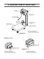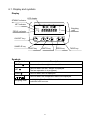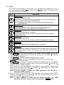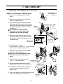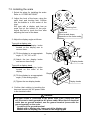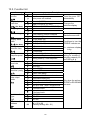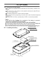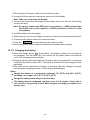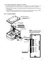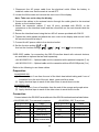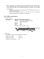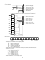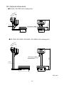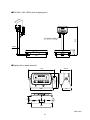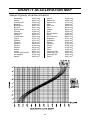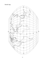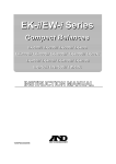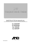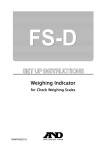
1
SW Series Super Washdown Scales SW-6KS / SW-15KS SW-15KM / SW-30KM / SW-60KM / SW-150KM SW-60KL / SW-150KL 1WMPD4002080A Warning Definition The warning described in this manual has the following meaning: DANGER An imminently hazardous situation which, if not avoided, will result in death or serious injury. © 2011 A&D Company, Limited. All rights reserved. No part of this publication may be reproduced, transmitted, transcribed, or translated into any language in any form by any means without the written permission of A&D Company, Limited. The contents of this manual and the specifications of the instrument covered by this manual are subject to change for improvement without notice. CONTENTS 1. COMPLIANCE ..................................................................................................... 3 2. INTRODUCTION .................................................................................................. 4 3. FEATURES........................................................................................................... 4 4. PRECAUTIONS.................................................................................................... 5 4.1. Installing the scale ..................................................................................... 5 4.2. Operating the scale ................................................................................... 5 4.3. Cleaning the scale..................................................................................... 6 5. UNPACKING ........................................................................................................ 6 6. DESCRIPTION OF EACH PART.......................................................................... 7 6.1. Display and symbols ................................................................................. 8 6.2. Keys .......................................................................................................... 9 7. SETTING UP ...................................................................................................... 10 7.1. Attaching the display pole to the base ..................................................... 10 7.2. Installing the scale ....................................................................................11 8. BASIC OPERATION .......................................................................................... 12 8.1. Turning the power ON and OFF .............................................................. 12 8.2. Selecting a weighing unit......................................................................... 13 8.3. Basic weighing operation......................................................................... 13 8.4. Weight display resolution......................................................................... 14 9. COUNTING MODE............................................................................................. 15 10. COMPARATOR ................................................................................................ 16 10.1. The formula to compare ........................................................................ 17 10.2. Entering the comparator values............................................................. 18 11. AUTO-TARE FUNCTION.................................................................................. 19 12. CALIBRATION ................................................................................................. 20 12.1. Calibration mode ................................................................................... 20 12.2. Gravity acceleration correction .............................................................. 21 12.3. Calibration using a weight ..................................................................... 22 1 12.4. Restoring the factory set values ............................................................ 23 13. FUNCTIONS..................................................................................................... 24 13.1. Setting the parameters .......................................................................... 24 13.2. Restoring the function settings to the factory set values ....................... 24 13.3. Function list ........................................................................................... 25 14. OPTIONS ......................................................................................................... 27 14.1. Using the HC-02i battery ....................................................................... 27 14.1.1. Installing the battery ...................................................................27 14.1.2. Charging the battery...................................................................28 14.2. SW-03 RS-232C / RELAY OUTPUT...................................................... 29 14.2.1. Installing SW-03 .................................................................................... 29 14.2.2. SW-03 specifications ........................................................................... 31 14.2.3. Command mode ................................................................................... 34 14.3. SW-04 RS-422 / 485 ............................................................................. 39 14.3.1. Installing SW-04 .................................................................................... 39 14.3.2. SW-04 specifications ........................................................................... 40 15. MAINTENANCE ............................................................................................... 43 15.1. Notes on maintenance........................................................................... 43 15.2. Error codes............................................................................................ 43 16. SPECIFICATIONS............................................................................................ 44 16.1. Specifications ........................................................................................ 44 16.2. External dimensions .............................................................................. 46 GRAVITY ACCELERATION MAP .......................................................................... 48 2 1. COMPLIANCE Compliance with FCC rules Please note that this equipment generates, uses and can radiate radio frequency energy. This equipment has been tested and has been found to comply with the limits of a Class A computing device pursuant to Subpart J of Part 15 of FCC rules. These rules are designed to provide reasonable protection against interference when equipment is operated in a commercial environment. If this unit is operated in a residential area it might cause some interference and under these circumstances the user would be required to take, at his own expense, whatever measures are necessary to eliminate the interference. (FCC = Federal Communications Commission in the U.S.A.) Classification of protection provided by enclosures The equipment is designed to comply with the IP Code of IEC 60529. The “IP69K” is explained as follows: “IP” International Protection. “6” Against ingress of solid foreign objects. Dust-tight. No ingress of dust. “9K” Against ingress of water with harmful effects. High pressure water jets directed against the enclosure from any direction shall have no harmful effects. (DIN40050 Part 9) NSF listed Applicable only to the NSF Certified models. The NSF Certified models have the NSF Mark attached on the display. The equipment is certified and listed to NSF/ANSI Standard 169 by NSF International. NSF International evaluated the equipment and certified that it is compliant with food protection and sanitation requirements for the design, construction and materials. (NSF = National Sanitation Foundation) 3 2. INTRODUCTION This manual describes how the SW Series Super Washdown Scales work and how to get the most out of them in terms of performance. Please read this manual completely before using the scale. 3. FEATURES The SW Series Super Washdown Scales have the following features: Dust-tight and water-tight construction, complying with IP69K. The weighing platforms and weighing pans are made of stainless steel (SUS304). The weighing platforms are designed for easy cleaning and not to collect dust. Three sizes of weighing platform are available. Employing touch-sensitive keys enabled the display to be covered with a plastic sheet, resulting in better dust-tight and water-tight performance. When a key is touched, the corresponding LED, above that key, turns on to indicate that the key has been touched. A bright LED display, with a broad viewing angle. Three types of weight display resolution are available to cover various applications, 1/3,000, 1/6,000 (1/7,500 for some models) and 1/12,000 (or 1/15,000 for some models). (To be selected in the function setting.) Note: The weight display resolution of the Legal for Trade models is fixed. The selection in the function setting is not available. The counting mode easily counts the number of objects of the same weight. The comparator mode compares the displayed value (weight value) with the previously set comparator values and indicates the results by the large and bright LED display. The optional comparator relay output (SW-03) can output the results as a relay signal. The auto-tare function, used with the comparator mode, automatically tares and displays “OK” for a certain amount of sample and repeats this process with the next weighing. Available weighing units are kg (kilogram), g (gram), Ib (pound), oz (ounce), Ib-oz (pound and ounce) and pcs (pieces for the counting mode). The optional RS-232C serial interface (SW-03) or optional RS-422/485 serial interface (SW-04) can transmit the weight value to a printer or personal computer. The optional sealed lead acid (SAL) battery (HC-02i) can be installed, allowing the scale to be used where an AC power source is not available. 4 4. PRECAUTIONS 4.1. Installing the scale DANGER • Ground the scale so that the user will not be subject to an electric shock. • The base frame is connected to the power GND (EXC-) inside the load cell. Be sure to earth ground the AC power cable. When the AC electrical outlet has no ground terminal, use the ground terminal (screw with the ground symbol) on the scale. Location of the ground terminal Models with a display pole: lower part of the display pole Models with no display pole: bottom of the weighing pan • Do not handle the AC power cable with wet hands. • The AC plug is not water-resistant. Use an electrical outlet located at a place where the plug will not get wet. • Even when the optional sealed lead acid (SLA) battery (HC-02i) is used, be sure to prevent the AC plug from getting wet. • Do not handle the cables carelessly. • Do not install the scale where flammable or corrosive gas is present. Consider the following conditions to get the most from your scale. Install the scale where the temperature and relative humidity are stable, with no drafts or vibration. Install the scale on a solid and level surface. Do not install the scale in direct sunlight. Do not install the scale near heaters or air conditioners. Do not install the scale near equipment which produces magnetic fields. Do not install the scale in a place where it is possible to be charged with static electricity, or where the relative humidity is lower than 45% RH. Insulators such as plastic are often charged with static electricity. Use a stable power source. Calibrate the scale before use or after having moved it to another location. In addition, calibrate it periodically to maintain the accuracy. (Refer to “12. CALIBRATION”). 4.2. Operating the scale Periodically ensure that the scale weighs correctly. Calibrate the scale periodically to maintain the weighing accuracy (Refer to “12. CALIBRATION”). Do not place anything on the pan that is beyond the weighing capacity. Do not apply a shock load to the scale. Touch the keys only with a finger. Confirm zero before each weighing to prevent possible error. 5 4.3. Cleaning the scale Do not disassemble the scale. Do not use solvents to clean the scale. The scale can be washed with water completely. 5. UNPACKING When unpacking, check whether all of the following items are included: Instruction manual SW series scale The scale components are different depending on the type of scale. With a display pole (no display stand) With a display stand (no display pole) With no display pole or display stand 6 6. DESCRIPTION OF EACH PART Display Display pole AC power cable Spirit level Pole support foot Weighing pan Ground terminal (The above illustration is for scales with a display pole.) Leveling foot Display rear side Display knobs Display knobs Display stand (The above illustration is for scales with a display pole.) (The above illustration is scales with a display stand.) 7 6.1. Display and symbols Display LED display STABLE indicator NET indicator LO OK HI pcs ZERO indicator Weighing units g STABLE NET kg ZERO oz lb ON/OFF key ON/OFF SAMPLE PRINT UNITS ZERO TARE SAMPLE key PRINT key UNITS key ZERO key TARE key Symbols Symbol Description STABLE ○ Turns on when the weight value is stable. NET ○ Turns on when the NET weight is displayed. (The tare operation is in progress.) ZERO ○ Turns on when zero is displayed. Turns on when the comparator results are displayed. Weighing units “pcs”, “g”, “kg”, “oz” and “lb” are available. A selected unit turns on. 8 6.2. Keys The keys are touch-sensitive. Three levels of key sensitivity are available and can be set in the function setting “key“. When set to “key 2 “ (High), the keys can be operated with a gloved finger. Key Description ON/OFF key Turns the power ON or OFF. When turned ON, the scale will be automatically set to zero (power-on zero). To turn the power OFF, press and hold the key. Note: If pressing the key does not turn the power ON immediately, keep pressing the key. SAMPLE key In the counting mode (“pcs”), goes to the unit weight storing mode. Press and hold to go to the comparator value setting mode. PRINT key Outputs the weight value to the printer. In the setting mode, this key is used to increase the value of the selected blinking digit by one. UNITS key Switches the weighing unit. In the setting mode, this key is used to shift the blinking digit to the right. ZERO key Zeroes the scale and sets the display to zero. (See below.) TARE key Subtracts the tare (container) weight placed on the weighing pan. (See below.) In the setting mode, this key is used to store the setting value and proceed to the next step. The ZERO key will zero the scale if the weight value is within ±2% of the weighing capacity (kg) around the power-on zero point. The ZERO indicator turns on. (ZERO operation) The ZERO key functions while the weight value is stable. Even with “-e” displayed, when the STABLE indicator turns on, pressing the ZERO key will zero the scale. The TARE key will tare the scale and subtract the weight to zero as a tare weight when the weight is a positive stable value. In this case the ZERO and NET indicators turn on. (TARE operation) When the tare is removed while the tare operation is in progress and the scale returns to the zero point, the ZERO and NET indicators turn on. In this case the displayed tare value will be negative. (Note: In some countries or areas, the ZERO indicator will not turn on during the TARE operation.) When the tare is removed while the TARE operation is in progress and the ZERO operation described above is performed, the tare operation previously done is cleared and the NET indicator turns off. (Note: In some countries or areas, after the ZERO operation, the TARE operation will not be cleared without pressing the TARE key.) 9 7. SETTING UP 7.1. Attaching the display pole to the base Lower part of the display pole 2 SW-M / L series with a display pole 1. Remove the weighing pan from the base. 2. Remove the 4 screws from the lower part of the display pole. 3. Insert the display pole under the base while pulling out the cable into the base and align the cable opening positions of the pole and the base. (See “3” in the illustration.) Do not pull the cable forcibly. Take care not to pinch the cable between the pole and the base. 4. Align the screw holes of the pole and the base. Using the 4 screws removed at step 2 to secure the display pole to the base firmly. Base, seen from above 4 3. Pull out the cable Base 3. Insert Cable Lower part of the display pole 5. Lay the base on its side. Remove the 4 screws (“5” in the illustration) and remove the pole support foot. 6. Pull the excess cable out of the base. (See “6” in the illustration.) Take care not to damage the cable. And make sure the cable has no slack. 6 5 7 7. Pull the cable out to the pole side. 5 (See “7” in the illustration.) Pole support foot Cable 8. Put the bundle of cable back into the display pole. (See “8” in the illustration.) Display pole 9 9. Using the 4 screws removed at step 5, secure the pole support foot to the display pole. 10. Return the base to the upright position and place the weighing pan on the base. 10 8 Bundle 9 7.2. Installing the scale 1. Select the place for installing the scale. Refer to “4. PRECAUTIONS”. 2. Adjust the level of the base, using the spirit level and leveling feet. Confirm that the bubble is in the center of the level. SW type with a display pole has an extra foot at the bottom of the pole. Adjust this foot to touch the floor after adjusting the level of the base. Leveling foot Spirit level The size and shape depends on the scale model. 3. Adjust the display angle as follows. Type with a display pole (1) Rotate the two display knobs located on the display rear to remove them. Display (2) Tilt the display to an appropriate angle, 0°, 30°, 60° or 90°. (3) Attach the two display knobs and secure them firmly. Display knobs Type with a display stand (1) Loosen the two display knobs located on the sides of the display. Display (2) Tilt the display to an appropriate angle. (Free setting angle) (3) Tighten the two display knobs. Display knobs 4. Confirm that nothing is touching the keys and connect the AC power cable to an electrical outlet. DANGER • The base frame is connected to the power GND (EXC-) inside the load cell. Be sure to earth ground the AC power cable. When the AC electrical outlet has no ground terminal, use the ground terminal (screw with the ground symbol) on the scale. Location of the ground terminal Models with a display pole: lower part of the display pole Models with no display pole: bottom of the weighing pan 11 8. BASIC OPERATION 8.1. Turning the power ON and OFF 1. Press the ON/OFF key to turn the power ON. All the display symbols appear and the scale waits for the weight value to become stable. When the optional sealed lead acid (SLA) battery (HC-02i) is used: After all the display symbols appear, the battery capacity status is displayed for about 1.5 seconds as shown below. Level Display Battery capacity status 1 Full capacity “bat ooo” 2 “bat _oo” 3 “bat __o” 4 “bat ___” No capacity (Low battery) At level 3, prepare to recharge the battery. At level 4, recharge the battery immediately. (Refer to “14.1. Using the HC-02i battery”.) After the weight value internally becomes stable, the display turns off for a moment, and then, zero is displayed along with the ZERO indicator (power-on zero). If the weight value is unstable, “------” is displayed. Check if anything touches the weighing pan, or if there is a strong draft or vibration. Eliminate the cause of the error. The range for power-on zero is within ±50% (within ±10% for the Legal for Trade models) of the weighing capacity (kg) around the calibrated zero point. If the power is turned ON while there is a load beyond this range, “------” is displayed. Remove the load from the weighing pan. If the scale is to be turned ON with some item loaded, performing a zero calibration with the item loaded will allow the scale to turn ON that way. (Refer to “12. CALIBRATION”.) In this case, make sure that the total weight of the item loaded at power-on and the object to be weighed is within the weighing capacity. 2. Press and hold the ON/OFF key to turn the power OFF. Auto power-off function The auto power-off function automatically turns the power OFF, if zero is displayed for approximately 5 minutes. Refer to “13.3. Function list” to set “poff”. 12 8.2. Selecting a weighing unit In the weighing mode, press the UNITS key to select a weighing unit. Each time the UNITS key is pressed, the unit changes as shown below. Ib oz Ib-oz kg or g pcs Using the function setting “Ut-g”, “kg” and “g” can be switched. Ut-g 0 : To display “kg”. Ut-g 1 : To display “g”. Notes • For the SW-60K / 150K, the function setting “Ut-g” is not available and only “kg” is displayed. • Not all the units are available, depending on the area or country. 8.3. Basic weighing operation 1. Press the ON/OFF key to turn the power ON. The unit used last before turning off appears. 2. Select a weighing unit using the UNITS key. 3. When the display doesn’t show zero, press the ZERO key to set the display to zero. 4. When using a tare (container), place the container on the weighing pan, and press the TARE key to set the display to zero. 5. Place the object to be weighed on the weighing pan or in the container, and wait for the STABLE indicator to turn on and read the value. Container Weighing pan Press NET ZERO Object to be weighed 6. Remove the object from the weighing pan. The ZERO key will zero the scale if the weight value is within ±2% of the weighing capacity (kg) around the power-on zero point. The ZERO indicator turns on. STABLE NET The TARE key will tare the scale and subtract the weight to zero as a tare weight when the weight is a positive value. The NET and ZERO indicators turn on. (Note: In some countries or areas, the ZERO indicator will not turn on during the TARE operation.) Weighing is possible up to the weighing capacity. When a tare is used, weighing is possible up to the weighing capacity less the tare weight value. The ZERO and TARE keys function only when the weight values are stable. 13 8.4. Weight display resolution The weight display resolution is a ratio of the minimum display to the weighing capacity. The SW series has three types of weight display resolution, as shown below. Normal: High: Maximum: 1/3,000 1/6,000 or 1/7,500 (depending on the weighing capacity) 1/12,000 or 1/15,000 (depending on the weighing capacity The factory setting is the high resolution. Select the resolution that suits your own application in the function setting “re5o”. For details about the minimum display and the weighing capacity, refer to “16.1. Specifications”. The weight display resolution of the Legal for Trade models is fixed. The selection in the function setting “re5o” is not available. In the counting mode, the scale works with the maximum resolution regardless of the weight display resolution selected in the function setting “re5o”. 14 9. COUNTING MODE Determines a unit weight (the weight of one piece) from a known sample quantity, and calculates how many pieces are on the weighing pan using the unit weight. The unit weight is maintained even if the power is turned OFF. 1. Press the UNITS Press key to select “pcs”. (“pcs” = pieces) 2. Press the SAMPLE key to enter the sample unit weight storing mode. The numerical value on the left indicates the number of samples. ZERO 3. To change the number of samples, press the PRINT key. It may be set to 5, l0, 20, 50 or l00. ZERO 4. When “-“ appears at the right side of the number of samples, press the ZERO key to zero the scale . If necessary, place a container on the weighing pan, and press the TARE1 key. Confirm that the right side of the number of samples shows zero. Press Press Container Weighing pan 5. Place the correct number of samples on the weighing pan or in the container. 6. Confirm that the STABLE indicator is turned on. Press the SAMPLE key to calculate and store the unit weight. Remove the samples. The scale is set to count objects with this unit weight. The total weight of samples should be more than shown below, regardless of the number of samples. Weighing capacity of 6 kg: 0.005 kg Weighing capacity of 15 kg: 0.01 kg Weighing capacity of 30 kg: 0.02 kg Weighing capacity of 60 kg: 0.05 kg Weighing capacity of 150 kg: 0.1 kg If not, the display shows “lo ut” and returns to the display of step 5. Increase the number of samples (step 3) and try again. If the SAMPLE key is pressed before the weight above is reached, the scale exits the sample unit weight storing mode and returns to the counting mode display. 7. Place the objects to be counted on the weighing pan. 15 Number of samples Press NET ZERO Samples STABLE Press Confirm zero 10. COMPARATOR Five-level, three-level and seven-level (portion weighing mode) comparators are available. Each comparator mode compares the weight value against the preset limit values and outputs the results using LEDs (yellow / green / red). When the optional comparator relay output (SW-03) is installed, the results are output as a relay signal. • Five-level comparator mode: Uses four comparator values to compare the weight value and outputs results in five levels of LOLO, LO, OK, HI and HIHI. • Three-level comparator mode: Uses two comparator values (upper and lower limit values) to compare the weight value and outputs results in three levels of LO, OK and HI. • Seven-level comparator mode (portion weighing mode): Uses six comparator values to compare the weight value and outputs results in seven levels of over in the negative value, level 1 (LOLO), level 2 (LO), Level 3 (OK), level 4 (HI), level 5 (HIHI) and over in the positive value. To use the comparator modes, the function settings “Cp-l” and “Cp” must be specified and the comparator values must be set. Using the function setting “Cp-l”, select a comparator mode. 0: five-level comparator mode 1: three-level comparator mode 2: Seven-level comparator mode (portion weighing mode) Using the function setting “Cp”, select comparison conditions. 0: No comparison (comparator mode disabled). 1: To compare all data. 2: To compare all stable data. 3: To compare all data which are more than or equal to +5d, or less than or equal to -5d. 4: To compare stable data which are more than or equal to +5d, or less than or equal to -5d. 5: To compare all data which are more than or equal to +5d. 6: To compare stable data which are more than or equal to +5d. d = minimum display in kg (Refer to “16.1. Specifications”.) Also in the counting mode, “d” is equal to the minimum display of kg mode. 16 10.1. The formula to compare Comparison is performed using the formula listed below and the results are output. Five-level comparator mode Results Comparison formula LED display Displayed value < LOLO limit value LOLO (Or over in the negative value) ( Red LED on) LO Displayed value < LO limit value OK LO limit value ≤ Displayed value ≤ HI limit value HI HI limit value < Displayed value HIHI HIHI limit value < Displayed value (Or over in the positive value) Three-level comparator mode Results Comparison formula Displayed value < LO limit value LO (Or over in the negative value) OK LO limit value ≤ Displayed value ≤ HI limit value HI HI limit value < Displayed value (Or over in the positive value) ( Yellow LED on) ( Green LED on)) ( Yellow LED on) ( Red LED on) LED display ( Red LED on) ( Green LED on)) ( Red LED on) Seven-level comparator mode (portion weighing mode) Results Comparison formula LED display Displayed value < Level 1 lower limit value None (Or over in the negative value) ( No LEDs on) LOLO (Level 1) Displayed value < Level 2 lower limit value ( Red LED on) LO (Level 2) Displayed value < Level 3 lower limit value ( Yellow LED on) OK Level 3 lower limit value ≤ Displayed value ≤ (Level 3) Level 3 upper limit value ( Green LED on)) HI (Level 4) Level 3 upper limit value < Displayed value ( Yellow LED on) HIHI (Level 5) Level 4 upper limit value < Displayed value ( Red LED on) Level 5 upper limit value < Displayed value None (Or over in the positive value) ( No LEDs on) The comparator values are common to the weighing and counting mode. Ignore the decimal point when setting the comparator values. For example, when the weighing capacity is 6 kg and the setting value is “001000”: Display mode Limit value Capacity / Minimum display Normal resolution kg 1.000 kg 6.000 kg / 0.002 kg High resolution kg 1.000 kg 6.000 kg / 0.001 kg Maximum resolution kg 0.1000 kg 6.0000 kg / 0.0005 kg Normal resolution oz 100.0 oz 210.0 oz / 0.1 oz High resolution oz 10.00 oz 210.00 oz / 0.05 oz Maximum resolution oz 10.00 oz 210.00 oz / 0.02 oz Counting mode 1000 pcs The comparator values are maintained even if the power is turned OFF. Judgment order of comparison is from the top row to the bottom in the comparator mode tables The entered comparator values are not judged. Even if the upper limit value is less than the lower limit value, no error will be output. 17 10.2. Entering the comparator values 1. In the weighing mode, press and hold the SAMPLE key to enter the comparator value setting mode. 2. Enter the comparator values using the following keys. UNITS To shift the blinking digit to the right. PRINT To increase the value of the blinking digit by one. SAMPLE To switch the polarity. Each time the key is pressed, “-“ is turned on and off at the leftmost digit. When on, the value is negative. TARE To confirm and store the setting value. 3. When the setting is complete, “end” is displayed and the scale returns to the weighing mode. (At this time, power-on-zero is not performed.) Five-level comparator mode Three-level comparator mode 18 Seven-level comparator mode 11. AUTO-TARE FUNCTION The SW series has an auto-tare function to be used with the comparator mode enabled. Using this function in check weighing, the scale automatically tares, then displays “OK” for a certain amount of sample and repeats this process for the next weighing. Start with display zero after tare operation. Place or take away objects until the comparison result will show OK. When the stable display is maintained for the duration specified in the function setting “at-t”, the scale will automatically tare the weight, show zero and be ready for next weighing. In some countries or areas, the auto-tare function can not be used on the Legal for Trade models and the selection in the function settings “at”, “at-t” and “at-f” is not available. To use the auto-tare function, set the function settings below. Cp 1: Compare all weighing data (other settings may be used depending on the application). at 1: Auto-tare function enabled. at-t 0 ~ 9: Select the timing to tare automatically to avoid the wrong tare operation, for example; too early to tare, to take a longer time to go to the next weighing. Take-away check weighing “Cp-p 1” (Example with “Cp-l 0” setting) Take-away check weighing (negative comparison) is the way to compare the negative weight while taking away objects from a container. Set the function “Cp-p 1” together with the auto-tare function enabled “at 1”. In this operation mode, the scale operates as “take-away the objects” Æ “OK and stable” Æ “auto-tare” Æ “take-away the objects” Æ ······. In this setting, the polarity of LOLO, LO, HI, and HIHI limit values are ignored and the scale shows the comparator results as below. Note: To start the take-away check weighing, be sure to use the TARE key to tare the weight of the container filled with objects. The ZERO key may zero the display, and the scale goes below the zero point by taking out the objects. Then, the auto-tare function does not work. When the function “at-f 1 Tares the initial (container) weight.” is selected: To start the auto-tare function, usually the container (filled with objects) will be placed on the weighing pan and its weight must be tared using the TARE key. When the function “at-f 1” is selected, the scale will tare the initial (container) weight automatically. When all load on the weighing pan is removed, the scale will return to the zero point and the tare weight will be automatically cleared. If the scale does not return to the zero point, press the ZERO key to clear the tare weight. If the scale is equipped with the optional RS-232C serial interface (SW-03) or optional RS-422/485 serial interface (SW-04), the OK weighing data only can be output automatically. Set the function setting “prt 5”. 19 12. CALIBRATION Adjusts the scale for accurate weighing. Calibrate the scale in the following cases. When the scale is first installed. When the scale has been moved. When the ambient environment has changed. For regular calibration. Note: Calibration can not be performed on the Legal for Trade models. 12.1. Calibration mode The calibration mode has the following three functions. • Gravity acceleration correction • Calibration using a weight • Restoring the factory set values How to enter the calibration mode Method 1: 1. Make sure that the scale is in the weighing mode (displaying “kg” (“g”), “lb”, “oz” or “pcs”). 2. Press and hold the TARE key until the gravity acceleration value (in this example, “G 9.7985”) appears and release the key. Note: The above operation is disabled for the Legal for Trade models. The Legal for Trade models can not enter the calibration mode. Method 2: 1. Make sure that the scale is in the weighing mode (displaying “kg” (“g”), “lb”, “oz” or “pcs”). 2. Remove the screw protection caps on the load cell panel on the bottom of the display. Loosen the four screws and then open the load cell panel. The calibration (CAL) switch is located inside. 3. Press the CAL switch. The scale displays the gravity acceleration value (in this example, “G 9.7985”). Note: The load cell panel for the Legal for Trade models has been sealed using wire locked screws. The CAL switch does not work on the Legal for Trade models. Calibration (CAL) switch Load cell panel Wire locked screws (Legal for Trade models) 20 Press the UNITS to select an item key and press the TARE to execute it. key To exit from the calibration mode, press the ZERO1 key or the CAL switch. The scale returns to the weighing mode. 12.2. Gravity acceleration correction When the scale is first used or has been moved to another location, it should be calibrated using a calibration weight. But if a calibration weight is not available, the gravity acceleration correction will compensate the scale. Change the gravity acceleration value stored in the scale to the value of the area where the scale will be used. Refer to the gravity acceleration map at the end of this manual. Note: Gravity acceleration correction is not required when the scale will be calibrated using a calibration weight at the place where it is to be used. 1. Refer to “12.1. Calibration mode” to enter the calibration mode. The gravity acceleration value is displayed. 2. Press the TARE key to enter the gravity acceleration value setting mode. Press 3. Change the displayed value using the following keys. UNITS To shift the blinking digit to the right. PRINT To increase the value of the blinking digit by one. Press 4. Press the TARE key. The setting value is stored and “end” is displayed. 5. When calibration using a calibration weight is to be performed, go to step 3 of “12.3. Calibration using a weight”. To finish the setting procedure, press the ZERO1 key or the CAL switch. The scale returns to the weighing mode. 21 Press 12.3. Calibration using a weight Prepare a weight, preferably a weight with the same value as the weighing capacity of the scale to be calibrated. Note that the calibration weight value can be changed. 1. Turn the power ON and warm up the scale for at least half an hour. Change the function setting “poff” or place something on the weighing pan to disable the auto power-off function. 2. Refer to “12.1. Calibration mode” to enter the calibration mode. The gravity acceleration value is displayed. 3. Press the UNITS key and display “Cal”. Press 4. Press the TARE key until “Cal 0” is displayed. Confirm that nothing is placed on the weighing pan and wait for the STABLE indicator to turn on. 5. Press the TARE key. The scale calibrates the zero point and displays the value of the calibration weight (SPAN calibration). Press The calibration weight value is equal to the weighing capacity. (factory setting) When you enter with “kg” (“g”) or “pcs” mode, the value is in “kg”. With “Ib” or “oz”, then “Ib”. Press If SPAN calibration is not to be performed, turn the power OFF to exit from the calibration procedure. 6. To calibrate with a weight different from the weighing capacity, change the displayed value using the following keys. UNITS To shift the digit that is blinking to the right. PRINT To increase the value of the blinking digit by one. Using a weight with the same value as the weighing capacity is recommended. If other weights are used, use one with a value greater than two-thirds of the capacity. Press Calibration weight Weighing pan 7. Place the calibration weight with the same value as displayed on the weighing pan, and wait for the STABLE indicator to turn on. Press 8. Press the TARE key. The scale calibrates SPAN and “end” is displayed. To finish the setting procedure, press the ZERO1 key or the CAL switch. The scale returns to the weighing mode. Note: If the scale will be moved to another location, set the gravity acceleration value for the new location and calibrate the scale according to the procedure above. Refer to the previous section to set the gravity acceleration value. 22 12.4. Restoring the factory set values If the gravity acceleration value or calibration weight value is changed unintentionally, restore those values to the factory set values, as follows. 1. Refer to “12.1. Calibration mode” to enter the calibration mode. The gravity acceleration value is displayed. 2. Press the “ClrC” . . UNITS key twice to display Press twice 3. Press the TARE key to display “ClrC no” with “no” blinking. Press 4. Press the PRINT key. “ClrC no” changes to “ClrC go” with “go” blinking. Press To cancel the restoring procedure, press the ZERO key. The display returns to step 2. 5. When “ClrC go” is displayed, press the TARE key. The factory set values are restored and “end” is displayed. To finish the setting procedure, press the ZERO1 key or the CAL switch. The scale returns to the weighing mode. 23 Press 13. FUNCTIONS The scale has function settings to specify the scale performance. The parameters set in the function settings are maintained even if the power is turned OFF. Parameter Item While holding down, 13.1. Setting the parameters press 1. Turn the power OFF. 2. Press and hold the TARE key and press the ON/OFF key to turn the power ON. The software version is displayed. “∗∗∗” indicates the software version number. 3. After about one second, the item is displayed. 4. Change the item or parameter using the following keys. UNITS To display the next item. PRINT To increase the value of the blinking digit by one (to change the parameter). Press When the parameter is changed, the STABLE indicator turns off. When changed 5. Press the TARE key to store the setting value. After “end”, the power is turned OFF automatically. Press To cancel the setting procedure without storing the value, press the ZERO key. The power is turned OFF automatically. 13.2. Restoring the function settings to the factory set values 1. Turn the power OFF. 2. Press and hold the TARE key and press the ON/OFF key to turn the power ON. Only release the ON/OFF key and hold the TARE key until “Clrf no” with “no” blinking is displayed. 3. Press the PRINT key. “Clrf no” changes to “Clrf go” with “go” blinking. 4. When “Clrf go” is displayed, press the TARE key. The factory set values are restored. After “end”, the power is turned OFF automatically. To cancel the restoring procedure, press the ZERO key. The power is turned OFF automatically.. 24 Press Press 13.3. Function list Item Auto power-off function poff Parameter Description 0 Auto power-off disabled 1 Weight display resolution 0 1 2 re5o (See Note) Weighing unit 0 Auto power-off enabled Normal (1/3,000) High (1/6,000 or 1/7,500) Maximum (1/12,000 or 1/15,0 00) kg Ut-g 1 g Zero tracking 0 Zero tracking function disabled 1 Stability band 0 width 1 2 5t-b (See Note) Stability 0 detection time 1 2 5t-t Stability 0 Response speed 1 Zero tracking function enabled ±0.5d (width 1d) ±1.0d (width 2d) ±2.0d (width 4d) 0.5 second 1.0 second 2.0 seconds Weak stability / fast response Normal stability / normal response Cond Strong stability / slow response trc 2 Serial interface baud rate 0 1 2 bp5 Serial interface 0 data bits / parity 1 2 btpr Serial interface 0 Data output 1 mode 2 prt 3 4 5 6 Serial interface Type 5if Serial interface Address adr 0 1 2 ## 2400 bps 4800 bps 9600 bps 7 bits / EVEN 7 bits / ODD 8 bits / Non parity Stream mode / Command mode Command mode only Print key mode / Command mode Auto-print mode +/- data / Command mode Auto-print mode + data/ Command mode Auto-print mode +/- data and OK / Command mode Auto-print mode + data and OK / Command mode RS-232C RS-422 RS-485 ## = 00 to 99 (Factory setting: ## = 01) 25 Turns the power OFF automatically Changes the minimum display Tracks the zero drift Conditions to turn the STABLE indicator on d = minimum display in kg Filtering. Factory setting for models of weighing capacity 60 and 150 kg is 1. Only when the options, RS-232C or RS-422/485, are used. Item Serial interface Response Parameter aCk 1 Reply to commands Comparator mode 0 1 2 0 1 2 3 4 5 6 0 1 Five-level Three-level Seven-level (portion weighing mode) Comparator disabled Sets comparison Compares all data conditions Compares all stable data Compares all data of ≥ +5d or ≤ -5d d = minimum display Compares stable data of ≥ +5d or ≤ -5d in kg Compares data of ≥ +5d Compares stable data of ≥ +5d Low Medium Cp-l Comparison conditions Cp Key sensitivity key 0 2 Auto-tare function at (See Note) Auto-tare timing at-t (See Note) Description No reply except data to commands High 0 Auto-tare function disabled 1 Auto-tare function enabled 0 1 2 3 4 5 6 7 8 9 Immediately after OK and stable 0.5 second after OK and stable 1.0 second after OK and stable 1.5 seconds after OK and stable 2.0 seconds after OK and stable 2.5 seconds after OK and stable 3.0 seconds after OK and stable 4.0 seconds after OK and stable 5.0 seconds after OK and stable 6.0 seconds after OK and stable Auto-tare for the 0 initial weight 1 at-f(See Note) Function disabled Normal/Negative 0 comparison Normal comparison Cp-p Only when the options, RS-232C or RS-422/485, are used. Tares the initial (container) weight. Refer to “11. AUTOTARE FUNCTION” Timing to tare automatically after the comparison OK and stable weight. To be used with “at 1”. Automatic operation Refer to “11. AUTONegative comparison for take-away TARE FUNCTION” 1 check weighing Factory setting d = minimum display in kg, the minimum mass that can be weighed in kg Even the counting mode uses “d” for judgment. (Note: In some countries or areas, “re5o ”, “5t-b ”, “at”, “at-t” and “at-f” are not available for the Legal for Trade models.) 26 14. OPTIONS 14.1. Using the HC-02i battery The scale can be operated with a sealed lead acid (SLA) battery, available as an option. The scale (with no other options) can be operated continuously for about 90 hours with a fully charged battery. The battery will take about 15 hours to be fully charged. The battery life will vary depending on how the scale is used, the ambient temperature and so on. A battery, NP4-6 (6V, 4Ah), manufactured by YUASA, is commercially available. Caution • There will be risk of leakage, fire or explosion if the battery is connected improperly or replaced with the incorrect type. • Dispose of a used battery according to the local laws and regulations. • Do not handle the battery with wet hands. Take much care not to get the battery wet. • Do not install the battery under high temperatures and high humidity. • Even when the battery is used, be sure to prevent the AC plug from getting wet. M4 screw (10 pcs) 14.1.1. Installing the battery Display rear cover Battery NP4-6 “+” terminal (RED) “-” (BLACK) wire “+” (RED) wire “-” terminal (BLACK) Display 27 1. Disconnect the AC power cable from the electrical outlet. 2. Loosen the M4 screws and remove the rear cover of the display. Note: Take care not to drop the display. 3. Connect the wires inside the display to the battery with much care so that nothing touches the keys. Note: Be sure to connect the RED wire to the positive (+ / RED) terminal and the BLACK wire to the negative (- / BLACK) terminal. Or there is a risk of explosion. 4. Install the battery into the display. 5. Attach the rear cover to the display and secure it with the screws loosened at step 2. 6. Connect the AC power cable to the electrical outlet. 7. Press the ON/OFF key and check that the scale turns ON. 8. Disconnect the AC power cable and check that the scale works normally. 14.1.2. Charging the battery When the display shows “lb” (Low battery), the battery voltage is low and should be recharged. Turn the scale OFF and connect the AC power cable to an electrical outlet. The charging process will start. Charging will be performed when the AC power cable is connected to an electrical outlet and the scale is turned OFF. If the scale is turned ON, trickle charging will be performed. The scale can be used while the battery is charging. After fully charged, the scale will change the charging process to trickle charge automatically. Notes • Charge the battery at a temperature between 0°C (32°F) and 40°C (104°F), preferably, at a range of 5°C (41°F) to 35°C (95°F) . • Charge the battery when using for the first time. • The battery must be recharged regularly, every 3 to 6 months, if the scale is not used for a long period of time. More frequent recharging is required in a warmer area. 28 14.2. SW-03 RS-232C / RELAY OUTPUT This interface allows the SW scale to be connected to an AD-8121 printer or a personal computer, and the relay outputs for comparator results are also available. When SW-03 is installed, the dust-tight and water-tight performance of the scale will be degraded. SW-03 includes an interface board, two connector cables (7 and 10 pins), two cable glands (for cable diameter 3.5 to 7.0 mm) and two screws (M3x8). 14.2.1. Installing SW-03 M4 screw (10 pcs) Display rear cover M3x8 screws Interface board Connector cables Cable glands Note Six-pin or seven-pin terminal block. Pin 7 of the seven-pin terminal block is not used. To the external device Peel 6 mm (AWG 26~16) Terminal block 29 1.LOLO 2.LO 3.OK 4.HI 5.HIHI 6.COM Not used 1.RXD 2.TXD 3.DSR 4.SG 5.SHLD 1. Disconnect the AC power cable from the electrical outlet. When the battery is installed, make sure that the scale is turned OFF. 2. Loosen the M4 screws and remove the rear cover of the display. Note: Take care not to drop the display. 3. Connect the cables to the external device through the cable gland to the terminal blocks on the interface board. 4. Attach the connector cables (7 and 10 pins), provided with SW-03, to the connectors on the interface board and the connectors on the main board inside the display. 5. Secure the interface board using the two M3 x 8 screws provided with SW-03. 6. Tighten the cable glands and attach the rear cover to the display and secure it with the screws loosened at step 2. 7. Connect the AC power cable to the electrical outlet. 8. Set the function setting “5if” to “0”. And set the function settings “bp5”, “btpr”, “prt” and “aCk” as necessary. RS-232C cables, for connecting the SW-03 interface board with external devices, are available as options that are sold separately. • AX-KO3285-320 --- Optional cable unit for connection with a personal computer (3 m) • AX-KO3341-320 --- Optional cable unit for connection with an AD-8121B printer (3 m) Refer to the following to use these cables. Preparation AX-KO3285-320 (1) Remove about 6 mm from the end of the black heat shrink tubing and 6 mm of insulation from the end of the red, black, green and blue wires. (2) Apply electrical tape to each of the other wires to avoid short circuits. AX-KO3341-320 (1) Remove about 6 mm of insulation from the end of the orange and purple wires. (2) Apply electrical tape to each of the other wires to avoid short circuits. Connection Connect wires to the RS-232C terminal block of the SW-03 interface board as listed below. AX-KO3285-320: To a personal computer SW-03 terminal block Cable 1. RXD --Black (Pin 3) 2. TXD --Red (Pin 2) 3. DSR --Blue (Pin 6) 4. SG --Green (Pin 5) 5. SHLD --Black heat shrink tubing-covered wire 30 AX-KO3341-320: To a printer SW-03 terminal block Cable 1. RXD 2. TXD --- Orange (Pin 3) 3. DSR 4. SG --- Purple (Pin 7) 5. SHLD When connecting to an external device with hardware flow control, communication will be impossible using a cable without RTS and CTS connected. In that case, connect RTS and CTS. This will disable hardware flow control, but will enable communication. • When the connector of an external device is a D-Sub 9-pin connector, pin 7 is RTS and pin 8 is CTS. • When the AX-KO3285-320 cable is used, RTS and CTS are internally connected and the above operation is unnecessary. 14.2.2. SW-03 specifications RS-232C interface Transmission form Data format Asynchronous, bi-directional, half-duplex Baud rate: 2400, 4800, 9600 bps Data bits: 7 bits + parity 1bit (EVEN / ODD) or 8 bits (non parity) Start bit: 1 bit Stop bit: 1 bit Code: ASCII Terminator: CRLF (CR:0Dh, LF:0Ah) LSB 0 1 Start bit 2 3 4 MSB 5 6 Data bits Relay output The maximum rating of the replay output is as follows. Maximum voltage: 50V DC Maximum current: 100 mA DC Maximum ON resistance: 8Ω 31 Parity bit 1 (-15V~-5V) 0 (5V~15V) Stop bit Circuit diagram 1 Receive data RXD 2 Transmit data TXD 3 Data set ready DSR 4 Signal ground SG 5 Shield SHLD SW is designed as DCE (Data Communication Equipment). LOLO 1 Relay output LOLO 2 Relay output LO 3 Relay output OK 4 Relay output HI 5 Relay output HIHI 6 Relay common COM LO OK HI HIHI SW inside Solid sate relay Data format S T , + 0 0 Header 0 0 0 Data . 0 0 _ k Unit g CR LF Terminator There are 4 headers for the weighing data. ST: QT: US: OL: Stable weighing data Stable counting data Unstable weighing data Out of weighing range The data consists of 9 characters including the polarity and decimal point. There are 5 units. _ k g: Weighing mode “kg” _ _ g: Weighing mode “g” _ l b: Weighing mode “lb” _ o z: Weighing mode “oz” _ PC: Counting mode “pcs” As a terminator, CRLF is always output. 32 Data example Weighing data “kg” (+) S T , + 0 0 1 2 . 3 4 5 _ k g CR LF Weighing data “g” (-) S T , - 0 0 0 0 1 2 3 4 _ _ g CR LF Counting data “pcs” (+) Q T , + 0 0 0 1 2 3 4 5 _ P C CR LF Out of weighing range (+) O L , + 9 9 9 9 . 9 9 9 _ k g CR LF Data output mode (prt) Command mode The scale is controlled by commands that come from an external device such as a personal computer. For details, refer to “14.2.3. Command mode”. Stream mode (prt 0) Data is sent continuously. The data update rate is approximately 10 times per second, the same as the display refresh rate. There will be no output during the setting procedures. Print key mode (prt 2) When the weight display is stable, data is sent by pressing the PRINT key. At this time, the display flashes once to indicate that the data is sent. Auto-print mode +/- data (prt 3) When the weight display is stable at ±5d (d = minimum display in kg) and above +5d or below -5d, the data is sent. The next transmission can not occur until after the weight display falls between –4d and +4d. Auto-print mode + data (prt 4) When the weight display is stable at +5d (d = minimum display in kg) and above, the data is sent. The next transmission can not occur until after the weight display falls +4d or below. Auto-print mode +/- data and OK (prt 5) When the weight display is stable and OK as a comparison result at ±5d (d = minimum display in kg) and above +5d or below -5d, the data is sent. The next transmission can not occur until after the weight display falls between –4d and +4d. Auto-print mode + data and OK (prt 6) When the weight display is stable and OK as a comparison result at +5d (d = minimum display in kg) and above, the data is sent. The next transmission can not occur until after the weight display falls +4d or below. Baud Rate (bp5) Select the baud rate according to the device to be connected. 2400 bps (bp5 0) Select 2400 bps to connect to an AD-8121 printer. 4800 bps (bp5 1) 9600 bps (bp5 2) 33 14.2.3. Command mode In the command mode, the scale is controlled by commands that come from an external device such as a personal computer. Command List Command Q Z T U ?H3 ?H2 ?H1 ?L1 ?L2 ?L3 Description Send data immediately. Zero the scale when the weight is stable. Tare the scale when the weight is stable. Switch the weighing unit. When the five-level comparator mode is used: Not used When the three-level comparator mode is used: Not used When the seven-level comparator mode is used: Send the current level 5 upper limit value. When the five-level comparator mode is used: Send the current HIHI limit value. When the three-level comparator mode is used: Send the current HI limit value. When the seven-level comparator mode is used: Send the current level 4 upper limit value. When the five-level comparator mode is used: Send the current HI limit value. When the three-level comparator mode is used: Not used When the seven-level comparator mode is used: Send the current level 3 upper limit value. When the five-level comparator mode is used: Send the current LO limit value. When the three-level comparator mode is used: Not used When the seven-level comparator mode is used: Send the current level 3 lower limit value. When the five-level comparator mode is used: Send the current LOLO limit value. When the three-level comparator mode is used: Send the current LO limit value. When the seven-level comparator mode is used: Send the current level 2 lower limit value. When the five-level comparator mode is used: Not used When the three-level comparator mode is used: Not used When the seven-level comparator mode is used: Send the current level 1 lower limit value. 34 Remarks Same as the ZERO key. Same as the TARE key. Same as the UNITS key. Send a setting value. Function settings Five-level (Cp-l 0) Three-level (Cp-l 1) Seven-level (Cp-l 2) Command Description When the five-level comparator mode is used: Not used Remarks H3 When the three-level comparator mode is used: Not used When the seven-level comparator mode is used: Set the level 5 upper limit value. When the five-level comparator mode is used: Set the HIHI limit value. H2 When the three-level comparator mode is used: Set the HI limit value. When the seven-level comparator mode is used: Set the level 4 upper limit value. When the five-level comparator mode is used: Set the HI limit value. When the three-level comparator mode is used: Not used When the seven-level comparator mode is used: Set the six-digit value excluding Set the level 3 upper limit value. the polarity and decimal point When the five-level comparator mode is used: Set the LO limit value. When the three-level comparator mode is used: Not used When the seven-level comparator mode is used: Set the level 3 lower limit value. When the five-level comparator mode is used: Set the LOLO limit value. When the three-level comparator mode is used: Set the LO limit value. When the seven-level comparator mode is used: Set the level 2 lower limit value. When the five-level comparator mode is used: Not used When the three-level comparator mode is used: Not used When the seven-level comparator mode is used: Set the level 1 lower limit value. H1 L1 L2 L3 35 Command examples (“_” indicates “Space” (20H).) The examples below are for the function setting “aCk 1 “ (Reply to commands). Request the weight data. Command Q CR LF Reply S T , + 0 0 1 2 . 3 4 5 _ k g CR LF Stable positive data U S , + 0 0 0 7 . 8 9 0 _ k g CR LF Unstable positive data O L , + 9 9 9 9 . 9 9 9 _ k g CR LF ‘E’ display Zero the scale. (No reply for the function setting “aCk 0 “.) Command Z CR LF Reply Z CR LF The scale is in a condition that zero operation is possible. Tare the scale. (No reply for the function setting “aCk 0 “.) Command T CR LF Reply T CR LF The scale is in a condition that tare operation is possible. Switch the weighing unit. (No reply for the function setting “aCk 0 “.) Command U CR LF Reply U CR LF Switch the weighing unit to the next weighing unit. Five-level comparator mode…Not used Three-level comparator mode…Not used Seven-level comparator mode…Send the current level 5 upper limit value. Command ? H 3 CR LF Reply H 3 , + 0 0 0 5 0 0 C R LF Five-level comparator mode…Send the current HIHI limit value. Three-level comparator mode…Send the current HI limit value. Seven-level comparator mode…Send the current level 4 upper limit value. Command ? H 2 CR LF Reply H 2 , + 0 0 0 4 0 0 C R LF Five-level comparator mode…Send the current HI limit value. Three-level comparator mode…Not used Seven-level comparator mode…Send the current level 3 upper limit value. Command ? H 1 CR LF Reply H 1 , + 0 0 0 3 0 0 C R LF 36 Five-level comparator mode…Send the current LO limit value. Three-level comparator mode…Not used Seven-level comparator mode…Send the current level 3 lower limit value. Command ? L 1 CR LF Reply L 1 , + 0 0 0 2 0 0 C R LF Five-level comparator mode…Send the current LOLO limit value. Three-level comparator mode…Send the current LO limit value. Seven-level comparator mode…Send the current level 2 lower limit value. Command ? L 2 CR LF Reply L 2 , + 0 0 0 1 0 0 C R LF Five-level comparator mode…Not used Three-level comparator mode…Not used Seven-level comparator mode…Send the current level 1 lower limit value. Command ? L 3 CR LF Reply L 3 , + 0 0 0 0 0 0 C R LF Five-level comparator mode…Not used Three-level comparator mode…Not used Seven-level comparator mode…Set the level 5 upper limit value. (No reply for the function setting “aCk 0 “.) Set the six-digit value excluding the polarity and decimal point. Command H 3 , + 0 0 0 5 0 0 CR LF Reply H 3 , + 0 0 0 5 0 0 C R LF Five-level comparator mode…Set the HIHI limit value. Three-level comparator mode…Set the HI limit value. Seven-level comparator mode…Set the level 4 upper limit value. (No reply for the function setting “aCk 0 “.) Set the six-digit value excluding the polarity and decimal point. Command H 2 , + 0 0 0 4 0 0 CR LF Reply H 2 , + 0 0 0 4 0 0 C R LF Five-level comparator mode…Set the HI limit value. Three-level comparator mode…Not used Seven-level comparator mode…Set the level 3 upper limit value. (No reply for the function setting “aCk 0 “.) Send the six-digit value excluding the polarity and decimal point. Command H 1 , + 0 0 0 3 0 0 CR LF Reply H 1 , + 0 0 0 3 0 0 C R LF 37 Five-level comparator mode…Set the LO limit value. Three-level comparator mode…Not used Seven-level comparator mode…Set the level 3 lower limit value. (No reply for the function setting “aCk 0 “.) Send the six-digit value excluding the polarity and decimal point. Command L 1 , + 0 0 0 2 0 0 CR LF Reply L 1 , + 0 0 0 2 0 0 C R LF Five-level comparator mode…Set the LOLO limit value. Three-level comparator mode…Set the LO limit value. Seven-level comparator mode…Set the level 2 lower limit value. (No reply for the function setting “aCk 0 “.) Send the six-digit value excluding the polarity and decimal point. Command L 2 , + 0 0 0 1 0 0 CR LF Reply L 2 , + 0 0 0 1 0 0 C R LF Five-level comparator mode…Not used Three-level comparator mode…Not used Seven-level comparator mode…Set the level 1 lower limit value. (No reply for the function setting “aCk 0 “.) Send the six-digit value excluding the polarity and decimal point. Command L 3 , + 0 0 0 0 0 0 CR LF Reply L 3 , + 0 0 0 0 0 0 C R LF Replies to the commands other than examples above when the function setting “aCk 1 “ is selected. The scale is not in a state where a command could be executed. Then, the scale will reply “I”. Command Z CR LF Reply I CR LF The scale is not in a condition that zero operation is possible. Command does not exist for the scale. Then, the scale will reply “?”. Command B CR LF Reply ? CR LF The scale received an undefined command. When the function setting “aCk 0 “ is selected, undefined commands are ignored and no reply is sent. 38 14.3. SW-04 RS-422 / 485 This interface allows a personal computer to connect and control up to 16 scales. When SW-04 is installed, the dust-tight and water-tight performance of the scale will be degraded. SW-04 unit includes an interface board, a connector cable (10 pins), two cable glands (for cable diameter 3.5 to 7.0 mm) and two screws (M3x8). 14.3.1. Installing SW-04 M4 screw (10 pcs) Display rear cover M3x8 screws Interface board Connector cable Cable glands Peel Connect to an external device other SW 6 mm (AWG 26~16) Terminal block 39 1.SDA 2.SDB 3.RDA 4.RDB 5.TRM 6.SG 7.SHLD 1.SDA 2.SDB 3.RDA 4.RDB 5.TRM 6.SG 7.SHLD The installation procedure is the same as for SW-03. Refer to “14.2.1. Installing SW03”. Set the function settings “bp5”, “btpr”, “prt”, “5if”, “adr” and “aCk” as necessary. Before using SW-04, the function setting “5if” must be set to specify whether RS422 or RS-485 is used. To connect more than one scale to a computer, set a different address to each scale using the function setting “adr”. 14.3.2. SW-04 specifications RS-422/485 interface Transmission system EIA RS-422 / 485 Transmission form Asynchronous, bi-directional, half-duplex Data format Baud rate: 2400, 4800, 9600 bps Data bits: 7 bits + parity 1bit (EVEN / ODD) or 8 bits (non parity) Start bit: 1 bit Stop bit: 1 bit Code: ASCII Terminator: CRLF (CR:0Dh, LF:0Ah) LSB 0 Start bit 1 2 3 4 Data bits MSB 5 6 Parity bit A-B 1 (-2V~-5V) 0 (2V~5V) Stop bit Circuit diagram 1 SDA (RS-422 Out) 2 SDB (RS-422 Out) 3 RDA (RS-422 In / RS-485 In-Out) 4 RDB (RS-422 In / RS-485 In-Out) 5 TRM (Termination) 6 SG (Signal ground) 100Ω 7 SHLD (Shield) 1 SDA (RS-422 Out) 2 SDB (RS-422 Out) 3 RDA (RS-422 In / RS-485 In-Out) 4 RDB (RS-422 In / RS-485 In-Out) 5 TRM (Termination) 6 SG (Signal ground) 7 SHLD (Shield) 40 Example of connection RS-422 Host computer Terminator (may be built in the computer). RS-485 Terminator (may be built in the computer). RDA RDB SDA SDB Host computer SW Address 01 SDA SDB RDA RDB TRM SW Address 01 SDA SDB RDA RDB TRM SW Address 02 SDA SDB RDA RDB TRM SW Address 02 SDA SDB RDA RDB TRM SW Address 16 SDA SDB RDA RDB TRM SW Address 16 SDA SDB RDA RDB TRM A B Connect TRM to RDB at the farthest SW from the host computer. The polarity (A, B) of the host computer signal depends on the computer model. Check the technical manual of the computer. Data format The data format for the RS-422/485 is the same as the RS-232C except the following: When used with the function setting “5if 1” (RS-422) or “5if 2” (RS-485), set a different address to each scale using the function setting “adr##”. ((##=01 to 99) Start all commands with “@##” (## is the address of the scale to send a command). All replies from the scale start with “@##”. The format after “@##” is the same as the RS-232C, both in commands and replies. When used with the RS-485 interface (function setting: “5if 2”), note the following: • When sending commands continuously, leave an interval of 500 ms or more between commands. • Do not use stream mode (function setting: “prt 0”) when sending commands. Commands will not be received correctly and will be invalid. 41 Command examples (“_” indicates “Space” (20H).) The examples below are for the function setting “aCk 1 “ (Reply to commands). The address ## = 23. Request a weight data. Command @ 2 3 Q CR LF Reply @ 2 3 S T , + 0 0 1 2 . 3 4 5 _ k g CR LF Stable data @ 2 3 U S , + 0 0 0 7 . 8 9 0 _ k g CR LF Unstable data @ 2 3 O L , + 9 9 9 9 . 9 9 9 _ k g CR LF “E” display Zero the scale. (No reply for the function setting “aCk 0 “.) Command @ 2 3 Z CR LF Reply @ 2 3 Z CR LF The scale is in a condition that zero operation is possible. Send the current LO limit value. Command @ 2 3 ? L 1 CR LF Reply @ 2 3 L 1 , + 0 0 0 2 0 0 CR LF 42 15. MAINTENANCE 15.1. Notes on maintenance Do not disassemble the scale. Contact your local A&D dealer if the scale needs service or repair. Use the original packaging for transportation. Do not use organic solvents to clean the scale. Use a warm lint free cloth dampened with a mild detergent. Calibrate the scale periodically to maintain the weighing accuracy. 15.2. Error codes Overload error Indicates that an object beyond the weighing capacity has been placed on the weighing pan. Remove the object from the weighing pan. Underload error Indicates that the weight sensor receives a strong upward force. Check if the weighing pan is touching anything or if there is anything in the base. There is a possibility that the weight sensor or internal circuit may have a problem. Unit weight error Indicates that the sample weight is too light to set the unit weight in the counting mode. CAL error Indicates that the calibration procedure is canceled because the calibration weight is too light. Check that the weighing pan is installed properly and the mass of the calibration weight. Low battery Indicates that the HC-02i battery is depleted. Charge the battery immediately. Other There may be an internal malfunction. (∗ indicates an error number.) Note: If the error persists or other errors occur, contact your local A&D dealer. 43 16. SPECIFICATIONS 16.1. Specifications MODEL Weighing capacity kg Minimum display Weighing capacity g Minimum display Weighing capacity lb Minimum display Weighing capacity oz Minimum display Weighing capacity Minimum display Number of samples Maximum count Minimum unit weight Repeatability (Std. deviation) Linearity Sensitivity drift Ib-oz Display Display update Operating conditions Power supply Weighing pan size Dimensions (Models with a display pole) Mass (approximately) (Models with a display pole) Calibration weight (factory setting) SW-6KS SW-15KS SW-15KM SW-30KM 6 15 15 30 0.002 0.005 0.005 0.01 0.001 * 0.002 * 0.002 * 0.005 * 0.0005 0.001 0.001 0.002 6000 15000 15000 30000 2 5 5 10 1* 2* 2* 5* 0.5 1 1 2 13 33 33 66 0.005 0.01 0.01 0.02 0.002* 0.005* 0.005* 0.01* 0.001 0.002 0.002 0.005 210 520 520 1050 0.1 0.2 0.2 0.5 0.05* 0.1* 0.1* 0.2* 0.02 0.05 0.05 0.1 13 33 33 66 0.1 0.1 0.1 0.1 5 (can be changed to 10, 20, 50 or 100) pieces 120,000 pcs 150,000 pcs 150,000 pcs 150,000 pcs 0.00005 kg 0.0001 kg 0.0001 kg 0.0002 kg 0.001 kg 0.002 kg 0.002 kg 0.005 kg ±0.002 kg ±0.005 kg ±0.005 kg ±0.01 kg ±20 ppm / °C (5°C to 35°C / 41°F to 95°F) Weight display: 7 segment LED display (character height 14.6 mm) Comparison results: red / yellow / green / yellow / red LED 10 times per second -10°C to 40°C / 14°F to 104°F AC main (100 V to 240 V, 50/60 Hz, 20 VA) or optional SLA battery (continuous operation of 90 hours depending on how the scale is used) 250 x 250 mm / 9.8 x 9.8 in. 300 x 380 mm / 11.8 x 15.0 in. 250 (W) x 480 (D) x 353.5 (H) mm 300 (W) x 601 (D) x 722.5 (H) mm 9.8 (W) x 18.9 (D) x 13.9 (H) in. 11.8 (W) x 23.7 (D) x 28.4 (H) in. 7.7 kg / 17.0 Ib 6 kg 12 lb 15 kg 30 lb * Factory setting 44 13.0 kg / 28.7 Ib 15 kg 30 lb 30 kg 60 lb MODEL Weighing capacity kg SW-60KM SW-150KM SW-60KL SW-150KL 60 150 60 150 0.02 0.05 0.02 0.05 0.01 * 0.02 * 0.01 * 0.02 * 0.005 0.01 0.005 0.01 130 330 130 330 0.05 0.1 0.05 0.1 0.02* 0.05* 0.02* 0.05* 0.01 0.02 0.01 0.02 2100 5200 2100 5200 1 2 1 2 0.5* 1* 0.5* 1* 0.2 0.5 0.2 0.5 130 330 130 330 1 1 1 1 5 (can be changed to 10, 20, 50 or 100) pieces 120,000 pcs 150,000 pcs 120,000 pcs 150,000 pcs 0.0005 kg 0.001 kg 0.0005 kg 0.001 kg Minimum display Weighing capacity lb Minimum display Weighing capacity oz Minimum display Weighing capacity Minimum display Number of samples Maximum count Minimum unit weight Repeatability (Std. deviation) Linearity Sensitivity drift Ib-oz Display Display update Operating conditions Power supply Weighing pan size Dimensions (Models with a display pole) Mass (approximately) (Models with a display pole) Calibration weight (factory setting) 0.01 kg 0.02 kg 0.01 kg 0.02 kg ±0.02 kg ±0. 05 kg ±0.02 kg ±0. 05 kg ±20 ppm / °C (5°C to 35°C / 41°F to 95°F) Weight display: 7 segment LED display (character height 14.6 mm) Comparison results: red / yellow / green / yellow / red LED 10 times per second -10°C to 40°C / 14°F to 104°F AC main (100 V to 240 V, 50/60 Hz, 20 VA) or optional SLA battery (continuous operation of 90 hours depending on how the scale is used) 300 x 380 mm / 11.8 x 15.0 in. 390 x 530 mm / 15.4 x 20.9 in. 300 (W) x 601 (D) x 722.5 (H) mm 390 (W) x 751 (D) x 722.5 (H) mm 11.8 (W) x 23.7 (D) x 28.4 (H) in. 15.4 (W) x 29.6 (D) x 28.4 (H) in. 13.0 kg / 28.7 Ib 60 kg 120 lb 150 kg 300 lb 16.2 kg / 35.7 Ib 60 kg 120 lb 150 kg 300 lb * Factory setting Options HC-02i SAL Sealed Lead Acid battery (YUASA NP4-6 recommended) SW-03 RS-232C / Relay output SW-04 RS-422 / 485 Note: The options, SW-03 and SW-04, can not be used at the same time. 45 16.2. External dimensions 0/ 60 /9 0 ° φ42.7 353.5 0/3 ●SW-6KS / SW-15KS (with a display pole) 98 AC power cable 202 179 0/ 3 ●SW-15KM / SW-30KM / SW-60KM / SW-150KM (with a display pole) 0/ 60 /9 0 ° 722.5 AC power cable 117.5 φ42.7 228 331 Unit: mm 46 /6 0 /9 0° 0/ 3 0 ●SW-60KL / SW-150KL (with a display pole) 722.5 AC power cable 126.5 φ42.7 481 318 ●Display with a stand attached 315 152.5 197.5 135.9 90 283 6-φ5 110 70 250 Unit: mm 47 GRAVITY ACCELERATION MAP Values of gravity at various locations Amsterdam Athens Auckland NZ Bangkok Birmingham Brussels Buenos Aires Calcutta Cape Town Chicago Copenhagen Cyprus Djakarta Frankfurt Glasgow Havana Helsinki Kuwait Lisbon London (Greenwich) Los Angeles Madrid 9.813 m/s2 9.807 m/s2 9.799 m/s2 9.783 m/s2 9.813 m/s2 9.811 m/s2 9.797 m/s2 9.788 m/s2 9.796 m/s2 9.803 m/s2 9.815 m/s2 9.797 m/s2 9.781 m/s2 9.810 m/s2 9.816 m/s2 9.788 m/s2 9.819 m/s2 9.793 m/s2 9.801 m/s2 9.812 m/s2 9.796 m/s2 9.800 m/s2 Manila Melbourne Mexico City Milan New York Oslo Ottawa Paris Rio de Janeiro Rome San Francisco Singapore Stockholm Sydney Taichung Tainan Taipei Tokyo Vancouver, BC Washington DC Wellington NZ Zurich 48 9.784 m/s2 9.800 m/s2 9.779 m/s2 9.806 m/s2 9.802 m/s2 9.819 m/s2 9.806 m/s2 9.809 m/s2 9.788 m/s2 9.803 m/s2 9.800 m/s2 9.781 m/s2 9.818 m/s2 9.797 m/s2 9.789 m/s2 9.788 m/s2 9.790 m/s2 9.798 m/s2 9.809 m/s2 9.801 m/s2 9.803 m/s2 9.807 m/s2 World map 49 MEMO 50 MEMO 51 MEMO 52 3-23-14 Higashi-Ikebukuro, Toshima-ku, Tokyo 170-0013 JAPAN Telephone: [81] (3) 5391-6132 Fax: [81] (3) 5391-6148 A&D ENGINEERING, INC. 1756 Automation Parkway, San Jose, California 95131 U.S.A. Telephone: [1] (408) 263-5333 Fax: [1] (408)263-0119 A&D INSTRUMENTS LIMITED <UK Office> Unit 24/26 Blacklands Way, Abingdon Business Park, Abingdon, Oxfordshire OX14 1DY United Kingdom Telephone: [44] (1235) 550420 Fax: [44] (1235) 550485 A&D INSTRUMENTS LIMITED <German Sales Office> Große Straße 13 b 22926 Ahrensburg Deutschland Telefon: [49] (0) 4102 459230 Telefax: [49] (0) 4102 459231 A&D Australasia Pty Ltd. 32 Dew Street, Thebarton, South Australia 5031 AUSTRALIA Telephone: [61] (8) 8301-8100 Fax: [61] (8) 8352-7409 A&D KOREA Limited 한국에이.엔.디(주) 대한민국 서울시 영등포구 여의도동 36-2 맨하탄 빌딩 8층 ( 8th Floor, Manhattan Bldg. 36-2 Yoido-dong, Youngdeungpo-ku, Seoul, KOREA ) 전화: [82] (2) 780-4101 팩스: [82] (2) 782-4280 A&D RUS CO., LTD. Компания ЭЙ энд ДИ РУС 121357, Российская Федерация, г.Москва, ул. Верейская, дом 17 ( Bldg. 17, Vereyskaya st., Moscow, 121357 RUSSIAN FEDERATION ) тел.: [7] (495) 937-33-44 факс: [7] (495) 937-55-66 A&D Instruments India Private Limited ( 509, Udyog Vihar, Phase- , Gurgaon - 122 016, Haryana, India ) : 91-124-4715555 : 91-124-4715599