1
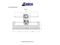
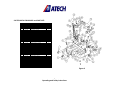
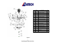
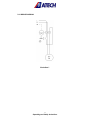
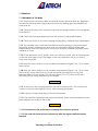
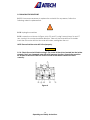
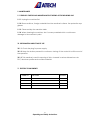
LIBRA-02 P
PORTABLE COPY ROUTER
USER’S MANUAL
1
Operating and Safety Instructions
CONTENTS
Page
1. General Information
3
1.1. Introduction
3
1.2. Manufacturer
3
2. Machine’s Description and Purpose of Use
3
2.1. Machine’s description
3
2.2. Technical features
5
2.3. Overall dimensions
6
2.4. Part lists and technical drawings
7
2.5. Wiring diagram
9
3. Safety
10
3.1. Safety information
10
3.2. Accident prevention
10
3.3. General safety information
11
4. Transport of the machine
13
5. Installation of the machine
13
5.1. Preparation
13
5.2. Electric connection
14
6. Machine’s safety information
14
7. Operation
15
7.1. Beginning of the work
15
8. Changing the router bit
16
9. Maintenance
17
9.1. Periodic checks and maintenance at the end of the working day
17
10. Information about faulty use
17
11. Electric components
17
2
Operating and Safety Instructions
1. GENERAL INFORMATION
1.1. INTRODUCTION
The user’s manual given by the manufacturer contains necessary information about the
machine parts. Each machine operator should read these instructions carefully, and the
machine should be operated after fully understanding them.
Safe and efficient use of the machine for long term depends on understanding and
following the instructions contained in this manual. The technical drawings and details
contained in this manual constitute a guide for the operator.
1.2. DISTRIBUTOR
ATech Machine, Inc.
10752-A Tucker Street – Beltsville, MD 20705 USA
Phone: +1-301-595-1816 Fax: +1-301-560-6627
Website: www.ATechMachinery.com
E-mail: [email protected]
In case of any technical problem please contact your nearest ATECH dealer, or ATECH
head office through the above mentioned phone fax or e-mail address.
Technical labels with the model description of the machine are fixed onto the front side
of each machine.
The machine’s serial number and manufacturing year are stipulated on the technical
label.
2. MACHINE’S DESCRIPTION and PURPOSE OF USE
2.1. MACHINE’S DESCRIPTION
Portable copy router machine designed to open lock, handle, hinge and window
fastening slots onto vinyl (PVC) and Aluminum profiles.
Machine has been designed in accordance with the CE Safety Directives.
Clamping and copy routing operation is carried out manually.
Channels in different dimensions can be opened independently from copying.
3
Operating and Safety Instructions
Please mention the below mentioned data in all your correspondence regarding the
machine with the manufacturer and/or your ATECH dealer.
*Machine model
*Machine’s serial number
*Voltage and frequency
*Name of dealer where machine was purchased
*Date of purchase
*Description of the machine fault
*Average daily operation period
4
Operating and Safety Instructions
2.2. TECHNICAL FEATURES
Technical
Features
(American)
LIBRA-02 P
1200W
120V 60Hz
23000 rpm
22x22x18"
60 lb
1200W
230V 50Hz
23000 rpm
55x55x46 cm
27 kg
Technical
Features
(Metric)
LIBRA-02 P
5
Operating and Safety Instructions
2.3. OVERALL DIMENSIONS
Figure-1
6
Operating and Safety Instructions
2.4. TECHNICAL DRAWINGS and PART LISTS
NO
1
2
3
4
5
6
7
8
9
10
11
12
13
14
19
21
22
24
28
29
30
31
32
35
36
37
38
40
41
42
43
44
45
46
47
48
49
63
68
ORDER NO.
111-062
550-009
550-010
177-017
111-064
550-004
111-060
172-029
192-008
141-138
111-050
224-002
170-023
172-012
144-002
111-050
141-069
172-013
180-006
141-060
172-014
141-073
176-002
141-057
141-058
141-202
180-008
176-026
141-066
111-061
172-026
172-025
172-024
193-006
141-059
111-065
223-003
172-027
273-002
171-070
PART NAME
CLAMP HOUSING
HANDLE 1
HANDLE 3
HOUSING
MECHANIC CLAMP
SET SQUARE
M8x35 HEXAG. SCREW
LINEAR BEARING25x35x40
TIGHTENING HANDLE
FOOT
FOOT PLASTIC
DIAM. 6mm WASHER
M6x20 HEXAG. SCREW
COLUMN SHAFT
COLUMN HOUSING LEFT
HOUSING SHAFT CONNECTION
M6x10 HEXAG. SCREW
M6x8 SCREW
COPY TEMPLATE
M6x16 HEXAG. SCREW
M10x170 DOWEL
M10 BOLT
12mm SUPPORT SHAFT
SUPPORT SHAFT BUSHING
TIGHTENING HANDLE
M8x12 SCREW
M8x20 HEXAG. SCREW
MOVEMENT PLATE
MOVEMENT ANKLE
M8x20 HEXAG. SCREW
M8x16 HEXAG. SCREW
M8x30 HEXAG. SCREW
25x20x20 SINTER BUSHE
LEVER SHAFT
LEVER
BAKALITE LEVER AS-3 12x15
M8x25 HEXAG. SCREW
GAS SPRING 600643201 200N
GAS SPRING CONNECT.
QTY
2
2
4
2
2
2
1
4
4
2
1
4
6
8
2
1
2
6
2
1
2
1
3
1
2
2
4
2
2
2
2
2
4
2
1
1
1
1
1
2
Figure-2
7
Operating and Safety Instructions
3
13
14
15
16
17
23
24
25
26
27
33
34
39
51
52
53
54
55
57
65
66
67
69
71
73
Figure-3
8
Operating and Safety Instructions
ORDER
550-010
177-03
172-012
223-004
141-071
141-068
141-072
172-013
172-017
111-074
550-014
111-059
192-006
144-003
111-054
144-004
111-068
145-017
141-175
141-136
141-062
141-063
550-011
176-014
191-001
141-061
PART NAME
HANDLE 3
DIA 6 mm WASHER
M6x20 HEXAG. SCREW
BAKALITE LEVER A5-12
SWITCH HANDLE BOLT
UPPER LIMITING PIN
SNAP HOUSING SHEET
M6x10 HEXAG. SCREW
M6x30 HEXAG. SCREW
CONNECTOR PROTECT.
1200 W ELECTRIC MOTORU
AXIS HOUSING
LINEAR BEARING PP20x28x30
AXIS BEARING HOUSING
HEAD
UPPER AXIS SHAFT
SNAP HOUSING
SNAP HOUSING FIX. PLATE
INTERMEDIATE BUSHE
BUTTERFLY SCREW
ROUTER BIT HOLDER SHAFT
ROUTER BIT HOLDER
SNAP GROUP
FIBER BOLT
6002 2Z BEARING
ROUTER BIT HOLDER BOLT
QTY
4
6
8
1
1
2
2
6
4
1
1
1
6
2
1
2
2
2
4
2
1
1
2
2
1
1
2.6. WIRING DIAGRAM
Illustration-1
9
Operating and Safety Instructions
3. SAFETY
3.1. SAFETY INFORMATION
The symbols shown hereunder are necessary to be read with special attention.
Not reading or observing of them may cause damage to the equipment or personal
injury
IMPORTANT
The IMPORTANT symbol above is one telling to apply special care and to be careful at
carrying out the specified operation.
CAUTION !
The CAUTION! Symbol above warns you against specific dangers, and requires to read
the text. Not observing may cause damage to the equipment.
DANGER WARNING
The DANGER WARNING above warns you against specific dangers, and definitely
requires the text to read. Not observing may result in serious bodily injury.
Please read the user’s manual carefully before using the machine or carrying out
maintenance.
3.2. PREVENTION OF ACCIDENTS
3.2.1 Our machines are manufactured in accordance with EN 60204-1 and EN 292-2 CE
safety directives, which cover national and international safety directives.
3.2.2 It is the task of the employer to warn his staff against accident risks, to train them
on prevention of accidents, to provide for necessary safety equipment and devices for
the operator’s safety.
10
Operating and Safety Instructions
3.2.3 Before starting to work with the machine, the operator should check the features
of the machine, learn all details of the machine's operation.
3.2.4 The machine should be operated only by staff members, who have read and
understood the contents of this manual.
3.2.5 All directives, recommendations and general safety rules contained in this manual
have to be observed fully. The machine cannot be operated in any way for purposes
other than those described herein. Otherwise, the manufacturer shall not be deemed
responsible for any damages or injuries. And such circumstances would lead to the
termination of the warranty.
3.3. GENERAL SAFETY INFORMATION
3.3.1. The power cable should be led in such a way that nobody can step on it or
nothing can be placed on it. Special care has to be taken regarding the inlet
and outlet sockets.
3.3.2. If the power cable should be damaged during operation, don't touch and
unplug it. Never use damaged power cables.
3.3.3. Don’t overload machines for drilling and cutting. Your machine will operate
more safely with power supply in accordance with the stipulated values.
3.3.4. Don’t place your hands between parts in motion.
3.3.5. Use protective eye glasses and ear plugs. Don't wear oversize clothes and
jewels. These can be caught by moving parts.
3.3.6. Keep your working place always clean, dry and tidy for accident prevention
and safe operation.
11
Operating and Safety Instructions
3.3.7. Use correct illumination for the safety of the operator. (ISO 8995-89 The
Lighting of Indoor Work Systems)
3.3.8. Don't leave anything on the machine.
3.3.9. Don’t use any materials other than those recommended by the
manufacturer for cutting operations on the machine.
3.3.10. Ensure that the work piece is clamped appropriately by the machine's
clamp or vice.
3.3.11. Ensure safe working position, always keep your balance.
3.3.12. Keep your machine always clean for safe operation. Follow the instructions
at maintenance and replacement of accessories. Check the plug and cable
regularly. If damaged, let it replace by a qualified electrician. Keep handles and
grips free of any oil and grease.
3.3.13. Unplug first, before conducting and maintenance works.
3.3.14. Ensure that any keys or adjustment tools have been removed before
operating the machine.
3.3.15. If you are required to operate the machine outside, use only appropriate
extension cables.
3.3.16. Repairs should be carried out by qualified technicians only. Otherwise,
accidents may occur.
3.3.17. Before starting a new operation, check the appropriate function of
protective devices and tools, ensure that they work properly. All conditions have
to be fulfilled in order to ensure proper operation of your machine. Damaged
protective parts and equipment have to be replaced or repaired properly (by the
manufacturer or dealer).
3.3.18. Don’t use machines with improper functioning buttons and switches.
3.3.19. Don’t keep flammable, combustive liquids and materials next to the machine
and electric connections.
12
Operating and Safety Instructions
4. TRANSPORT OF THE MACHINE
IMPORTANT
4.1.1. The transport should be done by qualified personnel only.
4.1.2. The machine should be transported by lifting with proper equipment (not
touching the ground during the transport).
4.1.3. Movable parts on the machine should be fixed before carrying out the transport
through the support shaft fixing bushing (Figure-5, No. 36).
4.1.4. Please keep the original packing of the machine for use at future transports.
5. INSTALLATION OF THE MACHINE
5.1. PREPARATION
5.1.1. The machine’s overall dimensions are given under Figure 1. Place the machine
onto an even ground, or onto the double tray tool cabinet delivered as optional
equipment.
5.1.2. The machine should be located approx. 30 cm away from the rear wall. The
power connection plug of the machine is located on the rear side of the machine.
5.1.3. The machine should be placed on even and solid ground.
5.1.4. At our portable copy router model LIBRA-02 P, connect the profile support bars by
screwing the bars No. 74 and 75 into each other (Figure-5). Fix the set square fence No.
76 with the special screw No. 3 onto the support bars. Insert the assembled support bars
into the slot on the set square No. 7, and tighten with the special screw No. 10.
No
Stock No / Part name
QTY
3
150-010 HANDLE 1
5
7
111-060 SQUARE
1
10
141-138 TIGHTENING HANDLE
2
15
1
48
223-004 BUTTON SWITCH
141-058 SUPPORTING PIVOT
FIXED PART
111-065 ARM
1
74
141-065 SQUARE SUPPORTING PIVOT 1
1
75
141-064 SQUARE SUPPORTING PIVOT 2
1
76
111-055 SQUARE SUPPORT
1
36
2
Figure-5
13
Operating and Safety Instructions
5.2. ELECTRIC CONNECTION
5.2.1The electric cable socket has to be in accordance with the socket on the
machine.
5.2.2 Your machine has to be used with 230V 50Hz voltage.
5.2.3 Use the machine’s plug with a grounded socket.
CAUTION !
5.2.4. Check the supply voltage. The source voltage must be in accordance with the
data on the machine’s label.
6. MACHINE’S SAFETY INFORMATION
6.1.1. The machine should not be used without the transparent protection shield in front
of the router bit.
6.1.2. Lifting, installation, electric maintenance of the machine should be carried out by
qualified personnel only.
6.1.3. Routine maintenance and scheduled maintenance should be carried out by
qualified personnel after unplugging the machine first.
6.1.4. Ensure that the machine has been cleaned, tested and maintained before
starting to operate it.
6.1.5. Check the safety devices, power cable and moving parts regularly. Don’t
operate the machine before having replaced defective safety devices or faulty parts.
6.1.6. Never replace the router bit before unplugging the machine first.
6.1.7. Keep foreign materials away from the working area of the machine, keep away
from the machine’s moving parts.
IMPORTANT
The safety data have been defined above. In order to prevent physical damage or
damage to the equipment, please read the safety information carefully and keep the
manual always in an easy accessible place.
14
Operating and Safety Instructions
7. OPERATION
7.1. BEGINNING OF THE WORK
7.1.1. Ensure that the machine table and all kind of parts are clean and dry. Degrease
and dry the machine table. Especially ensure that the holding grips and handles are
clean and dry.
7.1.2. Clean all surfaces of the machine from chip and foreign particles. Use eye glasses
for protection.
7.1.3. Check with the appropriate keys that the router bit is tightened properly.
7.1.4. Check the router bit for wear, bending and breaking. Replace them if damaged.
7.1.5. The portable copy router machine LIBRA is used for opening of key lock shapes,
hinge slots, window fastening slots and holes, slot channels in different dimensions
independently from the copying onto non-ferrous aluminum materials and hard plastic
materials or wood.
7.1.6. Fix the aluminum or PVC profile, which you want to process, with the fixed clamps
on the machine table. Chose the shape on the copy template, which you want to
copy onto the profile.
7.1.7. Keep the switch button on the movable head pressed (Figure 5, No. 15) to rotate
the router bit.
7.1.8. Keep the switch button on the movable head pressed (Figure 5, No. 15) to rotate
the router bit. At the same time, move the arm inside the shape slot to copy the
selected shape onto the profile. Push the arm (Figure 5, No. 15) down as far as it is
necessary for the routing operation on the profile.
CAUTION !
7.1.9. At the end of the copying operation, release the Start button. The router bit will
come to a full stop within approx. 10 sec. After releasing the button.
7.1.10. Open the clamps and take out the processed part.
7.1.11. The machine is equipped with horizontal clamps. These horizontal clamps can be
easily adjusted according to the profile.
CAUTION !
7.1.12. Do not process the profile before clamping the work piece properly.
7.1.13. The router bit should be moved down only after the regular rotation has been
reached.
15
Operating and Safety Instructions
8. CHANGING THE ROUTER BIT
8.1.1 If it becomes necessary to replace the router bit for any reason, follow the
following order for replacement:
8.1.2. Unplug the machine
8.1.3. Loosen the nut shown in Figure 4, No. 52 and 51, using 2 wrench keys 14 and 17
mm, turning it in counter clockwise direction. Take out the router bit from its holder.
Insert the new router bit into the router bit holder, and tighten the nut.
NOTE: Ensure that the router bit is fixed properly.
CAUTION !
8.1.4. Check the router bit before using it. The router bit has to be inserted into the holder
properly. Don't use damaged router bits with improper function. Operate the machine
for at least 30 seconds to be sure that the router bit has been inserted and fixed
correctly.
Figure-4
16
Operating and Safety Instructions
9. MAINTENANCE
9.1. PERIODIC CHECKS AND MAINTENANCE AT THE END OF THE WORKING DAY
9.1.1. Unplug the machine first.
9.1.2. Remove all burr, foreign materials from the machine’s surface. Use protective eye
glasses.
9.1.3. Clean and dry the machine table.
9.1.4. When cleaning the machine, don’t use any materials which could cause
damage to the machine’s paint.
10. INFORMATION ABOUT FAULTY USE
10.1.1. Check the plug for power supply.
10.1.2. Keep the button pressed for continuous turning of the router bit until the end of
the operation.
10.1.3. This machine is used for opening of slots, channels in various dimensions onto
PVC, aluminum profiles and wooden materials.
11. ELECTRIC COMPONENTS
ORDER NO.
PART NAME
QUANTITY
550-014
MOTOR 1200W 230V
50 Hz
165-019
PUSH BUTTON DD22 TS
1
164-015
3x1 PRINTED PLUG
1
165-019
CONNECTOR 1 NO TRIPLE
1
17
Operating and Safety Instructions
1