1
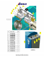
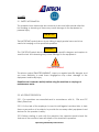
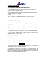
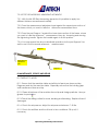
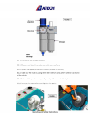
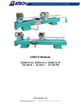
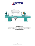
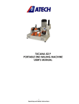
ZETA-02 A
AUTOMATIC DOUBLE GLAZING BEAD SAW
User's Manual
1
Operating and Safety Instructions
1. GENERAL INFORMATION
1.1. INTRODUCTION
The user’s manual given by the manufacturer contains necessary
information about the machine parts. Each machine operator should
read these instructions carefully, and the machine should be operated
after fully understanding them.
Safe and efficient use of the machine for long term depends on
understanding and following the instructions contained in this manual.
The technical drawings and details contained in this manual constitute a
guide for the operator.
1.2. DISTRIBUTOR
ATech Machine, Inc.
10752-A Tucker Street – Beltsville, MD 20705 USA
Phone: +1-301-595-1816 Fax: +1-301-560-6627
Website: www.ATechMachinery.com
E-mail: [email protected]
In case of any technical problem please contact your nearest
ATECH dealer, or ATECH head office through the above mentioned
phone, fax or e-mail address.
Technical labels with the model description of the machine are
fixed onto the front side of each machine.
The machine’s serial number and manufacturing year are stipulated on
the technical label.
2
Operating and Safety Instructions
CONTENTS
1. General information
1.1. Introduction
1.2.
2. Machine’s description and purpose of use
2.1. Machine’s definition
2.2. Technical features
2.3. Dimensions
2.4. General views
3. Safety
3.1. Safety information
3.2. Accident prevention
3.3. General safety information
4. Transport of the Machine
5. Installation of the Machine
5.1. Preperation
5.2. Electric connection
6. Machine Safety Information
7. Operation
7.1. Cutting operation
7.2. Use of the KA 200 Easy measuring apparatus
8. Maintenance, Service and Repair
8.1. Starting to Work
8.2. Air Pressure Adjustments
8.3. Changing the cutter group
8.4. Maintenance at the End of Working Day
9. Troubleshooting guide
3
Operating and Safety Instructions
1.GENERAL INFORMATION
1.1. INTRODUCTION
The user’s manual given by the manufacturer contains necessary information
about the machine parts.Each machine operator should read these instructions
carefully, and the machine should be operated after fully understanding them.
Safe and efficient use of the machine for long term depends on understanding
and following the instructions contained in this manual.The technical drawings
and details contained in this manual
constitute a guide for the operator.
2. MACHINE’S DESCRIPTION AND PURPOSE OF USE
2.1. MACHINE’S DESCRIPTION
Cutting of PVC double glazing beads at 45° angle.
Clamping system is pneumatic, while cutting is automatic.
Cutting speed is adjustable.
After finishing the cutting operation the saw blades return to their original
position automatically.
The machine has been designed according to UL, CSA and CE Safety
Directives.
STANDARD ACCESSORIES
OPTIONAL ACCESSORIES
KN 152 Conveyor
KA 200 Easy measuring apparatu
Air gun
User’s Manual
Ø200 Saw Blade
Ø110 Saw Blade
Screw wrench (for changing mold)
KN 152 Conveyor (Extra)
2.2. TECHNICAL FEATURES
4
Operating and Safety Instructions
2.3 DIMENSIONS
200 cm
110 cm
105 cm
46 cm
FIGURE 1
5
Operating and Safety Instructions
2.4 GENERAL VIEWS
FIGURE 2
6
Operating and Safety Instructions
FIGURE 3
FIGURE 4
7
Operating and Safety Instructions
3. SAFETY
3.1. SAFETY INFORMATION
The symbols shown hereunder are necessary to be read with special attention.
Not reading or observing of them may cause damage to the equipment or
personal injury.
IMPORTANT
The IMPORTANT symbol above is one telling to apply special care and to be
careful at carrying out the specified operation
CAUTION !
The CAUTION! Symbol above warns you against specific dangers, and requires to
read the text. Not observing may cause damage to the equipment..
DANGER WARNING
The above symbol DANGER WARNING, warns you against specific dangers, and
you have definitely to read them. Negligence may cause damage to the
equipment and bodily injury.
Read the user’s manual carefully before using the machine or carrying out
maintenance works.
3.2. ACCIDENT PREVENTION
3.2.1. Our machines are manufactured in accordance with UL, CSA and CE
Safety Directives.
3.2.2. It is the task of the employer to warn his staff against accident risks, to train
them on prevention of accidents, to provide for necessary safety equipment and
devices for the operator’s safety.
3.2.3. Before starting to work with the machine, the operator should check the
features of the machine, learn all details of the machine's operation.
8
Operating and Safety Instructions
3.2.4. Machine should be operated only by staff members, who have read and
understood the contents of this manual.
3.2.5. All directives, recommendations and general safety rules contained in this
manual have to be observed fully. The machine cannot be operated in any way
for purposes other than those described herein.
Otherwise, the manufacturer shall not be deemed responsible for any damages
or injuries. And such circumstances would lead to the termination of the
warranty.
3.3. GENERAL SAFETY INFORMATION
3.3.1. The power cable should be led in such a way that nobody can step on it or
nothing can be placed on it. Special care
has to be taken regarding the inlet and
outlet sockets.
3.3.2. If the power cable should be damaged during operation, don't touch and
unplug it. Never use damaged power cables.
3.3.3. Don’t overload machines for drilling and cutting. Your machine will
operate more safely with power supply in accordance with the stipulated
values.
3.3.4. Don’t place your hands between parts in motion.
3.3.5. Use protective eye glasses and ear plugs. Don't wear oversize clothes
and jewels. These can be caught by moving parts.
3.3.6. Keep your working place always clean, dry and tidy for accident
prevention and safe operation.
9
Operating and Safety Instructions
3.3.7. Use correct illumination for the safety of the operator. ( ISO 8995-89
Standard The lighting of indoor work system )
3.3.8. Don't leave anything on the machine.
3.3.9. Don’t use any materials other than those recommended by the
manufacturer for cutting
operations on the machine.
3.3.10. Ensure that the work piece is clamped appropriately by the machine's
clamp or vice.
3.3.11. Ensure safe working position, always keep your balance.
3.3.12. Keep your machine always clean for safe operation. Follow the
instructions at maintenance and replacement of accessories. Check the plug
and cable regularly. If damaged, let it replace by a qualified electrician. Keep
handles and grips free of any oil and grease.
3.3.13. Unplug first, before conducting and maintenance works.
3.3.14. Ensure that any keys or adjustment tools have been removed before
operating the machine.
3.3.15. If you are required to operate the machine outside, use only appropriate
extension cables.
3.3.16. Repairs should be carried out by qualified technicians only. Otherwise,
accidents may occur.
3.3.17. Before starting a new operation, check the appropriate function of
protective devices and tools, ensure that they work properly. All conditions have
to be fulfilled in order to ensure proper operation of your machine. Damaged
protective parts and equipment have to be replaced or repaired properly (by
the manufacturer or dealer).
3.3.18. Don’t use machines with improper functioning buttons and switches.
3.3.19. Don’t keep flammable, combustive liquids and materials next to the
machine and electric
connections.
IMPORTANT
10
Operating and Safety Instructions
4. TRANSPORT OF THE MACHINE
* The transport should be done by qualified personnel only.
4.1. The machine should be transported by lifting with proper equipment (not
touching the ground during the transport).
4.2. The Machine is delivered wrapped in nylon as packaging, unless other form
of packing is agreed upon with the
customer.
4.3. For the weight and overall dimensions of the machine see Page 32.
5. INSTALLATION OF THE MACHINE
Necessary air and electrical facilities should be organized by the customer.
5.1. PREPERATION
5.1.1. The machine's dimension are shown in the Technical Features page (Page
33). The ground, where the machine will be placed, should be even, solid
enough to bear the weight of the machine.
5.1.2. The machine should be located approx. 50 cm away from the back wall.
5.1.3. As a conveyor will be installed to its lateral surface, you should leave a
distance equal to the conveyor length
5.2. ELECTRIC CONNECTION
5.2.1 The three-phase electric cable socket has to be in accordance with the
socket on the machine.
5.2.2 The operating voltage is 400V 50 Hz. Check the supply voltage.
5.2.3 Use grounded sockets.
IMPORTANT !
5.2.4. Check the supply voltage. The supply voltage must be in accordance with
the data stipulated on the machine’s type label.
5.2.5. The electric connections have to be made by a qualified electrician, the
rotation direction of the milling cutters has to be observed by starting the
machine. If the milling cutters rotate in reverse direction, the socket connections
have to be checked and re-connected properly.
11
Operating and Safety Instructions
5.2.6. If the cutters rotate in reverse direction, it will cause danger for the
operator and the equipment.
6. MACHINE SAFETY INFORMATION
6.1. It is not allowed to operate the machine with the protective cover and other
protective equipment removed.
6.2. Lifting, installation, electric, pneumatic maintenance of the machine should
be carried out by qualified personnel only.
6.3. Routine maintenance and scheduled maintenance should be carried out by
qualified personnel after unplugging the machine and disconnecting the air
supply first.
6.4. Ensure that the machine has been cleaned, tested and maintained before
starting to operate.
6.5. Check the safety devices, power cable and moving parts regularly.Don’t
operate the machine before having replaced defective safety devices or faulty
parts.
6.6. Never replace the milling cutters before unplugging first.
6.7. Keep foreign materials away from the working area of the machine, keep
away from the machine’s moving parts.
IMPORTANT
The safety data have been defined above. In order to prevent physical damage
or damage to the equipment, please read the safety information carefully and
keep the manual always in an easy accessible place.
12
Operating and Safety Instructions
7. OPERATION
7.1. CUTTING OPERATION
7.1.1. Clean the glazing bead mould channels from any burr and foreign
materials. Ensure especially that the glazing bead molds are clean.
7.1.2. Clean all surfaces of the machine from chip and foreign particles. Use eye
glasses for protection.
7.1.3. Check with the appropriate keys that the milling cutters are tightened well.
7.1.4. Check the milling cutters for wear, bending and breaking. Replace them if
damaged.
7.1.5. The CK 410 Automatic Glazing Bead Saw has been designed for cutting of
aluminum and PVC glazing beads at 45° angle for making 90° corner joining.
7.1.6. Connect the air hose with appropriate inner diameter to the air inlet
sleeve. (See FIGURE 5)
7.1.7. Switch the system start switch to “1” (FIGURE 4 – No.18)
7.1.8. Place the profile on the lath mould. Adjust the cutting length of the bead
using the measuring tape and bead support plate.(FIGURE 2-No.6)
7.1.9. Start the electrical motor by pressing the motor start button. (FIGURE4 –
NO.19)
7.1.10. Begin the cutting operation by pressing the cutting start button. The
machine automatically performs cutting operation and returns back to its
starting position. Stop the electirical motor by pressing the motor stop button.
(FIGURE4 – NO:19)
7.1.11. To change the factory setted value of cutting feed, use the adjusting
throttle in the electrica panel. (FIGURE2 – NO.3)
7.1.12. Up-Down adjustment of glazing bead mould can be performed by
adjustment part on the machine. (FIGURE2 – NO.3). First loosen the set square
fixing set screws (FIGURE2 – NO.15). Make the adjustment by turning the knob
up/down. Then again tighten the set screws and nut.
7.1.13. Use emergency button (FIGURE4 – NO.20) by pressing in case of any
irregularities.
13
Operating and Safety Instructions
7.2. USE OF THE KA 200 EASY MEASURING APPARATUS
7.2.1. With the KA 200 Easy Measuring apparatus it is possible to apply two
different distance measurements serially.
7.2.2. Press the measurement adjustment part against the upper inner section of
the frame, which you want to take the reference measurement from
7.2.3. Press the part Support 1 against the lower inner section of the frame, where
you want to take the reference measurement from, by loosening and moving
the tightening handle. Tighten the handle again to fix the position.
7.2.4. You may repeat the above described operation for the part Support 2 as
well to use it for the second reference measurement.
Support 1
Measurement
adjustment
part
Support 2
8. MAINTENANCE, SERVICE AND REPAIR
8.1 STARTING TO WORK
8.1.1. Ensure that the machine table and all kind of parts are clean and dry.
Degrease and dry the machine table. Especially ensure that the holding grips
and handles are clean and dry.
8.1.2. Clean all surfaces of the machine from chip and foreign particles. Use eye
glasses for protection.
8.1.3 Check the milling cutters for wear, bending and breaking. Replace them if
damaged.
8.1.4. Check the air pressure. Adjust the air pressure between 7 – 8 Bar
8.1.5. Check the air filters and the oil level in the conditioner. Fill up oil, if
necessary
14
Operating and Safety Instructions
Always disconnect the electric and power supply first before carrying out these
works.
If the machine is not active because of maintenance or service, put a warning
message that can be easily seen, indicating the situation
8.2. AIR PRESSURE ADJUSTMENT
8.2.1. Pull the adjustment button of the conditioner upwards
8.2.2. Turning the adjustment button in clockwise direction increases the
pressure.
8.2.3. Turning the adjustment button in counter clockwise direction decreases
the pressure.
8.2.4. Once you read 6-8 Bar on the manometer, push the adjustment button of
the conditioner down and lock it in that position.
8.2.5. To make up the lessen oil level in the oil tank, take out the oil depot by
turning. And re-fasten the oil depot after make up.
8.2.6. The manufacturer recommends to use the following oils with the
conditioner: TELLLUS C 10 / BP ENERGOL HLP 10/ MOBIL DTE LIGHT / PETROL
OFISI SPINDURA 10.
8.2.7. To discharge the accumulated water in the lubricator, loosen the water
discharge nut.
8.2.8
Adjust the lubricator working level to once for 10 cycles.
15
Operating and Safety Instructions
16
Operating and Safety Instructions
NOTE: ENSURE THAT THE SAW BLADES ROTATE IN CORRECT DIRECTION (THE
CORRECT DIRECTION HAS BEEN MARKED ON THE MACHINE'S UPPER COVER)
8.4. MAINTENANCE AT THE END OF THE WORKING DAY
8.4.1. Disconnect the electric and power supply. (Main Switch in “0” position)
8.4.2. Remove all burr and foreign materials from the machine. If it is necessary
to clean the inside of the protection cover, lift and clean it wearing
protective gloves because of the cutters. Use protective eye glasses.
8.4.3. If you have used water or water based liquids during drilling operations,
dry the machine with a dry cloth after the operation is finished.
8.4.4. If the machine will not be used for a long time, lubricate the unpainted
sections of the machine as protection against corrosion.
8.4.5. Avoid damage to the paint when cleaning the machine.
8.4.6. Apply protective machine oil onto both surfaces of the milling cutters as
protection against corrosion.
9. INFORMATION ABOUT FAULTY USE
9.1. Check the plug for power supply.
9.2. Ensure that the rotation direction of the milling cutters is correct. (the correct
direction is marked on the upper cover).
9.3. Don’t use too high cutting speeds. Adjust the cutting speed with the reducer
valve
9.4. Never operate the machine with the protection covers open.
17
Operating and Safety Instructions