1
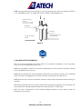
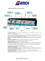
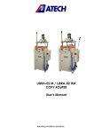
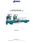
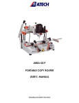
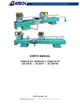
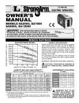
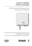
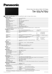
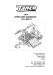
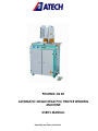
PHOENIX-02 SH
AUTOMATIC SINGLE HEAD PVC PROFILE WELDING
MACHINE
USER’S MANUAL
1
Operating and Safety Instructions
CONTENTS
Page
1. General Information
1.1. Introduction
1.2. Manufacturer
2. Machine’s Description and Purpose of Use
2.1. Machine’s description
2.2. Technical features
2.3. Overall dimensions
2.4. Part list and technical drawings
3. Safety
3.1. Safety information
3.2. Accident prevention
3.3. General safety information
4. Transport of the Machine
5. Installation of the Machine
5.1. Preparation
5.2. Electric connection
5.3. Air pressure adjustment
6. Machine Safety Information
7. Operation
7.1. General
7.2. Buttons and displays on the machine
7.3. Welding operation
8. Maintenance
8.1. Periodic checks
8.2. Replacing and cleaning of the Teflon cover
8.3. Maintenance at the end of working day
9. Troubleshooting Guide
10. Electric and Pneumatic Components
10.1. Electric components
10.2. Pneumatic components
2
Operating and Safety Instructions
3
3
3
3
3
5
6
7
10
10
10
11
13
13
13
13
13
14
15
15
16
17
17
17
18
18
18
19
19
19
1. GENERAL INFORMATION
1.1. INTRODUCTION
The user’s manual given by the manufacturer contains necessary information about the
machine parts. Each machine operator should read these instructions carefully, and the
machine should be operated after fully understanding them.
Safe and efficient use of the machine for long term depends on understanding and
following the instructions contained in this manual. The technical drawings and details
contained in this manual constitute a guide for the operator.
1.2 DISTRIBUTOR
ATech Machine, Inc.
10752-A Tucker Street – Beltsville, MD 20705 USA
Phone: +1-301-595-1816 Fax: +1-301-560-6627
Website: www.ATechMachinery.com
E-mail: [email protected]
In case of any technical problem please contact your nearest ATECH dealer, or ATECH
head office through the above mentioned phone fax or e-mail address.
Technical labels with the model description of the machine are fixed onto the front side of
each machine.
The machine’s serial number and manufacturing year are stipulated on the technical
label.
2. MACHINE’S DESCRIPTION AND PURPOSE OF USE
2.1 MACHINE’S DESCRIPTION
Machine is designed for the joining of vinyl (PVC) profiles though corner welding.
Capable of adjusting the clamp and welding pressure according to the profile type.
Equipped with a timer for melting and welding time. Capable of welding at angels
between 300 – 1800 Profiles are clamped one by one via foot pedal.
After clamping the profiles, the welding is carried out automatically.
The thermostat is electronic and can be adjusted in a temperature range between
00-2600 C.
3
Operating and Safety Instructions
Please mention the below mentioned data in all your correspondence regarding the
machine with the manufacturer and/or your ATECH dealer.
*Machine model
*Machine’s serial number
*Voltage and frequency
*Name of dealer where machine was purchased
*Date of purchase
*Description of the machine fault
*Average daily operation period
4
Operating and Safety Instructions
2.2 TECHNICAL FEATURES
Technical
Features
(American)
PHOENIX-02 SH
1.5kW
120V 60Hz
Max.h:5 "
α=30°-180°
1,5kW
230V 50Hz
Max.h:130 mm.
α=30° - 180°
90-120 psi
1,25 CFM
31x34x55"
506 lb
Technical
Features (Metric)
PHOENIX-02 SH
6-8 Bar
5
Operating and Safety Instructions
35l/min
78x85x140 mm
230 kg
2.3 OVERALL DIMENSIONS
6
Operating and Safety Instructions
2.4 PART LISTS AND TECHNICAL DRAWINGS
Figure-1
NO
2
3
4
6
12
13
30
42
44
51
55
57
58
STOCK
CODE
143-126
141-234
145-035
111-156
242-005
112-080
147-001
191-003
550-025
111-158
242-022
111-161
143-027
61
63
64
66
67
68
71
212-002
242-019
242-018
145-033
141-232
111-155
141-050
73
75
211-018
550-010
PART NAME
PISTON HOUSING SHAFT
CLAMP SHOE
LEFT TABLE
CLAMP COLUMN
PISTON PAG Y 80x90
LEFT SET SQUARE
SUPPORT PROFILE
6201 BEARING
PIN CYLINDER
RESISTANCE PLATE
PISTON PMY 50x25
HEATING PLATE HOUSING
HEATING PLATE HOUSING
SHAFT
FRAME
PISTON PMY 40x170
PISTON PMY 32x50
GUIDE PLATE
FORK SHAFT
GUIDE BEARING HOUSING
M16x55 FOOT ADJUSTMENT
BOLT
PANEL
HANDLE
7
Operating and Safety Instructions
QTY
4
2
1
2
2
2
2
1
2
1
1
1
2
1
1
1
1
1
1
2
1
2
Figure-2
8
Operating and Safety Instructions
NO.
PART NAME
1
STOCK
CODE
145-039
QTY
NO.
TABLE ADJUSTM. DOWEL
2
59
STOCK
CODE
145-037
2
3
4
6
7
8
9
12
13
15
18
143-026
141-234
145-035
111-156
111-162
111-159
143-028
242-005
112-080
145-035
141-243
PISTON HOUSING SHAFT
CLAMP SHOE
LEFT TABLE
CLAMP COLUMN
TABLE SHAFT HOUSING
TABLE SHAFT HOUSING
TABLE HOUSING SHAFT
PISTON PAG Y 80x90
LEFT SET SQUARE
RIGHT TABLE
TABLE SHAFT HOUSING
WASHER
TEFLON WASHER
6201 BEARING
PIN CYLINDER
PISTON CONNECTION
MOVEMENT HOUSING
RESISTANCE PLATE
TABLE PISTON CONNECT.
PISTON PMY 50x25
HEATING PLATE HOUSING
HEATING PLATE HOUSING
SHAFT
4
2
1
2
4
2
2
2
2
1
2
63
64
65
66
67
68
70
242-019
242-018
145-034
145-033
141-232
111-155
176-004
19
43
44
45
48
51
54
55
57
58
142-034
191-003
550-025
111-157
111-154
111-158
111-160
242-022
111-161
143-027
4
2
2
2
1
1
1
1
1
2
9
Operating and Safety Instructions
PART NAME
HEATING PLATE HOUSING
CONNECT. PLATE
PISTON PMY 40x170
PISTON PMY 32x50
GUIDE PISTON PLATE
GUIDE PLATE
FORK SHAFT
GUIDE BEARING HOUSING
M12 BOLT
QTY
1
1
1
1
1
1
1
1
3. SAFETY
3.1. SAFETY INFORMATION
The symbols shown hereunder are necessary to be read with special attention.
Not reading or observing of them may cause damage to the equipment or personal injury
IMPORTANT
The IMPORTANT symbol above is one telling to apply special care and to be careful at
carrying out the specified operation.
CAUTION !
The CAUTION! Symbol above warns you against specific dangers, and requires to read the
text. Not observing may cause damage to the equipment.
DANGER WARNING
The DANGER WARNING above warns you against specific dangers, and definitely requires
the text to read. Not observing may result in serious bodily injury.
Please read the user’s manual carefully before using the machine or carrying out
maintenance.
3.2. PREVENTION OF ACCIDENTS
3.2.1 Our machines are manufactured in accordance with EN 60204-1 and EN 292-2 CE
safety directives, which cover national and international safety directives.
3.2.2 It is the task of the employer to warn his staff against accident risks, to train them on
prevention of accidents, to provide for necessary safety equipment and devices for the
operator’s safety.
3.2.3 Before starting to work with the machine, the operator should check the features of
the machine, learn all details of the machine's operation.
10
Operating and Safety Instructions
3.2.4 The machine should be operated only by staff members, who have read and
understood the contents of this manual.
3.2.5 All directives, recommendations and general safety rules contained in this manual
have to be observed fully. The machine cannot be operated in any way for purposes
other than those described herein. Otherwise, the manufacturer shall not be deemed
responsible for any damages or injuries. And such circumstances would lead to the
termination of the warranty.
3.3. GENERAL SAFETY INFORMATION
3.3.1. The power cable should be led in such a way that nobody can step on it or
nothing can be placed on it. Special care has to be taken regarding the inlet and
outlet sockets.
3.3.2. If the power cable should be damaged during operation, don't touch and
unplug it. Never use damaged power cables.
3.3.3. Don’t overload machines for drilling and cutting. Your machine will operate
more safely with power supply in accordance with the stipulated values.
3.3.4. Don’t place your hands between parts in motion.
3.3.5. Use protective eye glasses and ear plugs. Don't wear oversize clothes and
jewels. These can be caught by moving parts.
3.3.6. Keep your working place always clean, dry and tidy for accident prevention
and safe operation.
3.3.7. Use correct illumination for the safety of the operator. (ISO 8995-89 The Lighting
of Indoor Work Systems)
11
Operating and Safety Instructions
3.3.8. Don't leave anything on the machine.
3.3.9. Don’t use any materials other than those recommended by the manufacturer
for cutting operations on the machine.
3.3.10. Ensure that the work piece is clamped appropriately by the machine's clamp
or vice.
3.3.11. Ensure safe working position, always keep your balance.
3.3.12. Keep your machine always clean for safe operation. Follow the instructions at
maintenance and replacement of accessories. Check the plug and cable regularly.
If damaged, let it replace by a qualified electrician. Keep handles and grips free of
any oil and grease.
3.3.13. Unplug first, before conducting and maintenance works.
3.3.14. Ensure that any keys or adjustment tools have been removed before
operating the machine.
3.3.15. If you are required to operate the machine outside, use only appropriate
extension cables.
3.3.16. Repairs should be carried out by qualified technicians only. Otherwise,
accidents may occur.
3.3.17. Before starting a new operation, check the appropriate function of
protective devices and tools, ensure that they work properly. All conditions have to
be fulfilled in order to ensure proper operation of your machine. Damaged
protective parts and equipment have to be replaced or repaired properly (by the
manufacturer or dealer).
3.3.18. Don’t use machines with improper functioning buttons and switches.
3.3.19. Don’t keep flammable, combustive liquids and materials next to the machine and
electric connections.
12
Operating and Safety Instructions
4. SAFE TRANSPORT OF THE MACHINE
IMPORTANT
* The transport should be done by qualified personnel only.
4.1. The machine should be transported by lifting with proper equipment (not touching the
ground during the transport).
4.2. The Machine is delivered wrapped in nylon as packaging, unless other form of
packing is agreed upon with the customer.
4.3. For the weight and overall dimensions of the machine see Technical Features.
5. INSTALLATION OF THE MACHINE
The machine should be located at least 50 cm in front of the back wall. The machine is
equipped with a burr collection bag connector and power supply socket on the back
side.
5.1. PREPARATION
IMPORTANT
Remove the bolts and stopper connections first, which are used to fix the moving parts,
before making the electric and pneumatic connections, and starting the machine.
5.2. ELECTRIC CONNECTON
5.2.1 The electric connections have to be carried out by a qualified electrician. Use only
cables in accordance with the CE Directives.
5.2.2. Check the inlet power before plugging the machine in.
5.3. AIR PRESSURE ADJUSTMENT
The air pressure of the machine has to be between 6-8 Bar for proper functioning of the
pneumatic system. Don’t operate the machine with an air pressure lower than 6 Bar. To
adjust and to check the air pressure, read the manometer on the conditioner (See Figure
3).
5.3.1 Pull the adjustment button of the conditioner upwards.
5.3.2 Turning the adjustment button in clockwise direction increases the pressure ,turning it
in counter clockwise direction decreases the pressure.
5.3.3 Once you read 6-8 Bar on the manometer, push the adjustment button of the
conditioner down and lock it in that position.
5.3.4 The conditioner unit collects the water within the air system in a receptacle in order
to prevent damage to the pneumatic system components. Discharge this water
periodically (at the end of the working day) by pressing or opening the button under the
conditioner.
13
Operating and Safety Instructions
5.3.5 The manufacturer recommends to use the following oils with the conditioner: TELLUS
C 10 / BP ENERGOL HLP 10/ MOBIL DTE LIGHT / PETROL OFISI SPINDURA 10.
PRESSURE ADJUST.
BUTTON
MANOMETER
OIL DEPOT
OPEN THE OIL FILLING
CAP FROM HERE
WATER DISCHARGE
SCREW
Figure-3
6. MACHINE SAFETY INFORMATION
6.1 Your machine operates with 230V 50Hz. Let the electric installation of your machine
carry out by a qualified electrician only.
6.2 Lifting, installation, electric, pneumatic maintenance of the machine should be carried
out by qualified personnel only.
6.3 Routine maintenance and scheduled maintenance should be carried out by qualified
personnel after unplugging the machine and disconnecting the air supply first.
6.4 Ensure that the machine has been cleaned, tested and maintained before starting to
operate.
6.5 Check the safety devices, power cable and moving parts regularly. Don’t operate the
machine before having replaced defective safety devices or faulty parts.
6.6 If you wish to terminate the PVC profile welding operation for any reason, press the
Emergency Stop button.
14
Operating and Safety Instructions
6.7 Keep foreign materials away from the working area of the machine, keep away from
the machine’s moving parts.
6.8 As the machine is equipped with foot pedal, you do not need your hands during the
welding operation. Keep away from the pistons during the operation.
IMPORTANT
The safety data have been defined above. In order to prevent physical damage or
damage to the equipment, please read the safety information carefully and keep the
manual always in an easy accessible place.
7. OPERATION
7.1 GENERAL
The PHOENIX-I Automatic Vinyl (PVC) Single Corner Welding Machine has been designed
for the corner joining of PVC profiles. Do not use the machine for any other purposes.
15
Operating and Safety Instructions
7.2 BUTTONS AND DISPLAYS ON THE MACHINE
Clamp Pressure
Display
Maintenance
Button
Temperature
Display
Welding Pressure
Display
Welding
Pressure
Adjustment
Heating Time
Adjustment
Clamp
Pressure
Adjustment
System
Start
Emergency
Stop
Welding Time
Adjustment
ayarı
Figure-4
Temperature Display: For adjusting the temperature of the resistance, which heats and
welds PVC profiles, between
0 - 260 C. The temperature is pre-set to 245 C at the factory. To change this value, press
“Set”. The pre-set value will blink. Input the new temperature value using the arrows on the
display. Press “Set” again to save the input value.
Caution: Do not touch the (PRG) button next to the Set button. It has been pre-set in the
factory.
Emergency Stop Button: When the Emergency Stop button is pressed, all pneumatic
electric components of the machine return to their original position.
System Start Button: Used to start the welding operation.
Welding Pressure Adjustment: For adjusting the welding pressure of profiles to be joined via
heating and welding. It is pre-set to 6 Bar in the factory. If you want to change this value,
turn the switch to the right or left respectively to increase or decrease it. To lock the set
value, press the outer frame of the switch down.
Welding Pressure Display: It reads the welding pressure force in Bar.
Clamp Pressure Adjustment: It adjusts the pressure force of the clamps, which clamp the
PVC profiles to be welded. It is pre-set to 4 Bar. This adjustment is made in the same way
like the welding pressure adjustment.
Clamp Pressure Display: It reads the pressure force of the PVC profiles clamp in Bar.
Heating Time Display: Adjusts the time for application of the set temperature. It can be
adjusted between 0-30 sec. It is pre-set to 20 sec.
16
Operating and Safety Instructions
Welding Time Display: To adjust the welding time of PVC profiles. This period can be
adjusted between 0 - 30 sec. It is pre-set to 25 sec.
Maintenance Button: Used for cleaning and changing the Teflon cover of the heating
plate. It moves up the heating plate and keep it in that position to clean or to change the
Teflon cover. The Teflon cover is cleaned with a dry cloth.
Foot Pedal: When the foot pedal is pre4ssed once, the guide fence moves down. The PVC
profile is placed on the right table and pressed against this guide fence. After pressing the
foot pedal the second time, the clamp piston over the right table moves down and
clamps the profile. After pressing the foot pedal the third time, the clamp piston over the
left table moves down and clamps the profile on the left table.
7.3 WELDING OPERATION
7.3.1. Ensure that the machine’s electric and pneumatic connections have been made
correctly.
7.3.2. Press the System Start button (Figure 4).
7.3.3. Place the first PVC profile onto the right table (Figure 2, No. 15). Press the foot pedal
once, whereupon the guide plate (fence) moves down (Figure 1, No. 66).
7.3.4. Press the profile end against the guide plate. Press the foot pedal again, whereupon
the profile will be clamped.
7.3.5. Place the second profile on the left table (Figure 2, No. 4) and press it against the
other side of the guide plate. Press the foot pedal again to clamp the profile via clamp
piston. The remaining operation will be carried out automatically within the adjusted
temperature and time period.
NOTE: Never place your hands under the pistons during the welding operation.
8. MAINTENANCE
8.1. PERIODIC CHECKS
8.1.1 Ensure that the table and all parts are clean and dry. Degrease the table and dry it.
8.1.2 Clean the machine surface.
8.1.3 Check the pressure of the air pressure system.
8.1.4 Check the air pressure filter and the oil level of the conditioner. Fill up oil, if necessary
(Figure 3).
17
Operating and Safety Instructions
8.2. CLEANING AND REPLACING THE HEATING PLATE TEFLON COVER
8.2.1 To clean the Teflon cover, press the Maintenance button (Figure 4). The heating
plate (Figure 1, No. 51) will move upwards.
8.2.2 Clean the Teflon with a dry cloth.
8.2.3 To replace the Teflon cover, remove the thin plates on both sides of the heating
plate with a proper key.
8.2.4 Replace the old Teflon with a new one and fix it by tightening the thin plates.
8.3. MAINTENANCE AT THE END OF WORKING DAY
8.3.1 Disconnect the electric and air supply to the machine.
8.3.2 Clean the machine surface and remove all foreign materials.
8.3.3 After cleaning the table, dry it with a cloth (don’t use aggressive substances for
cleaning, which could damage the paint).
Unplug and disconnect the air pressure connections first, before carrying out these works.
9. TROUBLESHOOTING GUIDE
TROUBLES
The resistance does not heat
The thermocouple does not work
CAUSES
REMEDY
No power supply to the machine
Check the fuse, plug and socket.
The thermocouple connection wire is
Connect the thermocouple wire.
displaced.
The temperature display needs to be
set.
Check the temperature display adjustment
(245˚)
The heating plate does not move. The air pressure is too low.
Check the air hose connections of the
machine.
Adjust the air pressure at the conditioner.
Machine does not weld or the The profiles were cut in different Check the angles of the profile ends.
welding is not clean.
angles.
The saw blade might need to be sharpened.
The Teflon is dirty or torn.
The Teflon should be cleaned or replaced.
If these recommendations do not solve the trouble, please ask for technical service.
18
Operating and Safety Instructions
10. ELECTRIC AND PNEUMATIC COMPONENTS
10.1 ELECTRIC COMPONENTS
161-011
164-010
164-015
164-017
164-018
165-005
165-038
165-045
165-049
165-058
165-100
RESISTANCE
3*1 TTR CABLE
PRINTED PLUG 3*1
SILICON CABLE 2.5mm RED
SILICON CABLE 2.5mm YELLOW-GREEN
UY3010 (1 mm) CABLE THUMB
PORCELAIN CONNECTOR
NO:2 PANEL SPIRAL (THICK)
GROUNDING SHOE
SINGLE-PHASE PLUG
STEEL SPIRAL (11mm)
1
3
1
1.7
3.4
3
1
1
1
1
0.5
10.2 PNEUMATIC COMPONENTS
242-005
242-008
242-010
242-011
242-018
242-019
242-022
242-031
244-011
PISTON PAG AY 80*90
PISTON FORK 32*50
PISTON EB 50
PISTON EYB 32*50
PISTON PMY 32*50
PISTON PMY 40*170
PISTON PMY 50*25
SHAFT END BOLT 50 mm
O-RING 28*2
19
Operating and Safety Instructions
2
1
1
1
1
1
1
1
4