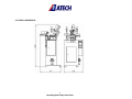
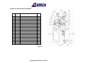
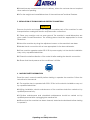
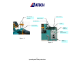
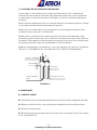
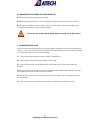
1
DOLPHIN-02 A
AUTOMATIC PVC WATER SLOT MILLING MACHINE
USER’S MANUAL
1
Operating and Safety Instructions
CONTENTS
Page
1. General Information
3
1.1. Introduction
3
1.2. Manufacturer
3
2. Machine’s Description and Purpose of Use
3
2.1. Machine’s description
3
2.2. Technical features
5
2.3. Overall dimensions
6
2.4. Part lists and technical drawings
7
3. Safety
8
3.1. Safety information
8
3.2. Accident prevention
8
3.3. General safety information
9
4. Transport of the Machine
10
5. Installation of the Machine and Electric Connection
11
6. Machine Safety Information
11
7. Operation
14
7.1. Changing the router bit
14
7.2. Adjusting the machine’s air pressure
15
8. Maintenance
15
8.1. Periodic checks
15
8.2. Maintenance at the end of working day
16
9. Troubleshooting Guide
16
10. Electric / Pneumatic Components
17
10.1. Electric Components
17
10.2. Pneumatic Components
17
2
Operating and Safety Instructions
1. GENERAL INFORMATION
1.1. INTRODUCTION
The user’s manual given by the manufacturer contains necessary information about the
machine parts. Each machine operator should read these instructions carefully, and the
machine should be operated after fully understanding them.
Safe and efficient use of the machine for long term depends on understanding and
following the instructions contained in this manual. The technical drawings and details
contained in this manual constitute a guide for the operator.
1.2. DISTRIBUTOR
ATech Machine, Inc.
10752-A Tucker Street – Beltsville, MD 20705 - USA
Phone: +1-301-595-1816 Fax: +1-301-560-6627
Website: www.ATechMachinery.com
E-mail: [email protected]
In case of any technical problem please contact your nearest ATECH dealer, or ATECH
head office through the above mentioned phone fax or e-mail address.
Technical labels with the model description of the machine are fixed onto the front side
of each machine.
The machine’s serial number and manufacturing year are stipulated on the technical
label.
2. MACHINE’S DESCRIPTION AND TECHNICAL FEATURES
2.1. MACHINE’S DESCRIPTION
This machine has been designed for milling of water discharge slots onto PVC profiles on
two or three axes, in different angles and heights.
It automatically adjusts axis deviations.
Automatic operation via single button.
Motor selection via buttons. Model DOLPHIN-02 A is equipped with 3
motors.
Please mention the below mentioned data in all your correspondence regarding the
machine with the manufacturer and/or your ATECH dealer.
3
Operating and Safety Instructions
*Machine model
*Machine’s serial number
*Voltage and frequency
*Name of dealer where machine was purchased
*Date of purchase
*Description of the machine fault
*Average daily operation period
4
Operating and Safety Instructions
2.2 TECHNICAL FEATURES
Technical
Features
(American)
DOLPHIN-02 A
With 2 Drills
600W X 2
120V 60Hz
27000 rpm
90-120 psi
1 CFM
20x20x54"
139 lb
DOLPHIN-02 A
With 3 Drills
600W X 3
120V 60Hz
27000 rpm
90-120 psi
1 CFM
20x20x54"
145 lb
Technical
Features
(Metric)
DOLPHIN-02 A
With 2 Drills
600W X 2
230V 50Hz
27000 rpm
6-8 Bar
27 1/min
50x51x138 cm
63 kg
DOLPHIN-02 A
With 3 Drills
600W
230V 50Hz
27000 r.p.m
6-8 Bar
27 1/min
50x51x138 cm
66 kg
5
Operating and Safety Instructions
2.3 OVERALL DIMENSIONS
6
Operating and Safety Instructions
2.4 PART LISTS AND TECHNICAL DRAWINGS
NO
STOCK
PART NAME
QTY
9
10
11
12
13
14
15
17
18
21
23
26
28
33
35
40
42
43
48
49
CODE
111-149
111-152
111-150
143-019
141-141
241-009
145-032
211-017
111-147
111-151
163-003
143-021
143-023
141-221
550-003
550-023
550-024
143-017
211-017
141-219
MOTOR MOVEMENT BAD
TABLE HOUSING
TABLE
AXIS MOVEMENT SHAFT
FOOT ADJUSTMENT BOLT
CONDITIONER
UPPER CONNECTION ROD
FRAME
FRAME BASE
LATERAL CONNECTION
MOTOR
1.MOTOR HOUSING SHAFT (LEFT)
2.MOTOR HOUSING SHAFT (RIGHT)
CLAMP COLUMN SHAFT
PNEUMATIC CLAMP
AXIS POSITIONING PISTON
2.MOTOR PISTON
2.MOTOR PISTON SHAFT
PANEL
MOTOR ADJUSTMENT BOLT
3
2
1
4
2
1
2
1
2
2
3
1
1
2
2
2
2
2
1
2
Figure - 1
7
Operating and Safety Instructions
3. SAFETY
3.1. SAFETY INFORMATION
The symbols shown hereunder are necessary to be read with special attention.
Not reading or observing of them may cause damage to the equipment or personal
injury
IMPORTANT
The IMPORTANT symbol above is one telling to apply special care and to be careful at
carrying out the specified operation.
CAUTION !
The CAUTION! Symbol above warns you against specific dangers, and requires to read
the text. Not observing may cause damage to the equipment.
DANGER WARNING
The DANGER WARNING above warns you against specific dangers, and definitely
requires the text to read. Not observing may result in serious bodily injury.
Please read the user’s manual carefully before using the machine or carrying out
maintenance.
3.2. PREVENTION OF ACCIDENTS
3.2.1 Our machines are manufactured in accordance with EN 60204-1 and EN 292-2 CE
safety directives, which cover national and international safety directives.
3.2.2 It is the task of the employer to warn his staff against accident risks, to train them
on prevention of accidents, to provide for necessary safety equipment and devices for
the operator’s safety.
3.2.3 Before starting to work with the machine, the operator should check the features
of the machine, learn all details of the machine's operation.
8
Operating and Safety Instructions
3.2.4 The machine should be operated only by staff members, who have read and
understood the contents of this manual.
3.2.5 All directives, recommendations and general safety rules contained in this manual
have to be observed fully. The machine cannot be operated in any way for purposes
other than those described herein. Otherwise, the manufacturer shall not be deemed
responsible for any damages or injuries. And such circumstances would lead to the
termination of the warranty.
3.3. GENERAL SAFETY INFORMATION
3.3.1. The power cable should be led in such a way that nobody can step on it or
nothing can be placed on it. Special care has to be taken regarding the inlet
and outlet sockets.
3.3.2. If the power cable should be damaged during operation, don't touch and
unplug it. Never use damaged power cables.
3.3.3. Don’t overload machines for drilling and cutting. Your machine will operate
more safely with power supply in accordance with the stipulated values.
3.3.4. Don’t place your hands between parts in motion.
3.3.5. Use protective eye glasses and ear plugs. Don't wear oversize clothes and
jewels. These can be caught by moving parts.
3.3.6. Keep your working place always clean, dry and tidy for accident prevention
and safe operation.
3.3.7. Use correct illumination for the safety of the operator. (ISO 8995-89 The
Lighting of Indoor Work Systems)
3.3.8. Don't leave anything on the machine.
9
Operating and Safety Instructions
3.3.9. Don’t use any materials other than those recommended by the
manufacturer for cutting operations on the machine.
3.3.10. Ensure that the work piece is clamped appropriately by the machine's
clamp or vice.
3.3.11. Ensure safe working position, always keep your balance.
3.3.12. Keep your machine always clean for safe operation. Follow the instructions
at maintenance and replacement of accessories. Check the plug and cable
regularly. If damaged, let it replace by a qualified electrician. Keep handles and
grips free of any oil and grease.
3.3.13. Unplug first, before conducting and maintenance works.
3.3.14. Ensure that any keys or adjustment tools have been removed before
operating the machine.
3.3.15. If you are required to operate the machine outside, use only appropriate
extension cables.
3.3.16. Repairs should be carried out by qualified technicians only. Otherwise,
accidents may occur.
3.3.17. Before starting a new operation, check the appropriate function of
protective devices and tools, ensure that they work properly. All conditions have
to be fulfilled in order to ensure proper operation of your machine. Damaged
protective parts and equipment have to be replaced or repaired properly (by the
manufacturer or dealer).
3.3.18. Don’t use machines with improper functioning buttons and switches.
3.3.19. Don’t keep flammable, combustive liquids and materials next to the machine
and electric connections.
4. TRANSPORT OF THE MACHINE
IMPORTANT
* The transport should be done by qualified personnel only.
4.1. The machine should be transported by lifting with proper equipment (not touching
the ground during the transport).
10
Operating and Safety Instructions
4.2. Machines are covered with nylon for delivery, unless the customer has not required
other method of packing.
4.3. For the weight and overall dimensions of the machine see Technical Features.
5. INSTALLATION OF THE MACHINE AND ELECTRIC CONNECTION
IMPORTANT
Remove the bolts and stoppers for fixing the movable parts of the machine for safe
transport before making the electric and pneumatic connections.
5.1 Place your machine onto an even ground. The machine’s overall dimensions are
given under Overall Dimensions. The working place should be appropriate for these
dimensions.
5.2 Level the machine by using the adjustment screws on the machine's rear base.
5.3 Make the air connection with a hose appropriate for the sleeve diameter.
5.4 Your machine operates under 230 V 50 Hz power supply. Let the electric installation
carry out by a qualified electrician.
5.5 Check the rotation direction of the router bit after making the electric connection.
5.6 Ensure that the air pressure at the conditioner is 6-8 Bar.
6. MACHINE SAFETY INFORMATION
Read the user’s manual carefully before starting to operate the machine. Follow the
instructions in the manual.
6.1 The machine has to operated with 230 V 50 Hz. Let the electric installation carry out
by a qualified electrician.
6.2 Lifting, installation, electric maintenance of the machine should be carried out by
qualified personnel only.
6.3 Routine maintenance and scheduled maintenance should be carried out by
qualified personnel after unplugging the machine first.
6.4 Ensure that the machine has been cleaned, tested and maintained before starting
to operate it.
11
Operating and Safety Instructions
6.5 Check the safety devices, power cable and moving parts regularly. Don’t operate
the machine before having replaced defective safety devices or faulty parts.
6.6 Keep foreign materials away from the working area of the machine, keep away
from the machine’s moving parts.
6.7 Protect the router bit against impacts.
6.8 Don’t use the machine for improper purposes (for working of iron and ferrous metals)
12
Operating and Safety Instructions
MOTOR NO.3
ROUTER BIT
HOLDER
MOTOR NO.2
MOTOR NO.1
PANEL
ROUTER BIT
START
BUTTON
AXIS
POSITIONING
Figure - 2
Figure -3
13
Operating and Safety Instructions
MAIN
SWITCH
7. OPERATION
a. Main Switch ON (Figure-3)
b. Place the PVC profile, on which you want to open the water slots onto the machine
table (Figure-2)
c. Switch motor No. 1 (Figure-3) to "ON", and press the Start button. At the same time
the profile will be clamped automatically and motor No. 1 will start. Then the water slot
milling process is carried out automatically.
d. Apply the same procedure for milling of the other slots.
e. You can open two slots simultaneously. For this purpose, switch the motors 1-2 or 1-3
to "ON, and press the Start button. The machine will complete the operation
automatically.
NOTE: The milling depth of the cutter can be adjusted at all three motors. This
adjustment can be done with the Motor Adjustment Bolt (Figure-1 No.49).
NOTE: The clamps operate pneumatically. The profile is clamped automatically when
the Start button is pressed.
f. The travel speed of the motors can be increased and decreased via the reducers
located on the valves inside the panel.
g. The table travel speed can be adjusted via the reducer located on the table motion
piston.
7.1. CHANGING THE ROUTER BIT
IMPORTANT
If it becomes necessary to replace the router bit for any reason unplug the machine
first.
7.1.1 Hold the router bit holder with a 17 mm wrench key (FIGURE 12).
7.1.2 Place the cylindrical pin delivered with the wrench key into the hole on the router
bit holder, and turn the key to the left.
7.1.3 Replace the router bit holding unit. Apply reverse order to tighten the router bit.
7.1.4 Check the router bit before using it. The router bit has to be inserted into the holder
properly. Don't use damaged router bits with improper function. Operate the machine
for at least 30 seconds to be sure that the router bit has been inserted and fixed
correctly.
14
Operating and Safety Instructions
7.2. ADJUSTING THE AIR PRESSURE ON THE MACHINE
The air supply to the machine has to balance 6-8 Bar pressure. Don’t operate the
machine at an air pressure lower than 6 Bar. Read the manometer on the conditioner
to adjust and to check the air pressure (See Figure 2). Pull the conditioner adjustment
switch up.
7.2.1 Turning the adjustment button in clockwise direction increases the pressure, turning
it in counter clockwise direction decreases the pressure
7.2.2 Once you read 6-8 Bar on the manometer, push the adjustment button of the
conditioner down and lock it in that position.
7.2.3 In order to prevent that the water inside the air system causes damage to the
pneumatic system components, the conditioner unit collects the water in the collection
receptacle. Discharge the collected water periodically (at the end of the working day)
by pressing the button under the cylinder depot of the conditioner.
7.2.4 The manufacturer recommends to use the following oils with the conditioner:
TELLLUS C 10 / BP ENERGOL HLP 10/ MOBIL DTE LIGHT / PETROL OFISI SPINDURA 10.
PRESSURE ADJUSMENT
MANOMETER
OIL DEPOT
WATER DISCHARGE
SCREW
OPEN HERE TO FILL OIL
Illustration-2
8. MAINTENANCE
8.1. PERIODIC CHECKS
8.1.1 Ensure that the working table and all parts are clean and dry. Degrease the table.
8.1.2 Remove all kinds of burr, chip and foreign materials form the machine surface.
8.1.3 Check the air pressure.
8.1.4 Check the air pressure filters and the oil level in the conditioner. Fill up if the oil level
is low. (ILLUSTRATION 2)
15
Operating and Safety Instructions
8.2 MAINTENANCE AT THE END OF THE WORKING DAY
8.2.1 Disconnect the power and air supply.
8.2.2 Remove all kinds of burr, chip and foreign materials form the machine surface.
8.2.3 Clean the table and dry it with a piece of cloth (don’t use any materials which
could cause damage to the machine’s paint).
Disconnect the power and air supply before carrying out all these works.
9. TROUBLESHOOTING GUIDE
Here are some recommendations for solving urgent problems. If the trouble cannot be
solved, or if you have a problem other than those described hereunder, please contact
our technical service or your nearest dealer.
9.1. Check the socket whether power supply is established.
9.2. Tighten the router bits at the cylindrical shaft side.
9.3. Use router bits with a shaft diameter in accordance with that of the router bit
holders.
9.4. Keep the factory settings for motor travel speed and table travel speed. Excessive
travel speed may cause the router bits to brake.
9.5. Keep the router bit of motor No. 2 away from the table when adjusting the profile
cutting depth.
9.6. Don’t use broken and damaged router bits, replace them with new ones.
16
Operating and Safety Instructions
10. ELECTRIC / PNEUMATIC COMPONENTS
10.1 ELECTRIC COMPONENTS
161-008
161-010
163-003
164-015
165-011
165-012
165-016
165-020
165-025
165-028
165-031
165-035
165-040
165-046
165-024
165-023
165-045
165-060
165-067
165-078
165-079
165-080
165-081
165-082
165-083
165-084
165-085
165-086
item/m
PAKO SWITCH CA10 A202
MA-111 LATCH SWITCH ON-OFF
BOSCH MOTOR
PRINTED PLUG 3*1
PERFORATED RAIL (KLEMSAN)
WGD1 CONNECTOR STOPPER
CABLE CHANNEL (37.5*37.5)
PEK 2.5 MM BEIGE CONNECTOR
PEK 2.5 MM BLUE CONNECTOR
TERMINAL PLATE NPP 2.5 10
PG 13.5 SLEEVE
PG 36 SLEEVE
WARNING LABEL P 2S
START BUTTON
UK 2.5/2 CONNECTOR
UK 2.5/4 CONNECTOR
NO:2 PANEL SPIRAL (THICK)
CABLE SHOE SKN 1-0.4
NO:1 PANEL SPIRAL (THIN)
NO:1 CONNECTOR NUMBER
NO:2 CONNECTOR NUMBER
NO:3 CONNECTOR NUMBER
NO:4 CONNECTOR NUMBER
NO:5 CONNECTOR NUMBER
NO:6 CONNECTOR NUMBER
NO:7 CONNECTOR NUMBER
NO:8 CONNECTOR NUMBER
NO:9 CONNECTOR NUMBER
10.2 PNEUMATIC COMPONENTS
1
3
3
1
0.25
3
0.5
10
5
5
1
1
2
1
4
1
1
3
0.25
2
2
3
4
8
4
4
4
2
241-004
241-005
241-009
241-012
241-013
241-014
241-016
241-020
241-021
241-028
242-001
243-004
243-008
243-010
243-012
243-014
243-023
243-024
243-025
243-038
243-045
243-046
244-005
244-011
6 MM AIR HOSE
AIR GUN HOSE
FRC-1/8-D-MINI CONDITIONER
SV 1/4-5/2 D.O VALVE
MFH 5-1/8 230V VALVE (WATER DISCHARGE)
1/8 EXHAUST REDUCER (SINTER)
1/8 EXHAUST (SC-SINTER)
MVH-3-1.7-QS-4/SELENOID VALVE
1/4 EXHAUST REDUCER (SVE-SINTER)
MSSD-V/SOCKET
AIR GUN LBP-1/4
1/4 HOSE INLET
1/4 TRIPLE DISTRIBUTOR
1/4-1/8 NIPPEL (DECREASING)
1/4-6 ANKLE (S6520-6-1/4)
1/4-8 SLEEVE (S6510-8-1/4)
1/8-6 ANKLE (S6520-6-1/8)
MID THREADED T (S6430-6-1/8)
1/8-6 SLEEVE (S6510-6-1/8)
SEXTANT Y (6560-6)
SCU-604-1/8 SCREW TYPE REDUCER
MCU-704-6-1/8 MANUAL REDUCER
O RING 34*2
O RING 28*2
17
Operating and Safety Instructions
item/m
1
5
1
1
4
6
2
1
2
1
1
1
1
1
4
1
8
1
11
2
1
1
10
2