1
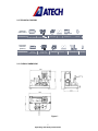
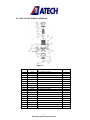
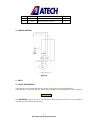
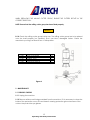
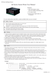
TUCANA-02 P
PORTABLE END MILLING MACHINE
USER’S MANUAL
1
Operating and Safety Instructions
CONTENTS
Page
1. General Information
3
1.1. Introduction
3
1.2. Manufacturer
3
2. Machine’s Description and Purpose of Use
3
2.1. Machine’s description
3
2.2. Technical features
5
2.3. Overall dimensions
5
2.4. Part lists and technical drawings
6
2.5. Wiring diagram
8
3. Safety
8
3.1. Safety information
8
3.2. Accident prevention
9
3.3. General safety information
10
4. Transport of the Machine
11
5. Installation of the Machine
12
5.1. Preparation
12
5.2. Electric connection
12
6. Machine Safety Information
12
7. Operation
13
7.1. Starting to Work
13
8. Installation of the Milling Cutters
14
9. Maintenance
15
9.1. Periodic Checks
15
10. Information About Faulty Use
16
11. Electric Components
16
2
Operating and Safety Instructions
1. GENERAL INFORMATION
1.1 INTRODUCTION
The user’s manual given by the manufacturer contains necessary information about the
machine parts. Each machine operator should read these instructions carefully, and the
machine should be operated after fully understanding them.
Safe and efficient use of the machine for long term depends on understanding and
following the instructions contained in this manual. The technical drawings and details
contained in this manual constitute a guide for the operator.
1.2 DISTRIBUTOR
ATech Machine, Inc.
10752-A Tucker Street – Beltsville, MD 20705 USA
Phone: +1-301-595-1816 Fax: +1-301-560-6627
Website: www.ATechMachinery.com
E-mail: [email protected]
In case of any technical problem please contact your nearest ATECH dealer, or
ATECH head office through the above mentioned phone, fax or e-mail address.
Technical labels with the model description of the machine are fixed onto the front
side of each machine.
The machine’s serial number and manufacturing year are stipulated on the technical
label.
2. MACHINE’S DESCRIPTION and PURPOSE OF USE
2.1. MACHINE’S DESCRIPTION
Portable end milling machine designed for precise end milling operations on PVC and
Aluminum mullion profiles.
The machine has been designed in accordance with the CE Directives.
Clamping and milling operation is manual.
3
Operating and Safety Instructions
Please mention the below mentioned data in all your correspondence regarding the
machine with the manufacturer and/or your ATECH dealer.
*Machine model
*Machine’s serial number
*Voltage and frequency
*Name of dealer where machine was purchased
*Date of purchase
*Description of the machine fault
*Average daily operation period
4
Operating and Safety Instructions
2.2. TECHNICAL FEATURES
Technical
Features
(American)
TUCANA-02 P
800W
120V 60Hz
d=1
"
D=Max 4
3000 rpm
"
--
14x20x17"
66 lbs
Technical
Features
(Metric)
TUCANA-02 P
800W
230V 50Hz
d=30 mm
D=Max.120
3000 rpm
2.3. OVERALL DIMENSIONS
Figure-1
5
Operating and Safety Instructions
--
--
35x51x42 cm
30 kg
2.4. PARTS LIST AND TECHNICAL DRAWINGS
Figure-2
NO.
ORDER NO.
4
5
14
15
17
18
19
20
21
22
25
26
30
31
32
33
35
36
59
111-118
111-119
111-114
223-004
111-116
141-141
142-030
202-001
141-093
141-094
191-004
191-009
113-005
222-006
222-005
163-009
113-004
172-017
192-008
PART NAME
MOVEMENT HOUSING
PROFILE SUPPORT
CAPACITOR HOUSING
BUTTON SWITCH HANDLE A5-12
CUTTER GUARD
SUPPORT END
ROTOR SHAFT
CUTTER GROUP
WASHER 30x8x7
OUTER NUT WASHER
6203 BEARING 17x40x12
6206 BEARING 30x62x16
MOTOR BODY
FAN COVER
FAN
ROTOR
MOTOR BCK COVER
M6x30 HEXAGONAL SCREW
25x35x40 RING
6
Operating and Safety Instructions
QUANTITY
1
1
1
1
1
1
1
1
1
1
1
1
1
1
1
1
1
4
3
62
63
172-026
172-024
M8x20 HEXAGONAL SCREW
M8x30 HEXAGONAL SCREW
1
13
Figure-3
NO.
1
ORDER NO.
111-117
PART NAME
TABLE
2
111-115
SHAFT CONNECTION COLUMN
2
3
144-009
MOVEMENT HOUSING SHAFT
2
4
111-118
MOVEMENT HOUSING
1
6
550-027
MECHANIC CLAMP
2
7
111-099
LOWER CLAMP HOUSING
1
8
111-103
CLAMP SHOE
1
9
111-101
SET SQUARE FENCE
1
10
111-106
UPPER CLAMP HOUSING
1
11
141-142
CLAMP COLUMN SHAFT BOLT
1
12
141-144
CLAMP COLUMN SHAFT
1
13
222-003
CLAMP PLASTIC END
1
16
224-002
FOOT PLASTIC
4
27
180-001
M6x10 SCREW
4
28
177-023
FORK 6 mm WASHER
5
29
172-014
M6x16 HEXAGONAL SCREW
4
7
Operating and Safety Instructions
QTY
1
60
271-008
MOVEMENT SPRING
1
63
172-024
M8x30 HEXAGONAL SCREW
13
64
172-027
M8x25 HEXAGONAL SCREW
4
2.6. WIRING DIAGRAM
Figure-4
3. SAFETY
3.1. SAFETY INFORMATION
The symbols shown hereunder are necessary to be read with special attention.
Not reading or observing of them may cause damage to the equipment or personal injury.
IMPORTANT
The IMPORTANT symbol above is one telling to apply special care and to be careful at
carrying out the specified operation
8
Operating and Safety Instructions
CAUTION !
The CAUTION! Symbol above warns you against specific dangers, and requires to read the
text. Not observing may cause damage to the equipment.
DANGER WARNING
The above symbol DANGER WARNING, warns you against specific dangers, and you have
definitely to read them. Negligence may cause damage to the equipment and bodily
injury.
Read the user’s manual carefully before using the machine or carrying out maintenance
works.
3.2. ACCIDENT PREVENTION
3.2.1 Our machines are manufactured in accordance with EN 60204-1 and EN 292-2 CE
safety directives, which cover national and international safety directives.
3.2.2 It is the task of the employer to warn his staff against accident risks, to train them on
prevention of accidents, to provide for necessary safety equipment and devices for the
operator’s safety.
3.2.3 Before starting to work with the machine, the operator should check the features of
the machine, learn all details of the machine's operation.
3.2.4 Machine should be operated only by staff members, who have read and understood
the contents of this manual.
3.2.5 All directives, recommendations and general safety rules contained in this manual
have to be observed fully. The machine cannot be operated in any way for purposes
other than those described herein. Otherwise, the manufacturer shall not be deemed
responsible for any damages or injuries. And such circumstances would lead to the
termination of the warranty.
9
Operating and Safety Instructions
3.3. GENERAL SAFETY INFORMATION
3.3.1. The power cable should be led in such a way that nobody can step on it or
nothing can be placed on it. Special care has to be taken regarding the inlet and
outlet sockets.
3.3.2. If the power cable should be damaged during operation, don't touch and
unplug it. Never use damaged power cables.
3.3.3. Don’t overload machines for drilling and cutting. Your machine will operate
more safely with power supply in accordance with the stipulated values.
3.3.4. Don’t place your hands between parts in motion.
3.3.5. Use protective eye glasses and ear plugs. Don't wear oversize clothes and
jewels. These can be caught by moving parts.
3.3.6. Keep your working place always clean, dry and tidy for accident prevention
and safe operation.
3.3.7. Use correct illumination for the safety of the operator. (ISO 8995-89 The Lighting
of Indoor Work Systems)
3.3.8. Don't leave anything on the machine.
3.3.9. Don’t use any materials other than those recommended by the manufacturer
for cutting operations on the machine.
3.3.10. Ensure that the work piece is clamped appropriately by the machine's clamp
or vice.
10
Operating and Safety Instructions
3.3.11. Ensure safe working position, always keep your balance.
3.3.12. Keep your machine always clean for safe operation. Follow the instructions at
maintenance and replacement of accessories. Check the plug and cable regularly.
If damaged, let it replace by a qualified electrician. Keep handles and grips free of
any oil and grease.
3.3.13. Unplug first, before conducting and maintenance works.
3.3.14. Ensure that any keys or adjustment tools have been removed before
operating the machine.
3.3.15. If you are required to operate the machine outside, use only appropriate
extension cables.
3.3.16. Repairs should be carried out by qualified technicians only. Otherwise,
accidents may occur.
3.3.17. Before starting a new operation, check the appropriate function of
protective devices and tools, ensure that they work properly. All conditions have to
be fulfilled in order to ensure proper operation of your machine. Damaged
protective parts and equipment have to be replaced or repaired properly (by the
manufacturer or dealer).
3.3.18. Don’t use machines with improper functioning buttons and switches.
3.3.19. Don’t keep flammable, combustive liquids and materials next to the machine and
electric connections.
4. TRANSPORT OF THE MACHINE
IMPORTANT
4.1.1 The transport should be done by qualified personnel only.
4.1.2 The machine should be transported by lifting with proper equipment (not touching
the ground during the transport).
4.1.3 Keep the carton box packing of the machine for future use.
11
Operating and Safety Instructions
5. INSTALLATION OF THE MACHINE
5.1 PREPARATION
5.1.1 The machine's dimension are shown in the Technical Features page (Page 5). Place
the machine onto an even ground, or on the double tray tool cabinet, which is delivered
as option.
5.1.2 The machine should be located approx. 20 cm away from the back wall. The power
connection plug is located on the rear side of the machine.
5.1.3 The machine should be located on an even and solid ground.
5.1.4 At the portable end milling machine TUCANA-02 P all parts are delivered ready for
use.
5.2 ELECTRIC CONNECTION
5.2.1 The phase electric cable socket has to be in accordance with the machine's plug.
5.2.2 Your machine should be operated with 230 V 50 Hz (110V 60Hz).
5.2.3 Plug the machine into a grounded socket.
CAUTION !
5.2.4 Check the power source voltage. It has to be in accordance with the values
stipulated on the machine’s type label.
6. MACHINE SAFETY INFORMATION
6.1.1 It is not allowed to operate the machine with the protective cover and other
protective equipment removed.
6.1.2 Lifting, installation, electric, pneumatic maintenance of the machine should be
carried out by qualified personnel only.
6.1.3 Routine maintenance and scheduled maintenance should be carried out by
qualified personnel after unplugging the machine and disconnecting the air supply first.
6.1.4 Ensure that the machine has been cleaned, tested and maintain before starting to
operate.
12
Operating and Safety Instructions
6.1.5 Check the safety devices, power cable and moving parts regularly. Don’t operate
the machine before having replaced defective safety devices or faulty parts.
6.1.6 Never replace the milling cutters before unplugging first.
6.1.7 Keep foreign materials away from the working area of the machine, keep away from
the machine’s moving parts.
IMPORTANT
The safety data have been defined above. In order to prevent physical damage or
damage to the equipment, please read the safety information carefully and keep the
manual always in an easy accessible place.
7. OPERATION
7.1. STARTING TO WORK
7.1.1 Ensure that the machine table and all kind of parts are clean and dry. Degrease and
dry the machine table. Especially ensure that the holding grips and handles are clean
and dry.
7.1.2 Clean all surfaces of the machine from chip and foreign particles. Use eye glasses for
protection.
7.1.3 Check with the appropriate keys that the milling cutters are tightened well.
7.1.4 Check the milling cutters for wear, bending and breaking. Replace them if
damaged.
7.1.5 Our portable end milling machine TUCANA-02 P is used for working of non-ferrous
materials, aluminum and PVC mullion profiles to make <T > connections.
7.1.6 Place the mullion profile on the machine table and push it forward until it contacts
the stopper (Figure 5, No. 29).
NOTE: The milling length of the mullion profile can be adjusted precisely by loosening the
stopper on the machine (Figure 5, No. 29), and fixing it at the desired length.
7.1.7 Manually clamp the work piece, which you have placed onto the machine table
and pushed forward until touching the stopper, using the two clamps on the machine
(Figure 5, No. 13).
CAUTION !
13
Operating and Safety Instructions
Don’t start to process the work piece before ensuring that it is clamped properly.
7.1.8 Press the Start button (Figure 5, No. 1) to rotate the milling cutter group. While
keeping the Start button pressed, push the cutter group with the handle alongside the
clamped mullion profile, and move it back to its original position after the milling operation
is finished, Release the Start button.
7.1.9 Release the clamps and take out the end milled profile.
INPORTANT
The milling operation has always to be started from the starting position of the machine.
Never start this operation from the opposite side.
NOTE: The milling cutters have to be started freely, without touching the profile. They have
to start to rotate first before making the milling operation.
7.1.10 Release the Start button after the milling operation is finished. The milling cutters will
come to a full stop within approx. 10 sec. after releasing the Stop button.
Figure-5
8. INSTALLATION OF THE MILLING CUTTER CUTTERS
8.1.1 If it becomes necessary to replace the milling cutters for any reason, follow the
following order for replacement:
8.1.2 Unplug the machine.
8.1.3 Remove the milling cutter group after removing the M8x20 hexagonal bolt with the 6
mm hexagonal key shown in Figure-6 No. 33. After replacing the cutter group, tighten
again the hexagonal bolt.
14
Operating and Safety Instructions
WHEN REPLACING THE MILLING CUTTER GROUP, ENSURE THE CUTTERS ROTATE IN THE
CORRECT DIRECTION.
NOTE: Ensure that the milling cutter group has been fixed properly.
CAUTION !
8.1.4 Check the milling cutter group before use. The milling cutter group has to be placed
onto the shaft properly (no vibration). Don’t use blunt, damaged cutters. Check the
machine by running it at least 20 sec. in idle position.
STOCK NO
172-024
202-001
141-093
141-094
179-005
PART NAME
M8x30 ALLEN SCREW
SAW GROUP
WASHER 30x8x7
SAW BLADE SHAFT PULLEY
6 MM ALLEN WRENCH
QTY
14
1
1
1
1
Figure-6
9. MAINTENANCE
9.1. PERIODIC CHECKS
9.1.1 Unplug the machine.
9.1.2 Remove all burr and foreign materials from the machine. If it is necessary to clean the
inside of the protection cover, lift and clean it wearing protective gloves because of the
cutters. Use protective eye glasses.
15
Operating and Safety Instructions
9.1.3 Clean and dry the machine table.
9.1.4 Apply a protective oil film onto the milling cutters and the unpainted parts of the
machine to provide protection against corrosion.
.
10. INFORMATION ABOUT FAULTY USE
10.1.1 Check the plug for power supply.
10.1.2 Keep the Start button pressed until the end milling operation is completed.
10.1.3 This machine is used for end milling operations on PVC and aluminum mullion
profiles in order to achieve <T> connection of profiles.
11. ELECTRIC COMPONENTS
ORDER NO.
PART NAME
QUANTITY
550-028
1.1 kW 230V ELECTRIC MOTOR
1
162-003
CAPACITOR 25 MF 250V
1
164-015
3x1 PRINTED PLUG
1
165-009
PUSH BUTTON
1
16
Operating and Safety Instructions