1
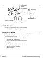
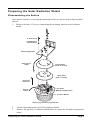
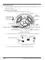
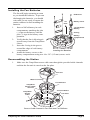
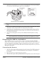
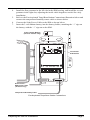
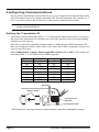
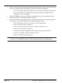
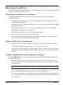
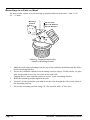
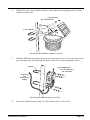
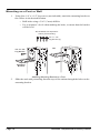
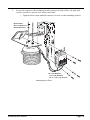
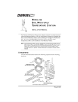
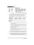
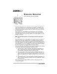
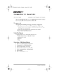
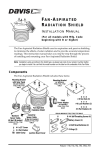
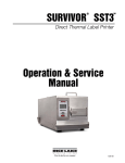
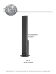
FAN-ASPIRATED
WIRELESS
TE M P E R A T U R E /H U M I D I T Y
S TA T I O N
INSTALLATION MANUAL, REV C
The Fan-Aspirated Wireless Temperature/Humidity Station, referred to in this manual as
the Fan-Aspirated Temp/Hum Station, combines fan aspiration and passive shielding to
minimize the effects of solar radiation on temperature measurement. This manual provides step-by-step instructions for installing your Fan-Aspirated Temp/Hum Station.
Components
The Fan-Aspirated Temp/Hum Station includes these items shown below and on the
next page:
Junction Board Cover
SIM Housing
Mounting Bracket
Fan-Aspirated Radiation Shield
Components, Part 1
Product # 6385
#4 Self-Threading
Screws (4)
Battery Covers (2)
3 Volt Lithium
Battery
1.2 Volt Nicad
Batteries (2)
O-Rings (2)
#8 Hex Nuts (3)
#8 Lock Washers (3)
1-1/2" U-Bolts (2)
#8 Flat Washers (3)
1/4" Flat Washers (4)
1/4" Hex-Nuts (4)
Components, Part 2
Tools Needed
You may need the following tools to install your station:
•
A medium Phillips-Head screwdriver.
•
A small wrench or 3/8” (9 mm) nutdriver.
Installation Steps
The Fan-Aspirated Temp/Hum Station comes pre-assembled. You will, however, need to
partially disassemble your station to prepare it for operation.
Here are the installation steps:
1.
2.
3.
4.
5.
6.
7.
8.
9.
Page 2
Prepare the solar radiation shield for installation.
Prepare the SIM for installation.
Install the Sensor Interface Module (SIM) batteries.
Apply power to the fan.
Reassemble the station.
Configure the DavisTalk™ transmitter ID code.
Test signal reception at the console.
Choose a location for the station.
Mount the station.
Wireless Temperature/Humidity Station
Preparing the Solar Radiation Shield
Disassembling the Station
Open up the station by removing the mounting bracket as shown in the following illustration.
1.
Remove the three (3) screws connecting the mounting bracket to the radiation
shield.
2" Screws (3)
Lock Washers
Flat Washers
Mounting Bracket
Solar Power
Cable
Closed Plate
(no hole in center)
Open Plate
(hole in center)
Direction
of air flow
Fan Plate
Sensor
Cable
Battery Compartment
Junction Board
Removing the Mounting Bracket
2.
3.
Lift the mounting bracket off of the radiation shield.
Remove the top two (2) radiation shield plates to expose the fan plate and junction
board.
Preparing the Solar Radiation Shield
Page 3
Powering the Fan
The Fan-Aspirated Temp/Hum Station fan is solar-powered and uses batteries for overnight power storage.
Connecting Solar Power
1.
Locate the Junction Board on the fan plate (See below).
Fan Plate
Battery
Compartments
#4 x 1/2" Screw
#4 Flat Washer
Cable Clamp
Fan Motor
Sensor Cable
Battery
Wires
Junction Board
SIM Power Cable
Solar Panel Cable
Solar Panel Connector
Solar Power Cable Routing
2.
Connect the solar power cable to the VSOL connector on the Junction Board.
SIM Power Cable
Solar Power Connector
Fan Connector
MOTOR
+VSOL
Junction Board Connections
3.
Page 4
Secure the cables to the fan plate with the supplied cable clamp.
Wireless Temperature/Humidity Station
Installing the Fan Batteries
The fan will begin operating as soon
as you install the batteries. To prevent
discharging the batteries, you should
wait until you are ready to mount the
station outdoors before installing the
batteries.
1.
2.
3.
4.
#4 Screws
Air
Flow
Insert a NiCad battery in each
compartment, matching the plus
(+) sign on the battery with the
plus (+) sign in the battery compartment.
Verify that the fan is blowing air
up and away from the Temp/Hum
sensor.
Insert the O-ring in the groove
around the edge of each battery
compartment.
Installing the Batteries
Attach the battery covers to the
battery compartments using two #4 x 3/8” (9.5 mm) screws each.
Battery Cover
1.2 Volt Nicad
Battery
O-Ring
Battery
Compartment
Reassembling the Station
1.
Make sure the Temp/Hum sensor cable runs through the provided cable channels
and that the fan unit is seated on the fan plate.
Fan Unit
Motor Connector
Fan Deflector
Temp/Hum
Sensor Cable
Channel
Temp/Hum
Sensor
Cable
Junction Board
Fan Plate
Sensor Cable Channel in Fan Plate and Fan Deflector
Preparing the Solar Radiation Shield
Page 5
2.
Install the Junction Board Cover as shown in the illustration. The Junction Board
Cover presses easily into place when you are installing it.
Junction Board
Cover
Note:
Press in on Sides
near latches to
install or remove
cover.
Junction
Board
Junction Board Cover Installation
Note: To remove the cover, press gently in on both sides to release the latches holding it in
place.
3.
4.
5.
Place the two radiation shield plates on top of the fan plate, open plate first with the
closed plate on top, being careful to line up the three screw holes.
Gently place the mounting bracket on top of the radiation shield, being careful to
line up the three screw holes and also being very careful not to move the top two
(2) radiation shield plates.
Fasten the mounting plate securely to the radiation shield using three (3) long
screws.
Tip:
Hold the mounting bracket in place with one hand while you start the three (3)
long screws.Be sure to start all three screws before you tighten any of them.
Preparing the SIM for Installation
The Temp/Hum sensors are connected by a cable to the Sensor Interface Module
(SIM), located inside the SIM housing. The SIM contains electronics that measure and
store the temperature and humidity values for transmission to the console via cable or
radio. The SIM housing protects the SIM from the elements and provides easy access to
SIM cable connections.
Connecting the Sensors
1.
2.
3.
Page 6
Take one of the square rubber grommets from the bottom of the SIM housing and
run the cables for the UV and Solar Radiation sensors through it, if included on
your station.
Run the Solar Power cable through the grommet.
Take the other square rubber gromment and run Temp/Hum sensor cable through it.
Wireless Temperature/Humidity Station
4.
5.
6.
7.
Install the first grommet in the left slot in the SIM housing, and install the second
grommet in the right slot, adjusting the inside cable lengths as needed for a tidy
installation.
Refer to the Fan-Aspirated Temp/Hum Station Connections illustration below and
connect the temperature/humidity sensor cable as shown below.
Connect the Solar Power Cable to the SIM as shown below.
Insert the 3-volt lithium battery into the battery holder, matching the “+” sign on
the battery with the “+” sign on on the SIM.
3-Volt Lithium Battery
(wireless models only)
Transmitter
ID Switches
UV
UV
SUN RAIN WIND
TEMP
SUN RAIN WIND HUM
Solar Power /
SIM Power Cable
(wireless only)
Temperature/Humidity Cable
Fan-Aspirated Temp/Hum Station Connections
Preparing the SIM for Installation
Page 7
Configuring Communications
Each wireless transmitting station must be set to one of eight DavisTalk transmitter IDs,
and each station must use a unique transmitter ID. Use the transmitter ID switches #1, 2
and 3 to set the station’s ID. Switch #4 is only used for transmission testing.
Note: The transmitter and receiver communicate with each other only when both are set
to the same DavisTalk ID.
Setting the Transmitter ID
The factory default transmitter ID is “1”. Looking at the table shown below you can see
that means the transmitter ID switches are in the OFF position when each transmitting
station leaves the factory.
Your Fan-Aspirated Temp/Hum Station requires a different DavisTalk transmitter ID
than your Integrated Sensor Suite (ISS) or any other DavisTalk-compatible wireless station you may be using.
Use a ballpoint pen or paper clip to toggle DIP switches #1, 2, and 3. The settings for
transmitter IDs 1 – 8 are shown in the following table:
ID CODE
SWITCH 1
SWITCH 2
SWITCH 3
#1 (default)
#2
#3
#4
#5
#6
#7
#8
off
off
off
off
ON
ON
ON
ON
off
off
ON
ON
off
off
ON
ON
off
ON
off
ON
off
ON
off
ON
.
Antenna
Battery Holder
ON
1234
Transmitter ID
Switches
Test Indicator LED
DIP Switches in Top-right Corner of SIM (Illustration has been enlarged for clarity)
Page 8
Wireless Temperature/Humidity Station
Setting the Console to ID
Note: See the Vantage Pro User’s Manual & Setup Guide: “Setup Mode – Screen 2:
Selecting Transmitters” for more detailed instructions.
1.
2.
3.
4.
5.
Put your console into Setup Mode — press and hold the DONE key and press the
DOWN arrow key.
The console will display Screen 1: Transmitters. You should see the words:
“RECEIVING FROM...” and “STATION NO.” followed by the transmitter IDs that
your console detects. One of these should be the ID number you just set on the station’s transmitter. If you don’t see it, move the console to within 10' of the transmitter and verify that the station’s transmitter ID switches have been set correctly. If
you still don’t see station’s ID, refer to “Troubleshooting Communications” on
page 10.
Press the DONE key to move on to Screen 2: Selecting Transmitters.
Setup Mode – Screen 2 is where you will set the console to recognize the signals
from your Aspirated Temp/Hum Station.
Press the LEFT or RIGHT arrow key, or the STATION key, to scroll through transmitter IDs.
When you see the transmitter ID you chose for your station, use the UP or DOWN
arrow keys to set the reception of that ID code to “ON”.
Press the GRAPH key to change the station assigned to that transmitter ID to
“TEMP HUM”.
To exit Setup Mode, press and hold the DONE key.
Testing Communications
Press the TEMP key until you see an ‘outside’ temperature displayed on the console
screen, with the correct Station No. displayed above or below it. Do the same with the
HUM key. This confirms communication between your transmitting station and the console.
Note: It may take up to one minute for data from your Fan-Aspirated Temp/Hum Station
to appear on the console after you have exited the Setup Mode.
Troubleshooting Communications
1.
2.
3.
4.
Verify that the console is powered and is not in Setup Mode (exit Setup Mode by
pressing DONE key and holding it for a moment).
On the Fan-Aspirated Temp/Hum Station, check that the battery is properly
installed.
Walk around the room with the console, standing for a few moments in various
locations to see if you are picking up signals.
If you don’t see readings no matter where you stand with the console, use the station’s TEST mode to perform additional troubleshooting procedures.
Switch #4 on the SIM (see illustration on page 8) controls the station’s test mode.
Configuring Communications
Page 9
5.
Set the switch to the ON position using a ball-point pen or paper clip. When in test
mode, an LED indicator light flashes each time the station transmits:
• The LED will immediately flash once to show that the light itself functions.
6.
7.
• Then it will flash each time the transmitter broadcasts a signal, which
should be every 10 seconds.
If the LED flashes only once and then remains dark, there is a problem with the
transmitter. Refer to Troubleshooting on page 17.
If the LED flashes repeatedly but your console isn’t picking up a signal anywhere
in the room, it could be related to one of the following causes:
• The ID switches were not correctly set on the transmitter.
• Review the procedure on page 8.
• The station ID was not correctly set on the console/receiver.
• Review the procedure on page 9.
• Reception is being disrupted by RF (radio frequency) interference.
• There is a problem with the console/receiver.
• Refer to Troubleshooting, page 17.
Note: Remember to set the Test switch OFF when you’re finished testing wireless transmission. If it is left ON, the blinking LED will significantly reduce battery life.
Page 10
Wireless Temperature/Humidity Station
Mounting the Station
The Fan-Aspirated Temp/Hum Station can be mounted on a pole or on a vertical surface
such as a wooden post, wall or fence.
Choosing a Location for the Station
Consider the following factors as you choose a location for your Fan-Aspirated
Temp/Hum Station:
•
Mount the station facing South in the Northern Hemisphere and Facing North in
the Southern Hemisphere.
•
Mount the station so that the solar panel receives the most available direct sunlight
throughout the day.
•
Mount the station at least 5’ (1.5m) away from any source of cold or heat that
might distort temperature measurements.
•
Mount the station at least 5’ (1.5m) above the ground.
•
Mount the station over plants or soil if possible.
•
Do not install over or near sprinklers. The radiation shield is not designed to protect sensors from water that is sprayed upwards.
Range of Wireless Transmission
•
The range of wireless transmission is up to 400’ (125 m) outdoors, line of sight.
•
Typical range under most conditions is 75’ to 150’ (23 to 46 m).
•
Your range may be reduced by walls, ceilings, foliage, metal structures, and radio
interferance. Cordless phones and ham radios are common sources of radio interferance.
Testing Transmission from Proposed Location
It is very important to test reception from the proposed location before permanently
mounting the station.
•
Place the station at the intended mounting site, or have someone hold it there, so
you can test reception at your Vantage Pro console or other DavisTalk receiver for
a few minutes.
Note:Rotating the Vantage Pro console’s antenna may help to improve reception.
•
Take your time and be sure to test wireless reception anywhere you might want to
use or mount your console or other receiver now or in the future.
•
If you aren’t picking up strong signals where you intend to place your console, better to move the station now than after it has been mounted. Experiment to find the
best reception.
Mounting the Station
Page 11
Mounting on a Pole or Mast
For best results, mount to a pole having an outside diameter between 1" and 1-1/4"
(25 – 31 mm).
Mounting
Bracket
#8 Hex Nuts
#8 Lock Washers
#8 Flat Washers
Attaching Temperature/Humidity
Station to Mounting Bracket
1.
2.
3.
4.
5.
Page 12
Slide the stud ends protruding from the top of the radiation shield through the holes
on the mounting bracket.
Secure the radiaition shield to the mounting bracket using a #8 flat washer, #8 split
lock washer and #8 hex nut one each of the stud ends.
Tighten the hex nuts until the station is secure on the mounting bracket.
Hold the mounting bracket against the pole.
Put two U-bolts around the pole and insert the ends through the holes in the back of
the mounting bracket.
Secure the mounting bracket using 1/4" flat washers and 1/4" hex nuts.
Wireless Temperature/Humidity Station
6.
Tighten four set of the washers and hex nuts until the mounting bracket is firmly
mounted on the pole.
1/4" Hex Nuts
1/4" Flat Washers
1-1/2" U-Bolts
Mounting the Radiation Shield on a Pole
7.
Hold the SIM housing against the pole near the station. Put two U-bolts around the
pole and insert the ends through the holes in the back of the mounting bracket.
U-Bolts
1/4" Flat Washers
1/4" Lock Washers
1/4" Hex Nuts
Temp/Hum
and
Solar Power
Cables
Mounting the SIM Housing on a Pole
8.
Secure the SIM housing using 1/4" flat washers and 1/4" hex nuts.
Mounting the Station
Page 13
Mounting on a Post or Wall
1.
Using four 1/4" x 1-1/2" lag screws (not included), attach the mounting bracket to
the surface in the desired location.
• Drill holes using a 3/16" (5 mm) drill bit.
• Use a carpenter’s level when marking the holes, to ensure that the bracket
will be level.
Not included, but requred for
wall or post mounting:
1/4" x 1-1/2"
Lag Screws (4)
1/4" x 1-1/2"
Lag Screws
OR
Mounting
Bracket
Attaching Mounting Bracket to a Post
2.
Page 14
Slide the stud ends protruding from the top of the station through the holes on the
mounting bracket.
Wireless Temperature/Humidity Station
3.
Secure the station to the mounting bracket using a #8 flat washer, #8 split lock
washer and #8 hex nut on each of the stud ends.
• Tighten the hex nuts until the station is secure on the mounting bracket.
#8 Hex Nuts
#8 Lock Washers
#8 Flat Washers
1/4" Flat Washers
1/4" Lock Washers
1/4" x 1-1/2" Lag Screws
Mounting to a Post
Mounting the Station
Page 15
Installation Options
Batteries
The Fan-Aspirated Temp/Hum Station is solar powered and is supplied with two NiCad
C-cell batteries. At your option you may decide to install either zero, one, or two C-cell
batteries.
•
Install two fan batteries for maximum length of overnight aspiration but with
slightly lower average daytime aspiration.
•
Install only one fan battery for some overnight aspiration but with slightly higher
average daytime aspiration.
•
Install no batteries for maximum daytime aspiration and no nighttime aspiration.
Wireless Repeater
A wireless repeater (#7624 or #7625) can be used to extend the range of wireless transmission between the station and the Vantage Pro console.
Maintenance
•
Keep the surfaces clean, since the Fan-Aspirated Temp/Hum Station is less effective when the surfaces are dirty. Remove dust from the solar panel and the shield
with a damp cloth.
•
Remove any debris obstructing air flow through the radiation shield, e.g., leaves,
twigs, webs, and nests.
•
Avoid spraying insect killer of any kind into the radiation shield as this may damage the sensors and the shield.
•
Once a year: replace the motor (Part # 7758 or #7759), batteries (solar-powered
models only), and remove any debris lodged inside the unit.
Page 16
Wireless Temperature/Humidity Station
Annual Maintenance
We recommend replacing the fan motor and fan batteries once a year.
1.
2.
3.
4.
5.
6.
7.
8.
9.
Retrieve your Fan-Aspirated Temp/Hum Station and place on a stable work surface.
Disassemble the Radiation Shield (See page 3).
Clean any debris lodged inside the unit.
Unplug the old motor and remove from it from the Radiation Shield (See page 5).
Install the new motor/fan assembly (#7758) and plug it into the Junction
Board (See page 5).
Remove the old fan batteries (See page 5).
Install new batteries (two (2) NiCad C-cells).
Assemble the Radiation Shield (See page 5).
Re-mount the Fan-Aspirated Temp/Hum Station in its previous location.
Troubleshooting
If you are experiencing problems with your Fan-Aspirated Temp/Hum Station, first be
sure to check all cable connections. If you are unable to solve the problem, please call
Davis Technical Support. We’ll be glad to help. Most questions can be answered over
the phone. You can also email us for support or visit our website. Sorry, we are unable to
accept collect calls.
•
For communications problems, see “Troubleshooting Communications” on
page 10.
Note: Please do not return items to the factory for repair without prior authorization.
Contacting Davis Instruments
(510) 732-7814 for Technical Support, Monday – Friday, 7:00 a.m. – 5:30 p.m. Pacific
Time.
[email protected] E-mail to Technical Support.
(510) 670-0589 Fax to Customer Service or Tech Support.
www.davisnet.com Copies of User Manuals are available on the “Support” page.
Watch for FAQs and other updates. Subscribe to the e-newsletter.
Troubleshooting
Page 17
Theory of Operation
The diagram below shows how the Fan-Aspirated Temp/Hum Station draws outside air
up through the sensor chamber and between the three walls surrounding the sensor
chamber.
Cross-section of Fan-Aspirated Radiation Shield
Page 18
Wireless Temperature/Humidity Station
Specifications
Temperature and Humidity Station
Temperature range: . . . . . . . . . . . . . . . . . –40 to 140° Fahrenheit (–40 to 60°
Celsius)
Wireless transmission frequency: . . . . . . . 916.5 MHz, (868.35 MHz for overseas
version – Product # includes “XA”)
Transmitter ID codes: . . . . . . . . . . . . . . . 8 user-selectable
License: . . . . . . . . . . . . . . . . . . . . . . . . . . low power (less than 1 mW), no license
required
Primary power input: . . . . . . . . . . . . . . . . CR-123A 3-volt lithium battery
Secondary (backup) power: . . . . . . . . . . . Optional Vantage Pro AC power adapter
Fan-Aspirated Radiation Shield
Aspiration Rate, Full Sun . . . . . . . . . . . . . 190 feet/min (.96 m/s)
Aspiration Rate, Batteries Only . . . . . . . . 80 feet/min (9.4 m/s)
Radiation-Induced Temperature Error . . . . 0.5°F (0.3°C)
[At solar noon, insolation = 1040 W/m2]
(Reference: RM Young model 43408)
Operating Temperature . . . . . . . . . . . . . . –40° to +140° F (–40° to +60° C)
Non-operating Temperature . . . . . . . . . . . –50° to +158° F (–45° to +70° C)
Station Primary Power Input . . . . . . . . . . . CR-123A 3-volt lithium battery
(approximately one year battery life)
Fan Primary Power Input . . . . . . . . . . . . . solar panel
Fan secondary power . . . . . . . . . . . . . . . . 1 or 2 - 1.2 Volt NiCad C-cells
Page 19
FCC Part 15 Class B Registration Warning
This equipment has been tested and found to comply with the limits for a class B digital device, pursuant
to Part 15 of the FCC Rules. These limits are designed to provide reasonable protection against harmful
interference in a residential installation. This equipment generates, uses and can radiate radio frequency
energy and, if not installed and used in accordance with the instructions, may cause harmful interference
to radio communications. However, there is no guarantee that interference will not occur in a particular
installation.
If this equipment does cause harmful interference to radio or television reception, which can be determined by turning the equipment off and on, the user is encouraged to try to correct the interference by one
or more of the following measures:
•
Reorient or relocate the receiving antenna.
•
Increase the separation between the equipment and receiver.
•
Connect the equipment into an outlet on a circuit different from that to which the receiver is
connected.
•
Consult the dealer or an experienced radio/TV technician for help.
Changes or modifications not expressly approved in writing by Davis Instruments may void the user's
authority to operate this equipment.
Product Number: 6385
Davis Instruments Part Number: 7395.153
Fan-Aspirated Wireless Temperature/Humidity Station Installation Manual
Rev.C (June 26, 2003)
© Davis Instruments Corp. 2001-2003. All rights reserved.
This product is protected in the United States by Patent Number 6,247,360.
FCC ID: IR2DWW6326
3465 Diablo Avenue, Hayward, CA 94545-2778 U.S.A.
510-732-9229 • Fax: 510-732-9188
E-mail: [email protected] • www.davisnet.com