1
BX-PIB0x
3rd Generation Intel® Core™ i7/i5/i3 Embedded Box System
User’s Manual
Version 100
October 3, 2014
C&T Solution Inc.
17F-2, No. 700, Zhongzheng Rd., Zhonghe Dist., New Taipei City 235, Taiwan
Tel: 886-2-7731-7888
http://www.candtsolution.com
BX-PIB0x Embedded Box System
Preface
Revision History
Rev.
Date
Description
100
03/10/2014
Initial release
Disclaimer
All specifications and information in this User’s Manual are believed to be
accurate and up to date. C&T Solution Inc. does not guarantee that the
contents herein are complete, true, accurate or non-misleading. The
information in this document is subject to change without notice and does not
represent a commitment on the part of C&T Solution Inc.
C&T Solution Inc. disclaims all warranties, express or implied, including,
without limitation, those of merchantability, fitness for a particular purpose with
respect to contents of this User’s Manual. Users must take full responsibility for
the application of the product.
Copyright Notice
All rights reserved. No part of this manual may be reproduced or transmitted in
any form or by any means, electronic or mechanical, including photocopying,
recording, or information storage and retrieval systems, without the prior
written permission of C&T Solutions Inc.
Copyright © 2014 C&T Solutions Inc.
2
BX-PIB0x Embedded Box System
Trademarks Acknowledgment
Intel®, Celeron® and Pentium® are trademarks of Intel Corporation.
Windows® is registered trademark of Microsoft Corporation.
AMI is trademark of American Megatrend Inc.
IBM, XT, AT, PS/2 and Personal System/2 are trademarks of International
Business Machines Corporation
All other products and trademarks mentioned in this manual are trademarks of
their respective owners.
Environmental Protection Announcement
Do not dispose this electronic device into the trash while discarding. Please
recycle to minimize pollution and ensure environment protection.
3
BX-PIB0x Embedded Box System
Safety Precautions
Before installing and using the equipment, please read the following
precautions:
z Put this equipment on a reliable surface during installation. Dropping it or
letting it fall could cause damage.
z The power outlet shall be installed near the equipment and shall be easily
accessible.
z Turn off the system power and disconnect the power cord from its source
before making any installation. Be sure both the system and the external
devices are turned OFF. Sudden surge of power could ruin sensitive
components. Make sure the equipment is properly grounded.
z When the power is connected, never open the equipment. The equipment
should be opened only by qualified service personnel.
z Make sure the voltage of the power source is correct before connecting the
equipment to the power outlet.
z Disconnect this equipment from the power before cleaning. Use a damp
cloth. Do not use liquid or spray detergents for cleaning.
z Avoid the dusty, humidity and temperature extremes.
z Do not place heavy objects on the equipment.
z If the equipment is not used for long time, disconnect it from the power to
avoid being damaged by transient over-voltage.
z
z
z
The storage temperature shall be above -20°C and below 80°C.
The computer is provided with a battery-powered real-time clock circuit.
There is a danger of explosion if incorrectly replaced. Replace only with the
same or equivalent type recommended by the manufacturer.
If one of the following situation arises, get the equipment checked be
service personnel:
The power cord or plug is damaged.
Liquid has penetrated into the equipment.
The equipment has been exposed to moisture.
The equipment does not work well or it cannot work according the
user’s manual.
The equipment has been dropped and damaged.
The equipment has obvious signs of breakage.
4
BX-PIB0x Embedded Box System
Table of Contents
Preface............................................................................................................2
Revision History ...................................................................................................2
Disclaimer.............................................................................................................2
Copyright Notice...................................................................................................2
Trademarks Acknowledgment..............................................................................3
Environmental Protection Announcement ............................................................3
Safety Precautions ...............................................................................................4
1.
2.
Introduction.............................................................................................8
1.1
Product Description ..............................................................................8
1.2
Specifications .......................................................................................9
1.3
Available Models ................................................................................11
1.4
Mechanical Drawing ...........................................................................12
1.4.1
BX-PIB01 Dimensions .......................................................................... 12
1.4.2
BX-PIB02/03 Dimensions ..................................................................... 13
1.4.3
BX-PIB0x Wall Mount Dimensions ....................................................... 14
Getting Started......................................................................................15
2.1
Preparation .........................................................................................15
2.2
Chassis Layout ...................................................................................16
2.2.1
Front View............................................................................................. 16
2.2.2
Rear View ............................................................................................. 16
2.2.3
PCI/PCIe Expansion Slots .................................................................... 17
2.3
3.
Installing Internal Components ...........................................................18
2.3.1
Removing the Top Cover...................................................................... 18
2.3.2
Installing a CPU .................................................................................... 19
2.3.3
Installing Memory Modules ................................................................... 20
2.3.4
Installing Mini-PCIe Cards .................................................................... 21
2.4
Installing a 2.5” SATA Drive ...............................................................22
2.5
Installing a PCI/PCIe Expansion Card ................................................24
2.6
Installing the Wall Mount Brackets .....................................................26
2.7
Driver Installation................................................................................28
Connectors & Jumpers ........................................................................29
3.1
Power Connector................................................................................29
3.2
External Reset Connector ..................................................................29
3.3
External Power Switch Connector ......................................................29
5
BX-PIB0x Embedded Box System
3.4
Keyboard & Mouse Connectors..........................................................29
3.5
COM1-4 (RS-232/422/485, BIOS Selectable) ....................................30
3.5.1
COM1-4 in RS-232 Mode ..................................................................... 30
3.5.2
COM1-4 in RS-422 Mode ..................................................................... 30
3.5.3
COM1-4 in RS-485 Mode ..................................................................... 30
3.5.4
COM1-4 RS-232/422/485 Mode Selection ........................................... 30
3.6
VGA Connector ..................................................................................32
3.7
GPIO Connector .................................................................................32
3.8
DisplayPort Connector........................................................................32
3.9
HDMI Connector.................................................................................33
3.10
USB 3.0 Connectors...........................................................................33
3.11
USB 2.0 Connectors...........................................................................33
3.12
Front Audio Jacks...............................................................................34
3.13
LAN Connectors .................................................................................34
3.14
Mini-PCIe Connectors ........................................................................34
3.14.1
Mini-PCIe (CN22).................................................................................. 35
3.14.2
Mini-PCIe (CN23).................................................................................. 35
3.15
4.
Jumpers..............................................................................................36
3.15.1
Jumper Locations.................................................................................. 36
3.15.2
Clear CMOS (JP3) ................................................................................ 36
3.15.3
GPIO Output (JP6)................................................................................ 36
3.15.4
BIOS Module Selection (JP7, JP8)....................................................... 37
System BIOS .........................................................................................38
4.1
Main....................................................................................................38
4.2
Advanced............................................................................................39
4.2.1
ACPI Settings........................................................................................ 40
4.2.2
CPU Configuration ................................................................................ 41
4.2.3
SATA Configuration .............................................................................. 42
4.2.4
Intel Rapid Start Technology ................................................................ 43
4.2.5
PCH-FW Configuration ......................................................................... 44
4.2.6
AMT Configuration ................................................................................ 45
4.2.7
USB Configuration ................................................................................ 46
4.2.8
Hardware Monitor ................................................................................. 47
4.2.9
F81801 H/W Monitor............................................................................. 48
4.2.10
F81866 Super IO Configuration............................................................ 49
4.2.11
F81866 H/W Monitor............................................................................. 51
4.2.12
Serial Port Console Redirection............................................................ 52
4.2.13
CPU PPM Configuration ....................................................................... 53
6
BX-PIB0x Embedded Box System
4.2.14
4.3
5.
Intel I210 Gigabit Network Connection ................................................. 54
Chipset ...............................................................................................55
4.3.1
PCH-IO Configuration ........................................................................... 56
4.3.2
System Agent Configuration ................................................................. 60
4.4
Boot ....................................................................................................65
4.5
Security...............................................................................................68
4.6
Save and Exit .....................................................................................69
Address Map .........................................................................................70
5.1
I/O Port Address Map .........................................................................70
5.2
Interrupt Controller (IRQ) Map ............................................................72
5.3
Memory Map.......................................................................................75
7
BX-PIB0x Embedded Box System
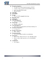
1. Introduction
1.1
Product Description
The BX-PIB0x is a compact embedded system that is ideal for limited space.
Its fanless design with solid sealed aluminum enclosure provides the ideal
solution for high-vibration and dusty environments.
The BX-PIB0x is an embedded system that supports 3rd Generation Intel®
Core™ i7/i5/i3 and Celeron processors (Socket G2) with Intel® QM77 Express
chipset. It has two 204-pin DDR3/DDR3L SODIMM sockets for memory
maximum up to 32GB. Featured are a full range of I/O, including two Gigabit
Ethernet ports, four USB 3.0 ports, two USB 2.0 ports, one 8-bit GPIO port,
VGA/HDMI/DisplayPort graphics outputs, and four RS-232/RS-422/RS-485
serial ports. Two external 2.5” SATA drive bays provide swappable storage,
while two Mini-PCle slots for 3G/Wi-FI and optional 2x PCI/PCIe slots are
available for expansion.
The BX-PIB0x is based on the CT-CIB61 COM Express Type 6 Module. For
more detailed information (including watchdog timer configuration), please
refer to the CT-CIB61 User’s Manual:
http://www.candtsolution.com/product_detail/63.
8
BX-PIB0x Embedded Box System
1.2
Specifications
CPU
¾ 3rd Generation Mobile Intel® Core™ i7/i5/i3 or Celeron
Processor (Socket G2 - FCPGA988)
à Intel® Core™ i7-3610QE Processor
à Intel® Core™ i5-3610ME Processor
à Intel® Core™ i3-3120ME Processor
à Intel® Celeron® Processor 1020E
Chipset
¾ Intel® QM77 Express Chipset
System Memory
¾ Two 204-pin DDR3 /DDR3L SODIMM sockets
¾ Up to 1600MHz
¾ Up to 32GB
BIOS
¾ AMI uEFI BIOS
¾ 8MB SPI Flash ROM
iAMT
¾ iAMT8.0
Graphics
¾ Intel® HD Graphics 4000 integrated on processor
¾ Supports up to three displays
¾ Resolution up to 2560x1600
¾ VGA interface supports up to WQXGA 2560x1600
¾ DisplayPort up to 1920x1200
¾ HDMI up to 2560x1600
Ethernet
¾ Intel® 82579LM GbE PHY
¾ Intel® 1210AT GbE Controller
¾ Two 10/100/1000BASE-T
Audio
¾ Realtek ALC886 HD audio codec
USB Interfaces
¾ Two USB 2.0 ports
¾ Four USB 3.0 ports
Serial Ports
¾ Four RS-232/422/485
9
BX-PIB0x Embedded Box System
Expansion Interfaces
¾ Two Mini-PCIe slots (full and half size) for 3G/Wi-FI
¾ 1x PClex 16 slot, 1x PCle x4 slot (BX-PIB02 model)
¾ 2x PCI slots (BX-PIB03 model)
¾ SlM card socket
8-bit GPIO
PS/2 KB/MS
Storage
¾ Two 2.5” SATA swappable drive bays
Watchdog Timer
H/W Monitor
Power Management
¾ ACPI 3.0 compliant
Power Input
¾ DC +9V ~ +36V input
Power Management
¾ ACPI (Advanced Configuration and Power Interface) 3.0
Operating Temperature
¾ 0°C to 60°C
Storage Temperature
¾ -20°C - +80°C
Operating Humidity
¾ 10% to 90% relative humidity, non-condensing
Dimensions
¾ 266.0 x 98.4 x 228.5 mm (W x H x D) - BX-PIB01 model
¾ 266.0 x 148.6 x 228.5 mm (W x H x D) - BX-PIB02/03
models
Certifications
¾ FCC Class A
10
BX-PIB0x Embedded Box System
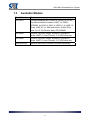
1.3
Available Models
Model Number
Features
BX-PIB01
Fanless Barebone Box System w/ Socket G2 for 3rd
Gen Mobile lntel® Processor, QM77, 2x DDR3
SODIMM, 4x COM, 2x GbE, 4x USB 3.0, 2x USB 2.0,
Audio, iAMT 8.0, 1x SlM card socket, 2x Mini-PCle
slots, 2x 2.5” SATA drive bays, PS/2 KB/MS
BX-PIB02
1xDDR3, 6xCOM, 2xGbE, 4xUSB3.0, 2xUSB2.0,
Audio, iAMT7.0, mini-PCIe slot, 2.5” HDD drive bay
BX-PIB03
1xDDR3, 6xCOM, 2xGbE, 4xUSB3.0, 2xUSB2.0,
Audio, iAMT7.0, mini-PCIe slot, 2.5” HDD drive bay
Wall Mount Kit
Optional wall mount brackets (ordered separately)
11
BX-PIB0x Embedded Box System
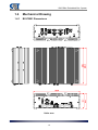
1.4
Mechanical Drawing
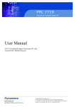
1.4.1
BX-PIB01 Dimensions
Units: mm
12
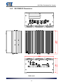
BX-PIB0x Embedded Box System
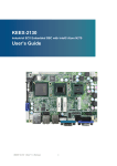
1.4.2
BX-PIB02/03 Dimensions
Units: mm
13
BX-PIB0x Embedded Box System
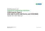
1.4.3
BX-PIB0x Wall Mount Dimensions
Units: mm
14
BX-PIB0x Embedded Box System
2. Getting Started
The following chapter describes how to set up and operate the BX-PIB0x.
2.1
Preparation
Unpack the contents of the shipping carton. Please check that your package
contains the items below. If you discover damaged or missing items, please
contact your vendor.
BX-PIB0x Embedded Box System
AC-to-DC Adapter (90W, 100-240V 2.5A 50~60Hz in,
19VDC 4.73A out)
Driver DVD
Accessory pack
WARNING:
Do NOT install or apply power to equipment that is damaged or
if there is missing/incomplete equipment. Retain the shipping
carton and packing materials for inspection. Please contact
your dealer/vendor immediately for assistance. Obtain
authorization from your dealer before returning any product.
Place the system on a flat work surface. Ensure there is sufficient airflow
clearance around the chassis.
CAUTION:
To prevent damage to the system, ensure there is sufficient
clearance around the air vents for unrestricted airflow. The air
temperature inside the enclosure could rise above the specified
operating temperature limits if the airflow through the vents is
restricted.
15
BX-PIB0x Embedded Box System
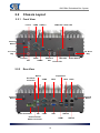
2.2
Chassis Layout
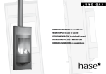
2.2.1
Front View
Line-In
COM4 USB 3.0
LAN2 LED LAN1 LED
Antenna
Mount
2.5” Drive
Bay
2.5” Drive
Bay
Line-Out
Mic
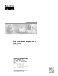
2.2.2
COM3
HDMI2
SIM Card
Slot
HDD LED
Power Switch
Power LED
Rear View
DisplayPort
Mouse
Ext. Reset
Connector
COM2
LAN1 LAN2
GPIO
Antenna
Mount
Antenna
Mount
Power Connector
KB
COM1
VGA
External Power
Switch Connector
USB 3.0
HDMI
16
USB 2.0
BX-PIB0x Embedded Box System
2.2.3
PCI/PCIe Expansion Slots
BX-PIB02/03 models only
PCI/PCIe Slot
PCI/PCIe Slot
17
BX-PIB0x Embedded Box System
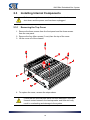
2.3
Installing Internal Components
Before removing the cover, make sure the system has been
shut down and the power cord has been unplugged.
CAUTION:
2.3.1
Removing the Top Cover
1. Remove the three screws from the front panel and the three screws
from the rear panel.
2. Remove the four Allen screws (3 mm) from the top of the cover.
3. Lift the cover off of the chassis.
4. To replace the cover, reverse the steps above.
CAUTION:
Check that the thermal pads have not been damaged. Improper
thermal contact between the heat spreader and heat sink may
result in overheating and damage to the system.
18
BX-PIB0x Embedded Box System
2.3.2
Installing a CPU
1. Remove the four screws securing the heat pipe assembly to each side
of the chassis.
2. Remove the five screws securing the main heat spreader to the COM
Express module.
3. Carefully lift the thermal module assembly out of the chassis, being
careful not to bend the heat pipes.
4. Remove any protective films from the heat spreader as required.
5. Install the CPU.
5. Replace the thermal module assembly into the chassis and reverse the
steps above to secure it.
CAUTION:
Check that the thermal pads have not been damaged. Improper
thermal contact between the heat spreader and heat sink may
result in overheating and damage to the system.
19
BX-PIB0x Embedded Box System
2.3.3
Installing Memory Modules
1. Remove the cover from the chassis as described above.
2. Locate the memory socket at the left hand side when facing the front
panel.
3. Insert the memory module into the socket.
4. Push down firmly on the module until it is locked by two latches
5. Replace the cover as described above.
20
BX-PIB0x Embedded Box System
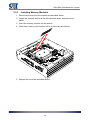
2.3.4
Installing Mini-PCIe Cards
1. Remove the cover from the chassis as described above.
2. Insert the Mini-PCIe card(s) into the slots as shown.
CN23
CN22
3. Secure with screws and attach antennas as required.
4. Replace the cover as described above.
21
BX-PIB0x Embedded Box System
2.4
Installing a 2.5” SATA Drive
CAUTION:
Before installing or removing a SATA drive, make sure the
system has been shut down and the power cord has been
unplugged.
1. Loosen the two large knurled screws securing the drive tray to the front
panel of the system and pull the tray out of the chassis.
2. Slide the 2.5” SATA drive into the drive tray with the bottom side facing
upwards as shown by arrow “1”. Secure the drive to the tray by securing
four screws (included in the accessory pack) as indicated by “2”.
22
BX-PIB0x Embedded Box System
3. Insert the drive assembly into the chassis and secure it by tightening the
two large knurled screws.
23
BX-PIB0x Embedded Box System
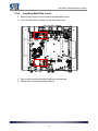
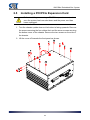
2.5
Installing a PCI/PCIe Expansion Card
CAUTION:
Before installing or removing a PCI/PCIe expansion card, make
sure the system has been shut down and the power cord has
been unplugged.
1. Turn the chassis upside down so the bottom is facing upwards. Remove
the screws securing the four rubber feet and the seven screws securing
the bottom cover of the chassis. Remove the two screws on the side of
the chassis.
2. Lift the cover off towards the front panel as shown.
24
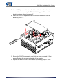
BX-PIB0x Embedded Box System
3. Insert a Phillips screwdriver into the hole on the side of the chassis and
remove the screw securing the PCI slot blanking plate. Remove the
blanking plate as shown by arrow “1”.
4. Insert the PCI/PCIe expansion card into the slot in the riser card as
shown by arrow “2”.
5. Secure the PCI/PCIe expansion card with the screw removed in Step 3
above. Replace the screws on the side of the chassis.
6. Replace the bottom cover of the chassis by reversing Steps 1 and 2
above.
25
BX-PIB0x Embedded Box System
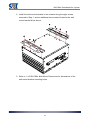
2.6
Installing the Wall Mount Brackets
Optional wall mount brackets are available for the BX-PIB0x and must be
ordered separately.
1. Turn the chassis upside down so the bottom is facing upwards. Remove
the screws securing the four rubber feet and the four screws on the
sides of the bottom cover of the chassis as shown.
26
BX-PIB0x Embedded Box System
2. Install the wall mount brackets to the chassis using the eight screws
removed in Step 1, and an additional two screws included in the wall
mount bracket kit as shown.
3. Refer to 1.4.3 BX-PIB0x Wall Mount Dimensions for dimensions of the
wall mount bracket mounting holes.
27
BX-PIB0x Embedded Box System
2.7
Driver Installation
The drivers for the BX-PIB0x can be found on the driver DVD included with the
system.
Install the following drivers in the order listed.
1.
2.
3.
4.
5.
6.
7.
8.
9.
Chipset
.NET Framework
Graphics
Audio
LAN
Management Engine
USB 3.0
Intel® Rapid Start Technology
Intel® Rapid Storage Technology
28
BX-PIB0x Embedded Box System
3. Connectors & Jumpers
3.1
Power Connector
+9V ~ +36V DC wide range power input - 1x3 terminal block connector
3.2
Pin
Signal
1
GND
2
CH_GND_1
3
DC IN
1
2
3
External Reset Connector
External reset - 1x2 terminal block connector
3.3
Pin
Signal
1
RESETJ
2
GND
1
2
External Power Switch Connector
External power switch - 1x2 terminal block connector
3.4
Pin
Signal
1
PWRBTNJ
2
GND
1
2
Keyboard & Mouse Connectors
Pin
Signal
Pin
Signal
1
KB_DATA
7
MS_DATA
2
NC
8
NC
3
GND
9
GND
4
+5V
10
+5V
5
KB_CLK
11
MS_CLK
6
NC
12
NC
29
BX-PIB0x Embedded Box System
3.5
COM1-4 (RS-232/422/485, BIOS Selectable)
3.5.1
COM1-4 in RS-232 Mode
Pin
Signal
Pin
Signal
1
DCD, Data Carrier Detect
6
DSR, Data Set Ready
2
RXD, Receive Data
7
RTS, Ready To Send
3
TXD, Transmit Data
8
CTS, Clear To Send
4
DTR, Data Terminal Ready
9
RI, Ring Indicator
5
GND, Ground
3.5.2
COM1-4 in RS-422 Mode
Pin
Signal
Pin
Signal
1
TXD-, Transmit Data
6
NA
2
RXD+, Receive Data
7
NA
3
TXD+, Transmit Data
8
NA
4
RXD-, Receive Data
9
NA
5
NA
3.5.3
COM1-4 in RS-485 Mode
Pin
Signal
Pin
Signal
1
TXD+, Transmit Data
6
NA
2
TXD-, Transmit Data
7
NA
3
NA
8
NA
4
NA
9
NA
5
NA
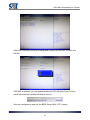
3.5.4
COM1-4 RS-232/422/485 Mode Selection
To set the COM mode, boot the system into BIOS Setup Utility and select
Advanced > F81866 Super IO configuration. You will see the following
screen.
30
BX-PIB0x Embedded Box System
Select the COM port you wish to setup and choose from RS-232, RS-422 and
RS-485.
If RS-485 is selected, you can enable/disable the RS-485 Auto Flow Function
which automatically handles half-duplex control.
Save the configuration and exit the BIOS Setup Utility ("F4" hotkey).
31
BX-PIB0x Embedded Box System
3.6
VGA Connector
15-pin D-sub Female Connector
Pin
Signal
Pin
Signal
1
VGA_RED
9
VCC
2
VGA_GRN
10
GND
3
VGA_BLU
11
NC
4
NC
12
VGA_DDC_DAT
5
GND
13
VGA_HSYNC
6
GND
14
VGA_VSYNC
7
GND
15
VGA_DCC_CLK
8
GND
3.7
GPIO Connector
Pin
Signal
Pin
Signal
1
DIO_PH_IN0
6
DIO_PH_OUT0
2
DIO_PH_IN1
7
DIO_PH_OUT1
3
DIO_PH_IN2
8
DIO_PH_OUT2
4
DIO_PH_IN3
9
DIO_PH_OUT3
5
5V & 12V
3.8
DisplayPort Connector
Pin
Signal
Pin
Signal
1
CN_DP0_P
2
Ground
3
CN_DP0_N
4
CN_DP1_P
5
Ground
6
CN_DP1_N
7
CN_DP2_P
8
Ground
9
CN_DP2_N
10
CN_DP3_P
11
Ground
12
CN_DP3_N
13
CN_CAD-L
14
CN_CEC
15
CN_AUX_P
16
Ground
17
CN_AUX_N
18
DDP_HPD
19
Ground
20
P3V3
32
19
20
1
2
BX-PIB0x Embedded Box System
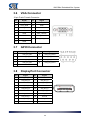
3.9
HDMI Connector
Pin
Signal
Pin
Signal
1
HDMI_TX2_DP_B
2
GND
3
HDMI_TX2_DN_B
4
HDMI_TX1_DP_B
5
GND
6
HDMI_TX1_DN_B
7
HDMI_TX0_DP_B
8
GND
9
HDMI_TX0_DN_B
10
HDMI_CLK_DP_B
11
GND
12
HDMI_CLK_DN_B
13
NC
14
NC
15
HDMI_SCLDDC_B
16
HDMI_SDADDC_B
17
GND
18
+5V
19
1
18
2
3.10 USB 3.0 Connectors
Pin
Signal
Pin
Signal
1
USB +5V
5
USB_SSRX-
2
USB_D-
6
USB_SSRX+
3
USB_D+
7
GND_DRAIN
4
GND
8
USB_SSTX-
9
USB_SSTX+
3.11 USB 2.0 Connectors
Pin
Signal
1
USB +5V
2
USB_D-
3
USB_D+
4
GND
1
33
2
3
4
BX-PIB0x Embedded Box System
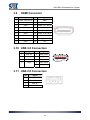
3.12 Front Audio Jacks
Pin
Signal
Blue
Line-In
Green
Line-Out
Pink
Mic-In
3.13 LAN Connectors
Pin
Signal
Pin
Signal
1
MDI0+
5
MDI2-
2
MDI0-
6
MDI1-
3
MDI1+
7
MDI3+
4
MDI2+
8
MDI3-
A
Active LED
B
10 LAN LED (OFF)
(Yellow)
100 LAN LED (Green)
1000 LAN LED (Orange)
3.14 Mini-PCIe Connectors
34
BX-PIB0x Embedded Box System
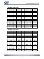
3.14.1 Mini-PCIe (CN22)
Pin
Signal
Pin
Signal
Pin
Signal
Pin
Signal
1
WAKE0J
15
GND
29
GND
43
N/A
2
+3.3V
16
N/A
30
SMB_CLK
44
LED_WLANJ
3
N/A
17
N/A
31
PCIE4_TXN
45
N/A
4
GND
18
GND
32
SMB_DAT
46
LED_WPANJ
5
N/A
19
N/A
33
PCIE4_TXP
47
N/A
6
+1.5V
20
N/A
34
GND
48
+1.5V
7
P3V3
21
GND
35
GND
49
N/A
8
N/A
22
MINI_RST
36
USB6N
50
GND
9
GND
23
PCIE4_RXN
37
N/A
51
N/A
10
N/A
24
3V3SB
38
USB6P
52
+3.3V
11
PCIE0_CLK_N
25
PCIE4_RXP
39
N/A
12
N/A
26
GND
40
GND
13
PCIE0_CLK_P
27
GND
41
N/A
14
N/A
28
+1.5V
42
LED_WWANJ
3.14.2 Mini-PCIe (CN23)
Pin
Signal
Pin
Signal
Pin
Signal
Pin
Signal
1
WAKE0J
15
GND
29
GND
43
N/A
2
+3.3V
16
UIM_VPP
30
SMB_CLK
44
P3V3
3
N/A
17
N/A
31
PCIE5_TXN
45
N/A
4
GND
18
GND
32
SMB_DAT
46
N/A
5
N/A
19
N/A
33
PCIE5_TXP
47
N/A
6
+1.5V
20
N/A
34
GND
48
+1.5V
7
P3V3
21
GND
35
GND
49
N/A
8
UIM_PWR
22
MINI_RST
36
USB7N
50
GND
9
GND
23
PCIE5_RXN
37
N/A
51
N/A
10
UIM_DATA
24
3V3
38
USB7P
52
+3.3V
11
PCIE2_CLK_N
25
PCIE5_RXP
39
N/A
12
UIM_CLK
26
GND
40
GND
13
PCIE2_CLK_P
27
GND
41
N/A
14
UIM_RST
28
+1.5V
42
N/A
35
BX-PIB0x Embedded Box System
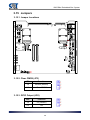
3.15 Jumpers
3.15.1 Jumper Locations
JP6
JP3
JP7
JP8
3.15.2 Clear CMOS (JP3)
JP3
Function
1-2
Normal (default)
2-3
Clear CMOS
3.15.3 GPIO Output (JP6)
JP6
Function
1-2
5V (default)
2-3
12V
36
BX-PIB0x Embedded Box System
3.15.4 BIOS Module Selection (JP7, JP8)
JP7
(BIOS_DIS0#)
JP8
(BIOS_DIS1#)
Function
1-2
1-2
Module SPI (default)
2-3
1-2
N/A
1-2
2-3
Carrier SPI
2-3
2-3
Module SPI 1
37
BX-PIB0x Embedded Box System
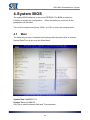
4. System BIOS
The system BIOS software is stored on EEPROM. The BIOS provides an
interface to modify the configuration. When the battery is removed, all the
parameters will be reset.
Turn on the computer and press <DEL> or <F2> to enter the setup screens.
4.1
Main
The Main setup screen is showed as following when the setup utility is entered.
System Date/Time is set up in the Main Menu.
System Date: MM/DD/YYYY
System Time: HH:MM:SS
Use Tab to switch between Date and Time elements.
38
BX-PIB0x Embedded Box System
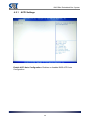
4.2
Advanced
39
BX-PIB0x Embedded Box System
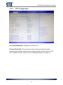
4.2.1
ACPI Settings
Enable ACPI Auto Configuration: Enables or disables BIOS ACPI Auto
Configuration.
40
BX-PIB0x Embedded Box System
4.2.2
CPU Configuration
Limit CPUID Maximum: Disabled for Windows XP.
Execute Disable Bit: XP can prevent certain classes of malicious buffer
overflow attacks when combined with a supporting OS (Windows Server 2003
SP1, Windows XP SP2, SusE Linux 9.2, RedHat Enterprise 3 Update 3.)
41
BX-PIB0x Embedded Box System
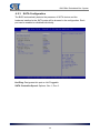
4.2.3
SATA Configuration
The BIOS automatically detects the presence of SATA device and the
hardware installed in the SATA ports will be showed in the configuration. Each
port can be enabled or disabled individually.
Hot Plug: Designates this port as Hot Pluggable.
SATA Controller Speed: Options: Gen 1, Gen 2.
42
BX-PIB0x Embedded Box System
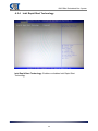
4.2.4
Intel Rapid Start Technology
Intel Rapid Start Technology: Enables or disables Intel Rapid Start
Technology.
43
BX-PIB0x Embedded Box System
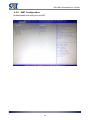
4.2.5
PCH-FW Configuration
Displays the firmware information.
44
BX-PIB0x Embedded Box System
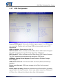
4.2.6
AMT Configuration
Enable/disable and configure Intel AMT.
45
BX-PIB0x Embedded Box System
4.2.7
USB Configuration
Legacy USB Support: Auto option disables legacy support if no USB devices
are connected. Disable option will keep USB devices available only for EFI
applications.
USB 3.0 Support: Enable/disable USB 3.0.
XHCI Hand-off: This is a workaround for OSes without XHCI hand-off support.
The XHCI ownership change should be claimed by XHCI driver.
EHCI Hand-off: This is a workaround for OSes without EHCI hand-off support.
The EHCI ownership change should be claimed by EHCI driver.
USB Mass Storage Driver Support: Enable/Disable USB Mass Storage
Driver Support.
USB transfer time-out: The time-out value for Control, Bulk, and Interrupt
transfers.
Device reset time-out: USB mass storage device Start Unit command
time-out.
Device power-up delay: Maximum time the device will take before it properly
reports itself to the Host Controller. “Auto” uses default value: for a Root port it
is 100ms, for a Hub port the delay is taken from Hub descriptor.
46
BX-PIB0x Embedded Box System
4.2.8
Hardware Monitor
CPU and memory health status information.
47
BX-PIB0x Embedded Box System
4.2.9
F81801 H/W Monitor
Smart Fan Function: Enable/disable Smart Fan.
4.2.9.1
Smart Fan Configuration
Smart Fan 1 Mode: Select CPU Smart Fan 1 Mode.
48
BX-PIB0x Embedded Box System
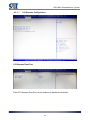
4.2.10 F81866 Super IO Configuration
Enable/disable and configure the serial ports.
49
BX-PIB0x Embedded Box System
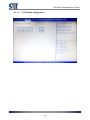
4.2.10.1
Serial Port Configuration
Select the COM port you wish to setup and choose from RS-232, RS-422 and
RS-485.
If RS-485 is selected, you can enable/disable the RS-485 Auto Flow Function
which automatically handles half-duplex control.
50
BX-PIB0x Embedded Box System
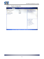
4.2.11 F81866 H/W Monitor
System health information and Smart Fan configuration.
4.2.11.1
Smart Fan Mode Configuration
Smart Fan Control: Select System Smart Fan Mode.
51
BX-PIB0x Embedded Box System
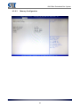
4.2.12 Serial Port Console Redirection
Serial port console redirection settings.
52
BX-PIB0x Embedded Box System
4.2.13 CPU PPM Configuration
Intel SpeedStep settings.
53
BX-PIB0x Embedded Box System
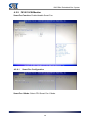
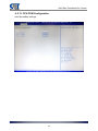
4.2.14 Intel I210 Gigabit Network Connection
4.2.14.1
NIC Configuration
54
BX-PIB0x Embedded Box System
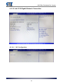
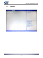
4.3
Chipset
55
BX-PIB0x Embedded Box System
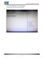
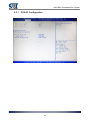
4.3.1
PCH-IO Configuration
56
BX-PIB0x Embedded Box System
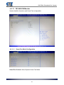
4.3.1.1
PCI Express Configuration
PCI Express Root Port
Each PCI Express Root Port can be enabled or disabled individually.
57
BX-PIB0x Embedded Box System
4.3.1.2
USB Configuration
58
BX-PIB0x Embedded Box System
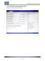
4.3.1.3
PCH Azalia Configuration
59
BX-PIB0x Embedded Box System
4.3.2
System Agent Configuration
60
BX-PIB0x Embedded Box System
4.3.2.1
Graphics Configuration
61
BX-PIB0x Embedded Box System
LCD Control
62
BX-PIB0x Embedded Box System
4.3.2.2
NB PCIe Configuration
63
BX-PIB0x Embedded Box System
4.3.2.3
Memory Configuration
64
BX-PIB0x Embedded Box System
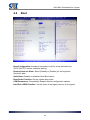
4.4
Boot
Boot Configuration: Number of seconds to wait for setup activation key.
65535 (0xFFFF) means indefinite waiting.
Bootup NumLock State: Select [Enable] or [Disable] for the keyboard
NumLock state.
Quiet Boot: Enables or disables Quiet Boot option.
Boot Order Priorities: Set the system boot order.
CSM Parameters: Compatibility Support Module configuration options.
Hard Drive BBS Priorities: Set the order of the legacy devices in this group.
65
BX-PIB0x Embedded Box System
4.4.1.1
CSM16 Parameters
OpROM execution, boot options filter, etc.
GateA20 Active:
[Upon Request] – GA20 can be disabled using BIOS services.
[Always] – do not allow disabling GA20; this option is useful wen any RT
code is executed above 1MB.
Option ROM Message: Set display mode [Force BIOS] or [Keep Current] for
Option ROM.
4.4.1.2
CSM Parameters
Launch CSM: This option controls if CSM will be launched always or never.
Boot option filer: This option controls what devices system can boot to [UEFI
and Legacy], [Legacy only] or [UEFI only].
Launch PXE OpROM policy: This controls the execution of UEFI and Legacy
PXE OpROM, [Do not launch], [UEFI only] or [Legacy only].
Launch Storage OpROM policy: This controls the execution of UEFI and
Legacy Storage OpROM, [Do not launch], [UEFI only] or [Legacy only].
Launch Video OpROM policy: This controls the execution of UEFI and
Legacy Video OpROM, [Do not launch], [UEFI only] or [Legacy only].
66
BX-PIB0x Embedded Box System
Other PCI device ROM priority: For PCI devices other than Network, Mass
storage or Video defines which OpROM to launch, [UEFI OpROM] or [Legacy
OpROM].
4.4.1.3
Hard Drive BBS Priorities
67
BX-PIB0x Embedded Box System
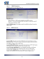
4.5
Security
Administrator’s and User’s passwords could be set.
If ONLY the Administrator’s password is set, then this only limits access to
Setup and is only asked for when entering Setup. If ONLY the User’s password
is set, then this is a power on password and must be entered to boot or enter
Setup. In Setup, the user will have administrator rights. The minimum length of
the password is 3 and the maximum length is 20.
68
BX-PIB0x Embedded Box System
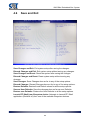
4.6
Save and Exit
Save Changes and Exit: Exit system setup after saving the changes.
Discard Changes and Exit: Exit system setup without saving any changes.
Save Changes and Reset: Reset the system after saving the changes.
Discard Changes and Reset: Reset system setup without saving any
changes.
Save Changes: Save Changes done so far to any of the setup options.
Discard Changes: Discard Changes done so far to any of the setup options.
Restore Defaults: Restore/Load Default values for all the setup options.
Save as User Defaults: Save the changes done so far as user Defaults.
Restore user Defaults: Restore the User Defaults to all the setup options.
Launch EFI Shell from filesystem device: Attempts to Launch EFI Shell
application (Shellx64.efi) from one of the available filesystem devices.
69
BX-PIB0x Embedded Box System
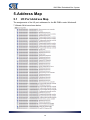
5. Address Map
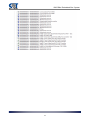
5.1
I/O Port Address Map
The assignments of the I/O port addresses for the BX-PIB0x under Windows®
7 Ultimate 64-bit are shown below.
70
BX-PIB0x Embedded Box System
71
BX-PIB0x Embedded Box System
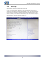
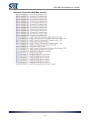
5.2
Interrupt Controller (IRQ) Map
The interrupt controller map for the BX-PIB0x under Windows® 7 Ultimate
64-bit is shown below.
72
BX-PIB0x Embedded Box System
Interrupt Controller (IRQ) Map (cont'd)
73
BX-PIB0x Embedded Box System
Interrupt Controller (IRQ) Map (cont'd)
74
BX-PIB0x Embedded Box System
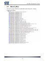
5.3
Memory Map
The memory map of DRAM for the BX-PIB0x under Windows® 7 Ultimate
64-bit is shown below.
75