1
1st PRINTING March 99
STD VERSION
OWNER’S MANUAL
SEGA ENTERPRISES, INC. USA
MANUAL NO. 4201-6468-01
Warranty
Your new Sega Product is covered for a period of 90 days from the date of shipment. This certifies
that the Printed Circuit Boards, Power Supplies and Monitor are to be free of defects in workmanship or materials under normal operating conditions. This also certifies that all Interactive Control
Assemblies are to be free from defects in workmanship and materials under normal operating conditions. No other product in this machine is hereby covered.
Sellers sole liability in the event a warranted part described above fails shall be, at its option, to
replace or repair the defective part during the warranty period. For Warranty claims, contact your
Sega Distributor.
Should the Seller determine, by inspection that the product was caused by Accident, Misuse, Neglect, Alteration, Improper Repair, Installation or Testing, the warranty offered will be null and void.
Under no circumstances is the Seller responsible for any loss of profits, loss of use, or other damages.
This shall be the exclusive written Warranty of the original purchaser expressed in lieu of all other
warranties expressed or implied. Under no circumstance shall it extend beyond the period of time
listed above.
VISIT OUR WEBSITE!
TABLE OF CONTENTS
INTRODUCTION OF THE OWNERS MANUAL
GENERAL PRECAUTIONS
1. PRECAUTIONS TO BE HEEDED FOR OPERATION
2. NAME OF PARTS
3. ACCESSORIES
4. ASSEMBLY AND INSTALLATION
5. PRECAUTIONS TO BE HEEDED WHEN MOVING MACHINE
6. CONTENTS OF GAME
7. EXPLANATION OF TEST AND DATA DISPLAY
7-1 SWITCH UNIT AND COIN METER
7-2 SYSTEM TEST MODE
7-3 GAME TEST MODE
7-4 INPUT TEST
7-5 OUTPUT TEST
7-6 SOUND TEST
7-7 C.R.T. TEST
7-8 VOLUME SETTING
7-9 GAME ASSIGNMENTS
7-10 COIN ASSIGNMENTS
7-11 BOOKKEEPING
7-12 BACKUP DATA CLEAR
8. HANDLE MECHA
8-1 REMOVING THE CONTROL PANEL
8-2 REPLACING AND ADJUSTING THE HANDLE’S VR
8-3 GREASING
9. SHIFT LEVER
9-1 REMOVING THE SHIFT LEVER
9-2 SWITCH REPLACEMENT
10. ACCEL & BRAKE
10-1 ADJUSTING AND REPLACING THE VR
10-2 GREASING TO FOOT BRAKE AND ACCEL
11. COIN SELECTOR
12. MONITOR
13. REPLACEMENT OF FLUORESCENT LAMP
13-1 REPLACEMENT OF FLUORESCENT LAMP
14. PERIODIC INSPECTION TABLE
15. TROUBLESHOOTING
16. GAME BOARD
16-1 REMOVING THE GAME BOARD
16-2 REPLACMENT OF FUSE
16-3 COMPOSITION OF THE GAME BOARD
18. DESIGN RELATED PARTS
19. PARTS LIST
20. WIRING DIAGRAMS
1
2~3
4~5
6
7~8
9~15
16
17~19
20~30
21
22
22
23
23
24
24
25
26
27~29
30
30
31~33
31
32
33
34~35
34
35
36~37
36~37
37
38~40
41~43
44
44
45
46
47~49
47
48
49
50
51~78
XXX
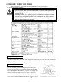
SPECIFICATIONS
Installation space:
68 in.(L) x 41 in.(W)
Height:
84 in.
Weight:
Approx. 550 lbs.
Power maximum current:
3.5 Amp AC 120V 60 Hz
MONITOR:
29” NANAO MONITOR
INTRODUCTION OF THE OWNERS MANUAL
SEGA ENTERPRISES, LTD., has for more than 30 years been supplying various innovative and
popular amusement products to the world market. This Owners Manual is intended to provide
detailed descriptions together with all the necessary installation, game settings and parts ordering
information related to CRAZY TAXI, a new SEGA product.
This manual is intended for those who have knowledge of electricity and technical expertise, especially in ICs, CRTs, microprocessors, and circuit boards. Read this manual carefully to acquire
sufficient knowledge before working on the machine. Should there be a malfunction, non-technical
personnel should under no circumstances touch the interior system. Should the need arise, contact
our main office, or the closest branch office listed below.
SEGA ENTERPRISES, INC. (USA)
Customer Service
45133 Industrial Drive
Fremont, CA 94538
Phone 650-632-7580
Fax 650-632-7594
7:30 am - 4:00 pm, Pacific Standard Time
Monday thru Friday
1
General Precautions
Follow Instructions: All operating and use instructions should be followed.
Attachments: Do not use attachments not recommended by the product manufacturer as they may cause hazards.
Accessories: Do not place this product on an unstable cart, stand, tripod, bracket, or table. The product may fall,
causing serious injury to a child or adult, and serious damage to the product. Use only with a cart, stand, tripod, bracket, or
table recommended by the manufacturer, or sold with the product. Any mounting of the product should follow the
manufacturer’s instructions, and should use only mounting accessories recommended by the manufacturer.
Moving the Product: This product should be moved with care. Quick stops, excessive force, and uneven surfaces
may cause the product to overturn.
Ventilation: Slots and openings in the cabinet are provided for ventilation, to ensure reliable operation of the product
and to protect it from overheating; these openings must not be blocked or covered. The openings should never be blocked
by placing the product in a built-in installation such as a bookcase or rack unless proper ventilation is provided or the
manufacturer’s instructions have been adhered to.
Power Sources: This product should be operated only from the type of power source indicated on the marking label.
If you are not sure of the type of power supply to your location, consult your local power company. For products intended
to operate from battery power or other sources, refer to the operating instructions.
Grounding or Polarization: This product is equipped with a three-wire grounding-type plug, a plug having a third
(grounding) pin. This plug will only fit into a grounding-type power outlet. This is a safety feature. If you are unable to
insert the plug into the outlet, contact your electrician to replace your obsolete outlet. Do not defeat the safety purpose of the
grounding-type plug.
Power Cord Protection: Power-supply cords should be routed so that they are not likely to be walked on or pinched
by items placed upon or against them, paying particular attention to cords at plugs, convenience receptacles, and the point
where they exit from the product.
Overloading: Do not overload wall outlets, extension cords, or integral convenience receptacles as this can result in
a risk of fire or electric shock.
Object and Liquid Entry: Never push objects of any kind into this product through openings as they may touch
dangerous voltage points or short-out parts that could result in a fire or electric shock. Never spill liquid of any kind on the
product.
Servicing: Do not attempt to service this product yourself as opening or removing covers may expose you to dangerous voltage or other hazards. Refer all servicing to qualified service personnel.
Damage Requiring Service: Unplug this product from the wall outlet and refer servicing to qualified service personnel under the following conditions:
a) If the power cord or plug is damaged;
b) If liquid has been spilled, or objects have fallen into the product;
c) If the product has been exposed to rain or water;
d) If the product does not operate normally when following the operating instructions. Adjust only those controls that
are explained in the operating instructions. An improper adjustment of other controls may result in damage and will
often require extensive work by a qualified technician to restore the product to its normal operation;
e) If the product has been dropped or damaged in any way;
f) When the product exhibits a distinct change in performance; this indicates a need for service.
Replacement Parts: When replacement parts are required, be sure the service technician has used replacements parts
specified by the manufacturer or that have the same characteristics as the original part. Unauthorized substitutions may
result in fire, electric shock, or other hazards.
2
Safety Check: Upon completion of any service or repairs to this product, ask the service technician to perform safety
checks to determine that the product is in proper operating condition.
Heat: The product should be situated away from heat sources such as radiators, heat registers, stoves, or other products (including amplifiers) that produce heat.
Lithium Battery- Dispose of batteries only in accordance with the battery manufacturer’s recommendations.
Do not dispose in an open flame condition, since the battery may explode.
Cleaning: When cleaning the monitor glass, use water or glass cleaner and a soft cloth. Do not apply chemicals such
as benzine, thinner, etc.
Location: This an indoor game machine, DO NOT install it outside. To ensure proper usage, avoid installing indoors
in the places mentioned below:
• Places subject to rain/water leakage, or condensation due to humidity;
• In close proximity to a potential wet area;
• Locations receiving direct sunlight;
• Places close to heating units or hot air;
•In the vicinity of highly inflammable/volatile chemicals or hazardous matter;
• On sloped surfaces;
• In the vicinity of emergency response facilities such as fire exits and fire extinguishers;
• Places subject to any type of violent impact;
• Dusty places.
INSTALLATION PRECAUTIONS
• Verify the amperage of the branch circuit outlet before plugging in the power plug. Do not overload the circuit.
• Avoid using an extension cord. If one is required, use an extension cord of type SJT, 16/3 AWG
rated min. 120 VAC, 7A.
• Moving this unit requires a minimum clearance (of doors, etc.) of 32” (W) by 77” (H).
• For the operation of this machine, secure a minimum area of 32” (W) by 42”(D).
REGULATORY APPROVALS
This game has been tested and found to comply with the Federal Communications Commission Rules.
This device complies with Part 15 of the FCC Rules. Operation is subject to the following two conditions: (1) This
device may not cause harmful interference, and (2) this device must accept any interference received, including interference
that may cause undesired operation.
This game has been tested and listed by Underwriters Laboratories, Inc., to ANSI/UL22.
LISTED
UL
5K92
®
AMUSEMENT MACHINE
3
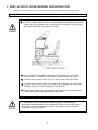
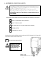
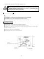
1 . PRECAUTIONS TO BE HEEDED FOR OPERATION
In order to prevent accidents, be sure to comply with the following points before and during operation.
PRECAUTIONS TO BE HEEDED FOR OPERATION BEFORE STARTING THE OPERATION
In order to avoid accidents, check the following before starting the operation:
Check if all of the adjusters are in contact with the surface. If they are not,
the cabinet can move and cause an accident.
Do not climb on the product. Climbing on the product can cause falling
down accidents. To check the top portion of the product, use a step.
To avoid electric shock, check to see if door & cover parts are closed.
To avoid electric shock, short circuit and or parts damage, do not put the
following items on or in the periphery of the product:
Flower vases, flower pots, cups, water tanks, cosmetics, and receptacles/
containers/vessels containing chemicals and water.
To avoid injury, be sure to provide sufficient space by considering the
potentially crowded situation at the installation location. Insufficient installation space can cause the player to come into contact with or hit others
and result in injury or trouble.
4
PRECAUTIONS TO BE HEEDED DURING OPERATION
To avoid injury and accidents, those who fall under the following catagories are not
allowed to play the game:
* Intoxicated persons
* Those who have high blood pressure or heart problems.
* Those who have experienced muscle convulsion or loss of consciousness when playing
video games, etc.
* Persons susceptible to motion sickness.
* Persons whose acts runs counter to the products warning displays.
* Instruct those who wear high-heeled shoes to refrain from
playing the game by explaining that playing the game with highheeled shoes is very dangerous and likely to cause a potentially
hazardous situation.
To avoid electric shock and short circuit, do not allow customers to put hands and fingers
or extraneous matter in openings of the product or small openings in or around doors.
To avoid electric shock and short circuit, do not allow the customers to unplug the power
plug without a justifiable reason.
Although this product has the accident preventive covering attached to potentially hazardous places where hand and fingers could be caught, small children are unable to perceive
hazards. Use care so that small children do not come close to the product when in play.
Immediately stop such violent acts as hitting and kicking the product. Such violent acts can
cause parts damage and/or falling down, resulting in injury due to fragments and falling
down.
5
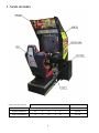
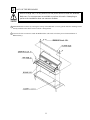
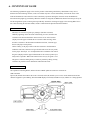
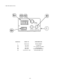
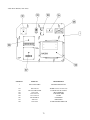
2 . NAME OF PARTS
GAME SPECIFICATIONS
WIDTH in.
LENGTH in.
HEIGHT in.
WEIGHT lbs.
All measurements are and rounded UP
DURING SHIPPING
45”
X
70”
X
84”
~ 600 LBS.
WHEN ASSEMBLED
39”
X
65”
X
80”
550 LBS.
6
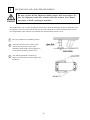
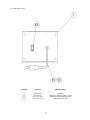
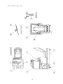
3 . ACCESSORIES
7
THE SHIPMENT METHOD DESCRIBED BELOW ONLY
APPLIES TO ‘MODEL 3’ BOARDS CONTAINED IN THE
FOLLOWING GAMES:
LOST WORLD, VIRTUA FIGHTER 3, SUPER GT, SEGA BASS FISHING, STRIKER 2
HARLEY DAVIDSON, RALLY 2, DAYTONA 2, DIRT DEVILS, HOUSE OF THE DEAD 2,
OCEAN HUNTER, STAR WARS TRILOGY, ZOMBIE REVENGE, CRAZY TAXI
!!NEVER SHIP MODEL 3 / NAOMI GAME
BOARDS OUTSIDE OF CAGE!!
CARTON BOX
601-8928 (1)
Used for transporting the GAME BOARD.
{SUPPLIED WITH YOUR GAME}
DO NOT SHIP GAME BOARD WITHOUT
THIS BOX AS IT MAY DAMAGE THE GAME
BOARD AND VOID YOUR WARRANTY.
“CHECK SIDE” Display
FILTER BOARD
NO OTHER GAMES BOARDS ARE TO BE SHIPPED IN THE CAGE AS
THEY MAY BE DAMAGED BEYOND REPAIR. PLEASE SHIP THEM
WITHOUT CAGE PROPERLY PROTECTED DURING SHIPPING.
8
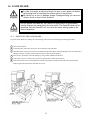
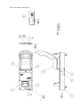
4 . ASSEMBLING AND INSTALLATION
Assembling should be performed as per this manual. Since this is a
complex machine, erroneous assembling may cause damage to the
machine, or malfunctioning to occur.
When assembling, be sure to perform work by plural persons.
Depending on the assembly work, there are some cases in which
performing the work by a single person can cause personal injury or
parts damage.
When carrying out the assembly work, follow the procedure in the following 5-item sequence:
1
ASSY OF THE REAR CABI (COCKPIT)
2
ASSY OF BILLBOARD
3
SECURING IN PLACE (ADJUSTER ADJUSTMENT)
4
POWER SUPPLY
5
ASSEMBLING CHECK
Note that the tools such as a phillips screwdriver and wrench for M16 hexagon bolt w/24 mm width
across flats are required for the assembly work.
1
ASSY OF REAR CABI (COCKPIT)
Permanantly tightening
the hex bolts should
not be completed until
the leg levelers are
adjusted properly.
9
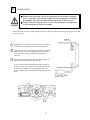
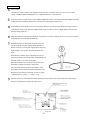
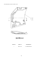
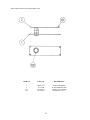
1
Install the coin chute tower on the Right-hand side of cabinet. Open the coin chute door and the cashbox door to
secure with the 4 hexagon bolts from inside the doors. Please note that the Coin Chute tower is NOT mounted
on the Left-hand side as shown above.
NOTE: ON SEGA’s CRAZY TAXI GAME THERE IS NOT TWO COCKPITS SIDE BY SIDE AS PICTURED ABOVE.
THE GAME HAS ONLY ONE COCKPIT AND THE COIN TOWER WILL MOUNT ON THE RIGHT SIDE AS YOU
FACE THE CABINET..
10
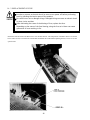
2
ASSY OF THE BILLBOARD
Due to its large size, it is very difficult for one person alone to install the billboard,
Make sure 2 or more persons are available to perform this work. Attempting to
perform the installation alone can cause an accident.
1 Mount Billboard on cabinet by ensuring the front lip of the Billboard is securely placed under the mounting bracket
already installed on the cabinet. Fasten with the 3 hexagon bolts.
2 Connect all of the 4 connectors inside the Billboard box (This needs to be done prior to final installation of
Billboard Assy).
11
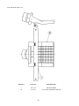
3
SECURING IN PLACE (ADJUSTER ADJUSTMENT)
Be sure to have all the Adjusters make contact with the surface. Unless the Adjusters come into contact with the surface, the Cabinet
can move of itself, causing an accident.
This machine has 4 each of casters and adjusters (shown below). When the installation position is determined, cause
the adjusters to come into contact with the floor directly, make adjustments in a manner so that the casters will be
raised approximately 5mm. from the floor and make sure that the machine position is level.
1
Move the machine to the installation position.
2
Cause all of the leg levelers to make contact
with the floor. By using a wrench, make
adjustments in the height of the leg adjusters to
ensure that the machine's position is level.
3
After making adjustments, fasten the leg
adjuster nut upward and secure the height of the
leg adjuster.
12
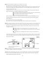
4
POWER SUPPLY
Ensure that the power cord is not exposed on the surface (passage,
etc.). If exposed, they can be caught and are susceptible to damage.
If damaged, the cord can cause an electric shock or short circuit.
Ensure that the wiring position is not in the customer's passage way
or the wiring has protective covering.
Connect the game to the power supply and turn on power to the game. Before connecting power supply be sure that
power switch is off
1 Turning the AC unit’s main switch on will cause the machine
to start the power check and network check automatically.
2 In the Power On check, the steering wheel turns left and right,
and then returns to the centering position and stops. In this
check, the values of the VR inside the control panel are
corrected.
3 Until this check is finished, and the steering wheel stops, do
not touch the steering wheel or play the game.
If you do, the steering reaction during the game (reaction at
the time of course-out or crash) can not be obtained correctly.
In the case of an abnormal reaction during the game, turn
power on again from the beginning and complete the power on
check.
13
5
ASSEMBLING CHECK
The TEST MENU allows for each part of the cabinet to be checked, the Monitor to be adjusted, and the coin and game
related various functions to be performed.
Selecting the MEMORY TEST on the test mode menu screen causes the on-board memory to be tested automatically.
The game board is satisfactory if the display beside each IC No. shows GOOD.
Selecting the INPUT TEST on the Test Mode menu screen
causes the screen (on Which each switch adnV.R. are tested)
to be displayed. Press each switch. For the coin switch test,
insert a coin from the coin inlet with the coin chute door
being open. If the display beside each switch indicates
“ON”, the switch and wiring connections are satisfactory.
Check the display of V.R. value for steering wheel and
accelerator & brake. If the V.R. values are not satisfactory,
make adjustments as neccesary.
In the OUTPUT TEST mode, carry out lamp test to ensure
that each lamp lights up satisfactory.
14
SOUND TEST
VOICE
EFFECT
B.G.M.
In the TEST mode, selecting SOUND TEST causes the
screen, on which sound related BD and wiring connections are tested, to be displayed. Be sure to check if the
sound is satisfactorily emitted from each of speaker and
the sound volume is appropriate.
>EXIT
SELECT WITH SERVICE BUTTON AND
PRESS TEST BUTTON TO EXIT
C.R.T. TEST 1/2
12345678901234567890123456789012123456789012
12345678901234567890123456789012123456789012
12345678901234567890123456789012123456789012
12345678901234567890123456789012123456789012
12345678901234567890123456789012123456789012
12345678901234567890123456789012123456789012
12345678901234567890123456789012123456789012
12345678901234567890123456789012123456789012
12345678901234567890123456789012123456789012
RED
12345678901234567890123456789012123456789012
12345678901234567890123456789012123456789012
123456789012345678901234567890121234567
123456789012345678901234567890121234567
123456789012345678901234567890121234567
123456789012345678901234567890121234567
123456789012345678901234567890121234567
123456789012345678901234567890121234567
GREEN
123456789012345678901234567890121234567
123456789012345678901234567890121234567
123456789012345678901234567890121234567
123456789012345678901234567890121234567
1234567890123456789012345678
123456789012345678901234567890121234567
1234567890123456789012345678
1234567890123456789012345678
1234567890123456789012345678
BLUE
1234567890123456789012345678
1234567890123456789012345678
1234567890123456789012345678
1234567890123456789012345678
In the TEST mode menu, selecting C.R.T. TEST allows the
screen (on which the projector is tested) to be displayed.
Although the projector adjustments have been made at the
same time of shipment from the factory, color deviation,
etc., may occur due to the effect caused by geomagnitism,
the location building’s steel frames and other game machines in the periphery. By watching the test mode screen,
make judgement as to whether an adjustment is needed. If it
is neccessary, adjust the projector by refering to Section 9.
WHITE
PRESS TEST BUTTON TO CONTINUE
1234567890123456789012345678
1234567890123456789012345678
1234567890123456789012345678
1234567890123456789012345678
1234567890123456789012345678
1234567890123456789012345678
1234567890123456789012345678
1234567890123456789012345678
1234567890123456789012345678
1234567890123456789012345678
1234567890123456789012345678
1234567890123456789012345678
1234567890123456789012345678
1234567890123456789012345678
1234567890123456789012345678
1234567890123456789012345678
1234567890123456789012345678
1234567890123456789012345678
1234567890123456789012345678
1234567890123456789012345678
1234567890123456789012345678
1234567890123456789012345678
1234567890123456789012345678
1234567890123456789012345678
1234567890123456789012345678
C.R.T. TEST 2/2
PRESS TEST BUTTON TO CONTINUE
Perform the above inspections also at the time of monthly inspection.
15
5 . PRECATIONS TO BE HEEDED WHEN MOVING THE MACHINE
When moving the machine, be sure to pull out the plug from
the power supply. Moving the machine with the plug as is
inserted can damage the power cord and cause a fire or electric shock.
When moving the machine on the floor, retract the Adjusters
and ensure that Casters make contact with the floor. During
transportation, pay careful attention so that Casters do not
tread power cords. Damaging the power cords can cause an
electric shock and/or short circuit.
When lifting the cabinet, be sure to hold the catch portions or
bottom part. Lifting the cabinet by holding other portions can
damage parts and installation portions, due to the empty
weight of the cabinet, and cause personal injury.
Use care when handling glass made parts. When the glass is damaged, fragments of glass can cause injury
16
6 . CONTENTS OF GAME
The following explanations apply to the case the product is functioning satisfactorily. Should there be any moves
different from the following contents, some sort of faults may have occured. Immediately look into the cause of the
fault and eliminate the cause thereof to ensure satisfactory operation. During the Advertise mode, the Billboard’s
Decoration Lamp lights up periodically. When the machine is energized, the Billboard’s Fluorescent Lamp is always lit.
The Steering Wheel repeats centering action periodically. Automatic centering will apply to the Steering Wheel if it is
not centered. During the Advertise Mode, sound is emitted from the Speaker beside the Monitor.
OUTLINE OF GAME
The Player as a taxi driver picks up a passanger (hereafter customer)
randomly appearing on the the Game Field waiting for a taxi, and takes the
Customer tot he desired destination. Time Limit is set for each Customer
(displayed on the upper left-hand side of Customer while traveling). If the
taxi takes Customer to the destination within the time limit, Customer pays
the fare (the player earns points.).
On the contrary, if the player fails to take the Customer to the destination
within the time limit, Customer will get off and results in no fare (no points)
for the player. The Player is to accomplish the above within the time limit of
the game (displayed on the upper left-hand side of the screen) repetitively as
many times as possible. When time limit becomes zero (0), the game is over.
The game is aimed at earning money as much as possible by taking as many
Customers as possible to their destinations within the time limit.
HOW TO OPERATE
The operation of Steering Wheel, and Accelerator & Brake pedals are similiar to an actual car.
SHIFT LEVER
Input to (D) towards the monitor side to drive forward, and to (R) towards you to reverse. Auto transmission and not
manual is applied to speed shifting. The DR LAMP displays Forward (D) and Reverse (R), whichever is being inputted.
17
HOW TO PLAY
1
Insert a coin.
Coin insertion causes credit(s) to be displayed on the screen. For example, in the case of 2 coins one credit
setting, “INSERT COIN(S) CREDIT(S) 1/2” is displayed when one coin is inserted.
2
Inserting one play worth of coin(s) causes “PRESS START BUTTON” to be displayed and the START BUTTON
to flash. Press the START BUTTON to have the character mode appear on this screen.
3
In the Character Select Mode, select on-screen player character. Turn the Steering Wheel left or right to shift to
each character select mode. Press the START button or step on either of Accel. or Brake pedal to decide on the
character being displayed.
4
While the Character Select Mode is displayed, countdown is executed. Counting down to (0) causes the character
being displayed to be selected automatically.
5
When the character is determined, the game starts. The
Taxi picks up the Customer who has the $ Mark above
him/her. There is a circular mark signifying the Stop Area
in the periphery of Customer. Stop the taxi in the Stop
Area.
When the taxi comletely stops in the Stop Area, the onscreen scene shifts and Customer rides in automatically. At
this time, the taxi is in status not operable.
When the Customer rides in, the neccessary time to the
destination is added to the Game’s Time Limit.
The color of the $ mark represents the distance of the
destination. Green indicates the furthest destination. The
distance becomes shorter sequentially in order of green->yellowish green-->yellow-->-->orange-->red.
6
Take the Customer to the destination. While traveling to the destination, time limit and the arrow showing the
direction of destination are displayed on the screen.
18
6 The following explains as regards how to earn FARE (or score points).
The minimum fare is earned at the time the taxi picks up the Customer.
Basically, the best way to earn FARE is to take the Customer to their destiantion as fast as possible. In other words,
since the time remaining when reaching the destination is converted into FARE, the more remaining time is, the
greater the FARE the player earns.
In addition to the above, receiving a tip is another way of increasing the FARE. The tip awarded for doing something to please the customer is added to the FARE. Details are as follows:
Tip for dodging: Awarded when dodging other (ordinary) car at the very critical moment.
Tip for Jumping: Awarded when the taxi jumps over trailers, etc.
Tips for drifting: Awarded when the taxi drifts.
When awarding tips, coins are sent in a flying motion from the Customer towards the FARE METER. If tips are
consecutively earned, the earning rate increases (in combo) This combo effect resets if the taxi bumps against
another ordinary car.
The combo display appears below the FARE METER.
The Customer’s fare is not added to the TOTAL FARE unless the Customer is taken to the destination.
7 When reaching the destination, drop off the Customer. Stop the taxi within the destination area mark. When the taxi
completely stops within the area, the on-screen shifts to evaluation mode and the customer gets of automatically.
the Customer’s evaluation displayed in characters depends on the remaining seconds of the Customer time when
reaching the destination.
SPEEDY: Display of more remaining time/money converted from time is paid.
NORMAL: Display of normal remaining time/normal amount of money converted from
time paid.
SLOW: Display of less remaining time/less amount of money converted from time is
paid.
After suming up the above, the Customer’s FARE is determined and then the FARE is added to the TOTAL FARE.
After TOTAL FARE calculations, the player ranking is displayed. The ranking is based on the score data of the 99
players played in the past.
8 If the remaining time of the Customer becomes zero, the Customer becomes angry and gets off. At this time, the
Customer’s FARE is not added to the TOTAL FARE.
9 When the Game Time becomes 0, the game is over. The GAME OVER screen appears, with TOTAL EARNED,
evaluation comment and RANKING displayed. If any credit(s) which is one play worth or more remains, the
START LAMP unlit during game will then flash.
19
7 . EXPLANATION OF TEST AND DATA DISPLAY
By operating the switch unit, periodically perform the tests and data check. When installing the machine initially or
collecting cash, or when the machine does not function correctly, perform checking in accordance with the explanations
given in this section. The following shows tests and modes that should be utilized as applicable.
CAUTIONS TO BE HEEDED WHEN USING THE TEST MODE:
In the case where plural machines are linked for communication play, if even one seat enters
the test mode, all of the linked seats will enter the test mode. Therefore, if any one of the
linked machines is in play, use care so as not to use the test mode.
The contents of the setting changes made will not be effective unless the test mode is
finished in the test mode. When the setting is changed, be sure to “EXIT” in the menu mode.
Do not press the TEST BUTTON during network check at the time of turning the power on or
exiting from the test mode. If anyone of the linked machines uses the test mode during
network check, all other Seats will continue network checking. Cause all of the Seats to
reenter the test mode and then have all of the Seats exit from the test mode simultaneously.
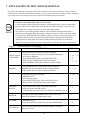
TABLE 7
EXPLANATION OF TEST MODE
ITEMS
DESCRIPTION
When the machine is installed, perform the following:
INSTALLATION 1. Check to see that each setting is as per standard setting made
at the time of shipment.
OF MACHINE
2. In the INPUT TEST mode, check each SW and VR.
3. In the OUTPUT TEST mode, check each of lamps.
4. In the MEMORY TEST mode, check ICs on the IC Board.
MEMORY
P
CONTROL
SYSTEM
Choose MEMORY TEST in the MENU mode to allow the
MEMORY test to be performed. In this test, PROGRAM
RAMs, ROMs, and ICs on the IC Board are checked.
SECTIONS
7 - 10, 7 - 11
7-6
7-7
7 - 3, 7 - 4
7 - 3, 7 - 4
Periodically perform the following:
1. MEMORY TEST
2. Ascertain each setting.
3. In the INPUT TEST mode, test the CONTROL device
4. In the OUTPUT TEST mode, check each of lamps.
7 - 10, 7 - l1
1. In the INPUT TEST mode, check each SW and VR.
2. Adjust or replace each SW and VR.
3. If the problem can not be solved yet, check the CONTROL’s moves.
7-6
MONITOR
In the MONITOR ADJUSTMENT mode, check to see if the
MONITOR adjustment is appropriately made.
IC BOARD
1. MEMORY TEST
2. In the SOUND TEST mode, check the sound related ROMs.
DATA CHECK
Check such data as game play time and histogram to adjust the
difficulty level, etc
20
7-6
7-7
8
12
7-2
7-8
7 - 15
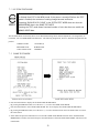
7 - 1 SWITCH UNIT AND COIN METER
Never touch places other than those specified. Touching places not
specified can cause electric shock and short circuit.
Adjust to the optimum sound volume by considering the environmental
requirements of the installation location.
If the COIN METER and the game board are electrically disconnected,
game play is not possible.
Open COIN CHUTE DOOR, and the switch unit shown appears. The function of
each switch is as follows:
SWITCH UNIT
1
SOUND VOLUME
Controls the speaker volume
of the right/left speakers.
2
TEST BUTTON (TEST SW)
For the handling of the TEST BUTTON,
refer to the section on test mode.
3
SERVICE BUTTON (SERVICE SW)
Gives credits without registering on the coin
meter.
21
7 - 2 SYSTEM TEST MODE
The contents of setings chnaged in the TEST mode are stored when the TEST mode
is finished from EXIT in the MENU mode. If the power is turned off before the TEST
mode is finished, the contents of setting chnage become ineffective.
Executing “BACKUP DATA CLEAR” in the SYSTEM TEST MODE does not clear the
BOOKKEEPING data in the GAME TEST MODE.
Entering the TEST mode clears fractional number of coins less than one credit and
BONUS ADDER data.
The SYSTEM TEST mode mainly allows for IC Board functioning check, monitor adjustment, coin assignments, etc.
For details, refer to NAOMI SERVICE MANUAL. The following assignments, however, should be designated for this
product.
CABINET TYPE:
1 PLAYER (S)
MONITOR TYPE:
HORIZONTAL
COIN CHUTE TYPE:
COMMON
7 - 3 GAME TEST MODE
Press the TEST button to display the SYSTEM TEST MODE MENU.
By pressing the SERVICE button, move the arrow (->) to select the GAME TEST MODE.
Press the TEST button to enter GAME TEST MODE. The screen displays the GAME TEST MODE MENU.
By pressing the SERVICE button, move the arrow (->) to select the desired item. Press the TEST button to execute
the selected item.
Select EXIT and press the TEST button to exit from the GAME TEST MODE and return to the SYSTEM TEST
MODE MENU. Further, select EXIT and press the TEST button to finish SYSTEM TEST MODE and return to the
normal mode.
22
7 -4 INPUT TEST
Select INPUT TEST to have the screen shown below appear and to observe the status of each switch and the
value of each V.R. on the Control Panel. Periodically check the status of each switch and V.R. on this screen.
By pressing each switch, if the display on the right-hand side
of the name of each switch changes to ON from OFF, the SW
and the wiring connections are satisfactory.
To check CHUTE 1 & CHUTE 2 coin switches, open the
COIN CHUTE DOOR and insert a coin(s) in the slot.
Press either the TEST BUTTON and the START BUTTON
to return to the test menu.
FIG. 7.4 INPUT TEST
As a standard, refer to the following for each of the Volume’s
adjustment. By operating the Handle (Steering Wheel) and
Pedal, if the V of each Volume guage smoothly moves as the
corresponding value varies ina natural manner, then it is
satisfactory.
7 - 5 OUTPUT TEST
Choose OUTPUT TEST to cause the following lower screen
to appear. In this test, check the status of each lamp.
The right-hand side “ON” & “OFF” display of START
LAMP automatically alternates. The lamp lights up
when “ON” is displayed and goes off when “OFF” is
displayed. Check to ensure that the lamp lights up and
goes off in consistency with the display of “ON” and
“OFF”.
Press the TEST button to return to the TEST MENU.
FIG. 7.5 OUTPUT TEST
23
7 - 6 SOUND TEST
SOUND TEST
This test mode allows each sound related board and
speaker to be checked.
VOICE
EFFECT
B.G.M
Press the Service Button to select the sound to be tested,
and press the Test Button to have the selected Sound
Test screen appear.
>EXIT
Select EXIT and press the Test Button to return to the
Test Menu.
SELECT WITH SERVICE BUTTON
PRESS TEST BUTTON TO EXIT
FIG. 7.6 SOUND TEST
7 - 7 C.R.T. TEST
C.R.T. TEST 1/2
12345678901234567890123456789012123456789012
12345678901234567890123456789012123456789012
12345678901234567890123456789012123456789012
12345678901234567890123456789012123456789012
12345678901234567890123456789012123456789012
12345678901234567890123456789012123456789012
12345678901234567890123456789012123456789012
12345678901234567890123456789012123456789012
12345678901234567890123456789012123456789012
12345678901234567890123456789012123456789012
RED
12345678901234567890123456789012123456789012
123456789012345678901234567890121234567
123456789012345678901234567890121234567
123456789012345678901234567890121234567
123456789012345678901234567890121234567
123456789012345678901234567890121234567
123456789012345678901234567890121234567
123456789012345678901234567890121234567
GREEN
123456789012345678901234567890121234567
123456789012345678901234567890121234567
123456789012345678901234567890121234567
12345678901234567890123456789
123456789012345678901234567890121234567
12345678901234567890123456789
12345678901234567890123456789
12345678901234567890123456789
12345678901234567890123456789
BLUE
12345678901234567890123456789
12345678901234567890123456789
12345678901234567890123456789
Select C.R.T. TEST to cause the MONITOR to display the
screen shown left, allowing MONITOR adjustment status
to be checked.
Periodically check the MONITOR adjustment status on
this screen.
The screen (1/2) enables color adjustment check to be
performed. The color bar of each of the 4 colors, i.e.,red,
green, blue, and white, is the darkest at the extreme left and
becomes brighter towards the extreme right.
WHITE
Press the TEST BUTTON to shift to the next screen (2/2).
PRESS TEST BUTTON TO CONTINUE
1234567890123456789012345678
1234567890123456789012345678
1234567890123456789012345678
1234567890123456789012345678
1234567890123456789012345678
1234567890123456789012345678
1234567890123456789012345678
1234567890123456789012345678
1234567890123456789012345678
1234567890123456789012345678
1234567890123456789012345678
1234567890123456789012345678
1234567890123456789012345678
1234567890123456789012345678
1234567890123456789012345678
1234567890123456789012345678
1234567890123456789012345678
1234567890123456789012345678
1234567890123456789012345678
1234567890123456789012345678
1234567890123456789012345678
1234567890123456789012345678
1234567890123456789012345678
1234567890123456789012345678
1234567890123456789012345678
C.R.T. TEST 2/2
The screen (2/2) allows screen size and distortion to be
tested.
Check if the CROSSHATCH FRAME LINE goes out of
the screen and if the crosshatch lines are distorted.
Press the TEST BUTTON to return to the MENU mode.
PRESS TEST BUTTON TO EXIT
FIG. 7.7 C.R.T. TEST
24
7 - 8 VOLUME SETTING
When VOLUME SETTING is selected, the following appears on the screen and each operating unit’s Volume can be
set.
If the operability is unsatisfactory, or when the Volume is adjusted or replaced, set the Volume in this mode.
The 3 kinds of Volume Settings for HANDLE, ACCEL, and BRAKE are to be set. The Max. value, Min. value for each
and the HANDLE’S CENTER value are to be set as applicable.
VOLUME SETTING
HANDLE SETTING AD0:78H
CENTER 78H
LEFT MAX 1aH <----> a4H RIGHT MAX
ACCEL SETTING AD1:30H
MIN 31H <----> c0H MAX
BRAKE SETTING AD2:38H
MIN 39H <--->bcH MAX
>EXIT
1
Press the SERVICE button to select the Volume value
to be changed.
2
Press the TEST button to cause the characters of the
selected Volume value to turn red.
3
Input the value in the manner corresponding to the
selected item.
4
Press the SERVICE buton to select EXIT, and press the
TEST button to return to the MENU mode. At the same
time the VOLUME SETTING is finished, the input
values are stored as the Max. and Min. values.
SELECT WITH SERVICE BUTTON
PRESS TEST BUTTON TO EXIT
FIG. 7.8 VOLUME SETTING
25
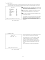
7 - 9 GAME ASSIGNMENTS
Selecting the GAME ASSIGNMENTS in the MENU mode causes the present game settings
to be displayed and also the game settings changes (game difficulty, etc.) can be made. Each
item displays the following content.
SETTING CHANGE PROCEDURE
1
2
3
Press the SERVICE BUTTON to move the “>” to the desired item.
Choose the desired setting change item by using the TEST BUTTON.
To return to the MENU mode, move the arrow to EXIT and press the TEST BUTTON.
GAME ASSIGNMENTS
START TIME
TIME DIFICULTY
GAME DIFFICULTY
50
4/8
4/8
START TIME
This is the time alloted at the time of game start. Setting is
possible starting from the shortest time sequentially in order of
35, 40, 45, 50, 55, -60, 65, and 70.
TIME DIFFICULTY
Refers to the amount of BONUS TIME to be added when the
taxi picks up the Customer. This can be set from 1/8 to 8/8 in 8
steps. The difficulty increases sequentially in order starting
from 1/8.
>EXIT
SELECT WITH SERVICE BUTTON
AND PRESS TEST BUTTON TO EXIT
GAME DIFFICULTY
Sets the difficulty level in 4 categories, i.e., EASY, NORMAL,
HARD, and HARDEST.
26
7 - 10 COIN ASSIGNMENTS
The “COIN ASSIGNMENTS” mode permits you to set the start number of credits, as well as the basic numbers
of coins and credits. This mode expresses “how many coins correspond to how many credits.”
SETTING CHANGE PROCEDURE
Setting changes cannot be stored unless the TEST BUTTON is pressed
while the arrow is on EXIT.
1
Press the SERVICE BUTTON to move the arrow to the desired item.
2
Choose the desired setting change item by using the TEST BUTTON.
3
To return to the MENU mode, move the arrow to EXIT and press the TEST BUTTON.
7 - 10 COIN ASSIGNMENTS
COIN ASSIGNMENTS
COIN/CREDIT SETTING
#1
CHUTE#1
1 COIN
1 CREDIT
CHUTE#2
1 COIN
1 CREDIT
ADDITIONAL SETTING
MANUAL SETTING
>EXIT
COIN/CREDIT SETTING
Sets the CREDITS increase increment per coin insertion.
There are 27 setings from #1 to #27, expressed in XX
CREDIT as against XX COINS inserted. (TABLE 7.10a,
7.10b) #27 refers to FREE PLAY.
When the COIN CHUTE TYPE is set to INDIVIDUAL,
there are some setting numbers not displayed as indicated in
TABLE 7.10b.
MANUAL SETTING
This allows credit increase setting as against coin insertion
to be further set in the manner finer than COIN/CREDIT
SETTING (refer to TABLE 7.10c).
SELECT WITH SERVICE BUTTON
AND PRESS TEST BUTTON
27
TABLE 7.10a COIN/CREDIT SETTING (COIN CHUTE COMMON TYPE)
SETTING
SETTING #1
SETTING #2
SETTING #3
SETTING #4
SETTING #5
SETTING #6
SETTING #7
SETTING #8
SETTING #9
SETTING #10
SETTING #11
SETTING #12
SETTING #13
SETTING #14
SETTING #15
SETTING #16
SETTING #17
SETTING #18
SETTING #19
SETTING #20
SETTING #21
SETTING #22
SETTING #23
SETTING #24
SETTING #25
SETTING #26
SETTING #27
FUNCTIONING OF CHUTE#1
1 COIN
1 CREDIT
1 COIN
2 CREDITS
1 COIN
3 CREDITS
1 COIN
4 CREDITS
1 COIN
5 CREDITS
1 COIN
2 CREDITS
1 COIN
5 CREDITS
1 COIN
3 CREDITS
1 COIN
4 CREDITS
1 COIN
5 CREDITS
1 COIN
6 CREDITS
2 COINS
1 CREDIT
1 COIN
1 CREDIT
1 COIN
2 CREDITS
1 COIN
1 CREDIT
2 COINS
3 CREDITS
1 COIN
3 CREDITS
3 COINS
1 CREDIT
4 COINS
1 CREDIT
1 COIN
1 CREDIT
2 COINS
2 CREDITS
3 COINS
3 CREDITS
4 COINS
5 CREDITS
1 COIN
5 CREDITS
5 COINS
1 CREDIT
1 COIN
2 CREDITS
2 COINS
1 CREDIT
4 COINS
2 CREDITS
5 COINS
3 CREDITS
1 COIN
3 CREDITS
1 COIN
1 CREDIT
2 COINS
2 CREDITS
3 COINS
3 CREDITS
4 COINS
4 CREDITS
5 COINS
6 CREDITS
1 COIN
1 CREDITS
FREE PLAY
28
MANUAL SETTING
Selecting MANUAL SETTING in the COIN ASSIGNMENTS mode displays the following screen.
MANUAL SETTING
COIN TO CREDIT
1 COIN
BONUS ADDER
NO BONUS ADDER
1
1 CREDIT
2
COIN CHUTE #1 MULTIPLIER
1 COIN COUNTS AS 1 COIN
COIN
1
2
3
CREDIT 1
2
3
4
4
5
5
6
6
7
7
8
8
9
9
COIN CHUTE #2 MULTIPLIER
1 COIN COUNTS AS 1 COIN
COIN
1
2
3
CREDIT 1
2
3
4
4
5
5
6
6
7
7
8
8
9
9
3
>EXIT
SELECT WITH SERVICE BUTTON
AND PRESS TEST BUTTON
FIG. 7.11b MANUAL SETTING
1 Determines Coin/Credit setting.
2 This sets how many coins should be inserted to obtain one Service Coin.
3 This sets how many tokens one coin represents.
Table 7.10c MANUAL SETTING
COIN TO CREDIT
1 COIN
2 COINS
3 COINS
4 COINS
5 COINS
6 COINS
7 COINS
8 COINS
9 COINS
BONUS ADDER
NO BONUS ADDER
2 COINS GIVE 1 EXTRA COIN
3 COINS GIVE 1 EXTRA COIN
4 COINS GIVE 1 EXTRA COIN
5 COINS GIVE 1 EXTRA COIN
6 COINS GIVE 1 EXTRA COIN
7 COINS GIVE 1 EXTRA COIN
8 COINS GIVE 1 EXTRA COIN
9 COINS GIVE 1 EXTRA COIN
COIN CHUTE MULTIPLIER
1 COIN COUNTS AS 1 COIN
1 COIN COUNTS AS 2 COINS
1 COIN COUNTS AS 3 COINS
1 COIN COUNTS AS 4 COINS
1 COIN COUNTS AS 5 COINS
1 COIN COUNTS AS 6 COINS
1 COIN COUNTS AS 7 COINS
1 COIN COUNTS AS 8 COINS
1 COIN COUNTS AS 9 COINS
29
1 CREDIT
1 CREDIT
1 CREDIT
1 CREDIT
1 CREDIT
1 CREDIT
1 CREDIT
1 CREDIT
1 CREDIT
7 - 11 BOOKKEEPING
Choosing BOOKKEEPING in the MENU mode displays the data of operating status up to the present are shown on 2
pages. Press the TEST BUTTON to proceed to PAGE 2/2.
BOOKKEEPING
COIN CHUTE#*:
Number of coins put in each Coin Chute.
PAGE1/3
COIN CHUTE #1
COIN CHUTE #2
TOTAL COINS
XXXXXXXXXXX
XXXXXXXXXXX
XXXXXXXXXXX
COIN CREDITS
SERVICE CREDITS
TOTAL CREDITS
XXXXXXXXXXX
XXXXXXXXXXX
XXXXXXXXXXX
NUMBER OF GAMES
XXXXXXXXXXX
TOTAL
TIME
PLAY
TIME
AVERAGE PLAY
LONGEST PLAY
SHORTEST PLAY
XDXXHXXMXXS
XDXXHXXMXXS
XXMXXS
XXMXXS
XXMXXS
TIME
TIME
TIME
TOTAL COINS:
Total number of activations of Coin Chutes.
COIN CREDITS:
Number of credits registered by inserting coins.
In Page 2/3, Histogram of Number of Play as against Play
Time is displayed. For setting the DIFFICULTY, refer to this
histogram.
Page 3/3 displays the character’s selected frequency at the
time of Game Start.
PRESS TEST BUTTON TO CONTINUE
FIG. 7.11a BOOKKEEPING (1/3)
BOOKKEEPING PAGE 2/3
TIME HISTOGRAM
COURSE
BEGINNER
~2M29S
0
2M30S~2M44S
0
2M45S~2M59S
0
3M00S~3M14S
0
3M15S~3M29S
0
3M30S~3M44S
0
3M45S~3M59S
0
4M00S~4M14S
0
4M15S~4M29S
0
4M30S~
0
ADVANCED
0
0
0
0
0
0
0
0
0
0
BOOKKEEPING 3/3
EXPERT
0
0
0
0
0
0
0
0
0
0
FAVORITE CHARACTER
AXEL
0
B.D.JOE
0
GENA
0
GUS
0
PRESS TEST BUTTON TO EXIT
SELECT WITH SERVICE BUTTON
PRESS TEST BUTTON TO EXIT
FIG. 7.11b BOOKKEEPING (2/3)
FIG. 7.11c BOOKKEEPING (3/3)
7 - 12 BACKUP DATA CLEAR
Clears the contents of BOOKKEEPING and high
score player ranking entry.
BACKUP DATA CLEAR
YES (CLEAR)
>NO (CANCEL)
When clearing, bring the arrow to “YES” and when
not clearing, to “NO”, by using the SERVICE
BUTTON, and push the TEST BUTTON.
When the data has been cleared, “COMPLETED”
will be displayed. Bring the arrow to “NO” and
press the TEST BUTTON to cause the MENU
mode to return on to the screen.
Note that the contents of the GAME SETTING,
COIN SETTING, and BOARD SETTING are not
affected by BACKUP DATA CLEAR operation.
SELECT WITH SERVICE BUTTON
PRESS TEST BUTTON TO EXIT
FIG. 7.12 BACKUP DATA CLEAR
30
8. HANDLE MECHA
In order to prevent an electric shock and short circuit, be sure to turn power off
before performing work by touching the interior parts of the product.
Be careful so as not to damage wirings. Damaged wiring can cause an electric shock
or short circuit accident.
In the test mode, if the steering wheel’s VR variations are not within the allowable range, the VR installation
position adjustments or VR replacement is needed. Also, be sure to apply grease to the VR gear portion once
every 3 months.
8 - 1 REMOVING THE CONTROL PANEL
1
Turn the power switch off.
2
Remove a total of 4 tamperproof screws from both sides of the control panel’s front.
3
Remove the two tamperproof screws fromthe underside of the control panel.
4
Wiring connectors are connected inside the control panel. Carefully draw the control panel in a mnner so as not to
damage wiring.
5
Disconnect the wiring connector.
31
8 - 2 REPLACING AND ADJUSTING THE HANDLE’S VR
Never touch places other than those specified. Touching places not specified can
cause electric shock and/or short circuit.
After the replacement or adjustment of the VR, be sure to set the variable value of
the VR in the test mode’s Volume Setting.
REPLACING THE VOLUME
1
Turn off the power.
2
Disconnect the connector.
3 Take out the 2 screws which secure the volume Bracket and remove the Volume Bracket.
4
Take out the 2 screws to remove the Volume Gear and replace the Volume.
5 After replacing the Volume, perform Volume setting in the Volume Setting Mode.
ADJUSTING THE VOLUME
1
In the Test Mode, have the Volume value indicating screen displayed.
2
Loosen the 2 screws which secure the Volume Bracket to disengage Gear Mesh.
3 With the Steering Wheel in the centering position, cause gears to be engaged in the manner so that the Volume
Shaft is in the status shown below.
4
Fasten screws which secure the Volume Bracket.
5
Perform Volume setting as per the Volume Setting Mode.
32
8 - 3 GREASING
Never touch places other than those specified. Touching places not specified can
cause electric shock and/or short circuit.
After the replacement or adjustment of the VR, be sure to set the variable value of
the VR in the test mode’s Volume Setting.
Apply greasing to the Volume gear mesh portion every 3 months.
For spray greasing, use Grease Mate (Part No. 090-0066).
33
9. SHIFT LEVER
In order to prevent electric shock and short circuit, be sure to turn off the power
before performing work on the interior parts of the product.
Be careful not to damage wiring. Damaged wiring can cause electric shock or short
circuit.
Do not touch places other than those specified. Touching places other than those
specified can cause an electric shock or short circuit accident.
If the Shift Lever operation is not satisfactory, remove the Shift Lever in the following procedure and replace the
microswitch.
9 - 1 REMOVING THE SHIFT LEVER
1 Turn Power off.
2
Take out the 4 SPECIAL BOLTS and pull the SHIFT LEVER UNIT upward by paying careful attention so as not
to damage the wiring.
3 Disconnect the 2 connectors to allow the unit to be removed.
4 When reinstalling, follow the procedure oppisite as when removing. At this time, ensure that“DOWN” display
appears on the upper part as shown.
34
9 - 2 SWITCH REPLACEMENT
Each microswitch is secured with 2 screws. Remove the 2 screws and replace the Microswitch.
After replacing the Switch, check to see if the switch is inputted as per Shift Lever operation in the Test Mode.
35
10. ACCEL & BRAKE(S)
In order to prevent an electric shock and short circuit, be sure to turn power off
before performing work by touching the interior parts of the product.
Be careful so as not to damage wirings. Damaged wiring can cause an electric
shock or short circuit accident.
Do not touch places other than those specified. Touching places not specified can
cause an electric shock or short circuit accident.
If Accel and Brake operation is not satisfactory, adjustment of Volume installation position or Volume replacement is
needed. Also, be sure to apply greasing to the gear mesh portion once every three months.
10 - 1 ADJUSTING AND REPLACING THE V.R.
Check Volume values in the Test Mode.
Since work is performed inside the energized cabinet, be very careful so as not to touch undesignated portions. Touching places not specified can cause an electric shock or short circuit.
1
Take out the 2 truss screws and remove the Front Cover
from the Accel. & Brake unit.
2
Loosen the screw which secures the Potentiobase, and
adjust the Volume Value by moving the Base.
3
Secure the Potentiobase.
4
Perform Volume setting in the Volume Setting Mode.
36
Check Volume values in the Test Mode.
Since work is performed inside the energized
cabinet, be very careful so as not to touch
undesignated portions. Touching places not
specified can cause an electric shock or short
circuit.
1
Take out the 2 truss screws and remove the Front Cover
from the Accel. & Brake unit.
2
Loosen the screw which secures the Potentiobase, and
adjust the Volume Value by moving the Base.
3
Secure the Potentiobase.
4
Perform Volume setting in the Volume Setting Mode.
10 - 2 GREASING
Be sure to use designated grease. Using undesignated grease can
cause parts damage.
Once every 3 months, apply greasing to the Spring and Gear Mesh portion. For spray greasing, use GREASE MATE
(PART No. 090-0066).
37
11 . COIN SELECTOR
HANDLING THE COIN JAM
If the coin is not rejected when the REJECT BUTTON is pressed, open the coin chute door
and open the selector gate. After removing the jammed coin, put a normal coin in and check
to see that the selector correctly functions.
CLEANING THE COIN SELECTOR
1
2
3
4
5
6
GATE
The coin selector should be cleaned
once every 3 months. When cleaning,
follow the procedure below:
Turn the power for the machine OFF.
Open the coin chute door.
Open the gate and dust off by using a
soft brush (made of wool, etc.).
Remove and cleen smears by using a
soft cloth dipped in water or diluted
chemical detergent and then squeezed
dry.
Remove the CRADLE.
When removing the retaining ring(Ering), be very careful so as not to bend
the shaft.
Remove stain from the shaft and pillow
portions by wiping off with a soft cloth,
etc.
After wiping as per #5 above, further
apply a dry cloth, etc. to cause the coin
selector to dry completely.
FIG. 11a
CRADLE
FIG.11b
Never apply machine oil, etc. to
the coin selector
After cleaning the Coin Selecting,
Insert a regular coin in the normal
working status and ensure that
the Selector correctly functions.
COIN INSERTION TEST
Once a month, when performing the COIN SW
TEST, simultaneously check the following:
Does the Coin Meter count satisfactorily?
Does the coin drop into the Cashbox correctly?
Is the coin rejected when inserted while keeping
the REJECT BUTTON is pressed down?
Insert a coin
while keeping
the Reject
Button pressed
down and check
if it is
rejected.
COIN METER
FIG. 11c
38
OPTIONAL DOLLAR BILL ACCEPTOR
THE COIN DOOR ASSEMBLY USED ON CRAZY TAXI COMES
EQUIPPED TO ACCEPT A DOLLAR BILL ACCEPTOR. ALL NEEDED
WIRING CONNECTIONS ARE CONVIENENTLY LOCATED INSIDE THE
GAME FOR THIS APPLICATION.
THE COIN DOOR CAN ACCCOMMODATE THE FOLLOWING
VALIDATORS:
HOLE POSITION#1
(FORWARD-MOST POSITION)
Mars 2000 series
HOLE POSITION#2
Mars 2000 series
DBV45 (JCM)
HOLE POSITION #3
CURRENTLY NOT USED
HOLE POSITION #4
DSI01*
*The back flange on the chute can be removed for hold position #4.
If the flange is not removed, it may interfere with the back of the
cabinent.
The frame and cashbox enclosure on this coindoor has been modified to accomodate a Mars 2000 series
upstacker. A 2000 series stacker can be added by simply removing the top two entry door and replacing it with a one
entry door with a cut-out for a stacker. This one entry door can be ordered through Coin Controls or one of Coin Controls
authorized distributors. The part number is 91-4000-01. The Mars stacker can be obtained through an autherized Mars
distibutor.
39
40
12. MONITOR
When performing such work as installing and removing the monitor, inserting and disconnecting the external connectors to and from monitor, be sure to disconnect the power connector
(plug) before starting work. Proceeding the work without following this instruction can cause
electric shock of malfunctioning.
Using the monitor by converting it without obtaining a prior permission is not allowed. SEGA
shall not be liable for any malfunctioning and accident caused by said conversion.
Primary side and secondary side
The monitor’s circuit which is divided into the Primary
side and secondary side, is electrically isolated. Do
not touch the primary side and the secondary side
simultaneously. Failing to observe the instruction can
cause electric shock, and this is very dangerous.
When making monitor adjustments, use a nonconductive driver and make adjustment without
touching any other part other than the Adjustment
V.R. and Knob. Also, be sure not to cause a shortcircuit to the Primary side and the Secondary side. If
short-circuited, it can cause electric shock or malfunctioning, which is very dangerous.
High tension Voltage
Some of the parts inside the monitor are subject to high-tension voltage in excess of 20,000
volts and very dangerous. Therefore, do not touch the monitor interior. Should soldering &
paper wastes, etc. be mixed in the monitor, turn the power off so as not to cause malfunctioning or fire hazard.
Connecting the CRT and PCB
For combining the CRT and PCB, use the specified part No. to maintain the status of adjustments made at the factory. The anode of the CRT itself will be accumulitavely charged as time
elapses, generating high tension voltage which is very dangerous. The monitor should be used
with the Chassis, CRT and PCB assembled. When repair, etc. is required at the time of malfunctioning, be sure to send it in an “as assembled” condition. If these are disassembled, what’s
charged to said high tension voltage can be discharged, causing a very hazardous situation.
Therefore, under no circumstances should it be disassembled.
Static Electricity
Touching the CRT surface sometimes causes you to slightly feel electricity. This is because the
CRT surfaces are subject to static and will not adversly affect the human body.
Installation and removal
Ensure that the Magnetizer Coil, FBT (Fly-Back Transformer), Anode Lead and Focus Lead are
not positioned close to the sheet metal work’s sharp edges, etc. and avoid damaging the
insulated portions so as not to cause an electric shock and malfunctioning. (For the name of
parts, refer to the above figures.)
41
For the purpose of static prevention,
special coating is applied to the CRT
face of this product. To protect the
coating, pay attention to the following
points. Damaging the coating film can
cause electric shock to the customers.
For the caution to be heeded when
clearing, refer to the Section of Periodic
inspection Table.
Do not apply or rub with a hard item (a
rod with pointed edge, pen, etc.) to or
on C.R.T. surfaces.
Avoid applying stickers, seals, etc. on
the C.R.T. face.
Do not remove aluminum foils from the
C.R.T. corners. Removing the aluminum
foils can cause static prevention effects
to be lowered.
Monitor adjustments have been made at the time of shipment. Therefore do not make further adjustment without a justifiable reason.
Adjusting the monitor which contains high tension parts is dangerous
work. Also, an erroneous adjustment can cause deviated synchronization and image fault, resulting in malfunctioning.
When making adjustment, utilize a resinous Alignment Rod. Servicing
with bare hands or using conductive tools can cause electric shock.
42
43
13. REPLACEMENT OF FLUORESCENT LAMP
When performing the work, be sure to turn power off. Working
with power on can cause an electric shock or short circuit accident.
The Fluorescent Lamp, when it gets hot, can cause burns. Be
very careful when replacing the Fluorescent Lamp.
To perform work safely and securely, be sure to prepare a step which is in a
secure and stable condition. Not using a step or using an unstable step can
cause violent falling down accidents.
13 -1 REPLACEMENT OF FLUORESCENT LAMP
1
2
3
Take out the 3 Tamperproof screws from
the rear of the billboard.
.
Be sure to disconnect all connectors
conected to the Marquee assembly before
removing the Billboard and/or performing
work.
Take out the two screws which secure the
lower billboard plate mask and remove
billboard
44
14. PERIODIC INSPECTION TABLE
The items listed below require periodic check and maintenance to retain the performance of
this machine and ensure safe operation.
Be sure to check once a year to see if Power Cords are damaged, the plug is
securley inserted, dust is accumulated between the Socket Outlet and the Power
Plug, etc. Using the product with dust as is accumulated can cause a fire or
electrical shock.
Periodically once a year, request the place of contact herin stated or the Distributer, etc. where the product was purchased from, as regards to the interior
cleaning. Using the product with dust as is accumulated in the interior without
cleaning can cause a fire or short circuit accident. Note that cleaning the interior
parts can be performed on a pay-basis.
CLEANING CABINET SURFACES
If the cabinet is badly stained, use a cloth which is dipped in the chemical detergent liquid diluted with water and then
squezzed dry. Do not use thinner, benzine, alcohol or chemical dustcloth as these can damage Cabinet surfaces.
SEAT (Greasing to Seat Rail Portion)
Move the Seat to the rearmost portion and apply spray greasing to the
portion shown at the right once every 3 months by using NOK KLUBER
L60 or GREASE MATE SEGA PART No. 090-0066. After greasing, move
seat a few times forward and backward so as to allow the grease to be
applied all over uniformly. Be sure to wipe grease which attaches to the
surfaces of the PROTECT RUBBER on the seat Rail, or any excess grease.
45
15. TROUBLESHOOTING
Should trouble occur, first check connector connections.
PROBLEMS
CAUSE
COUNTERMEASURES
With Main SW
ON, no activation
Power is not supplied.
Plug in correctly
Power supply/voltage is not correct.
Make sure that power supply/voltage is
correct.
Check fuse. Remove the cause of
overload and replace fuse
AC main fuse causes the
power to be cut off due to momentary
overload.
Operation is
unsatisfactory
Volume Setting Failure
Perform Volume setting
Adjust or replace V.R.
Poor mesh of V.R. gear.
Adjust Gear mesh..
Spring failure due to secular change
of Accelerator and Brake Mecha.
Replace the Spring.
Irregular sound
emitted from
inside Rear Cabinet
Greasing to gear mesh portion is not
satisfactory, or extraneous matter
mixed in.
Apply greasing or eliminate extraneous
matter.
The color of the
image on PROJ.
screen is incorrect.
Connector connections are defective.
Check the connection for the RGB and
SYNC connectors of the PROJ. TERM.
BD and VPM BUFFER BD.
The image on PROJ.
screen has color
deviation.
Affected by the magnetic field of
installation location.
Make CONVERGENCE adjustment.
(Refer to Section 12.)
No sound is emitted.
Sound Volume adjustment is not
appropriate.
Adjust sound volume. (see Section 7).
Sound BD and speaker are
malfunctioning.
Perform sound test to find and replace
defective parts.(Refer to Section 7).
NETWORK check
will not finish.
Communication cable’s connection
failure.
Perform V.R. setting, Adjustment.
Communication play
is not possible.
Communication cable’s connection
failure.
Communication Play setting is wrong.
Check for Communication cable
disconnection
Correctly set in test mode.
No sound from
Cockpit.
In correct Cabinet Type Setting.
Correct Cabinet Type Setting.
The Fluorescent
lamp does not
light up.
The Fluorescent tube is burnt out.
Replace the Fluorescent tube
(Refer to Section 11).
Shift operation is not
is not satisfactory in
Manual transmission.
Shift SW malfunctioning.
Replace SW
46
16. GAME BOARD
In order to prevent an electrical shock, be sure to turn power off before
performing work by touching the interior parts of the product.
Be careful so as not to damage wirings. Damaged wiring can cause an
electric shock or short circuit accident.
Do not expose the Game BD, etc. without a good reason. In this product,
setting changes are made during the test mode. The Game BD need not be
operated. Use the Game BD, etc. as is with the same setting made at the
time of shipment.
16 -1 REMOVING THE GAME BOARD
To replace the IC Board or to change dip switch settings, take out the IC board using the following procedure;
1 Turn main switch off.
2 Unlock the base, and remove the 2 truss screws from the side of the base.
3 Turn the knob to unlock. The seat can be inclined in the direction shown. When inclining the seat, be careful not to
damage seat parts. Carefully rest the backrest portion of the seat on the ground.
4 If neccessary, protect the seat from damage by using a cloth or blanket on the floor.
5 Take off the 3 screws to remove the case lid. The game board is inside the shield case.
6 Take off a total of 4 screws from both sides with the seat being in an inclined state and remove the base lid F.
Removing base lid F allows the Elec Base to be seen.
47
16 - 2 REPLACEMENT OF FUSE
In order to prevent an electric shock, be sure to turn power off before performing
work by touching the interior parts of the product.
Be careful so as not to damage wirings. Damaged wiring can cause an electric shock
or short circiut accident
After eliminating the cause of the blowing of fuse, replace the fuse.
Depending on the cause of the fuse blowing, using the fuse as is blown can cause
generation of heat resulting in fire.
Incline the Seat and remove the Base Lid to view the Base interior. The composition of the Base interior is as shown
below. There is a fuse on each of the Connect BD. and Motor Drive BD. When replacing the fuse, be sure to use the
specified one.
48
16 - 3 COMPOSITION OF GAME BOARD
Ensure that the DIP SW setting is performed as designated as designated. Failure
to observe thisw may cause functioning not suitable for tyhe operation, or malfunctioning.
ASSY CASE NAO USA (840-0002D-01) :USA
DIP SW SETTING
IN the product, set all of the DIP SWes to OFF.
49
17. DESIGN RELATED PARTS
ITEM NO.
PART NO.
DESCRIPTION
1
2
6
7
8
9
10
11
12
13
14
16
17
18
19
20
DYN-0011
LOCAL PURCHASE
999-0771
999-0770
SPG-1201-E
DYN-1214-C
DYN-1214-D
DYN-1214-E
SPG-2002
999-0773
999-0772
999-0769
999-0768
999-0767
999-0766
999-0761
DENOMI PLATE W/O ORIGINAL
DENOMINATION SHEET 1 GAME
STICKER INSTRUCTION SH CTA
STICKER SUB INSTR SH CTA
METER PANEL
DESIGN PL TACO MTR TWIN
DESIGN PL OIL MTR TWIN
DESIGN PL WATER MTR TWIN
STEERING EMBLEM
STICKER MONITOR COVER L CTA
STICKER MONITOR COVER R CTA
STICKER MAIN BASE L CTA
STICKER MAIN BASE R CTA
STICKER MAIN BASE C CTA
STICKER SEAT REAR CTA
MARQUEE PLEX CRAZY TAXI
50
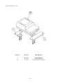
18. PARTS LIST
TOP ASSY CRAZY TAXI
ITEM NO.
PART NO.
DESCRIPTION
1
2
3
4
22
23
25
29
201
202
203
204
205
206
209
999-0774
DUT5-0300
999-0774
200-5787
INY-0004
DYN-0008
DYN-0011
LOCAL PURCHASE
LOCAL PURCHASE
068-852216
000-T00440-0B
LOCAL PURCHASE
LOCAL PURCHASE
000-T00416-0C
010-P00408-F
ASSY BILLBOARD CTA
ASSY COIN CHUTE TOWER
ASSY COCKPIT 1P CTA
CLR DSPLY 29 TYPE 31K 100V
BACK LID INY
BACK LID B
DENOMI PLATE W/O ORIGINAL
MARQUEE RETAINING PLATE
1/4-20X1 1/4” TMPR PRF SCREW
FLT WSHR M8
M SCR PH W/FS BLK M4X40
HEX BLT 8/32-20X1
SPR WSHR 8/32-20X1
M SCR TH CRM M4X16
S-TITE SCR PH W/F M4X8
51
ASSY BILLBOARD STD (999-0774)
ITEM NO.
PART NO.
DESCRIPTION
1
2
3
4
101
102
103
999-0761
999-0733
999-0731
999-0732
LOCAL PURCHASE
DRT1-0230
DRT1-0240
MARQUEE PLEX CRAZY TAXI
LOWER MARQUEE GRILL
MARQUEE COVER L
MARQUEE COVER R
ASSY FL 20W EX W/CONN HIGH S
LAMP UNIT
SKT UNIT
52
ASSY LAMP UNIT (DRT1-0230)
ITEM NO.
PART NO.
DESCRIPTION
1
101
201
202
DRT5-0231
999-0734
000-T00408-0C
068-441616-0C
LAMP HOLDER
ASSY YELLOW LAMP COVER
M SCR TH CRM M4X8
FLT WSHR CRM 4.4-16X1.6
ASSY SKT UNIT (DRT1-0240)
ITEM NO.
PART NO.
DESCRIPTION
1
101
201
DRT5-0241
LOCAL PURCHASE
000-P00320-S
SKT HOLDER
BULB SKT
M SCR PH W/S M3X20
53
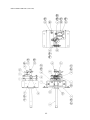
ASSY COINCHUTE TOWER (DUT5-0300)
54
ASSY COINCHUTE TOWER (DUT5-0300)
ITEM NO.
PART NO.
DESCRIPTION
1
2
3
4
5
10
11
12
13
101
102
103
104
105
106
SPG1-0350
SPG1-0301
DYN-0302Y
DP-1167
BOX-CASH
DYN-0305
105-5202
SPG-0302
SPG-0303
92-1003-05*
220-5412
999-0169
220-5574
220-5575
999-0167
SW UNIT
COIN CHUTE TOWER
COIN METER BRKT
TNG LKG
CASH BOX
TOWER BRKT
HOLE COVER
WIRE BOX
WIRE BOX LID
ASSY C.C. 2DR
MAG CNTR W/CONN
CASTER 2 1/2”
CAM LOCK W/KEYS
CAM LOCK MASTER W/O KEY
LEG LEVELER
* This coin door is produced by Coin Controls and can be ordered through your local distributor.
55
SW UNIT (SPG5-0350)
ITEM NO.
PART NO.
DESCRIPTION
1
101
102
103
104
105
SPG5-0351
509-5028
220-5179
601-0042
220-5412
509-5453-91-V-B
SWITCH BRKT
SW PB 1M
VOL CONT B-5K OHM
KNOB 22MM
MAG CNTR W/CONN
ROCKER SWJ8 V-B
56
AC UNIT (DRT1-0400)
TEM NO.
PART NO.
DESCRIPTION
1
101
102
105
SPG5-0401
600-5843-25
280-5134-6N34
509-5453-91-V-B
AC BRKT
CA & PLUG ASSY 15A W/F-L=2.5M
BUSHING STRAIN RELIEF 6N34
SW ROCKER J8 V-B
57
ASSY MONITOR COVER R 1P (DRT5-1045)
ITEM NO.
PART NO.
DESCRIPTION
1
DRT5-1046
COVER PANEL R 1P
58
ASSY MONITOR COVER L 1P (DRT5-1030)
ITEM NO.
PART NO.
DESCRIPTION
1
DRT5-1031
COVER PANEL L 1P
59
ASSY SPEAKER (SPG-1100)
ITEM NO.
PART NO.
DESCRIPTION
1
101
INY-1701
130-5159
SPEAKER BRKT
GULL BOX SPEAKER 8OHM 5W
60
ASSY VIRTUAL BUTTON TWIN (DRT5-1290)
ITEM NO.
PART NO.
DESCRIPTION
1
2
101
102
DRT5-1291
171-6478B
212-5205-12
509-5560-Y
VR BUTTON BRKT
PC BD LIGHTING SW
CONN JST M 12P RTA
PB SW W/L 6V 1L Y
61
ASSY BASE BOX (DRT1-1500)
ITEM NO.
PART NO.
DESCRIPTION
1
2
3
4
5
6
7
8
101
DRT1-1501
DYN-2003
DYN-2004
DYN-2005X
DYN-2006
DRT-1510
DYN-2007X
DYN-2009X
220-5575
MAIN BASE
BASE LID F
LOCK TNG
FLOOR MAT
HINGE 480
ASSY BASE LID R
LID EDGE L
LID EDGE R
CAM LOCK MASTER W/O KEY
62
MAIN BASE (DRT1-1501)
ITEM NO.
PART NO.
DESCRIPTION
1
2
3
4
5
DYN-2002X-A
999-0769
999-0768
999-0167
999-0169
MAIN BASE BLANK
STICKER BASE L
STICKER BASE R
LEG ADJUSTER BOLT 1/2X13X3
CASTER 2 1/2"
63
ASSY SEAT TWIN 1P (DRT-1600)
64
ASSY SEAT TWIN 1P (DRT-1600)
ITEM NO.
PART NO.
DESCRIPTION
1
2
3
4
5
6
7
8
9
10
11
12
13
14
15
101
102
103
105
106
107
201
203
205
206
210
211
STC-1650
DRT-1602-A
DRT-1603-A
STC-2201
STC-1604
DRT-1604
STC-1606
STC-1607
STC-1608
STC-1609
STC-1610
STC-1611
STC-1612
STC-1613
INY-1302-B
601-9059
601-9060
130-5159
601-6563-188
601-6563-100
280-5297
000-P00410-W
030-000816-S
050-H00800
060-S00800
000-T00616-0B
010-P00408-F
ASSY WOOFER
UPPER SEAT
LOWER SEAT
SEAT BASE
SEAT FRAME
SEAT REAR COVER 1P
SEAT MOUNT TRAY
SP MOUNT BRKT
SPEAKER NET L
SPEAKER NET R
SAFETY GUARD
CABLE BEAR BRKT
PROTECT RUBBER
SAFETY GUARD F
MASK CUSHION SIDE
SEAT RAIL L
SEAT RAIL R
GULL BOX SPEAKER 8OHM 5W
BUSH 2.4T
BUSH 2.4T
SCRIVET 8 1K31
M SCR PH W/FS M4X10
HEX BLT W/S M8X16
HEX NUT M8
SPR WSHR M8
M SCR TH BLK M6X16
S-TITE SCR PH W/F M4x8
65
ASSY WOOFER (STC-1650)
ITEM NO.
PART NO.
DESCRIPTION
1
2
101
STC-1651
STC-1652
130-5160
WOOFER BRKT F
WOOFER BRKT R
SUB WOOFER 4 OHM 30W
66
ASSY ACCEL&BRAKE (SPG-2200)
67
ASSY ACCEL&BRAKE (SPG-2200)
ITEM NO.
PART NO.
DESCRIPTION
1
2
3
4
5
6
7
8
9
10
11
12
13
14
15
16
17
19
20
21
101
102
104
105
106
201
202
203
204
205
206
207
208
209
210
SPG-2201
SPG-2202
SPG-2203
SPG-2204
SPG-2205
SPG-2206
SPG-2207
SPG-2208
SPG-2209
SPG-2210
SPG-2211
SPG-2212
SPG-2213
SPG-2214
SPG-2215
SPG-2216
SPG-2217
SPG-2219
SPG-2220
SPG-2221
100-5263
220-5484
601-7944
310-5029-F15
280-0419
028-A00304-P
020-000520-0Z
000-P00420
000-P00508-W
000-T00408-0C
FAS-450005
000-P00405
FAS-000001
050-H00500
060-F00400
BASE
ACCEL PEDAL
BRAKE PEDAL
ACCEL SPRING
BRAKE SPRING
SHAFT
ACCEL GEAR
BRAKE GEAR
NUETRAL STOPPER
VR PLATE ACCEL
VR PLATE BRAKE
AMPL GEAR
GEAR SHAFT
STOPPER
RUBBER CUSHION
COVER
VR COVER
GEAR STAY
WSHR
NUETRAL STOPPER
BEARING 12
VOL CONT B-5K OHM
GEAR 15
SUMI TUBE F F 15MM
HARNESS LUG
SET SCR HEX SKT CUP P M3X4
HEX SKT H CAP SCR BLK M5X20
M SCR PH M4X20
M SCR PH W/FS M5X8
M SCR TH CRM M4X20
SPR PIN BLK OZ 6X10
M SCR PH M4X5
M SCR TH CRM M3X6
HEX NUT M5
FLT WSHR M4
68
ASSY HANDLE MECHA (CTA-2100)
69
ASSY HANDLE MECHA (CTA-2100)
ITEM NO.
PART NO.
DESCRIPTION
1
2
3
4
5
6
7
8
9
10
11
12
13
14
15
16
17
18
19
20
21
22
CTA-2101
CTA-2101
CTA-2103
CTA-2104
CTA-2105
CTA-2106
CTA-2107
DYN-1262
DYN-1269
DYN-1273
BVG-1340
BVG-1341
SLC-1130
SLC-1141X
SOR-2112
SOR-2113
SOR-2115
SPG-2109
601-6172
601-6959
601-8966
SLC-1108
HANDLE BASE
BASE LID
HANDLE SHAFT
STOPPER BOLT
SPRING HOOK
SPACER RING
VR BRKT
SWING ARM SHAFT
EXT SPRING
SWING ARM
FLT WSHR 8.1-12X2
FLT WSHR 4.1-12X2
ADJUST RING
WHITE CAM
BEARING SHAFT
SPACER
KEY 5X10
STOPPER RUBBER
GEAR 48
GEAR 64
GEAR HOLDER
WIRE HOLDER
101
102
103
104
100-5018
100-5112
100-5041
220-5484
BEARING BALL 8
BEARING 17
BEARING NSK F688 ZZ
VOL CONT B-5K OHM
201
202
203
204
205
206
207
208
209
210
211
028-A00408-P
028-A00308-P
FAS-650011
000-P00408-W
000-P00412-W
060-F00600
050-U00600
060-F00800
050-U00800
065-E00700
060-S00800
SET SCR HEX SKT CUP P M4X8
SET SCR HEX SKT CUP P M3X8
STP RING BLK OZ S17
M SCR PH W/FS M4X8
M SCR PH W/FS M4X12
FLT WSHR M6
U NUT M6
FLT WSHR M8
U NUT M8
E RING 7MM
SPR WSHR M8
70
ASSY SHIELD CASE NAO (840-0002D-01)
ITEM NO.
PART NO.
DESCRIPTION
1
2
840-0001A-01
840-0001C
SHIELD CASE CTA NAO USA
ROM CASE NAO
71
ASSY ELEC BASE (CTA1-4500)
ITEM NO.
PART NO.
DESCRIPTION
1
NOT AVAILABLE
WOODEN BASE ELEC
101
102
103
104
105
106
107
108
560-5360-01
LOCAL PURCHASE
838-13759
838-11651-91
837-13551-91
840-0002D-01
400-5397
838-13616
XFMR 12.8V 6.3A 34V 4.2A
FUSE BLOCK W/ FUSES
RECTIFIER BD
LOW PASS AMP
I/O BD
NAOMI BD
PWR SPPLY
AUDIO POWER AMP 2CH
72
ASSY COCKPIT 1P (DRT1-10001)
73
ASSY COCKPIT 1P (DRT1-10001)
ITEM NO.
PART NO.
DESCRIPTION
1
2
3
4
5
6
7
8
9
10
11
12
101
105
106
107
108
109
DRT5-20001
DRT5-1030
DRT5-1045
DRT5-1201
SPG-1004
SRT-1002
INY-1016
SPG-1008
TTR-1067X
SPG-1005
DYN-1025
INY-1015
200-5787
280-5112
280-5113
280-5114
280-5185-6
601-6231-C100
ASSY MAIN BASE 1P
ASSY MONITOR COVER L 1P
ASSY MONITOR COVER R 1P
ASSY CONTROL PANEL CTA
MONITOR STAND
WIRE COVER BOX
MONITOR SUPPORT
ROOF LID
MONITOR MASK
MASK HOLDER
RUBBER CUSHION
CRT ADJUST PANEL
ASSY CLR DSPL 29 TYPE 31K 100V
BUSH FOR TV
COLLAR FOR TV
SPACER 6.4-25x2
SPACER TUBE L=6
EDGING NEW TYPE
74
ASSY CONTROL PANEL (DRT1-1200-02)
75
ASSY CONTROL PANEL (DRT1-1200-02)
ITEM NO.
PART NO.
DESCRIPTION
1
2
3
4
5
6
7
9
10
11
12
13
DYN-1201
DYN-1209X
SPG-2002
DRT1 -1201-01
SPG-1205
INY-1204
DYN-1223X
SPG-1204
CTA-2100
610-0384
DRT5-1290
SPG-2039
STEERING WHEEL
HANDLE COLLAR
STEERING EMBLEM
CONTROL PANEL COVER ENG
CONTROL PANEL BRKT
SHIFT COVER INY
SHIFT COVER B
SPL BLT M8
ASSY HANDLE MECHA
ASSY SHIFTER
ASSY VIRTUAL BUTTON CTA
SPACER RING
201
202
203
204
205
206
207
208
210
212
020-000820-0Z
060-F00800
060-S00800
050-H00800
FAS-200013
000-T00416-0B
000-P00412-W
008-T00516-0B
030-000820-S
000-T00412-0C
HEX SKT H CAP SCR BLK OZ M8X20
FLT WSHR M8
SPR WSHR M8
HEX NUT M8
HEX SKT H CAP SCR CRM M4X16
M SCR TH BLK M4X16
M SCR PH W/FS M4X12
TMP PRF SCR TH BLK M5X16
HEX BLT W/S M3X12
M SCR TH CRM M4X12
76
ASSY MAIN BASE 1P (DRT5-20001)
77
ASSY MAIN BASE 1P (DRT5-20001)
ITEM NO.
PART NO.
DESCRIPTION
1
2
3
5
6
7
8
9
10
101
DRT-1500
DRT-1600
SPG-2200
CTA1-4500
SRT1-0400
SPG-1502
RAL-2007
RAL-2008
SPG-1503
260-0011
ASSY BASE BOX
ASSY SEAT TWIN 1P
ASSY ACCEL&BRAKE
ASSY ELEC BASE
AC UNIT
PEDAL BASE
RUBBER HOLDER R TWIN
RUBBER HOLDER L TWIN
FAN BRKT
AXIAL FLOW FAN AC100V 50-60 HZ
78