1
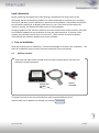
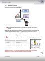
c.LOGiC lite-Interface
C1-MFD2
For navigation systems
Volkswagen MFD2/RNS2
Skoda Nexus
Only for vehicles WITHOUT factory rear-view camera
Product features
• full plug and play multimedia interface
• 1 AV-input with separate IR-control channel
• control of after-market devices, e.g. DVB-T tuner, DVD-player, DVD-changer, …
• after-market rear-view camera input
• automatic switching to rear-view camera input
• rear-view camera power (+12V max 1A)
• power on remote out trigger signal (+12V max. 1A) to switch on connected devices
Version 08.01.2013
C1-MFD2
Contents
1. Prior to Installation
1.1.
1.2.
Delivery contents
Check compatibility of vehicle and accessories
2. Connection schema
3. Installation
3.1.
3.2.
3.3.
3.3.1.
3.3.2.
3.3.3.
Interconnecting Interface-box and harness
Connections to head-unit
Connecting peripheral devices
AV-source
Installing AV-source’s IR-sensor additionally
After-market rear-view camera
4. Operation
4.1.
4.2.
4.3.
4.4.
Selecting the c.LOGiC as current AV-source
Assigning device controls
Button assignment table
Picture settings
5. Specifications
6. Technical support
Page
1
Appendix A – Device control table
Version 08.01.2013
C1-MFD2
Legal Information
By law, watching moving pictures while driving is prohibited, the driver must not be
distracted. We do not accept any liability for material damage or personal injury resulting,
directly or indirectly, from installation or operation of this product. This product should only
be used while standing or to display fixed menus or rear-view-camera video when the
vehicle is moving, for example the MP3 menu for DVD upgrades.
Changes/updates of the vehicle’s software can cause malfunctions of the interface. We offer
free software-updates for our interfaces for one year after purchase. To receive a free
update, the interface must be sent in at own cost. Labor cost for and other expenses
involved with the software-updates will not be refunded.
1. Prior to installation
Read the manual prior to installation. Technical knowledge is necessary for installation. The
place of installation must be free of moisture and away from heat sources.
1.1.
Delivery contents
Take down the SW-version and HW-version of the interface boxes, and store this
manual for support purposes.
Interface-box
C1C-M01
HW_____ SW_____
Harness
C1C-VW02
If remote function for the connected devices shall be used, additional an IR-
Page
2
remote cable and Y-adapter are needed, see chapter AV-source .
Version 08.01.2013
C1-MFD2
1.2.
Check compatibility of vehicle and accessories
Requirements
Vehicle
Volkswagen and Skoda
Navigation
MFD2/RNS2 or Nexus navigation
Limitations
Factory-TV-tuner
Must NOT be installed.
Page
3
2. Connection schema
Version 08.01.2013
C1-MFD2
3. Installation
Switch off ignition and disconnect the vehicle’s battery! If according to factory rules
disconnecting the battery has to be avoided, it is usually sufficient to put the vehicle is
sleep-mode. In case the sleep-mode does not show success, disconnect the battery with a
resistor lead.
Place of installation is behind the head-unit.
3.1.
Interconnecting Interface-box and harness
Page
4
Plug harness C1C-VW02 into 12pin Molex of Interface-Box C1C-M01.
Version 08.01.2013
C1-MFD2
3.2.
Connections to head-unit
Remove the head-unit from the dash-board.
Plug female 18pin AMP-connector of C1C-VW02 into male 18pin AMP-socket of
head-unit.
Note: If the 18pin AMP-socket of the head-unit is already occupied, the vehicle probably has
a factory rear-view camera or a factory TV-tuner. In case of a factory tuner, it must be
uninstalled: disconnect the female 18pin AMP-connector of the factory harness and
disconnect all wires from the factory TV-tuner. In case of a factory rear-view camera you
have ordered/received the wrong product, call for support.
Connect the loose red cable to +12V battery, the loose black cable to ground, the
loose yellow cable to CAN-HIGH and the loose blue cable to CAN-LOW of the vehicle.
Cable colour
●● Red/Yellow
● Brown
●● Orange/Green
●● Orange/Brau
Assignment
+12V Permanent Pin 15
Ground Pin 12
CAN HIGH Pin 9
CAN LOW Pin 10
Quadlock male of vehicle
Page
5
No liability for vehicle wire colors and pin definition! Possible changes by the vehicle
manufacturer. The given information must be verified by the installer.
Version 08.01.2013
C1-MFD2
3.3.
Connecting peripheral devices
It is possible to connect one after-market AV-source and an after-market rear-view camera
to the c.LOGiC Interface.
Before final installation of the peripheral devices, we recommend to test-run the c.LOGiC
functions to detect incompatibility of vehicle, navigation, factory accessories or peripheral
devices as soon as possible.
3.3.1. AV-source
The c.LOGiC interface has the possibility to connect and remotely control by navigation
buttons one pre-programmed device. The device list in the device control table (Appendix A)
shows the pre-programmed remote channels and the related IR-remote cables STA-xxx
which must be ordered separately for the control of the device.
Using the respective STA-xxx IR-control cable, interconnect the blue female 3pin AMP
connector of harness C1C-VW02 and the IR-port of the AV-source.
Version 08.01.2013
C1-MFD2
Page
The pink ACC-output wire (+12V max 1A) of the 4pin cable can be connected to the
ACC-input wires of the connected device to switch it on. It carries +12V when the
head-unit is running.
6
Using an RCA-cable, interconnect the female RCA-port Video In of the Interface-box
C1C-M01 with the AV-output of the AV-source.
3.3.2. Installing AV-source’s IR-sensor additionally
Additionally to the control via OEM navigation, it is possible to install the original IR-sensor
of a connected device. By using the respective Y-adapter (e.g. STA-Y35MM or STA-RJ12) for
the IR-Port of the connected device, the controls of navigation AND device’s IR-sensor can be
connected and used simultaneously. Installation of the IR-sensor is recommended as the
controls via navigation are limited, and not all functions may be covered.
3.3.3. After-market rear-view camera
Connect the video RCA of the after-market rear-view camera to female
RCA connector R-CAM IN of Interface-box C1C-M01.
Connect the green wire of the 4pin cable to the camera power supply (+12V max. 1A)
of the after-market rear-view camera and the grey wire to ground of the vehicle. The
green wire is high (+12V max. 1A) when reverse gear is engaged. The white wire is
not connected and has to be isolated. In some cases it is possible that the automatic
switching does not work. In this case connect the white wire to the reverse gear light
(+12V).
4. Operation
4.1.
Selecting the c.LOGiC as current AV-source
Page
7
CD-Version - Push AUX button of head-unit , then select
TV to choose the c.LOGiC as current AV-source.
DVD-Version - Push CD button of head-unit, then select
AUX to choose the c.LOGiC as current AV-source.
Version 08.01.2013
C1-MFD2
4.2.
Assigning device controls
After selecting the c.LOGiC as current AV source, longpress number “1” key.
The MFD will display “TV 1” and “RC01”. Turn right knob until the devicerelated IR-code for the AV-source as described in device control table
(appendix A) is reached. Push right knob to confirm the assignment.
If the vehicle has no MFD display in the instrument panel (for example in
case of retrofitted navigation systems), you must count the notches when
turning the knob (to the right +1, to the left -1). At the same time, remember
that the starting point is channel RC01 (the first notch to the right is then
already RC02).
4.3.
Button assignment table
Page
8
The button assignment table shows which functions of the connected device can be
executed by head-unit buttons. Once the AV-input is activated, the head-unit button in the
left column will execute the function described in the corresponding device column. The
function description equals the remote control buttons of the optional c.LOGiC remote
control or the additional device. On the additional device the writing may vary (e.g. AV
instead of Source).
Version 08.01.2013
C1-MFD2
Button assignment table c.LOGiC MFD2/RNS2/Nexus
Headunit
button
1
DVB-T
USB-LiNK
DVD-player
DVDchanger
OK
POWER
PLAY
PLAY
PLAY/PAUSE
SCAN
2
AV
MEDIA
AV
AV
EJECT
MODE
3
EPG
VOL+
PBC
PBC
SHUFFLE
FM
REPEAT
DISPLAY
4
INFO
VOL-
TITLE
TITLE
5
SCAN
ZOOM
ZOOM
DISC
iPod®-control
Analog-tuner
SCAN
6
MENU
SETUP
SETUP
SETUP
LIGHT
ADJUST
6 long
POWER
POWER
POWER
POWER
POWER
POWER
7
DISPLAY
MEDIA
DISPLAY
DISPLAY
8
AUDIO
AUDIO
AUDIO
AUDIO
9
→
→
→
→
→
CH +
10
←
←
←
←
←
CH -
12
↓
↓
↓
↓
↓
VOL -
13
↑
↑
↑
↑
↑
VOL +
14
OK
OK / PLAY
OK
OK
ENTER
MODE
11
EXIT
EXIT
STOP
STOP
PLAY
MUTE
15
CH -
TRACK -
TRACK -
TRACK -
TRACK -
CH -
16
CH +
TRACK +
TRACK +
TRACK +
TRACK +
CH +
DISPLAY
AUDIO
Additionally to the head-unit buttons, the steering-wheel buttons UP and DOWN can be
used for remote functions. DOWN-button has the same function as 15 on the head-unit and
UP-button has the same function as 16 on the head-unit.
4.4.
Picture settings
By pressing the button 17, it is possible to switch between 4:3 and 16:9 picture format.
To enter the picture settings menu longpress button 11.
The picture settings menu always
starts with the brightness settings.
The respective current picture value is
displayed on the instrument panel.
Press the right knob to change from
brightness to colour and contrast
(after contrast, the interface starts again
with brightness).
Page
9
Turn the right knob to change the
current picture value. To quit the
settings menu press “ESC”-button.
Version 08.01.2013
C1-MFD2
5. Specifications
Operation voltage
Stand-by power drain
Operation power drain
Power consumption
Temperature range
Weight
Measurements (box only) B x H x T
10.5 – 14.8V DC
<1mA
240mA
3W
-30°C to +80°C
95g
106 x 30 x 71 mm
6. Technical Support
Caraudio-Systems Vertriebs GmbH
manufacturer/distribution
Rheinhorststr. 22
D-67071 Ludwigshafen am Rhein
NavLinkz GmbH
corporate sales/tech dealer-support
Eurotec-Ring 45
D-47445 Moers
phone +49 180 3 907050
email [email protected]
Page
10
Legal disclaimer: Mentioned company and trademarks, as well as product names/codes are registered
trademarks ® of their corresponding legal owners.
Version 08.01.2013
C1-MFD2