1
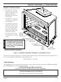
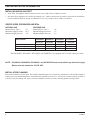
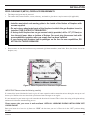
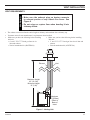
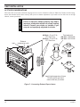
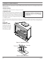
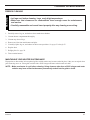
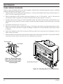
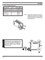
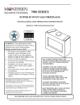
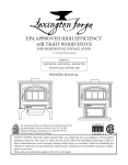
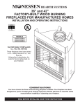
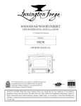
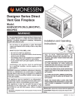
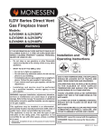
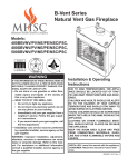
DIRECT VENT GAS INSERT
INSTALLATION AND
OPERATING
INSTRUCTIONS
MODELS:
IDV490NVC, IDV490PVC,
IDV380NVC, AND IDV380PVC
WARNINGS
IF THE INFORMATION IN THESE INSTRUCTIONS
ARE NOT FOLLOWED EXACTLY, A FIRE OR
EXPLOSION MAY RESULT CAUSING PROPERTY
DAMAGE, PERSONAL INJURY OR LOSS OF LIFE.
–
Do not store or use gasoline or other flammable vapors and liquids in the vicinity of this or
any other appliance.
–
WHAT TO DO IF YOU SMELL GAS
• Do not try to light any appliance.
• Do not touch any electrical switch; do not use any phone in your building.
• Immediately call your gas supplier from a neighbor's phone. Follow the gas supplier's
instructions.
• If you cannot reach your gas supplier, call the fire department.
–
Installation and service must be performed by a qualified installer, service agency or the
gas supplier.
This appliance is only for use with the type of gas indicated on the rating plate. This appliance is
not convertible for use with other gases, unless a certified kit is used.
READ BEFORE INSTALLING. SAVE THESE INSTRUCTIONS
CONTENTS
Thank you and congratulations on your purchase of a Monessen Fireplace.
Important Safety Information .......................... 3
Log Placement ................................................ 21
Product Features .............................................. 5
Surround and Trim Installation ..................... 24
Installing Facing .......................................... 24
Installing On/Off Switch ............................... 24
Code Approval .................................................. 5
Pre-Installation Information
Installing Above 2000 Feet ............................ 6
Orifice Sizes, Pressures and BTUs ............... 6
Insert Dimensions ......................................... 6
Fireplace and Insert Dimensions .................... 7
General Installation Information ..................... 8
Clearances .................................................... 8
Installation......................................................... 9
Insert Clearances .......................................... 9
Mantel Clearances ........................................ 9
Hearth Requirements .................................... 9
Insert Placement ......................................... 10
Zero-Clearance (Metal) Fireplace
Requirements ...............................................11
Vent Installation .............................................. 12
Installation Precautions ............................... 12
Vent Requirements ..................................... 13
Altitude Considerations ............................... 14
Vent Configurations ..................................... 15
Manifold Removal and Installation .............. 16
Filigree Panels and Cabinet
Door Frame Installation ............................ 25
Door Installation ............................................. 26
Operating Instructions ................................... 27
What To Do If You Smell Gas ...................... 27
Lighting Pilot for the First Time ................... 27
Lighting Pilot ............................................... 28
Lighting Burner ............................................ 29
To Turn Off Gas ........................................... 29
Adjusting Blower Speed .............................. 29
Air Shutter Adjustment (Natural Gas Only) .. 30
Glass Replacement ........................................ 31
Cleaning Maintenance.................................... 32
Venting System ........................................... 32
Cleaning Glass ............................................ 32
Pilot and Burner Flames ............................. 32
Firebox Cleaning ......................................... 33
Maintaining Your Heater’s Appearance ....... 33
Yearly Service Procedure ............................ 34
Blower.............................................................. 35
Insert Installation
Check Gas Type.......................................... 17
Installing Gas Piping to Insert/Burner System
Location ...................................................... 17
Troubleshooting ............................................. 38
Checking Gas Pressure ................................. 19
Warranty ...........................................Back Cover
Replacement Parts ......................................... 36
Electrical Installation ..................................... 20
Electrical Wiring .......................................... 20
Remote Wall Switch .................................... 20
2
57D0016
IMPORTANT SAFETY INFORMATION
WARNINGS
INSTALLER
Please leave these instructions with the appliance.
OWNER
Please retain these instructions for future reference.
• Read this owner’s manual carefully and completely before trying to assemble, operate,
or service this insert.
• Any change to this insert or its controls can be dangerous.
• Improper installation or use of this insert can cause serious injury or death from fire,
burns, explosions, electrical shock and carbon monoxide poisoning.
• Improper installation, adjustment, alteration, services or maintenance can cause injury
or property damage. Refer to this manual. For assistance or additional information
consult a qualified installer, service agency or the gas supplier.
• DUE TO HIGH TEMPERATURES, THE APPLIANCE SHOULD BE LOCATED OUT OF
TRAFFIC AND AWAY FROM FURNITURE AND DRAPERIES.
• CHILDREN AND ADULTS SHOULD BE ALERTED TO THE HAZARDS OF HIGH
SURFACE TEMPERATURE AND SHOULD STAY AWAY TO AVOID BURNS OR CLOTHING
IGNITION.
• YOUNG CHILDREN SHOULD BE SUPERVISED WHEN THEY ARE IN THE SAME ROOM
AS THE APPLIANCE.
• CLOTHING OR OTHER FLAMMABLE MATERIAL SHOULD NOT BE PLACED ON OR
NEAR THE APPLIANCE.
• KEEP THE ROOM AREA CLEAR AND FREE FROM COMBUSTIBLE MATERIALS,
GASOLINE, AND OTHER FLAMMABLE VAPORS AND LIQUIDS.
This insert is a vented product. This insert must be properly
installed by a qualified service person. The glass door must be
properly seated and sealed. If this unit is not properly installed
by a qualified service person with glass door properly seated
and sealed, combustion leakage can occur.
CARBON MONOXIDE POISONING: Early signs of
carbon monoxide poisoning are similar to the flu with headaches, dizziness and/or nausea. If you have these signs, the
insert may not have been installed properly. Get fresh air at
once! Have the insert inspected and serviced by a qualified
service person. Some people are more affected by carbon
monoxide than others. These include pregnant women, people
with heart or lung disease or anemia, those under the influence
of alcohol, and those at high altitudes.
Propane/LP gas and natural gas are both odorless. An odormaking agent is added to each of these gases. The odor helps
you detect a gas leak. However, the odor added to these gases
can fade. Gas may be present even though no odor exists.
Make certain you read and understand all warnings. Keep this
manual for reference. It is your guide to the safe and proper
operation of this insert.
1. This appliance is only for use with the type of gas indicated on the rating plate. This appliance is not convertible
for use with other gases unless a certified kit is used.
2. For propane/LP insert, do not place propane/LP supply
tank(s) inside any structure. Locate propane/LP supply
tank(s) outdoors. To prevent performance problems, do not
use propane/LP fuel tank of less than 100 lbs. capacity.
3. If you smell gas
• shut off gas supply.
• do not try to light any appliance.
• do not touch any electrical switch; do not use any
phone in your building .
• immediately call your gas supplier from a neighborʼs
phone. Follow the gas supplierʼs instructions.
Continued on page 4
57D0016
3
IMPORTANT SAFETY INFORMATION
Continued from page 3
4.
Never install the insert
• in a recreational vehicle
• where curtains, furniture, clothing, or other flammable
objects are less than 36" from the front, top, or sides
of the insert
• in high traffic areas
• in windy or drafty areas
5. This insert reaches high temperatures. Keep children and
adults away from hot surfaces to avoid burns or clothing
ignition. Insert will remain hot for a time after shutdown.
Allow surfaces to cool before touching.
6. Carefully supervise young children when they are in the
room with insert.
7. Do not modify this insert under any circumstances. Any
parts removed for servicing must be replaced prior to
operating insert.
8. Turn insert off and let cool before servicing, installing, or
repairing. Only a qualified service person should install,
service, or repair the insert. Have burner system inspected
annually by a qualified service person.
14. Do not use any solid fuels (wood, coal, paper, cardboard,
etc.) in this insert. Use only the gas type indicated on
rating plate.
15. This appliance, when installed, must be electrically
grounded in accordance with local codes or in the
absence of local codes, with the National Electrical
Code, ANSI/NFPA 70, or the Canadian Electrical Code,
CSA C22.1.
16. Do not obstruct the flow of combustion and ventilation
air in any way. Provide adequate clearances around
air openings into the combustion chamber along with
adequate accessibility clearance for servicing and proper
operation.
17. Do not use insert if any part has been exposed to or
under water. Immediately call a qualified service person
to arrange for replacement of the unit.
18. Do not operate insert if any log is broken.
19. Do not operate the insert with glass door removed,
cracked, or broken.
9. You must keep control compartments, burners, and circulating air passages clean. More frequent cleaning may
be needed due to excessive lint and dust from carpeting,
bedding material, pet hair, etc. Turn off the gas valve and
pilot light before cleaning insert.
11. Keep the area around your insert clear of combustible
materials, gasoline, and other flammable vapor and liquids. Do not run insert where these are used or stored.
Do not place items such as clothing or decorations on or
around insert.
12. Do not use this insert to cook food or burn paper or other
objects.
13. Never place anything on top of insert.
4
www.nficertified.org
WARNING
10. Have venting system inspected annually by a qualified
service person. If needed, have venting system cleaned
or repaired. See Cleaning and Maintenance, page 32.
We suggest that our gas hearth
products be installed and
serviced by professionals who
are certified in the U.S. by the
National Fireplace Institute®
(NFI) as Gas Specialists.
Never connect unit to private
(non-utility) gas wells. This
gas is commonly known as
wellhead gas.
57D0016
PRODUCT FEATURES AND CODE APPROVAL
PRODUCT SPECIFICATIONS
This appliance has been
certified for use with either
natural or propane gas. See
appropriate data plates.
•
This appliance is not for use
with solid fuels.
•
The appliance is approved
for bedroom or bedsitting
room installations.
•
The appliance must be
installed in accordance with
local codes if any. If none
exist use the current installation code. ANSI Z223.1/
NFPA 54 in the USA, CAN/
CGA B149 in Canada.
•
The appliance must be properly connected to a venting
system.
WARNING
•
Optional
Remote
Receiver
Blower Knob
On/Off Switch
This appliance may be installed
Piezo Ignitor
in an aftermarket*, permanently
located, manufactured
home, where not prohibited
by local codes.
* Aftermarket: Completion of sale, not for
purpose of resale, from the manufacturer.
Hi/Lo Knob
Off/Pilot/On Knob
Gas
Shutoff
Valve
On/Off/
Remote Switch
Figure 1 - IDV490NVC, IDV490PVC, IDV380NVC, and IDV380PVC Inserts
The efficiency rating of this appliance is a product thermal efficiency rating determined under continuous operating conditions and was determined independently of any installed system.
Thermal Efficiency = up to 80%
CODE APPROVAL
These appliances have been tested by CSA and found to comply with the established standards for VENTED GAS FIREPLACE HEATERS in the USA and Canada as follows:
LISTED VENTED GAS FIREPLACE HEATER
TESTED TO: ANSI Z21.88-2002/CSA 2.33-2002 STANDARDS
ATTENTION MASSACHUSETTS RESIDENTS:
This product must be installed by a licensed gas fitter.
57D0016
5
PRE-INSTALLATION INFORMATION
INSTALLING ABOVE 2000 FEET
•
In the USA, the appliance must be derated 4% for every 1,000 ft above 2,000 ft elevations.
•
In Canada, these appliances are certified for altitudes of 0 – 2000 ft, and must be de-rated by 10 percent for installations
between 2000 and 4,500 ft. (derate an additional 4% for every 1,000 ft. above 4,500 ft. elevations).
ORIFICE SIZES, PRESSURES AND BTUs
NATURAL GAS
Manifold Press: (W.C.)
Maximum Supply Pressure
Minimum Supply Pressure
3.5"
10.5"
4.5"
Model Number
Max. Btu/hr Input
Min. Btu/hr Input
Orifice sizes (as shipped)
PROPANE GAS
Manifold Press: (W.C.)
Maximum Supply Pressure
Minimum Supply Pressure
10"
13"
11"
IDV490NVC
IDV490PVC
IDV380NVC
IDV380PVC
NATURAL
PROPANE
NATURAL
PROPANE
40,000
26,500
#30
37,500
29,000
#50
30,500
20,500
#35
28,000
22,000
#53
The IDV490NVC, IDV490PVC, IDV380NVC, and 380IDVPVC are equipped with a variable output gas control.
NOTE: IDV490NVC, IDV490PVC, IDV380NVC, and IDV380PVCinserts work without any electrical supply.
Blower must be attached to 110/120 VAC.
INSTALLATION PLANNING
Plan for the installation of your insert. This includes determining the size of fireplace in which unit is to be installed, length of
venting to be used, and finishing details, and whether any optional accessories (i.e. wall switch, or remote control) are desired.
Consult your local building code agency to ensure compliance with local codes, including permits and inspections.
6
57D0016
FIREPLACE AND INSERT DIMENSIONS
A
Front
Side
M
L
Top
16˝
18˝
21˝
A
21˝
23˝
23˝
A
18˝
20˝
28˝
31˝
IDV380 Opening
IDV490 Opening
Figure 2 - External Insert Dimensions
IDV490NV/PVC
57D0016
A
243/4"
B
3311/16" - 856mm
C
INSERTS
IDV380NV/PVC
IDV490NV/PVC
IDV380NV/PVC
H
223/4"
303/16" - 767mm
I
2313/16" - 605mm
311/8" - 791mm
275/8" - 702mm
J
2415/16" - 633mm
D
1911/16" - 500mm
177/16" - 443mm
K
185/16" - 465mm
E
111/2" - 292mm
103/8" - 264mm
L
927/32" - 250mm
215/8" - 549mm
223/4" - 578mm
165/16" - 414mm
823/32" - 221mm
F
33" - 838mm
291/2" - 749mm
M
55/8" - 143mm
41/2" - 114mm
G
171/2" - 445mm
159/16" - 395mm
- 629mm
223/4"
- 578mm
- 578mm
203/4" - 527mm
7
GENERAL INSTALLATION INFORMATION
The following factors should be taken into consideration:
• This insert should have sufficient access for its safe operation and maintenance.
• The flow of combustion and ventilation air must not be obstructed.
• Minimum clearances to combustibles, such as mantels, must be maintained. See Figures 3 and 4, pages 9 and 10.
• Never obstruct the front opening of the insert.
• Do not install in the vicinity where gasoline or other flammable liquids may be stored.
• These units can be installed in a bedroom. See National Fuel Gas Code ANSI Z233.1/NFPA 54 (current edition), the
Uniform Mechanical Code (current edition), and Local Building Codes for specific installation requirements.
IMPORTANT: Your direct vent insert was designed to be installed in an existing wood burning fireplace.
The location and clearances are subject to local building codes.
INSERT APPLICATIONS
Before installing the gas fireplace insert, consider the functioning needs of the fireplace. Confirm the size of the fireplace
cavity, the design of the chimney, and the availablility of the gas supply and electricity for the insert fan.
IMPORTANT: Your direct vent insert is designed to be only vented vertically with a minimum height of
10 feet.
When the unit is installed into a woodburning fireplace, the minimum distance the mantel can be placed above the fireplace is
governed by local building codes applicable to woodburning fireplaces. Consult local authorities having jurisdiction for these
clearances. The underside of the mantel will become warm. Use only finishes which are heat resistant and do not discolor.
CLEARANCES
WARNING
MINIMUM FIREPLACE SIZE/CLEARANCES TO COMBUSTIBLES
The dimensions shown in Figures 4 and 5, pages 9 and 10, are minimum clearances to
maintain when installing this heater. Follow these instructions carefully to ensure safe
installation. Failure to follow instructions exactly can create a fire hazard.
Maintain the following minimum clearances for service and maintenance. See pages 9 and 10.
8
57D0016
INSTALLATION
INSERT CLEARANCES
No combustibles (ie: drapes, doors) may be within, or swing within, 36" of the front of the inset.
Figure 3 - Mantel Clearances
8" (203mm)
MANTEL CLEARANCES
NOTE: The combustible area above the facing must not protrude more than 3/4" from the facing. If it
does, it is considered a mantel and must meet the mantel requirements shown above.
HEARTH REQUIREMENTS
The insert must be installed on a non-combustible hearth extending a minimum of 12" from the fireplace opening (local
codes may require a larger hearth). The hearth must also extend to both sides of the face (see the table on page 7).
57D0016
9
INSTALLATION
INSERT PLACEMENT
•
Insert must be placed within a code-conforming masonry fireplace or a tested and listed zero-clearance (UL-127, solid
fuel) fireplace. Repair any fireplace damage prior to installation.
•
Because the insert uses a circulation blower, clean the fireplace, smoke shelf, and chimney before installing.
•
This heater may be placed in a bedroom. Please be aware of the large amount of heat this appliance produces when
determining a location.
For tight fits you may remove the manifold.
See “Removing the Mainfold,” page 16.
For Minimum Dimension, See Page 7
For Minimum Dimension,
See Page 7
The insert
protrudes into the fireplace.
See Page 7 for Dimension.
The gas line
should be installed
prior to insert
placement.
Use the leveling
bolts for fireplaces
with recessed floors
Run the on/off switch wires
to the right — behind the
surround panels
(See Page 24)
Run the power
cord either side of
the insert along
the face.
Figure 4 - Insert Placement
10
57D0016
INSTALLATION
ZERO-CLEARANCE (METAL) FIREPLACE REQUIREMENTS
The damper and grate must be removed.
•
The smoke shelf, internal baffles, screen, refractory, and metal or glass doors may be removed (if applicable).
WARNING
•
•
• Installer must attach red warning plate to the inside of the firebox of fireplace with
screws supplied.
• Do not cut any sheet metal parts of the fireplace in which this gas fireplace insert is
installed. THIS IS STRICTLY PROHIBITED!
• If factory-built fireplace has no gas access hole(s) provided, drill a 1.5" (37.5mm) or
less through lower sides or bottom of firebox. You must plug the access hole with
noncombustible insulation after gas supply line has been installed.
• If your factory-built fireplace has air passages on the face for zero capabilities, DO
NOT BLOCK THESE PASSAGES!
Do not remove or alter the insulation or any structured rigid frame members (metal sides, floor, door frame, face of the
fireplace, etc.).
Grate
Figure 5 - Metal Fireplace Zero-Clearance Requirements
IMPORTANT:Please review the following carefully.
It is normal for inserts fabricated of steel to give off some expansion and/or contraction noises during the start up or cool
down cycle. Similar noises are found with your furnace heat exchanger or car engine.
It is not unusual for your insert to give off some odor the first time it is burned. This is due to the curing of the paint and any
undetected oil from the manufacturing process.
Please ensure that your room is well-ventilated. OPEN ALL WINDOWS DURING INITIAL BURN OFF/
CURING PHASE.
Burn your insert for a least six (6) hours on “HIGH” the first time you use it. Place fan in the “OFF” position during
this time.
57D0016
11
Read all instructions completely and thoroughly before attempting installation. Failure
to do so could result in serious injury, property damage or loss of life. Operation of
improperly installed and maintained venting systems could result in serious injury,
property damage or loss of life.
NOTICE
WARNING
VENT INSTALLATION
Failure to follow these instructions will
void the warranty.
INSTALLATION PRECAUTIONS
Consult local building codes before beginning the installation. The installer must make sure to select the proper vent system
for installation. Before installing vent kit, the installer must read this insert manual and vent kit instructions.
Only a qualified installer/service person should install venting system. The installer must follow these safety rules:
• Wear gloves and safety glasses for protection.
• Use extreme caution when using ladders or when on rooftops.
• Be aware of electrical wiring locations in walls and ceilings.
The following actions will void the warranty on your venting system:
• Installation of any damaged venting component.
• Unauthorized modification of the venting system.
• Installation of any component part not manufactured or approved by Monessen.
WARNING
• Installation other than permitted by these instructions.
12
This insert must be vented to the outside. The venting system must NEVER be attached
to a chimney serving a separate solid fuel burning appliance. Each gas appliance must
use a separate vent system. Do not use common vent systems.
57D0016
VENT INSTALLATION
WARNING
VENT REQUIREMENTS
• Make sure the exhaust pipe on heater connects
to exhaust portion of cap. Attach flex liners. See
Figure 6.
• Do not crimp or rupture liner when bending it into
chimney offsets.
•
The exhaust vent must reline the entire length of chimney and terminate above chimney top.
•
Vent must meet all vent manufacturerʼs requirements when installed.
•
Make sure you have the following before installing
490 unit:
• 4" and 3" UL 1777 Listed gas liner for air
inlet and exhaust
• Vertical termination kit (AI42TK43A)
•
Make sure you have the following before installing
380 unit:
• 3" and 3" UL 1777 Listed gas liner for air inlet and
exhaust
• Vertical termination kit (AI31TK33A)
Inlet
Exhaust
Maximum Height
40' (12.9 M)
Minimum Height
10' (3 M)
Maximum
1' (305mm)
Offset at
Base of
Insert
Figure 6 - Venting Unit
57D0016
13
VENT INSTALLATION
ALTITUDE CONSIDERATIONS
WARNING
This heater has been tested at altitudes ranging from sea level to 4,500 feet (USA), 0-2000 feet (Canada). In this testing,
heater with standard orifice burns correctly with just an air shutter adjustment. If you need to resize orifice for use at high
altitude, contact your dealer.
Inlet
Failure to adjust air shutter properly may lead to
improper combustion which can create a safety
hazard. Consult your dealer or installer if you
suspect an improperly adjusted air shutter
Exhaust
(centered on unit)
490 Unit - 4" and 3" UL
1777 Gas Liner
380 Unit - 3" and 3" UL
1777 Gas Liner
High-Temp
Silicone
Termination Kit
490 Unit - AI42TK43A
380 Unit - AI31TK33A
High-Te
m
Silicone p
Apply high-temperature silicone
to lines on both ends and
secure with two (2) screws.
Figure 7 - Connecting Exhaust Pipe to Heater
14
57D0016
VENT INSTALLATION
VENT CONFIGURATIONS
Exhaust
Termination Kit
490 unit - part # AI42TK43A
380 unit - part #AI31TK33A
Exhaust
Inlet
Any cracks or
damage inside
chimney must
be repaired.
4" (100mm) or 3" (75mm)
Exhaust UL 1777 Gas Liner
3" (75mm) Inlet
Recommended block-off
plate (non-combustible
metal). Prevents
odors from chimney
entering room.
The block-off plate
(AI42AK43 or
AI31AK33) must
seal intake to the
chimney space so
that air is drawn
down chimney for
combustion air.
Block-off Plate
- (AI42AK43 or
AI31AK331)
non-combustible
materials
UL-127,
Solid Fuel
Z.C. firebox
Inlet
Masonry
Fireplace
Figure 8 - Inlet and Exhaust Reline
Figure 9 - Exhaust Only Reline
NOTE: You may use either reline configuration with a masonry or zero-clearance fireplace.
57D0016
15
VENT INSTALLATION
MANIFOLD REMOVAL AND INSTALLATION
The manifold is shipped attached to insert. It may be removed to allow tight installation. Manifold may be loosened and rotated for desired pipe location.
Flex Vent
Chimney
Extra 3"
(914mm)
1. Remove brick liner and baffle.
Chimney
2. Remove manifold. Place manifold
in fireplace.
3. Route flex vent through chimney
from above. See Figure 10. Leave
an extra 3" (914mm) at the top.
Flex Vent
4. Attach flex vent to manifold. See
Figure 11. Seal with silicone and
attach with screws.
Manifold
Vent
Termination
Bracket
Nut
Excess
Flex Vent
Manifold
Chimney
Figure 10 - Placing
Manifold Into Fireplace
Chimney
Figure 11 - Attaching
Flex Vent to Manifold
5. Place manifold in an upright
position. Have someone pull
on the excess flex vent. Figure
12. Temporarily attach flex vent
to top of chimney. Leave some
extra slack in flex vent.
Slack in
Flex Vent
Manifold
6. Slide insert into place. Guide
the manifold over the insert
until it is fully in place.
Figure 13.
7. Remove any slack from flex
vent. Attach manifold to insert.
Figure 13.
8. Remove any excess slack in
flex line. Attach vent termination. Figure 13.
Excess Slack Taken
Out of Flex Vent
9. Replace
Manifold
baffle and
Bracket
brick liner.
Nut
Insert
Figure 12 - Pulling On
Excess Flex Vent
16
Figure 13 - Sliding Insert
Into Place
57D0016
INSERT INSTALLATION
CHECK GAS TYPE
Use proper gas type for the insert you are installing. If you have conflicting gas type, do not install insert. See dealer where
you purchased the insert for proper insert according to your gas type.
CAUTION
WARNING
INSTALLING GAS PIPING TO INSERT LOCATION
A qualified installer or service person
must connect appliance to gas supply.
Follow all local codes.
For propane/LP units, never connect insert directly to the propane/LP supply. This
burner system requires an external regulator (not supplied). Install the external regulator
between the burner system and propane/LP supply.
INSTALLATION ITEMS NEEDED
Make sure you have the items listed below before installing appliance.
•
•
•
•
External regulator (supplied by installer) • Piping (check local codes)
• Sealant (resistant to propane/LP gas)
Test gauge connection*
• Sediment trap (optional but recomended)
Tee joint
• Pipe wrench
approved flexible gas line with gas connector (if allowed by local codes — not provided)
* A CSA design-certified equipment shutoff valve with 1/8" NPT tap is an acceptable alternative to test gauge connection.
Purchase the CSA design-certified equipment shutoff valve from your dealer.
For propane/LP connections only, the installer must supply an external regulator. The external regulator will reduce incoming
gas pressure. You must reduce incoming gas pressure to between 11 and 13 inches of water. If you do not reduce incoming
gas pressure, burner system regulator damage could occur. Install external regulator with the vent pointing down as shown
in Figure 27. Pointing the vent down protects it from freezing rain or sleet.
100 gal. (min)
Propane/LP
Supply Tank
CAUTION
External
Regulator
Vent
Pointing
Down
Figure 14 - External Regulator with Vent Pointing
Down (Propane/LP Only)
57D0016
Use only new black iron or steel pipe.
Internally tinned copper or copper
tubing can be used per National
Fuel Code, section 2.6.3, providing
gas meets hydrogen sulfide limits,
and where permitted by local codes.
Gas piping system must be sized to
provide minimum inlet pressure (listed
on data plate) at the maximum flow rate
(BTU/hr). Undue pressure loss will
occur if the pipe is too small.
When using copper or flex connectors use only fittings
approved for gas connections. The gas control inlet is
3/8" NPT.
17
Only persons licensed to work with
gas piping may make the necessary
gas connections to this appliance.
CAUTION
WARNING
INSERT INSTALLATION
A manual shutoff valve is factory
installed upstream of the appliance.
Union tee and plugged 1 / 8 " NPT
pressure tapping point should be
installed upstream of the appliance.
See Figure 15.
NOTE : The gas line connection may be made using 1/2" rigid tubing or an approved flex connector. Since
some municipalities have additional local codes it is always best to consult your local authorities
and the current edition of the National Fuel Gas Code ANSI.Z223.1, NFPA54. In Canada CAN/CGAB149 (1 or 2) Installation Code.
A listed manual shutoff is factory installed upstream of appliance. Union tee and plugged 1/8" NPT pressure tapping point
should be installed upstream of the appliance. See Figure 15.
Check your building codes for any special requirements for
locating equipment shutoff valve to inserts.
Apply pipe joint sealant lightly to threads. This will prevent
excess sealant from going into pipe. Excess sealant in pipe
could result in clogged burner system valves.
CAUTION
IMPORTANT: The main gas valve is for turning on or shutting off the gas to the insert.
Use pipe joint sealant that is resistant
to liquid petroleum (LP) gas.
We recommend that you install a sediment trap/drip leg in supply line as shown in Figure 15. Locate sediment trap/drip
leg where it is within reach for cleaning. Install in piping system between fuel supply and burner system. Locate sediment
trap/drip leg where trapped matter is not likely to freeze. A sediment trap traps moisture and contaminants. This keeps them
from going into the burner system gas controls. If sediment trap/drip leg is not installed or is installed wrong, burner system
may not run properly.
Approved Flexible
Gas Line Supplied
with Appliance
Sediment Trap/Drip Leg
Tee Joint
Pipe Nipple
Cap
Natural Gas
From Gas Meter
(4.5" W.C. to 10.5" W.C. Pressure)
Propane/LP
3"
From
External
Regulator
Mi
nim (11" W.C. to 13" W.C. Pressure)
u
m
Figure 15 - Gas Connection
18
57D0016
CHECKING GAS PRESSURE
1.
Check gas type. The gas supply must be the same as
stated on the applianceʼs rating decal. If the gas supply
is different from the fireplace, STOP! Do not install
the appliance. Contact your dealer immediately.
2.
Install and attach 30" (762mm) flex line provided with
on this appliance to 1/2" gas line.
3.
After completing gas line connection, purge air from
gas line and test all gas joints from the gas meter to
the fireplace for leaks. Use a soap and water solution
or a gas sniffer.
4. To adjust flame height, turn HI/LO knob to HI to get
maximum pressure to burner. Turn HI/LO knob to LO
to get minimum pressure.
To check gas pressures at valve, turn captured screw
counter clockwise 2 or 3 turns and then place tubing to
pressure gauge over test point. Turn unit to high. See
Figure 16. After taking pressure reading, be sure and
turn captured screw clockwise firmly to reseal. Do not
over torque. Check test points for gas leaks with a soap
and water solution or an electronic gas leak detector.
WARNING
5.
Pressure
Test “IN”
Pressure
Test “OUT”
HI/LO
Knob
Pilot Adjustment
Screw
Figure 16 - Gas Pressure Check at Gas Valve
Do not use open flame to check for
gas leaks.
57D0016
19
ELECTRICAL INSTALLATION
ELECTRICAL WIRING
CAUTION
WARNING
This insert will work without any electrical supply. Electricity is only needed to operate blower.
Electrical connections should only be performed by a qualified, licensed electrician.
Main power must be off when connecting to main electrical power supply or performing
service. All wiring shall be in compliance with all local, city, and state codes. The
appliance, when installed, must be electrically grounded in accordance with local
codes, or in the absence of local codes, with the National Electrical Code ANSI/ NFPA
70 (latest edition) and Canadian Electrical Code, CSA C22.1.
Label all wires before disconnecting when servicing controls. Wiring errors can cause
improper and dangerous operation.
Verify proper operation after servicing.
REMOTE WALL MOUNTED SWITCH
A remote wall switch and up to fifteen (15) feet of 18 Ga. wire may be used with this appliance. Attach the wall switch in a
junction box at the desired location on the wall. See Figure 17.
NOTE: Extended lengths of wire may cause the fireplace not to function properly. Longer length of wire
is permitted if the wire is made out of larger gauge (diameter) wire. Always check with local
code.
�������
����������
�������������
��������������
��������������
������
ON
OFF
ON
HI
ON
OFF
PILOT
Optional
15’ Wall Switch
OFF
TH
TP
LO
TH/TP
���������
�����
Optional
Remote Control
ON
OFF
Figure 17 - Wiring Diagram for Wall Switch
20
57D0016
LOG PLACEMENT
WARNING
Before you begin — This unit is supplied with seven (7) ceramic fiber logs. Do not handle these logs with your bare hands.
Always wear gloves to prevent skin irritation from ceramic fibers. After handling the logs, wash your hands gently with
soap and water to remove any traces of fibers.
The positioning of the logs is critical to the safe and clean operation of this heater.
Sooting and other problems may result if the logs are not properly and firmly positioned
in the appliance. Never add additional logs or embellishments such as pine cones or
vermiculite to the heater. Only use the logs supplied with the unit.
Failure to position the parts in accordance with diagrams below or to use only parts
specifically approved for this heater may result in property damage or personal
injury.
INSTALLING LOGS AND ROCK WOOL (EMBER MATERIAL) IN FIREBOX
1. Open front door of firebox. See Page 31.
2. Break up rock wool (ember material) into dime-sized pieces. Place evenly across burner surface. See Figure 18. Do not
exceed 1" depth of coverage.
3. Carefully remove seven (7) logs from wrapping.
4. Place rear log (#1) against back of firebox. See Figure 19.
Rear Log (#1)
Rock Wool
Figure 18 - Rock Wool Placement
Figure 19 - Installing Rear Log #1
57D0016
21
LOG PLACEMENT
5. Line up the holes in the bottom of the left base log
(#2) with two (2) pins on the left side of insert. Install
left base log. See Figure 20.
Left Front Log (#2)
6. Line up holes in bottom of right base log (#3) on two
(2) pins to the right of rear log (#1). See Figure 21.
Right Base Log (#3)
Pins
Figure 20 - Installing Left Log #2
Pins
Left Center Log (#4)
Figure 21 - Installing Right Log #3
7. Line up hole in bottom left center log (#4) with pin
on burner. See Figure 22.
Pin
Figure 22 - Installing Left Center Log #4
22
57D0016
LOG PLACEMENT
8. Set right center log (#5) on center pin to the left of right base log. See Figure 23.
9. Place one end of right top log (#6) on cutout of right base log (#3). Line up other end on right center log (#5). See
Figure 24.
10. Lay top “Y” log (#7) across rear log (#1) and center logs (#4 and #5). Log #1 and log #4 have cutouts for log #7. See
Figure 25
Right Center Log (#5)
Pin
Figure 23 - Installing Right Center Log #5
Top “Y” Log (#7)
Right Top Log (#6)
Cutouts
Cutout on Right
Base Log (#3)
Figure 24 - Installing Right Top Log #6
57D0016
Figure 25 - Installing “Y”Log #7
23
SURROUND INSTALLATION
INSTALLING FACING
1. Remove glass. See Page 31.
2. Line up plain or beveled surround with unit opening.
3. Attach surround to unit with six (6) screws provided. See Figures 26 and 27.
4. Install glass.
Plain Surround
Screws
Figure 26 - Installing Plain Surround
Beveled Surround
Screws
Figure 27 - Installing Beveled Surround
INSTALLING ON/OFF SWITCH
1. After installing surround, disconnect the
on/off switch from wires leading from
heater.
2. Insert switch into hole in upper right
side of the trim. See Figure 28.
On/Off Switch Tape wires to back
of surround with
foil tape.
3. Reattach wires. See Figure 28.
Figure 28 - Installing On/Off Switch
24
57D0016
INSTALLING FILIGREE PANELS
AND CABINET DOOR FRAME
1. Slide cabinet door frame on to front of unit. Make sure the
four (4) hooks of the cabinet door frame are inside four
slots on front of unit. See Figure 29.
NOTICE
FILIGREE PANELS AND CABINET DOOR FRAME INSTALLATION
2. Slide top filigree panel on to four (4) shoulder screws
located on the top of the surround. Slide bottom filigree
panel on to four (4) shoulder screws located on the bottom
of the surround. See Figure 30.
Remove all fingerprints from facing
with a 50/50 vinegar and water
solution before lighting the heater.
Any fingerprints left on the facing will
be permanent when heater is lit.
Shoulder
Screws
Filigree
Panel
Slots
Cabinet Door
Frame
Hook
Figure 29 - Installing Cabinet Door Frame
57D0016
Filigree
Panel
Figure 30 - Installing Filigree Door Panels
25
DOOR INSTALLATION
Slide one door onto hinges. Repeat for other door. See
Figure 31.
NOTICE
INSTALLING DOORS
Remove all fingerprints from facing
with a 50/50 vinegar and water
solution before lighting the heater.
Any fingerprints left on the facing will
be permanent when heater is lit.
Doors
Hinges
Figure 31 - Installing Doors
26
57D0016
OPERATING INSTRUCTIONS
WARNING
FOR YOUR SAFETY READ BEFORE LIGHTING
If you do not follow these instruction
exactly, a fire or explosion may result
causing property damage, personal
injury or loss of life.
A. This appliance is equipped with a pilot piezo ignition system. Follow these instructions exactly to
light pilot.
B. BEFORE OPERATING smell all around the appliance area for gas. Be sure to smell next to the floor
because some gas is heavier than air and will settle on the floor.
WHAT TO DO IF YOU SMELL GAS:
• Turn off all gas to the appliance.
• Open windows.
• Do not attempt to light any appliance.
• Do not touch any electric switch; do not use any phone in your building.
• Immediately call your gas supplier from a neighbor's phone. Follow the gas supplier's instructions.
• If you cannot reach your gas supplier, call the fire department.
C. Use only your hand to push in, or turn the gas control knob. Never use tools. If the knob will not push in or
turn by hand, don't try to repair it. Call a qualified service technician. Force or attempted repair may result
in a fire or explosion.
D. Do not use this appliance if any part of it has been under water. Immediately call a qualified service technician to inspect the appliance and to replace any part of the control system and any gas control that has
been under water.
INITIAL LIGHTING
Purge air from the supply line as follows:
• Open main shutoff valve.
• Unscrew main pressure test point.
• Leave inlet test screw open until gas comes in.
• When gas is flowing, tighten inlet screw immediately.
WARNING
LIGHTING PILOT FOR THE FIRST TIME
Never use an open flame to
check for gas leak.
LEAK TESTING
1.
Follow the pipe from the gas supply line connection to the gas valve. Check connection for leaks with
soap and water mixture.
2.
Next check for gas leaks at the burner thread inlet with soap and water mixture.
3.
Check the pilot for gas leaks with soap and water mixture.
Continued on next page
57D0016
27
OPERATING INSTRUCTIONS
LEAK TESTING (continued)
You may check for gas leaks with the following methods only:
• Soap and water solution
• An approved leak testing spray
• Electronic sniffer
WARNING
LIGHTING PILOT FOR THE FIRST TIME
If using a soap and water
solution to test for leaks,
DO NOT spray solution onto
control body.
Check for gas leaks in each of the following locations:
• Pipe from the gas supply line connection to the gas valve
• Burner thread inlet
• Field made joints
• Pilot
• Factory made joints
• Each joint or connection
• All joints on valve and control body
NOTE: Remove any excessive pipe compound from the connections. Excessive pipe compound can
set off electronic sniffers.
WARNING
LIGHTING PILOT
The control has an interlock device that does not allow the lighting of the insert up
to the moment the safety device of the flame has not interrupted the gas flow. After
that period of time (when the magnet is closed), it is possible to start the lighting
operation.
The gas control knob is designed to be operated by hand. DO NOT use any tools
during this operation. Damaged knobs may result in serious injury.
1. Depress and turn knob counterclockwise
to pilot position.
If the pilot does not stay lit, repeat steps 1 and 2.
F
PILOT
ON
OF
2. Push pilot knob in and hold in while pressing piezo ignitor
several times until pilot ignites. Continued to hold pilot
knob in for several seconds after ignition. Release and
check that pilot continues to burn.
PIL
OT
WARNING
Figure 32 - Pilot Position
28
If the knob does not “pop” out to
its original position when released,
turn off gas to appliance and contact
qualified service technician.
57D0016
OPERATING INSTRUCTIONS
LIGHTING BURNER
T
MAIN BURNER SWITCH
The “ON/OFF” switch for the main burner can be found on the right side of insert surround. This switch allows
you to turn on and to turn off the main burner without using the gas valve knob. Make sure the button is in the
“ON” position to light the main burner. See Figure 33.
LIGHTING THE BURNER
Depress and turn the knob counterclockwise
than four (4) seconds for the burner to ignite.
to the “ON” position. See Figure 34. It will take less
PILOT POSITION
Depress and turn knob to pilot position to keep burner off while maintaining the pilot light. See Figure 35.
PILOT
ON
F
PIL
PIL
OT
O
PIL T
Figure 33 On/Off Switch
OFF
F
OF
ON
OF
ON
OT
Figure 34 - On Position
Figure 35 - Pilot Position
TO TURN OFF GAS
OFF
to “OFF”
PIL
O
T
Depress and turn knob clockwise
position. See Figure 36.
ON
PIL
OT
Figure 36 - Off Position
ADJUSTING BLOWER SPEED
The internal blower helps transfer heat from heater into room.
It will not turn on until heater is up to temperature (approximately 10 minutes after starting).
To turn blower off, turn knob all the way counter-clockwise
. One click clockwise turns blower to high speed.
Turning knob clockwise
from high position
decreases speed of blower. See Figure 37.
Figure 37 - Blower Knob
57D0016
29
AIR SHUTTER ADJUSTMENT (NATURAL GAS ONLY)
ADJUSTING THE AIR SHUTTER
The venturi of the burner is equipped with an air shutter. The opening of the venturi has been set at 1/4" for Natural Gas and
fully open for Propane installation at sea level. The burner on Natural Gas Models may be adjusted for high altitude as follows:
•
To increase air mixture, open the shutter more. This will reduce soot formation. See Figure 38.
•
To decrease air mixture, close the shutter. Flames will be more yellow. See Figure 39.
Air Shutter
Figure 38 - Push Adjustment Lip Up to Open Air Shutter
Air Shutter
Figure 39 - Pull Adjustment Lip Down to Close Air Shutter
30
57D0016
Always use gloves when handling
broken glass.
WARNING
CAUTION
GLASS REPLACEMENT
Make sure the glass panel edges
do not touch any metal parts during
thermal expansion.
1. Put on gloves. Remove glass frame from insert by releasing two latches on bottom of insert and lifting the door up and
off the unit. See Figure 40.
2. Carefully remove broken glass.
3. Slide new glass frame back down onto insert and fasten two latches. See Figure 40.
NOTE: Use only original replacement parts.
Glass
Frame
Latches
Figure 40 - Removing Door
57D0016
31
CLEANING AND MAINTENANCE
Make sure the gas valve knob is in the “OFF” position. Wait at least five (5) minutes before starting maintenance.
VENTING SYSTEM
CLEANING GLASS
Clean the ceramic glass periodically. Condensation will sometimes form on the glass during a cold startup. This is normal for
all gas fireplaces and inserts. This condensation often attracts
dust and lint to the surface of the glass. The initial paint curing
of the appliance can also leave a slight film on the glass. This
is a temporary problem.
CAUTION
A qualified agency should examine the venting system annually.
Let glass cool before cleaning. Do not
clean glass when it is hot. Damage
could occur.
Your should clean the glass after the first two weeks of use. After that, you should clean the glass no more than two or
three times a season. Use a mild glass cleaner to clean the door. Do not use abrasive cleaners. They will damage the glass
surface.
PILOT AND
BURNER FLAMES
Visually check pilot and
burner flames periodically.
See Figure 41 for typical
burner flame. See Figure
42 for typical pilot flame.
Figure 41 - Typical Burner Flame
Thermocouple
Thermopile
Figure 42 - Typical Pilot Flame
32
57D0016
CLEANING AND MAINTENANCE
WARNING
FIREBOX CLEANING
• Let logs cool before cleaning. Logs reach high temperatures.
• Make sure that clearances to combustibles leave enough room for maintenance
and service.
• Carefully reassemble and reseal insert properly after any cleaning or servicing.
1. Carefully remove log set, and embers from combustion chamber.
2.
Vacuum burner compartment thoroughly.
3.
Vacuum any dust off logs.
4.
Remove any lint from main burner and pilot.
5.
Carefully replace log set, and embers in their correct positions. See pages 21 through 23 .
6.
Replace door.
7.
Relight pilot. See page 28.
8.
Turn on main burners.
MAINTAINING YOUR HEATER’S APPEARANCE
Fingerprints or other marks left on optional gold or nickel surface may become etched in place if they are not wiped clean
prior to turning stove on. Clean gold or nickel with a 50/50 vinegar and water solution and soft cloth.
NOTE: Make sure heater is cool before cleaning. Using cleaners other than a 50/50 vinegar and water
solution may leave a film that becomes permanently etched into the gold or nickel.
57D0016
33
MAINTENANCE
YEARLY SERVICE PROCEDURE
Failure to inspect and maintain heater may lead to improper combustion and a potentially dangerous situation. A qualified
technician should do the following once a year.
1. Check pilot flame. Flame should touch approximately 3/8" of the top of thermopile and touch top of thermocouple. See
Figure 43. If not, contact dealer for service.
2. Turn gas control knob to “OFF” position to shut off gas to heater. See step “To Turn Off Gas”, page 29. Let heater cool
for 15 minutes. Remove faceplate (see instructions included with face plate) and glass. See Page 31.
3. Carefully remove log set. If logs are severely deteriorated, replace logs. Check logs for sooting. A small amount of soot
along bottom of logs is normal. If excessive sooting is found, heater must be adjusted. Contact dealer where you bought
heater.
4. Clean burner and burner ports. See Figure 44.
5. Replace log set and rock wool per instructions on pages 21-23. Replace glass. Make sure gasket along perimeter of glass
contacts face of firebox and forms an airtight seal. Realign if airtight seal is not formed. Replace glass and glass frame
if damaged.
6. Inspect area behind face plate. Clean if necessary. Check gas control valve and all gas lines. If damaged, do not use
heater. Contact your dealer.
7. Start pilot and turn on main burner. Flames should be orange/yellow and not touch top of firebox. If pilot or main burners
do not burn correctly, contact your dealer for service. Monitor blower operation.
Thermocouple
Thermopile
Figure 43 - Before taking unit
apart, check pilot flame. Flame
should touch thermocouple
and thermopile
Check Burner Ports
Figure 44 - Checking Burner Ports and Burners
34
57D0016
BLOWER
BLOTS ACCESSORY PARTS LIST:
DESCRIPTION
Blower
QTY
PART NUMBER
1
54D0281
1
1
1
1
26D3320
49D0130
26D0746
41D0203
PARTS NOT SHOWN
CAUTION
Thermostat Bracket
Thermostat
Speed Control
Wire Harness
NOTE: Unplug power cord before servicing. The
blowers are attached to insert bottom
and back with Velcro. To remove blower
for servicing, pull away from Velcro and
disconnect wires.
Label all wires prior to disconnection
when servicing controls. Wiring errors
can cause improper and dangerous
operation. Verify proper operation
after servicing.
White
(Hi Temp)
57D0016
35
REPLACEMENT PARTS
20
21
23
22
24
25
26
2
1
5
3
8
6
12
11
7
4
15
14
10
18
13
36
9
19
16
17
57D0016
REPLACEMENT PARTS
REPLACEMENT PARTS ARE AVAILABLE THROUGH YOUR RETAILER
IDV490VN/PVC
Item Description
1
Burner Assembly
Left Log Support Bracket
Right Log Support Bracket
SIT 820 Nova Valve
Injector
Tube from Valve
Tube to Venturi
Pilot Assembly
Rocker Switch
Shutoff Valve
Venturi
Burner Gasket
Hi/Lo Knob Extension
ON/OFF Knob Extension s
Piezo Igniter
ON/OFF Wire Harness
Hex bushing 1/2"x3/8"
Nipple, 3/8"x1.50"
Disk Bracket
2
3
4
5
6
7
8
9
10
11
12
13
14
15
16
17
18
19
IDV380NV/PVC
QTY
Natural
Propane
Natural
Propane
1
1
1
1
1
1
1
1
1
1
1
1
1
1
1
1
1
1
1
57D0502
57D0548
57D0550
37D0117
57D0679
57D0566
57D0567
37D0018
32D0232
23D6046
45D0059
45D0032
43D0095
43D0094
14D0503
48D0163
57D0007
P1012
26D3320
57D0502
57D0548
57D0550
37D0118
57D0680
57D0566
57D0567
37D0019
32D0232
23D6046
45D0059
45D0032
43D0095
43D0094
14D0503
48D0163
57D0007
P1012
26D3320
57D0022
57D0076
5 7D0078
37D0117
58D0102
57D0111
57D0112
37D0018
32D0232
23D6046
45D0059
45D0032
43D0095
43D0094
14D0503
48D0163
57D0007
P1012
26D3320
57D0022
57D0076
57D0078
37D0118
20H3143
57D0111
57D0112
37D0019
32D0232
23D6046
45D0059
45D0032
43D0095
43D0094
14D0503
48D0163
57D0007
P1012
26D3320
1
1
1
1
1
1
1
57D0613
57D0614
57D0615
57D0616
57D0617
57D0618
57D0619
57D0613
57D0614
57D0615
57D0616
57D0617
57D0618
57D0619
57D0160
57D0161
57D0162
57D0163
57D0164
57D0165
57D0166
57D0160
57D0161
57D0162
57D0163
57D0164
57D0165
57D0166
1
1
1
1
26D7150
26D7152
26D7151
57D0505
26D7150
26D7152
26D7151
57D0505
26D7146
26D7148
26D7147
57D0027
26D7146
26D7148
26D7147
57D0027
1
1
1
1
1
54D0281
49D0130
26D0746
26D0619
41D0203
54D0281
49D0130
26D0746
26D0619
41D0203
54D0281
49D0130
26D0746
26D0619
41D0203
54D0281
49D0130
26D0746
26D0619
41D0203
Logs
20
21
22
23
24
25
26
Rear Log
Left Log
Right Log
Left Center Log
Right Center Log
Right Top Log
“Y” Log
Available Not Shown
Left Brick Liner
Rear Brick Liner
Right Brick Liner
Glass Door Assembly
Blower Parts
WARNING
Blower Right
Blower Snap Disc
Speed Control
Blower Wire Harness
Wire Harness
Failure to position the parts in accordance with these diagrams or failure to use only
parts specifically approved with this appliance may result in property damage or
personal injury.
57D0016
37
WARNING
WARNING
TROUBLESHOOTING
Turn appliance OFF and allow to cool
before servicing. Only a qualified
service person should service and
repair the heater.
Note: All troubleshooting items are listed in order of operation.
OBSERVED PROBLEM
POSSIBLE CAUSE
REMEDY
Piezo ignitor will not light the
pilot after repeated pressing of
piezo ignitor.
1. Defective ignitor
1. Check connections to ignitor. Replace
ignitor if ignitor connections are good,
but there is no spark.
2. Check for spark arcing from the electrode to pilot. Adjust and retighten.
Pilot will not stay lit.
1. Defective thermocouple.
Loose thermocouple
2. Air in gas line
3. No gas
1. Check for proper connection of thermocouple to rear of valve.
2. Bleed line. Contact dealer
3. Check shutoff valve and gas supply
(LPG tank)
Burner will not light when valve
and burner switch are both on.
1. Defective switch
1. Check switch connections. Jump wires
at switch.
2. Check connections to valve. Contact
dealer.
3. Turn up thermostat to start unit. Check
thermostat connections.
2. Misaligned spark electrode
2. Defective thermopile
3. Thermostat set too low/defective
Glass fogs up
1. Normal condition
1. Allow appliance to warm up. Glass will
clear. Additives in the gas may dirty
glass. Clean glass when cool.
Blue flames
1. Normal during start up
1. Flames will yellow as appliance
heats up.
Sooting
1. Flame impingement
1. Check log position. Open shutters to
increase primary air.
38
57D0016
INSTALLATION RECORDS
THE FOLLOWING INFORMATION MUST BE RECORDED BY THE INSTALLER FOR WARRANTY
PURPOSES AND FUTURE REFERENCE.
MONESSEN HEARTH SYSTEMS
Model: _____________________________
Name of Owner:
Name of Installer:
Address:
Address:
Phone:
Phone:
Name of Dealer:
Address:
Phone:
Manufactured by
MONESSEN HEARTH SYSTEMS
149 Cleveland Drive
Paris, Kentucky 40361, U.S.A.
57D0016
39
LIMITED LIFETIME WARRANTY POLICY
LIFETIME WARRANTY
The following components are warranted for life to the original owner, subject to proof of purchase: Firebox, Combustion
Chamber, Heat Exchanger, Grate and Stainless Steel Burners.
FIVE YEAR WARRANTY
The following components are warranted five (5) years to the original owner, subject of proof of purchase: Ceramic Fiber
Logs.
BASIC WARRANTY
Monessen Hearth Systems (MHS) warrants the components and materials in your gas appliance to be free from manufacturing
and material defects for a period of two years from date of installation. After installation, if any of the components manufactured by MHS in the appliance are found to be defective in materials or workmanship, MHS will, at its option, replace or
repair the defective components at no charge to the original owner. MHS will also pay for reasonable labor costs incurred
in replacing or repairing such components for a period of two years from date of installation. Any products presented for
warranty repair must be accompanied by a dated proof of purchase.
This Limited Lifetime Warranty will be void if the appliance in not installed by a qualified installer in accordance with the
installation instructions. The Limited Lifetime Warranty will also be void if the appliance is not operated and maintained
according to the operating instructions supplied with the appliance, and does not extend to (1) firebox/burner assembly
damage by accident, neglect, misuse, abuse, alterations, negligence of others, including the installation thereof by unqualified installers, (2) the costs of removal, reinstallation or transportation of defective parts on the appliance, or (3) incidental
or consequential damage. All service work must be performed by an authorized service representative.
This warranty is expressly in lieu of other warranties, express or implied, including the warranty of merchantability of fitness
for purpose and of all other obligations or liabilities. MHS does not assume for it any other obligations or liabilities in connection with sale or use of the appliance. It states that do not allow limitations on how long an implied warranty lasts, or do
not allow exclusion of indirect damage, those limitations of exclusions may not apply to you. You may also have additional
rights not covered in the Limited Lifetime Warranty.
MHS reserves the right to investigate any and all the claims against the Limited Lifetime Warranty and decide upon method
of settlement.
For information about this warranty, contact:
Technical Services
Monessen Hearth Systems
149 Cleveland Drive
Paris, Kentucky 40361
Aug. 2006
P/N 57D0016 • Rev. 5