1
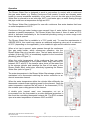
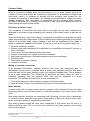
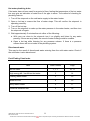
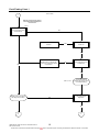
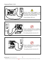
Rheem Australia Pty Ltd ABN 21 098 823 511 SERVICE INSTRUCTIONS Rheem Water Star TM039 Revision: A Published: January 09 W8100401 This document is stored and maintained electronically by Service. All printed copies not bearing this statement in RED are deemed “uncontrolled” Contents Introduction .......................................................................................................................... 3 Safety Warning .................................................................................................................... 3 Heater Model Identification Number .................................................................................... 3 Specifications....................................................................................................................... 4 Preventative Maintenance ................................................................................................... 4 Operation ............................................................................................................................. 5 Components and their Function ........................................................................................... 6 Wiring Diagram .................................................................................................................... 6 Common Faults ................................................................................................................... 7 Fault Finding Chart Index..................................................................................................... 8 General Fault Finding Chart ................................................................................................. 9 Fault Finding Chart 1 ......................................................................................................... 10 Fault Finding Chart 1.1 ...................................................................................................... 11 Fault Finding Chart 2 ......................................................................................................... 14 Fault Finding Chart 3 ......................................................................................................... 15 Fault Finding Chart 4 ......................................................................................................... 16 Fault Finding Chart 5 ......................................................................................................... 17 Fault Finding Chart 6 ......................................................................................................... 18 Electrical Insulation Testing ............................................................................................... 18 Component Replacement Procedures ............................................................................... 19 Exploded View ................................................................................................................... 24 Replacement Parts List ...................................................................................................... 24 Rheem Electric Water Heater Warranty - (Australia Only) ................................................. 25 Document Revision History................................................................................................ 26 TM039 Rheem Water Star Service Instructions REV: A Date of Issue: 02/09 This document is stored and maintained electronically by 2 Service. All printed copies not bearing this statement in RED are deemed “uncontrolled” Introduction The information provided in these instructions is based on the water heater being installed in accordance with the Installation Instructions provided with each water heater Should you require further technical advice on a Rheem Water Star, contact your nearest Rheem Australia Service Department where all genuine replacement parts are also available. Safety Warning The purpose of this Service Manual is to provide sufficient information to allow a person with the skills as required by the controlling Regulatory Authorities to carry out effective repairs to a Rheem Water Star in the minimum of time. Safety precautions or areas where extra care should be observed when conducting tests outlined in this service manual are indicated by print in bold italics and/or a warning symbol. Take care to observe the recommended procedure. “Live” testing to be conducted. Personal Protective Clothing (PPE) shall be worn and an RCD shall be installed between the power point and 3-pin cord of the water heater to reduce the risk of electric shock. Isolate power before conducting the indicated test Hot surface or liquid. Personal Protective Clothing (PPE) shall be worn to reduce the risk of scalding. General warning symbol. Observe the instructions accompanying the symbol. If the supply cord is damaged, it must be replaced by the manufacturer or its service agent or a similarly qualified person in order to avoid a hazard. When handling pipe work attached to the Rheem Water Star, assume that all pipes are carrying hot water. Personal Protective Equipment should be worn to prevent scalds or burns. Heater Model Identification Number The identification number is designed to convey detailed information about the water heater to which it is attached. The model number consists of 8 digits. W 8 1 004 0 1 W – Water Star 8 - 70°C temperature limited 1 – Single Heating Unit Rated Capacity in Litres 0 – Not fitted Top Element Rating 1 – 800 Watts Bottom Element Rating Note: Model number, serial number and date of manufacture should be quoted in all correspondence. TM039 Rheem Water Star Service Instructions REV: A Date of Issue: 02/09 This document is stored and maintained electronically by 3 Service. All printed copies not bearing this statement in RED are deemed “uncontrolled” Specifications 800 70 Inlet Outlet T&PR RP¾/20 RP½/15 Element Rating (w) 680 Water Connections T/stat Type T & PR Valve Rating (kPa) 1000 T/stat setting (ºC) Rated Capacity (Litres) 4 Without ECV Capacity 004 Maximum Inlet Pressure (kPa) With ECV Series W81 Model Fixed 800 Preventative Maintenance It is suggested for peak performance that the water heater be serviced annually. 1. Check for discharge from the T&PR valve. When the element is operating a small discharge of water may be evident. Direct access to the valve is via the circular plastic cover at the top of the unit. Operate the valve-easing lever to ensure the valve opens and resets properly. Always open and close the valve gently. The T&PR valve should be replaced at 5-yearly intervals. 2. Check for leaks at all tank fittings. 3. Check for signs of excessive corrosion on the water heater jacket. 4. Isolate power to the water heater and check all electrical connections for signs of overheating due to poor connection. 5. Conduct an insulation test on the water heater. (Refer to page 18) TM039 Rheem Water Star Service Instructions REV: A Date of Issue: 02/09 This document is stored and maintained electronically by 4 Service. All printed copies not bearing this statement in RED are deemed “uncontrolled” Operation The Rheem Water Star is designed to work in conjunction (in series) with a continuous flow gas water heater, e.g. Rheem Continuous Flow models. It works as a booster water heater to ensure immediate availability of hot water. As such the inlet pipe to the Rheem Water Star is referred to as an inlet pipe, NOT a cold water pipe, as water flowing through this pipe could have a temperature as high as 60ºC. The Rheem Water Star is designed for use with continuous flow water heaters that have an outlet temperature of 60°C. Continuous flow gas water heaters pass several litres of water before the temperature reaches a useable temperature. The Rheem Water Star stores 4 litres of water at 70°C which is delivered immediately to the household plumbing saving on water usage each time a hot tap is opened. The Rheem Water Star is available in a 70ºC model only. To meet the requirements of AS/NZS 3500.4, this model may require an additional tempering valve set at a maximum of 50°C (depending on the application), to be installed in pipe work to ablution areas. When a hot tap is opened, water passes through the continuous flow gas water heater, which commences operation, into the Rheem Water Star via a transfer valve. The hot water stored in the cylinder (4 litres @ 70ºC) is immediately supplied to the household plumbing (refer to Figure 1). When the outlet temperature of the continuous flow gas water heater (inlet temperature to the Rheem Water Star) has risen to between 52°C and 56°C the transfer valve shuts off the water flow to the storage cylinder and transfers the flow of hot water to the Rheem Water Star‟s outlet pipe, effectively bypassing the Rheem Water Star (refer to figure 2). The water temperature in the Rheem Water Star storage cylinder is maintained via a thermostat switching the active conductor to an electric immersion element. Figure 1 When the water temperature within the cylinder falls sufficiently the thermostat contacts close supplying power to the element. Once the water temperature reaches the set point of the thermostat (70°C), the contacts open cutting power to the element. A double pole „manual reset‟ over temperature cut out is incorporated into the thermostat to provide additional protection in the event the controlling thermostat contacts fail. The ECO contacts open at a water temperature of between 80ºC and 88ºC Figure 2 Figure 2 TM039 Rheem Water Star Service Instructions REV: A Date of Issue: 02/09 This document is stored and maintained electronically by 5 Service. All printed copies not bearing this statement in RED are deemed “uncontrolled” Components and their Function Temperature and Pressure Relief Valve: A T&PR valve is designed to provide automatic relief to the water heater by discharging water in case of excessive temperature, pressure or both. Never fit a T&PR Valve with a pressure rating greater than that indicated on the product-rating label. Over Temperature Energy Cut Out (E.C.O.): An ECO is a temperature-sensing device in combination with the thermostat that automatically cuts off the supply of electrical energy to prevent excessive water temperature occurring. This device will not reset automatically but may be manually reset once temperatures have fallen to a safe level. Thermostat: A thermostat is a device, responsive to temperature, which controls the supply of electrical energy to the element to maintain the stored water at the required temperature. Heating Unit (Element): An element is a tubular device containing an electric resistance that converts electrical energy into heat. The maximum rating of the Rheem Water Star is 800 watts. Transfer Valve: A 3 way valve, sensitive to temperature that simultaneously opens one outlet and closes the other transferring the direction of water flow. Wiring Diagram TM039 Rheem Water Star Service Instructions REV: A Date of Issue: 02/09 This document is stored and maintained electronically by 6 Service. All printed copies not bearing this statement in RED are deemed “uncontrolled” Common Faults When a complaint is lodged about the performance of a hot water system there are a number of causes that should be checked and eliminated. In an attempt to pinpoint the most likely cause it is important to discuss with the customer their reasons for the complaint, the duration of the problem, any change in circumstances or usage and recent weather conditions. This information in conjunction with the following listed common complaints will assist you in locating the most likely cause. All procedures assume there is water flowing through the water heater. Excessive hot water usage The complaints of insufficient hot water and no hot water can on many occasions be attributed to hot water usage exceeding the capacity of the water heater to provide hot water. When first attending a call of this nature it is essential to establish the probable hot water usage by querying the usage habits of the household and comparing this with the potential delivery of the model water heater installed. It can then be established if the usage is within or outside the capacity of the model. The areas to look at for excessive usage are: 1. Automatic washing machines. 2. Shower output rate exceeding 12 litres/minute for mixed water and being 5 minutes or more, in duration. 3. Two or more showers operating at the same time. 4. Change of occupancy or number of persons increased. 5. High water pressure area. (Excessive pressure relief valve discharge). 6. Plumbing leaks. 7. Thermostat temperature setting. 8. Crossed connection. Mixing or crossed connections If an automatic dishwasher, washing machine, flick mixer tap, tempering valve or thermostatic mixing valve is installed there is always the possibility that the cold water could mix with the hot water through a faulty or incorrectly installed valve. This is referred to as a cross connection. The complaints of insufficient hot water, water too cold or excessive discharge from the pressure relief valve may be attributed to a cross connection. The method of checking for a cross connection is: 1. Turn off the stopcock on the cold water supply to the water heater. 2. Open a hot tap. If water flow is persistent and cold a cross connection exists. Water hammer A water heater will not cause water hammer, however valves associated with the water heater may be the source of the problem i.e. cold-water stopcock, non-return valve or relief valve. Most water hammer problems are associated with plumbing, hot and cold or appliances i.e. solenoid valves, ballcocks, loose pipes, sharp angles in pipe work, faulty or worn valve parts, loose tap washers or neighbouring equipment. High water pressure areas will have more complaints of this nature and the use of a pressure-limiting valve (PLV) to reduce the household cold-water pressure will usually solve most problems. TM039 Rheem Water Star Service Instructions REV: A Date of Issue: 02/09 This document is stored and maintained electronically by 7 Service. All printed copies not bearing this statement in RED are deemed “uncontrolled” Hot water plumbing leaks If hot water has not been used for a period of time, feeling the temperature of the hot water line may give an indication of water flow if the pipe is warm. The method of checking for plumbing leaks is: 1. Turn off the stopcock on the cold water supply to the water heater. 2. Open a hot tap to ensure the flow of water stops. This will confirm the stopcock is operating correctly. 3. Turn off the hot tap. 4. Turn on the stopcock to make up the water pressure in the water heater, and then turn the stopcock off again. 5. Wait approximately 5 minutes then do either of the following: a. With your ear close to the stopcock turn it on slightly and listen for any water passing. If there are any leaks, the sound of water flowing would be audible. b. Open a hot tap while listening for any pressure release. If there is a pressure release there will be no leaks in the plumbing system. Discoloured water This may be the result of discoloured water entering from the cold water mains. Check if the cold water is also discoloured. Fault Finding Chart Index Fault Chart number Page 1, 1.1 10, 11 High energy bill / Insufficient hot water 2 14 Leaking water heater 3 15 Water too hot 4 16 Noisy water heater 5 17 Electrical insulation test 6 18 No hot water TM039 Rheem Water Star Service Instructions REV: A Date of Issue: 02/09 This document is stored and maintained electronically by 8 Service. All printed copies not bearing this statement in RED are deemed “uncontrolled” General Fault Finding Chart Fault Diagnosis Is the complaint for no hot water ? YES 1. NO Is the complaint for a high energy bill or insufficient hot water? YES 2. NO Is the complaint for a leaking water heater? YES 3. NO Is the complaint for water too hot? YES 5. Noisy Water Heater TM039 Rheem Water Star Service Instructions REV: A Date of Issue: 02/09 This document is stored and maintained electronically by 4. 9 Service. All printed copies not bearing this statement in RED are deemed “uncontrolled” Fault Finding Chart 1 No hot water 1. Warning: Terminals may be live. Personal Protective Equipment must be worn. Test 1 Is 240 volts present at the terminal block? NO Restore power and advise customer YES Is the isolating switch turned off? NO YES Possible fault in household electrical wiring. Continue with diagnosis to confirm water heater is operational. NO Is the fuse blown at the switchboard? YES Tests 2, 3 & 4 Isolate power and continue with diagnosis procedure NO Conduct an electrical insulation test (refer to section on insulation testing) Is the reading below 1 Megaohm? YES 1.1 TM039 Rheem Water Star Service Instructions REV: A Date of Issue: 02/09 This document is stored and maintained electronically by 6 10 Service. All printed copies not bearing this statement in RED are deemed “uncontrolled” Fault Finding Chart 1.1 No hot water 1.1 Test 5 Are the thermostat ECO contacts closed? NO Replace thermostat YES Test 6 Are the thermostat contacts closed? NO Is the water in the tank at least 6 degrees lower than the thermostat setting? YES Replace thermostat NO Replace thermostat NO Slide the thermostat out from under the retaining clamp and allow base to cool. YES Test 6 YES Did the thermostat contacts close? Test 7 Does the element have the correct resistance? NO Replace element NO Locate wiring failure and repair YES Test 8 Is the overall resistance of the water heater correct? YES TM039 Rheem Water Star Service Instructions REV: A Date of Issue: 02/09 This document is stored and maintained electronically by Water heater electrically OK. 2. 11 Service. All printed copies not bearing this statement in RED are deemed “uncontrolled” Component Tests 1, 5, & 6 Test 1 With the water heater plugged in and switched on, use a multimeter on the AC volts scale and measure between active and neutral on the terminal block. Normal voltage is 240 volts Test 5 Using a multimeter on the x1 resistance scale, measure between terminals 3 and 4 on the thermostat. The reading should be less than 1Ω. Test 6 Using a multimeter on the x1 resistance scale, measure between terminals 1 and 2 on the thermostat. The reading should be less than 1Ω. TM039 Rheem Water Star Service Instructions REV: A Date of Issue: 02/09 This document is stored and maintained electronically by 12 Service. All printed copies not bearing this statement in RED are deemed “uncontrolled” Component Tests 7 & 8 Test 7 Using a multimeter on the x1 resistance scale, measure the resistance of the element across the wires that connect to terminals 2 and 4 of the thermostat. Normal resistance for the element is 6879 ohms. Test 8 Using a multimeter on the x1 resistance scale, measure between active and neutral on the terminal block. Normal resistance when the thermostat contacts are closed is 68 - 79 ohms TM039 Rheem Water Star Service Instructions REV: A Date of Issue: 02/09 This document is stored and maintained electronically by 13 Service. All printed copies not bearing this statement in RED are deemed “uncontrolled” Fault Finding Chart 2 High energy bill/ Insufficient hot water 2 Refer to Rheem sizing guide Has the usage pattern changed recently, ie.additional appliances or people using hot water? Is the heater of sufficient size for the customer‟s ongoing needs? YES NO Recommend a hot water usage pattern that will suit the water heater and the customer‟s needs. YES NO Is the T&PR valve continuously discharging water? YES Is the water supply pressure more than 80% of the T&PR valve rating? Recommend a water heater of sufficient capacity to meet the customer‟s needs. YES Fit pressure limiting valve (PLV), if not already installed. Replace faulty PLV. Replace faulty T&PR valve. NO Replace T&PR valve with one with the correct pressure rating. Do not use reconditioned T&PR valves. NO Is the correct T&PR valve fitted? NO Check for cross water connection. Replace the T&PR valve (if required.). YES Are there any plumbing leaks, crossed connections or dripping taps? NO Repair any leaks. Isolate cross connections. YES Measure the water temperature at the T&PR valve drain by gently lifting the easing lever Does the cylinder water temperature correspond with the thermostat setting? NO Has there been a recent large draw off of hot water YES NO YES Is the transfer valve allowing water to pass in both directions? Replace the thermostat Allow heater time to recover YES Replace the transfer valve NO Water Star OK. Possible fault with continuous flow gas water heater. (Refer to relevant service instructions). NO Is a tempering valve installed? AS/NZS 3500 Part 4 only requires fixtures used for ablution purposes to be tempered. If practical a 2-zone plumbing solution may be offered. Possible fault with tempering valve YES TM039 Rheem Water Star Service Instructions REV: A Date of Issue: 02/09 This document is stored and maintained electronically by 14 Service. All printed copies not bearing this statement in RED are deemed “uncontrolled” 2 Zone Plumbing Option Fault Finding Chart 3 Leaking Water Heater 3. Is the leak from or near the top? YES NO Is the leak from the element barrel weld? YES Replace the cylinder YES NO Is the leak from the element gasket? NO YES Remove element and replace gasket Is the leak from the outlet pipe? NO Is the leak from the inlet tee weld? NO YES Replace the cylinder NO Is the leak from the drain pipe? Is the leak from the T&PR valve fitting weld? YES Is the leak from the T&PR valve? YES YES TM039 Rheem Water Star Service Instructions REV: A Date of Issue: 02/09 This document is stored and maintained electronically by Remove pipe and replace contite olives Remove the T&PR valve and reseal with thread tape 15 Service. All printed copies not bearing this statement in RED are deemed “uncontrolled” Fault Finding Chart 4 Water too hot 4 Is the outlet water temperature approx. 70 degrees? Water heater operating normally YES An external tempering valve should be considered if concerns surround children or elderly occupants NO Is the water temperature in the cylinder > 80 °C? Is the thermostat in good contact with the cylinder? YES Water temperature can be measured at the T&PR valve drain by gently lifting the easing lever YES NO Remove the thermostat, retension the bracket and refit the thermostat Allow the water heater to recover and re-check the water temperature Replace the thermostat NO Is the water temperature in the cylinder < 80 °C? YES NO Fault rectified The continuous flow gas water heater connected to a Rheem Water Star MUST have a maximum outlet temperature of 60 degrees Has the correct continuous flow gas water heater been installed? NO Possible fault with continuous flow gas water heater. Refer to service instructions on relevant model for fault finding YES TM039 Rheem Water Star Service Instructions REV: A Date of Issue: 02/09 This document is stored and maintained electronically by Reset the outlet temperature of the continuous flow water heater or replace with a suitable model 16 Service. All printed copies not bearing this statement in RED are deemed “uncontrolled” Fault Finding Chart 5 Noisy Water Heater 5. Is the noise only evident during the heating cycle? YES Check for: (A) Mineral build-up on the element. (B) Mineral or sludge build-up inm the cylinder (C) Normal noises associated with heating water. YES Refer to water hammer causes, under Common Faults NO Check all other appliances that can generate noise, eg. washing machine, dishwasher, etc. YES Cylinder contracting due to pressure release when hot tap is opened. This can be accompanied by a creaking or cracking sound from the insulation. This noise is normal operation. NO Check for faulty stop cock, non-return valve or T&PR valve. NO Is the noise water hammer? NO Is the noise only evident when water is flowing through the water heater? YES Is the noise a metallic popping sound? NO Is the water pressure more than 80% of the T&PR valve rating? Check for restrictionsin pipe work, faulty valves, loose plumbing or other appliances, eg. Washing machine or dishwasher. Fit a 600kPa PLV if pressure is excessive. YES TM039 Rheem Water Star Service Instructions REV: A Date of Issue: 02/09 This document is stored and maintained electronically by 17 Service. All printed copies not bearing this statement in RED are deemed “uncontrolled” Fault Finding Chart 6 6 Electrical Insulation Test Disconnect the wires to the element from the thermostat and megger between each element wire and earth. Is the reading below 1 Megaohm? YES Rewire fuse or reset circuit breaker, if necessary NO Disconnect the remaining wires from the thermostat and megger between each thermostat terminal and earth. Replace element Is the reading below 1 Megaohm? YES Replace thermostat Rewire fuse or reset circuit breaker, if necessary NOTE: Unplug continuous flow water heater prior to commencing insulation testing NO Check for: Faulty 3 pin outlet socket Pinched or damaged wiring touching the heater chassis Electrical Insulation Testing There are three basic test procedures that should be carried out when the operation and function of a water heater‟s electrical system is in doubt. Test 2 - To check insulation resistance of the water heater Neutral Circuit (reading not to be below 1 MΩ). 1. Switch off power at GPO and unplug power cord from GPO (unplug continuous flow water heater). 2. Connect megger leads to the neutral of the water heater wiring and earth. 3. Operate megger. A reading above 1 MΩ should be obtained. 4. If a reading below 1 MΩ is indicated, all component parts will need to be individually tested to locate the fault. Refer to flow diagram chart 6, above. Test 3 - To check insulation resistance of the water heater Active Circuit (reading not to be below 1 MΩ). 1. Connect megger leads to the active of the water heater wiring and earth. 2. Operate megger. A reading above 1 MΩ should be obtained. 3. If a reading below 1 MΩ is indicated, all component parts will need to be individually tested to locate the fault. Refer to flow diagram chart 6, above. Test 4 - To check “Continuity” of water heater electrical circuit. 1. Set megger to resistance scale or multimeter to x1 resistance scale. 2. Measure between the active and the neutral of the water heater. If a reading between 68-79 ohms is not indicated, all electrical component parts will need to be individually tested to locate the fault. 3. Reconnect the power cord. Note: If continuing with diagnostic procedure flow chart 1.1 do not reconnect the power cord. TM039 Rheem Water Star Service Instructions REV: A Date of Issue: 02/09 This document is stored and maintained electronically by 18 Service. All printed copies not bearing this statement in RED are deemed “uncontrolled” Component Replacement Procedures Draining the Water Heater (Procedure 1) 1. Switch off power at GPO, unplug power cord from GPO and isolate the water supply to the water heater 2. Relieve pressure from the water heater by easing the T&PR valve or through a hot tap. 3. Disconnect the inlet water supply pipe 4. Fit a drain hose to the inlet water connection and run the other end to a drain or safe location. 5. Open the temperature and pressure relief valve to allow air into the system. NOTE: A small amount of water will be left in the cylinder. Transfer Valve (Procedure 2) 1. 2. 3. 4. 5. Drain the water heater (refer to procedure 1 above) Remove the outer jacket screws. Remove the outer jacket and front polystyrene insulation to expose the water heater. Disconnect the inlet pipe from the transfer valve by undoing the ¾” brass nut. Disconnect the outlet pipe from the transfer valve by undoing the ¾” brass nut. Remove the old transfer valve. 6. Fit the replacement transfer valve and assemble in reverse order. 7. Restore the water supply and check for leaks. 8. Purge air from the system through hot taps. 9. Refit the front polystyrene insulation and outer jacket. 10. Restore the power supply to the water heater. Temperature and Pressure Relief Valve (Procedure 3) Never fit a T&PR valve with a rating higher than that indicated on the water heater rating plate. Do not use reconditioned T&PR valves. 1. Partially drain the water heater (refer to procedure 1 on page 19). 2. Remove the outer jacket screws. 3. Remove the outer jacket and front polystyrene insulation to expose the water heater. 4. Disconnect the outlet pipe from the T&PR valve by undoing the ¾” brass nut. 5. Disconnect the drain line fitting from the T&PR valve 6. Unscrew the T&PR valve from the top of the cylinder. 7. Confirm the replacement T&PR valve is the correct rating and refit using thread tape. 8. Reassemble in the reverse order of above 9. Restore the water supply. 10. Check the T&PR valve thread and connections for leaks. 11. Operate the T&PR valve lever to reset relief drain. TM039 Rheem Water Star Service Instructions REV: A Date of Issue: 02/09 This document is stored and maintained electronically by 19 Service. All printed copies not bearing this statement in RED are deemed “uncontrolled” 12. Purge air from the system through hot taps. 13. Refit the front polystyrene insulation and outer jacket. 14. Restore the power supply to the water heater. Thermostat (Procedure 4) 1. 2. 3. 4. 5. 6. 7. Switch off power at GPO and unplug power cord from GPO. Remove the outer jacket screws. Remove the outer jacket and front polystyrene insulation to expose the water heater. Confirm the wiring is as per the wiring diagram on page 6. Disconnect the wiring to the thermostat. Slide the thermostat out from under the retaining clamp. Slide the replacement thermostat under the clamp ensuring the thermostat is held firmly against the cylinder. 8. Reconnect the wiring as per the wiring diagram on page 6. 9. Check water heater internal wiring insulation for cracking. 10.Refit the front polystyrene insulation and outer jacket. 11.Conduct an electrical insulation test. Refer to page 18. 12.Restore power to the water heater. Inlet Water Connector (Procedure 5) 1. 2. 3. 4. 5. 6. 7. Drain the water heater (refer to procedure 1 on page 19). Remove the outer jacket screws. Remove the outer jacket and front polystyrene insulation to expose the water heater. Undo the brass nuts retaining the inlet pipe to the inlet fitting and the transfer valve. Loosen the remaining two brass nuts retaining the transfer valve. Remove the two (2) screws retaining the inlet fitting to the bottom chassis. Rotate the bottom of the transfer valve towards the front of the water heater so the inlet water pipe could be manoeuvred free. 8. Fit the replacement inlet connector into place. 9. Reassemble in reverse order of above. 10.Restore the water supply. 11.Purge air from the system through hot taps and check for leaks. 12.Refit front polystyrene insulation and outer jacket. 13.Restore the power supply to the water heater. TM039 Rheem Water Star Service Instructions REV: A Date of Issue: 02/09 This document is stored and maintained electronically by 20 Service. All printed copies not bearing this statement in RED are deemed “uncontrolled” Outlet Water Connector (Procedure 6) 1. 2. 3. 4. Drain the water heater (refer to procedure 1 on page 19). Remove the outer jacket screws. Remove the outer jacket and front polystyrene insulation to expose the water heater. Disconnect the outlet water pipe from the T&PR valve, transfer valve and outlet water connector by undoing the ¾” brass nuts. 5. Remove the outlet pipe. 6. Remove the two (2) screws retaining the outlet water connector fitting to the bottom chassis. 7. Fit the replacement outlet water connector 8. Reassemble in reverse order. 9. Restore the water supply. 10.Purge air from the system through hot taps and check for leaks. 11.Refit front polystyrene insulation and outer jacket. 12. Restore the power supply to the water heater. T&PR Valve Drain Connector (Procedure 6) 1. 2. 3. 4. Drain the water heater (refer to procedure 1 on page 19). Remove the outer jacket screws. Remove the outer jacket and front polystyrene insulation to expose the water heater. Disconnect the T&PR drain pipe from the T&PR valve and drain connector by undoing the brass nuts. 5. Remove the drain pipe. 6. Remove the two (2) screws retaining the connector to the water heater chassis. 7. Fit the replacement drain connector 8. Reassemble in reverse order of above. 9. Restore the water supply. 10.Purge air from the system through hot taps and check for leaks. 11.Refit front polystyrene insulation and outer jacket. 12.Restore the power supply to the water heater. TM039 Rheem Water Star Service Instructions REV: A Date of Issue: 02/09 This document is stored and maintained electronically by 21 Service. All printed copies not bearing this statement in RED are deemed “uncontrolled” Element (Procedure 9) 1. 2. 3. 4. 5. 6. 7. 8. 9. Drain the water heater (refer to procedure 1 on page 19). Remove the outer jacket screws. Remove the outer jacket and front polystyrene insulation to expose the water heater. Slide the thermostat out of the retaining clamp Disconnect the T&PR valve drain line and outlet water pipe from the T&PR valve. Disconnect the transfer valve from the cylinder by undoing the ¾” brass nut. Remove the cylinder from the water heater and invert it. Unscrew the element using a 42mm spanner or tube socket. Withdraw the element. Care must be taken to ensure the loop of the element does not catch in the cylinder opening and open out inside the cylinder. NOTE: Do not “cut off” the element and leave a portion inside the cylinder 10.Clean around the cylinder fitting. Ensure that the replacement element is of the correct rating and carefully insert and screw into the cylinder. 11.Reassemble in reverse order of above. 12.Restore the water supply. 13.Purge air from the system through hot taps and check for leaks. 14.Refit front polystyrene insulation and outer jacket. 15.Conduct an electrical insulation test (refer to page 18). 16.Restore the power supply to the water heater. Cylinder Replacement (Procedure 10) 1. 2. 3. 4. Drain the water heater (refer to Procedure 1 on page 19). Remove the T&PR valve (follow steps 2-6 of Procedure 3 on page 19). Remove the element (follow steps 2-9 of Procedure 9 on page 22). Refit the element & T&PR valve to the replacement cylinder. NOTE: Depending on the age of the water heater consideration should be given to fitting a new T&PR valve. 5. Fit the replacement cylinder into the rear polystyrene housing. Note: The cylinder will need to be supported until the T&PR valve drain line and outlet pipe are connected. 6. Reassemble in reverse order of above. 7. Restore the water supply. 8. Operate the T&PR valve lever to reset relief drain. 9. Purge air from the system through hot taps and check the entire water heater for leaks. 10.Refit front polystyrene insulation and outer jacket. 11.Conduct an electrical insulation test. (Refer to page 18). 12.Restore the power supply to the water heater. TM039 Rheem Water Star Service Instructions REV: A Date of Issue: 02/09 This document is stored and maintained electronically by 22 Service. All printed copies not bearing this statement in RED are deemed “uncontrolled” 3 Pin Outlet Socket 1. Switch off power at GPO and unplug power cord from GPO. 2. Unplug the continuous flow water heater 3 pin plug from the socket. 3. Remove the outer jacket screws. 4. Remove the outer jacket and front polystyrene insulation to expose the water heater. 5. Confirm the wiring is as per the wiring diagram on page 6. 6. Disconnect the wiring from the active, neutral and earth connectors. 7. Remove the screw from the centre of the 3 pin socket outlet and remove the bottom half of the 3 pin outlet socket. 8. Remove the upper half of the 3 pin outlet socket from the water heater. 9. Reassemble in reverse order of above. NOTE: When fitting the replacement 3 pin outlet socket ensure the bottom half is orientated correctly so the earth pin entry aligns with the earth socket in the top half of the plug. 10.Refit front polystyrene insulation and outer jacket. 11.Conduct an electrical insulation test. (Refer to page 18). 12.Restore the power supply to the water heater. TM039 Rheem Water Star Service Instructions REV: A Date of Issue: 02/09 This document is stored and maintained electronically by 23 Service. All printed copies not bearing this statement in RED are deemed “uncontrolled” Exploded View Replacement Parts List Item 1 2 3 4 5 6 7 8 9 10 11 12 13 14 15 Description Base – cabinet Insulation - rear T&PR valve Valve connection kit T&PR valve drain pipe ½” Nut – M4 Wiring ass earth (GPO socket) Wiring loom & cord set Wiring loom – thermostat Washer – flat Nut – ½” contite Washer – tooth lock Cone fitting ½” T&PR valve drain fitting Inlet/Outlet fitting TM039 Rheem Water Star Service Instructions REV: A Date of Issue: 02/09 This document is stored and maintained electronically by Part Nº 140003 090160 220350 220371 220366 080406 080402 080403 080400 080405 220359 080404 220360 220362 220361 Item 16 17 18 19 20 21 22 23 24 25 26 27 28 29 Description Name band-Rheem Water Star Front cover – cabinet Cover – T&PR valve Insulation - front Pipe – Outlet ¾” Transfer valve Pipe – Inlet ¾” Nut – ¾” contite Cone fitting ¾” Cylinder assembly unit Thermostat R/S – ST1203133 Clamp – thermostat assy. Heating unit – 800 watt GPO socket Part Nº 125996 140001 221720-1 090159 220373 220370 220372 220357 220358 050032 052075 102501 050022 080410 24 Service. All printed copies not bearing this statement in RED are deemed “uncontrolled” Rheem Electric Water Heater Warranty - (Australia Only) WARRANTY CONDITIONS 1. 2. 3. 4. This warranty is applicable only to water heaters st manufactured from 1 June 2008. The water heater must be installed in accordance with 5. the Rheem water heater installation instructions, supplied with the water heater, and in accordance with all relevant statutory and local requirements of the State in which the water heater is to be installed. Where a failed component or water heater is replaced 6. under warranty, the balance of the original warranty period will remain effective. The replaced part or water heater does not carry a new warranty. Where the water heater is installed outside the boundaries of a metropolitan area as defined by Rheem or further than 25 km from a regional Rheem branch office, or an Accredited Service Agent, the 7. cost of transport, insurance and travelling costs between the nearest Rheem Accredited Service Agent‟s premises and the installed site shall be the owner‟s responsibility. Where the water heater is installed in a position that does not allow safe, ready access, the cost of accessing the site safely, including the cost of additional materials handling and / or safety equipment, shall be the owner‟s responsibility. The warranty only applies to the water heater and original or genuine (company) component replacement parts and therefore does not cover any plumbing or electrical parts supplied by the installer and not an integral part of the water heater, e.g. pressure limiting valve; isolation valves; non-return valves; electrical switches; pumps or fuse. The water heater must be sized to supply the hot water demand in accordance with the guidelines in Rheem water heater literature. WARRANTY EXCLUSIONS A). REPAIR AND REPLACEMENT WORK WILL BE CARRIED OUT AS SET OUT IN THE RHEEM WATER HEATER WARRANTY , HOWEVER THE FOLLOWING EXCLUSIONS MAY CAUSE THE WATER HEATER WARRANTY TO BECOME VOID AND MAY INCUR A SERVICE CHARGE AND / OR COST OF PARTS. 1. 2. 3. Accidental damage to the water heater or any component, including: Acts of God; failure due to misuse; incorrect installation; attempts to repair the water heater other than by a Rheem Accredited Service Agent or the Rheem Service Department. Where it is found there is nothing wrong with the water heater; where the complaint is related to excessive discharge from the temperature and / or pressure relief valve due to high water pressure; where there is no flow of hot water due to faulty plumbing; where water leaks are related to plumbing and not the water heater or water heater components; where there is a failure of gas, electricity or water supplies; where the supply of gas, electricity or water does not comply with relevant codes or acts. Where the water heater or water heater component has failed directly or indirectly as a result of: excessive water pressure, excessive temperature and / or thermal input; blocked overflow / vent drain; corrosive atmosphere; ice formation in the pipe work to or from the water heater. 4. Where the water heater is located in a position that does not comply with the Rheem water heater installation instructions or relevant statutory requirements, causing the need for major dismantling or removal of cupboards, doors or walls, or use of special equipment to bring the water heater to floor or ground level or to a serviceable position. 5. Repair and / or replacement to the water heater due to scale formation in the waterways or the effects of either corrosive water or water with a high chloride or low pH level when the water heater has been connected to a scaling or corrosive water supply or a water supply with a high chloride or low pH level as outlined in the Owner‟s Guide and Installation Instructions booklet. B) SUBJECT TO ANY STATUTORY PROVISIONS TO THE CONTRARY, THIS WARRANTY EXCLUDES ANY AND ALL CLAIMS FOR DAMAGE TO FURNITURE, WALLS, FOUNDATIONS OR ANY OTHER CONSEQUENTIAL LOSS EITHER DIRECTLY OR INDIRECTLY DUE TO LEAKAGE FROM THE WATER HEATER OR DUE TO LEAKAGE FROM FITTINGS AND / OR PIPE WORK OF METAL, PLASTIC OR OTHER MATERIALS CAUSED BY WATER TEMPERATURE, WORKMANSHIP OR OTHER MODES OF FAILURE. In addition to this warranty, the Trade Practices Act 1974 and similar laws in each state and territory provide the owner under certain circumstances with certain minimum statutory rights in relation to your Rheem water heater. This warranty must be read subject to that legislation and nothing in this warranty has the effect of excluding or restricting those rights. RHEEM WATER HEATERS AUSTRALIA FOR SERVICE TELEPHONE 131 031 AUSTRALIA RHEEM AUSTRALIA PTY. LTD. A.B.N 21 098 823 511 or refer local Yellow Pages NOTE: Every care has been taken to ensure accuracy in preparation of this publication. No liability can be accepted for any consequences, which may arise as a result of its application. TM039 Rheem Water Star Service Instructions REV: A Date of Issue: 02/09 This document is stored and maintained electronically by 25 Service. All printed copies not bearing this statement in RED are deemed “uncontrolled” Document Revision History Title: Service Instructions - Rheem Water Star Revision A Details of change Service Instructions issued for Rheem Water Star TM039 Rheem Water Star Service Instructions REV: A Date of Issue: 02/09 This document is stored and maintained electronically by Document Nº: TM039 D.O.I. 2/09 26 Service. All printed copies not bearing this statement in RED are deemed “uncontrolled”