1
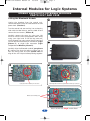
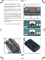
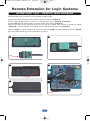
Bluetooth Modules Manual v4
29/6/09
10:54 am
Page 1
INSTRUCTION
MANUAL
2009 Bluetooth Modules
Logic Systems Internal Modules
2217
Single stereo Bluetooth internal module, for use with Kits L-1 and L-IW
2218
Twin stereo Bluetooth internal module, for use with Kit L-1
2221
Optional remote cable and housing, for use with Part 2217 or 2218 when a Logic is
bike powered.
Super Pro Systems Remote Modules
2223
Single stereo Bluetooth remote module, for use with Kits SP-A and SP-ARC
2224
Twin stereo Bluetooth remote module, for use with Kits SP-A and SP-ARC
It is very important that you fully read and understand all of
these instructions before installation and use.
These parts are designed for domestic motorcycle use.
Bluetooth Modules Manual v4
29/6/09
10:55 am
Page 2
Internal Modules for Logic Systems
STEREO BLUETOOTH INTERNAL MODULES
PARTS 2217 AND 2218
Fitting the Bluetooth Module
A
Unplug the headsets from the control unit,
remove the battery cover and the batteries or bike
power lead. (Picture A).
Turn the control hub over and lay it on a clean dry
cloth with the label side up, peel the label off and
remove the two screws. (Picture B).
Carefully remove the cover by using your left
hand to hold the front panel/cables down while
using your right hand to lift the top cover off,
which exposes the main printed circuit board and
you will see the two black 8-pin connectors (Logic
picture C), or single 8-pin connector (Logic
Independence Wireless picture D).
B
Carefully align the Bluetooth module (per picture
E) making sure that the radius cut-outs line up
with the fixing posts and take special care to
align all the 8 or 16 pins before pressing together.
C
D
Logic system with 2 black 8 pin connectors
Logic Independence Wireless system with 1 black 8 pin connector
E
Radius cuts and fixing posts
Picture shown with Single module fitted
2
Bluetooth Modules Manual v4
29/6/09
10:55 am
Setting the MODE selector switch
Page 3
F
Set the mode selector switch to Mode 2
(pictures F and G) to make the audio affect
other inputs as Aux 2 does.
Set the mode selector switch to Mode 3
(pictures F and H)to make the audio affect other
inputs as Aux 3 does, this is the standard factory
setting.
After setting the mode selector switch, fit the new
raised profile lid taking care to first align the front
panel into the side slots (as per picture I) and
make sure the new lid fits evenly and snug around
the front panel and back cover area. Check that
the printed circuit board (PCB) and battery tray
are sitting correctly, then fit the two new long
fixing screws.
Mode selector switch
AUT01
Picture shown with Twin module fitted
G
Replace the power lead or batteries and then
the battery cover.
TURN TO PAGE 7 FOR PAIRING INSTRUCTIONS.
Mode 2
H
Mode 3
I
Mode selector switch
AUT02
J
Side slots
3
Bluetooth Modules Manual v4
29/6/09
10:55 am
Page 4
Remote Extension for Logic Systems
USING PART 2221 - REMOTE LEAD HOUSING
Recommended to be used when you bike power a Logic system.
Position Part 2217 or 2218 into the remote housing as shown in picture K.
Set the mode selector switch to mode 2 or 3 (as shown on page 3, pictures F, G and H).
Connect end A of the remote lead to the main PCB in the housing (picture L).
Position the lead into the grommet and fit the lid and four screws, after making sure that the gasket
(picture M) is fitted correctly. The finished remote module should look as per picture N.
Open the Logic as in the instructions on page 2 and connect end B of the remote lead as shown in picture
O, fit the raised profile lid per the instructions on page 3.
K
L
End A
M
O
Gasket
N
End B
4
Bluetooth Modules Manual v4
29/6/09
10:55 am
Page 5
Remote Modules for Super Pro Systems
STEREO BLUETOOTH REMOTE MODULES
PARTS 2223 AND 2224
Fitting the Bluetooth Module
With the single module the 3.5mm jack plug is inserted in one of the 3.5mm Aux sockets found on the
front panel of the Super Pro system (picture 1).
With the twin module the 3.5mm jack plugs are inserted in two of the 3.5mm Aux sockets found on the
front panel of the Super Pro system (picture 1). Please refer to page 6 for Aux socket choice.
The power plug is inserted into the power socket found on the front panel of the Super Pro system.
The remote module comes supplied ready sealed.
TURN TO PAGE 7 FOR PAIRING INSTRUCTIONS.
1
2
2223
Power plug is inserted
in to Super Pro
Power Socket
4
AUT01
3.5mm jack plug is inserted in to Super Pro Aux Socket
Picture shown with Single module plugs
3
2224
Power plug is inserted
in to Super Pro Power Socket
Sealed remote module
AUT01
AUT02 with red band
Picture shown with Twin module plugs
5
Bluetooth Modules Manual v4
29/6/09
10:55 am
Page 6
CONNECTIVITY • LOGICAL MIXING AND CONTROL
Aux 2 • designed for Stereo GPS
Incoming audio on Aux 2 automatically reduces the stereo music level on Aux 4 to 50% to improve speech
clarity, while automatic gain control compensates for varying noise/speeds and the stereo audio can be
faded between the rider and passenger headsets (auto reduction and/or auto gain control can be switched
off for improved earplug use). You can use some phones via some GPS units, but in most cases you lose
the important GPS audio and safety camera warnings while using the phone through a GPS. This is why
we provide separate GPS and phone connectivity to manage this better for you.
Aux 3 • designed for Rider’s Stereo Phone
Incoming audio is amplified only to the rider’s headset, but can be switched for both rider and passenger
use. Incoming audio automatically cuts the stereo music on Aux 4 by 100% and reduces bike-to-bike audio
on Aux 1, plus stereo GPS audio on Aux 2 to 50% to improve phone conversation; while at the same time
it also disables the bike-to-bike VOX transmit mode to prevent your phone conversation been broadcast to
other bikes. *Some phones may require a hands free adaptor.
Aux 4 • designed for Stereo Music
Automatic gain control compensates for varying noise/speed conditions and the stereo audio can be faded
between the rider and passenger headsets. Rider and passenger speech plus audio from Aux 1 and 2
automatically reduce the stereo music on Aux 4 to 50%, while audio from Aux 3 fully cuts the music for
improved conversations (auto reduction and/or auto gain control can be switched off for improved earplug
use).
Aux 5 • designed for Passenger’s Stereo/Phone
Incoming audio is amplified only to the passenger’s headset, but can be switched to both rider and
passenger. Incoming audio has no effect to any other Aux connections so that the passenger can enjoy
their own stereo music without disruption to other inputs or outputs. We recommend using the optional
remote PTT if using a bike-to-bike radio, so that you can manually disable the VOX transmit mode when
the passenger is using their phone.
Optional, remote, Single or Twin Stereo Bluetooth Module/s
Connects into Aux 2, 3, 4 or 5.
Each of the stereo Bluetooth modules lets you connect wirelessly to one or two Bluetooth devices, so long
as one is using hands free profile (such as a mobile phone or GPS, etc) and the other uses advanced audio
profile (A2DP, such as stereo devices, mp3 players, etc). The twin Bluetooth module lets you connect to
between 1 and 4 Bluetooth devices.
6
Bluetooth Modules Manual v4
29/6/09
10:55 am
Page 7
GENERAL INSTALLATION OF REMOTE MODULES
Plan where you intend to route your lead between your module and Autocom system on the bike, ensuring
that the lead will reach between them. Avoid placing any parts near areas of high heat (engine, exhaust
etc), or near electrical noise (HT leads and coils, alternator and regulator etc) and where they may be
exposed to extreme damp (near to wheels or exposed areas under the fairing etc).
Prior to final installation, we recommend that you carefully position all parts, connected up, and try the
system to check for electrical interference with the engine running. If you hear any electrical noise you
should carefully move each part, one by one with the engine running and listening to the noise, to suitable
locations where any electrical noise is reduced to a minimum.
Secure all parts so that they will not interfere with steering, braking etc and not be trapped/crushed by
body panels or the seat or fall into chain/wheels etc.
Position the remote module as close or in line of sight to the device that it is to be paired with. It is not
recommended to position the module in positions where the signal has to pass through a person’s body, or
other solid objects that can weaken the signal.
PAIRING THE BLUETOOTH MODULES
Each Bluetooth module is capable of being connected to 2 Bluetooth devices at the same time; 1 using
A2DP profile and 1 using headset profile.
If you intend to connect 2 devices to each module it is important that you connect the A2DP device first.
If your mobile phone has A2DP profile and you pair this device first music from your phone will be played
via the Bluetooth module in stereo; during a phone call the module and your phone will automatically
change to Headset profile for the duration of the call. Doing this uses both available profiles and is counted
as 2 devices.
1.
Power up your Bluetooth module.
a)
Logic range battery powered. Connect riders headset.
b)
Logic range bike powered. Connect headset and turn on bike ignition.
c)
Super Pro range. Turn on bikes ignition.
2.
Following your Bluetooth devices instructions manual search for new Bluetooth device.
3.
When new device is found select AUTO1 (single module) or AUTO1 or AUT02 (twin module) and
enter pass code 0000.
4.
Repeat steps 2 and 3 if you need to connect further devices whilst leaving your system powered.
After a connection is made for the first time the connection should automatically pair each time the module
is powered and your device is in range; some devices will prompt you for permission to connect each time
this happens, this is a function of your device.
When used with a mobile phone the module will automatically answer a call when one is received; this is
a safety feature keeping the process hands free as not all mobile phones have auto answer.
7
Bluetooth Modules Manual v4
29/6/09
10:55 am
Page 8
MANUFACTURERS
12 MONTH
WARRANTY
If your
supplier has not given advice or
demonstrated how to set up or use our
products, please check with them before sending any
goods back for warranty.
All Autocom products are under warranty for a period of 12 months from the
date of original purchase, to the original purchaser, from an authorised Autocom
retailer. This warranty covers faulty materials or workmanship, subject to the goods
being used only as stated, and only for the purpose as described in the instruction
manuals. This does NOT apply to goods where they are used for any other purpose or in any
other way than is explained in the instructions. Nor where the goods have been subjected to
misuse, neglect or accidental damage, or used with any other vendor’s products, including
incorrect mechanical or electrical installation, or where the goods have been repaired, modified or
altered, without the manufacturer’s written authorisation.
The manufacturer's warranty is limited to the goods being returned pre paid to the manufacturer's factory,
with the original packaging and the original proof of purchase date. The goods must be intact for our
examination.
Where goods are accepted by the manufacturer, under the terms of the warranty
Where the manufacturer, under the terms of the warranty, accepts goods, they will be repaired free of
charge or replaced (at the option of the manufacturer). Where the goods are returned as faulty and are
found not to be, a charge will be payable to cover costs of inspection, testing, packing and return postage.
This warranty does not cover any consumable items such as batteries, replaceable hygiene foam coverings
for speakers and microphones, or any other items that are described within the instruction manuals as
being a consumable.
The manufacturer's warranty does not affect your statutory rights.
Autocom Products Limited
Unit 4, Tachbrook Link, Tachbrook Park Drive, Warwick CV34 6RH England.
Telephone:
Fax:
Email:
Website:
+44 (0)1926 431249
+44 (0)1926 431250
[email protected]
www.autocom.co.uk
We service what we make
For details of Autocom’s International distributors and support network, please see our
website. Please contact your supplier or Autocom for any further help or information.
UK Manufacturer and Distributor